Review

A Review of Challenges and Opportunities Associated with Bolted Flange Connections in the Offshore Wind Industry

by
Ali Mehmanparast
1,*,
Saeid Lotfian
2 and
Sukumara Pillai Vipin
3
1
Offshore Renewable Energy Engineering Centre, Cranfield University, Cranfield MK43 0AL, UK
2
Naval Architecture, Ocean and Marine Engineering Department, University of Strathclyde, Glasgow G1 1XQ, UK
3
Asset Integrity Management Section, TWI Ltd., Granta Park, Great Abington, Cambridge CB21 6AL, UK
*
Author to whom correspondence should be addressed.
Metals 2020, 10(6), 732; https://doi.org/10.3390/met10060732
Submission received: 29 April 2020 / Revised: 22 May 2020 / Accepted: 26 May 2020 / Published: 1 June 2020
(This article belongs to the Special Issue Microstructure, Deformation, and Fatigue Behavior in Metals)

Abstract

:
The use of bolted flange connections in the offshore wind industry has steeply risen in the last few years. This trend is because of failings observed in other modes of joints such as grouted joints, coupled with enormous economic losses associated with such failures. As many aspects of bolted flange connections for the offshore wind industry are yet to be understood in full, the current study undertakes a comprehensive review of the lessons learned about bolted connections from a range of industries such as nuclear, aerospace, and onshore wind for application in offshore wind industry. Subsequently, the collected information could be used to effectively address and investigate ways to improve bolted flange connections in the offshore wind industry. As monopiles constitute an overwhelming majority of foundation types used in the current offshore wind market, this work focusses on large diameter flanges in the primary load path of a wind turbine foundation, such as those typically found at the base of turbine towers, or at monopile to transition piece connections. Finally, a summary of issues associated with flanges as well as bolted connections is provided, and insights are recommended on the direction to be followed to address these concerns.

1. Introduction

As per recent reports, the offshore wind sector could bring in £17.5 bn investment to the U.K. economy over the next few years after faster than expected cost-cutting slashed subsidies for the technology by half [1]. On top of that, the baseline scenario for the United Kingdom’s installations by the end of 2030 is to reach the capacity levels of 40 GW, four times the current state [2]. Additionally, the target of £100 per MWh set for the year 2020 regarding the levelised cost of energy (LCOE) of offshore wind was achieved in U.K. projects four years earlier in 2016 [3]. The above figures reinforce the need for new technological developments that will enable the utilisation of larger and more efficient offshore wind turbines (OWTs). In this direction, one of the most important concerns is the support structure of the turbine’s tower, which requires further study concerning not only the feasibility of future installations, but also current problems that need to be better understood and addressed.
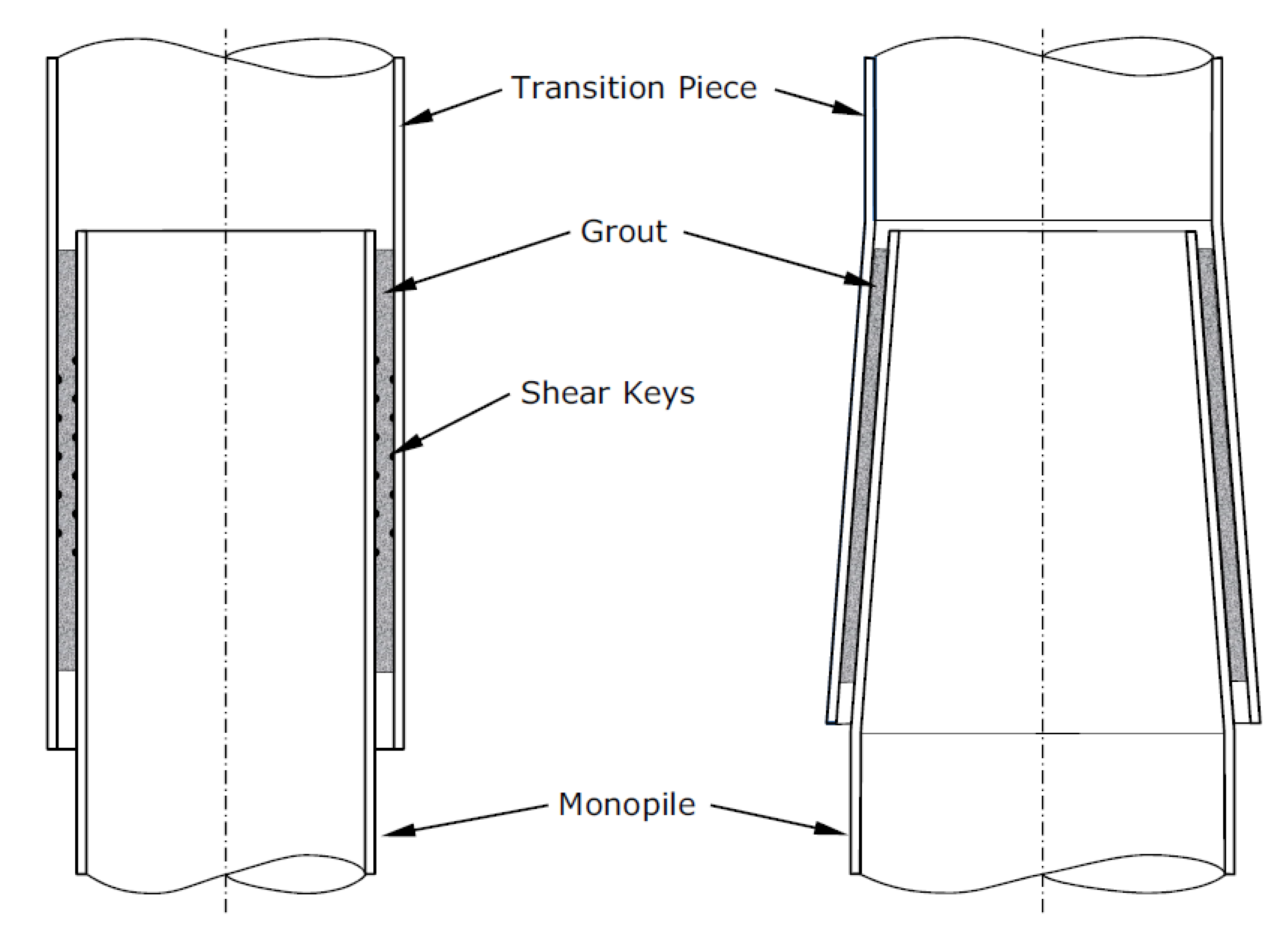
OWT structures, which are quite large in thickness and diameter, operate in the hostile marine environment, where variable amplitude loads are constantly applied on different parts of the structure [4,5]. In the offshore industry, grouted connections were initially used to charge the transition piece (TP), with a certain overlap length, on the monopile (MP) foundations. Therefore, there is a tube-in-tube connection, wherein the space between the two tubes is filled with grout (Figure 1) [6]. Towards the end of last decade, numerous grouted connection joints between large diameter monopiles and connecting tubular steel transition pieces at the base of overlying support towers were found to be failing. For the majority of U.K. offshore MPs that experienced grout cracking and failures, the issue was recognised to be primarily owing to the widespread absence of shear keys (or weld beads) on straight MP and TP surfaces. Bending moments as a result of complex wind (which was the main difference in loading conditions compared with oil and gas platforms) and wave loading were important design considerations that were not accounted for during design of grouted connections for OWTs. Furthermore, axial connection capacity was found to be significantly lower than that assumed previously owing to the MP scale effect, lack of manufacturing and installation tolerances, and abrasive wear due to the sliding of contact surfaces when subjected to large moments. Typical failure modes included dis-bonding, cracking, wear, and compressive grout crushing failure.
As a consequence of the above failures, the international accredited registrar and classification society withdrew the grouted connection certification. At different offshore wind farms, the zero-measurement was performed inside the confined space of each of the foundations, which showed an inclination of on average 1 to 2 mm (annual). Most cylindrical grouted connections without shear keys were retrofitted with elastomeric bearings capable of carrying the vertical loads at MP–TP connection elevation without significantly contributing to the moment capacity of the grouted connection [7]. The repair beared enormous economic consequences. For example, in Princess Amalia Wind Farm, after the design of the solution (a pilot repair case on one foundation), the repairing procedure was followed in all the remaining foundations, which involved a total investment of around €47 million.
The designers did not include shear keys because it was perceived as a cheaper and quicker option. The DNV J101 [8] OWT design code left it open to designers whether or not to use shear keys/weld beads. The use of annulus grouting allowed easier adjustment of the pile out-of-verticality using jacking to level the turbine tower prior to grouting. The use of “plain pipe” non-shear keyed connections is now discontinued, not recommended, and was essentially a systemic design error as a result of code phrasing omissions.
A second solution, conical grouted connections, has been extensively used on projects starting since 2009 (Figure 2) [9]. Some MP projects adopted designs without shear keys, including a 1- to 3-degree conical section that is presumed to be able to “catch” the TP as the grouted connection ultimately settles and drops, allowing radial stresses to be regained. This might be regarded by some as ‘controlled engineering for failure’. However, the use of conical TP sections is uncertain in the long term. MP ability to transfer large moments is complex, but has become better understood. Having said that, the design theories still have limitations and shortfalls.
A variety of alternative solutions were proposed by designers to solve the problems with pinned, clamped, and swaged connections, using shear keys or conical grouted connection without shear keys. The bolted flange is mostly adopted by the industry as a substitute for grouted connections and proved the most promising for further detailed investigation [10,11,12,13,14,15,16]. At present, bolted flange connection is one of the most common and critical mechanical joints within a wind turbine support structure. They join virtually all the wind turbine generator (WTG) towers to their foundations and are gradually becoming standard for MP to TP connections, particularly since problems with slipping grouted connections were discovered around 2010. In grouted connections, the use of shear keys was implemented to ensure that the slippage does not occur. However, it is a costly and time-consuming arrangement that can lead to fatigue problems. Bolted flanges avoid this issue altogether, and provide a direct load path through the primary steel alone. In parallel to the bolted flange connections, which are nowadays widely used in the offshore wind industry, an effort is being made to investigate the possible alternative solutions for MP-TP connection. Some examples are the single slip joint, double slip joint, and wedge connections, which are currently under development and testing at small scale. As a future trend in the offshore wind industry, it is expected that, upon successful completion of the alternative MP-TP connection concepts, a combination of different connection systems will be used in future generation of OWTs.
Some of the substantial benefits in implementation of bolted flanges in OWT MP–TP connections are as follows: (a) a direct load path where a joint can easily be inspected and monitored, (b) reduced steel requirements compared with grouted connections, and (c) the lack of need for curing time. Despite these significant benefits, there are some difficulties in bolted flange connections that need to be overcome. Bolted connections are sensitive to corrosion and must be robustly protected from the marine environment to ensure their longevity. Over time, bolt tensions can fall—particularly in the first months after installation—so accurate tensioning and monitoring equipment is necessary. A large number of bolts—sometimes more than 100 per connection—can make installation relatively lengthy, which can prove costly as offshore work costs are relatively high. Design criteria for exactly how much a flange can safely be allowed to open are also a hot topic to consider.
While the bolted flange is not a new development, there are clearly still many areas in which they can be improved. Ultimately, any improvements in methods—be that design, manufacturing, installation, operations and maintenance (O&M), or even decommissioning—can help reduce the cost of building and operating an offshore wind farm. Therefore, it is the aim of this study to identify the areas where the cost benefits can be gained most effectively through targeted review and research. In order to achieve the above aim, a comprehensive review is undertaken to identify the challenges and opportunities associated with flanges as well as bolted connections, and a few insights are put forward for consideration in future studies.

2. Offshore Wind Turbine Foundations

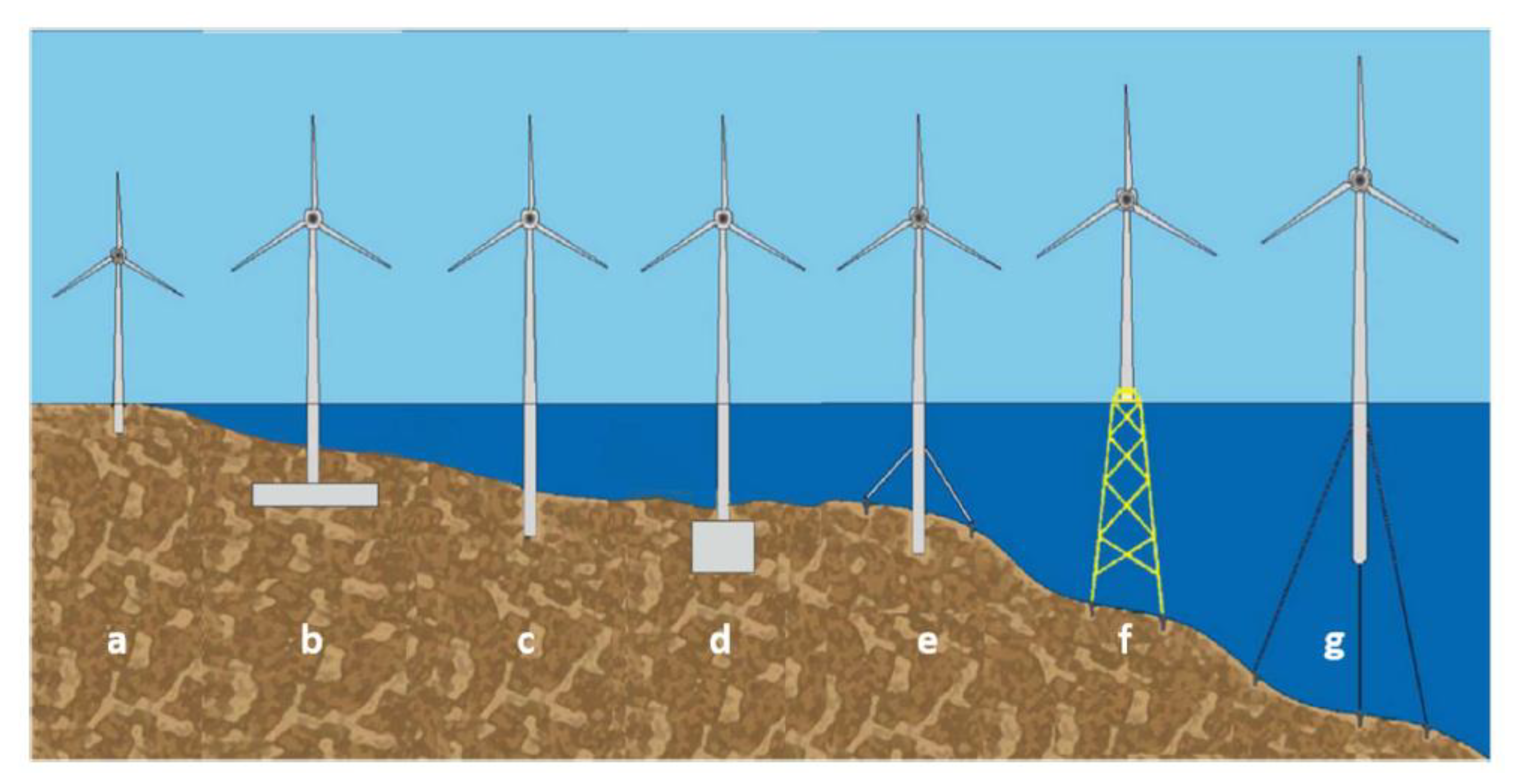
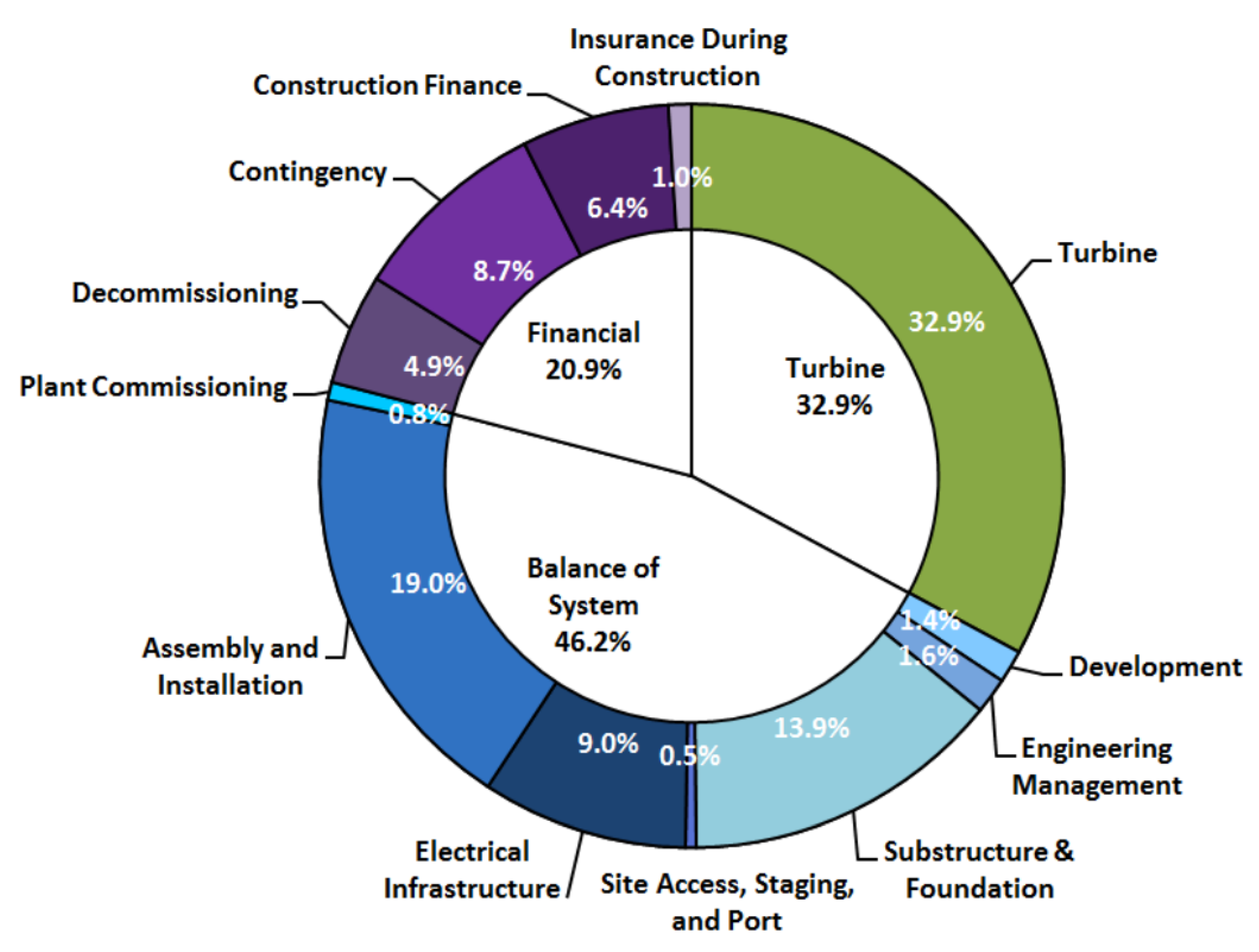
A brief description of different types of OWT foundations is provided in this section before specifically reviewing the issues related to bolted flanged connections in the subsequent sections. The different types of foundation structures of an OWT are shown in Figure 3 [17], and the characteristics of each type are listed in Table 1. The selection of one of these structures depends on a variety of factors such as the size of the turbine, the water depth, the sea bed’s type, and condition. Currently, of all installed OWT substructures in Europe, the monopile type accounts for over 80% of them [18]. A breakdown of the monopile foundation structure and its connection to the turbine’s tower can be seen in Figure 4 [7,9]. The tower that supports the turbine’s generator and rotor system are connected to the TP, which is mainly responsible for absorbing tolerances of any possible inclinations of the tower and simplifying its attachment to the monopile foundation. Furthermore, another use of the transition piece is to accommodate a small platform with which incoming vessels can be linked, for their crews to perform any necessary maintenance or inspection actions on the turbine. Further detailed explanations of the different types of foundations are not provided as it is not the main scope of the current study. Additionally, it is estimated that costs of the processes of assembly and installation along with the costs of the substructure and foundation account for 34% of the total capital expenditures of an offshore fixed-bottom wind farm project, as seen in Figure 5 [19]. Therefore, a price reduction in this area would imply a huge impact in cost cutting.

3. Bolted Flange Connections

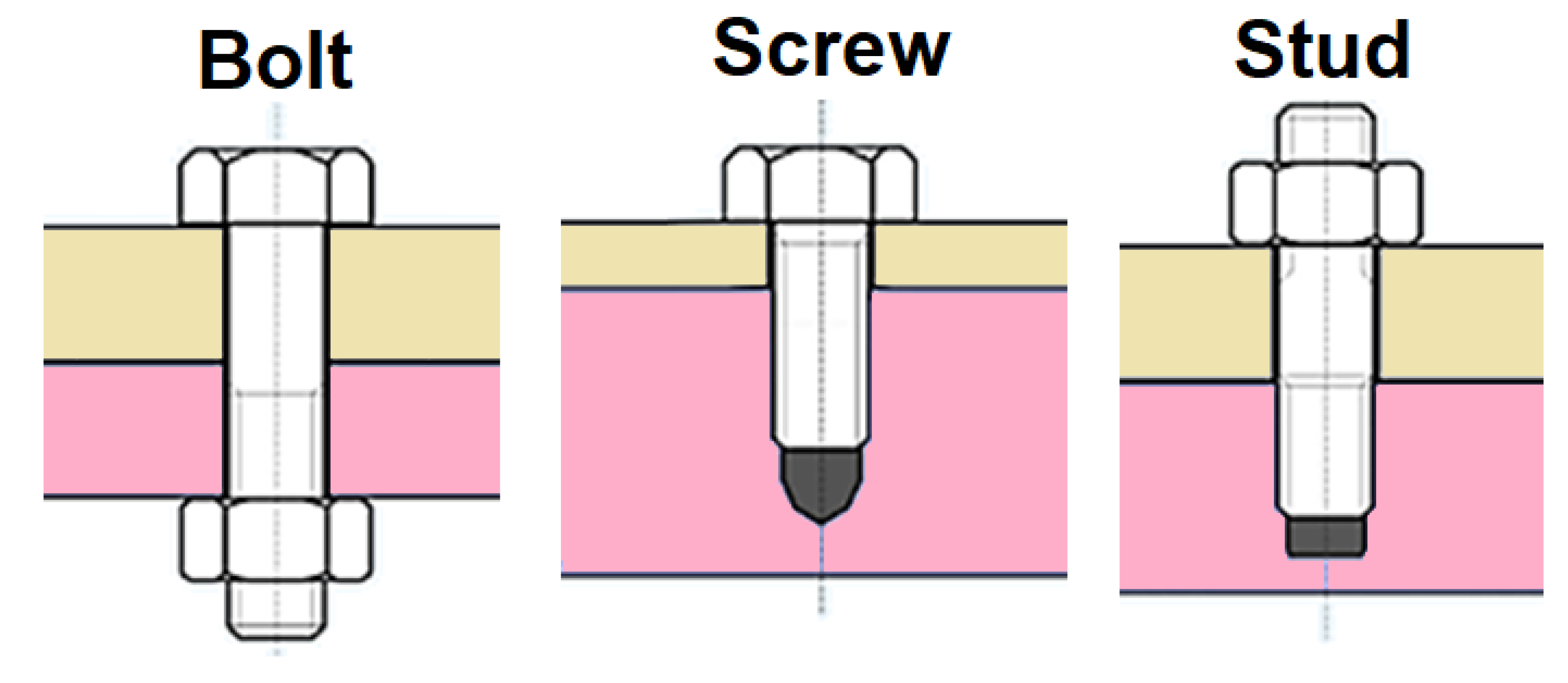
The bolt is defined as a type of threaded fastener with an external male thread, while the nut is a form of fastener with a threaded hole (Figure 6). Considering all factors mentioned previously, a sensible and feasible solution is the implementation of a bolted flange as the preferred method of MP–TP connection in OWTs. Bolted flange connection requires the two parts of the flange to be joined together by bolts that are equally spaced. The usual practice is to have the TP and MP ring flange with same outer and bolt circle diameter designed to withstand ultimate limit state (ULS) and fatigue limit state (FLS) in-place loads. The TP flange has an external extension to accommodate a skirt extending down to accommodate sacrificial anodes and boat landing. The annulus between the MP and the TP skirt has a rubber sealing at the bottom and in some designs is grouted for corrosion protection and stability of the skirt. It is proven that the joint grouted section with bolted flange design does not have any effect on the tolerance of the final loading. Therefore, filling concrete is not essential for structural safety. The flanges are connected with high-strength bolting assemblies. The flange and washer contact surfaces are treated with a thermally sprayed, metallised coating, and all other areas are corrosion protected by the epoxy coating.
The number of bolts depends on the flange radius and thickness, type of tool used, size of the bolts, and predicted loads on the structure. These bolts serve the purpose of exerting a clamping force to keep the joint together [20]. The behaviour and life of the bolted joint depend on the magnitude and stability of that clamping force. The preload is created by the tightening process during the assembly of bolt and nut in the joint to provide enough clamping force on the joint. Therefore, the bolts need to be preloaded at the assembly stage in the flange connection. An intuitive analogy would be to think of the bolts and the joint members as elastic parts. In that way, they can be modelled as spring elements, where the bolts are stretched in their elastic region when tightened, in order to compress the joint. The joint has a much stiffer elastic constant compared with the bolts, depending on material and dimensions.
It is possible to consider the bolt as an energy storage device, which accumulates the necessary potential energy to clamp the joint and is subjected to several environmental and operative conditions that may affect its behaviour [20]. The objective is for the preload on the bolt to be maintained at a certain level, but, owing to a large number of influencing factors, it is almost impossible to achieve or retain the desired state. It must be noted though, that the main concern is not the value of preload on the bolt, but maintaining the sufficient level of clamping force that holds the joint together. Moreover, if the clamping force is too low, the joint could loosen and be subjected to more severe consequences owing to cyclic loads. On the other hand, if the bolt is over-tight, it could exceed its proof load and may break under external load. In fact, during the tightening process, a torque is applied to turn the nut and the bolt stretches. This operation creates preload in the bolted joint. This sequence of events, at any point, controls the preload. It is possible to control the preload through torque or turn or stretch or through a combination of all of them. In all of the control strategies, the torque is used to tighten the fastener even if other mechanisms are used to control the tightening. There are a lot of uncertainties in the relationship between the control parameters like torque and the preload, which could be minimised by measuring and controlling the build-up of bolt tension. This is the motivation for creating the family of tools called bolt tensioners. Using the bolt tensioner is nowadays a common practice during the installation of offshore wind turbines.

4. Design Criteria for Bolted Joints

The factors to be accounted foe during design of bolted joints include thorough consideration of shapes, functions, dimensions, materials, service environment, and working loads. These factors vary across industries and, usually, every industry has its own characteristic or typical joint configuration. Common standards and guidelines used for the design of bolted joints in industry include the following: (a) Verein Deutscher Ingenieure (VDI); (b) ASME boiler and pressure vessel code; (c) guide to design criteria for bolted and riveted joints used for design of structural steel and shear joints, prepared by Kulak et al. [21]; and (d) joint design procedure developed by NASA for space shuttle and other joints.
In addition, the following criteria need to be given due consideration for the design of a full/part tensile joint: selection of materials that will ensure adequate clamping force to avert bolt self-loosening or fatigue, selection of bolts that can withstand the blend of maximum assembly stress and the maximum increase in stress due to service conditions as applied load and differential thermal expansion, bearing stresses created by bolts on the joint surfaces and bolt accessibility, and stiffness ratio of the joint. For the case of shear joints, it must be ensured that the bolts and joint members are not exposed to varying or cyclic loads, as this will lead to self-loosening and fatigue problems. Finally, another commonly observed tendency seen in various industries is to overdesign or oversize the bolt and joint members. The overdesigning is adopted to overcome the many assembly and service uncertainties. Further studies and developments can lead to the optimisation of the design, thereby bringing down the additional weights and costs associated with overdesign.

5. Challenges in Bolted Joints

There are numerous challenges associated with bolted joints and these may arise during assembly stage or in-service. These challenges are caused by numerous variables that influence the assembly process and the in-service behaviour of bolted joints. The variables changes in response to service and environmental conditions, which in turn affect the active energy of the bolts.

5.1. Challenges in the Assembly Process

The main aim of the assembly process is to ensure that the joint has adequate and optimal clamping force. As mentioned before, the clamping force introduces the first energy to the bolt and joint springs. It needs to be ensured that the clamping force is neither below nor over the optimal value because the longevity and behaviour of such joints depend on the optimal amount of clamping force. The clamping force is controlled by adjusting the amount of tension or preload in the bolt. For the torqueing applications, the assemblers control the clamping force by adjusting the torque applied to the nut or head. Theoretically, the kinetic energy on the fastener during tightening is equivalent to half of the applied torque multiplied by the angle, measured in radians, through which the nut turns [22]. During tightening, the work is done on the fastener, which is equal to the area under the torque turn curve (measured in N-m times radians). Ideally, all of this work would be converted to potential energy in the bolt. This means that all of the work on this fastener would end up contributing to the clamping force. Unfortunately and unavoidably, most of the inputted work is often lost. Typically, about 90% of the work on a bolt and nut is lost during the tightening, and only around 10% of the input work ends up as potential energy in the bolt; so only 10% ends up as bolt preload or as the clamping force between joint members. Therefore, only 10% of the kinetic energy (i.e., input work) gets converted to potential energy stored in the joint and bolt springs. The remaining 90% is lost in following forms: heat caused by friction among the nut and joint surface and among the male and female threads; energy lost to twisting and bending the bolt; energy lost to correcting the misalignment; and, finally, energy lost to nut dilation, whereby the energy is reduced owing to spreading the bottom of the nut. The major challenge faced by designers is to predict the individual percentage of losses caused by the above-mentioned factors.
Furthermore, a bolt loses more energy for a couple of other causes. The first cause is embedment and, subsequently, joint contact surfaces creep out from under initial contact pressure and the parts settle into each other [22]. The second cause is elastic interaction, whereby a bolt will relax owing to tightening of its neighbouring bolt [23]. This cause is even more challenging for the assembling process as it is more difficult to accurately forecast the relaxation caused. The above mentioned assembly challenges are applicable to both tension and shear joints.

5.2. Challenges during the Operational Phase

The challenges during in-service behaviour are different to those faced during the assembly process. During the assembly process, tensile and shear joints behave uniformly, whereas the in-service behaviour of tensile joints diverges considerably from that of shear joints. The tension in the bolts is increased owing to the application of tensile loads during in-service behaviour, which will lead to loss of clamping force between the joint members. This phenomenon is to be avoided as it is undesirable and it further reinforces the need of optimal bolt tension and clamping force during assembly. If the preloads are high, the bolts may yield or break owing to the exposure of service loads, while the low preloads result in disappearance of clamping force owing to the application of service load.
In addition, factors such as vibration, shock, and thermal cycles can cause the self-loosening of bolts in-service. Differential expansion and corrosion coupled with previously listed factors pose further challenges to the designer [24]. For example, it is challenging to accurately project the exact service loads the joints will face owing to the presence of corrosion products. In-service behaviour is also influenced by the preload in the bolts, which is to be defined by the designer. As a consequence of all these factors, a common trend observed in industries, especially in the design of airframes, bridges, or building structures, is to rely on shear joints instead of tension joints. By doing so, the effect of tension in the bolts or the clamping force between joint members can be minimised, as shear loads has little influence on them.

6. Specific Issues Associated with Bolted Joints

This section introduces some specific issues associated with bolted joints. The commonly observed key issues include material selection issues, short-term relaxation of bolts, issues associated with load distribution in threads, and static failure of bolted flange. The most commonly observed defects for bolt type M48 and above are thread size, pitch error, and dimensional issues. Some of the specific issues associated with bolted joints are explained in the following sub-sections.

6.1. Short-Term Relaxation of Individual Bolts

There is a wide variety of factors that can influence preload, so it is very challenging to have the desired value in practice. For example, in the torque control method, friction plays an important role as there can be huge differences even while using the same material, coating, or lubricant. The two most important contributing factors for observing lower than expected preload values are relaxation effect and elastic interaction. If the relaxation is for a short amount of time just after the application of the preload, it is known as short-term relaxation. The term “short” is used to distinguish it from the long-term effect that might occur. In fact, with short-term, one refers to the assembly process where external loads are not considered. This kind of relaxation involves some loss of preload just after the bolts are tightened. In general, it occurs when some contact surfaces of the joint go over the yield point and, subsequently, plasticity develops.
The main causes of short-term relaxation are the embedment, which occurs mostly as a result of surface irregularities, as well as low temperature creep, which is generally referred to as time-dependent elongation of the material under tension (i.e., the bolt). In fact, all the surfaces that make up the bolted joint, such as the threads of the bolt and nut, bolt’s head, washers, and so on, even when pre-treated, are never perfectly smooth. When the components are loaded, the contact area in the threads is very small compared with the joint area, and just a few points will make up the real contact surface owing to irregularity in surface roughness or other flaws that can affect the strength of the threads. It is clear that those points have to withstand huge loads; therefore, even if the material has been chosen to sustain those loads, it cannot withstand these extremely high-pressure values. Consequently, plastic deformation occurs until the contact surface becomes large enough to survive the load without leading to plasticity. It must be noted that an advantage of the torqueing process compared with the tensioning method is the smoothening of the contact surfaces owing to the turning action of the nut on the bolt. On the contrary, during tensioning, there is no tribological action and the load is transferred just when pressure is released.
There are also other factors concerning the bolt’s and nut’s quality of manufacturing processes and design, such as poor thread engagement, too short thread engagement, as well as soft parts that can lead to bending and plastic deformation. Moreover, any misalignment between the bolt and the flange’s hole can cause the bolt’s head to be extremely loaded and deformed. Furthermore, having undersized or oversized holes can lead to further relaxation. For undersized holes, the problem is located in the fillet, the transition part between the head and the body of the bolt, because with a smaller hole, the fillet compresses plastically the edge of the hole, leading to relaxation, whereas having a bigger hole leads to a smaller contact surface than required [20]. In this case, the relaxation depends on the nut or washer features. It has been estimated that short-term relaxation impacts the preload with a considerable relaxation right after the tightening procedure [21].

6.2. Bolt Material Selection

The selection of appropriate material for the bolt is another factor that needs to be given due consideration. To put it straightforward, the material is selected based on the bolt manufacturer sticking to product requirements and by the customer insisting on the conformance to the needs of the environment in which the bolt will be exposed. The main factors to be considered while selecting the material are the magnitude of the clamping force, stability or reliability of the clamping force, thermal expansion or contraction, corrosion, fatigue rupture, elastic stiffness of the parts, temperature effects, and cost. Materials usually have an endurance limit that is typically a fraction of its static tensile strength. If the periodic cyclic loads reach above the endurance limit, the clamping force will be lost owing to breaking of the bolt. For a given dimension, a stronger material indicates a stronger bolt. Therefore, choosing a material with high yield strength will inevitably increase the clamping force of the bolted joint. The flange connections in an offshore wind turbine are usually fabricated from 355 steel, but the bolts, washers, and nuts are made of high-strength steels.
Another important aspect to be considered is the effect of temperature while selecting the bolt material. If the parts of the joint (i.e., bolt and nut) are made from different materials, the clamping force on the joint and the tension in the bolts will be altered by differential thermal expansion or contraction. The consequence of this trend is multipronged as it can either increase or decrease the clamping force depending on the thermal expansion or contraction coefficient. On the other hand, even if the materials have similar thermal coefficients, very high temperature is not ideal for retaining the clamping force in the bolts. The high temperatures create stress relaxation, owing to pronounced time-dependent creep deformation, which usually takes place through a prolonged duration, thereby affecting the integrity of the clamping force.

6.3. Strength of the Threads

The threads form the inevitable part of any bolted joint connection. In the common practice, various inspection levels have been prescribed for threads based on the nature of the application and the consequences of failure. The point of contention across industries is on the type of bolts to be required to pass a particular type of test. ASME boiler and pressure vessel code [25] describes requirements specific to the design, fabrication, inspection, testing, and certification of threads. According to this code, various levels of inspection are specified. The least demanding is Level 21, which is designed to warranty functional assembly of male onto female threads and functional size control of maximum material limits [25]. The higher one, Level 22, has requirements for minimum material size bounds over the full length of engagement of the thread. The highest level, Level 23, has specific instructions to be met on thread flank angles, lead, taper, and roundness, in addition to fulfilling all the requirements of the lower levels.
The threads should be designed in such a way that the main body of bolted joint breaks before the failure of threads. This is needed because a broken bolt is easier to spot than a stripped thread. The extent of contact between male and female threads should not be minimised as it affects the strength of threads. The misalignments decrease the resistance of a bolt to shock or vibration, thereby boosting self-loosening; therefore, it should be avoided as far as possible.

7. Miscellaneous Setups Associated with Bolts and Failure Mechanisms

The aim of this section is to shed inputs into various setups related to bolted joints. These setups include washers, lubricants, fastener coatings, gasket, and shimming. In addition, a few important failure mechanisms associated with bolted joints are explained and discussed.

7.1. Washers

Washers play a pivotal role in creating and maintaining the integrity in bolted joints. They perform a variety of functions such as averting damage to the surface contiguous to the bolt, avoiding head embedment, acting as a locking mechanism, and spanning misfit holes. Washers, especially flat washers, can be employed in the connection between the flange and the bolt’s head to achieve a more uniform load distribution, as the fastener is being tightened. Different types of washers can be employed at the joint to investigate the effect of size and thickness of washers on preload. An increase in the size of the washer decreases the strength at the joint [26]. Moreover, Belleville washers of conical shape behave like springs deforming under load application. This kind of washer is particularly useful to keep the tension constant, during the joint’s service life, even if dimensional changes occurs owing to relaxation, thermal changes, or wear [27]. The lack of washers will produce high stress values in the proximity of the hole bearing the bolt, which significantly influences the integrity of the bolted connection. This is because the washers will distribute the forces more uniformly, while taking high stresses themselves. However, they are one-use only, so plasticity can be assumed as a standard operational issue.

7.2. Lubricants

Lubricants are applied to fasteners to provide uniform values of friction coefficient by creating a thin film of lubricant between the surfaces (bolt and nut’s thread, under the bolt’s head/washer, and the nut/washer). Thus, while applying the preload on the fastener, it minimises the part of the scatter of preload values that is caused by the non-uniform values of friction coefficients of unlubricated surfaces. It is important to mention, though, that this effect is mainly observed in situations where the preload is applied with the use of torque on the head or the nut. In cases where the tensioning method is utilised, the influence of lubricants is still a matter of further study. Types of lubricants that are currently used in various industries are oil, grease, and solid film lubricants. In the literature, there has been thorough study about their effects on bolted connections and, in particular, on the relationship between applied torque and acquired bolt tension [28,29,30,31]. Additionally, their beneficial effects in countering self-loosening effects of bolts under dynamic shear loading conditions have been presented by Zhou et al. [32]. An additional requirement that a lubricant must fulfil in an environment like the one of an OWT is to have anticorrosive action, thereby protecting the bolted surfaces. The most common lubricants for bolts in these kinds of operating conditions are PTFE (polytetrafluoroethylene) or MoS2 (molybdenum disulphide) based coatings that are used for lubrication purposes.

7.3. Coatings

The purpose of coating is to make the bolt resistant to the environmental damage such as corrosion, and the choice of coatings varies for different industries. In the petrochemical industry, stainless steel is the preferred choice, whereas in the aerospace industry, it is inconel and titanium [33]. Aluminium and plastics are common in automotive industry, while silicon bronze, monel, and titanium are used in marine structures. It is worth noting that, despite the attractiveness of corrosion-resistant based materials, a widespread way to shield bolts is to coat them with a protective layer. Broadly, organic coatings enable twice the corrosion protection compared with cadmium or zinc plating. In addition, they eradicate the hydrogen embrittlement problems occasionally instigated by the electroplating process.

7.4. Gaskets and Shimming

A gasket is the interface between two imperfect surfaces. Its function is to prevent leakage of liquids or gases under constantly changing conditions of mechanically and thermally induced stresses. Gaskets are used in static sealing applications that range from a simple rubber seal on a garden hose to sophisticated combinations of metallic and non-metallic elements for high pressure, high-temperature industrial applications, often sealing toxic or flammable liquids or gases. Gaskets may be specially designed for a particular application, such as an automotive cylinder head gasket, or they may be manufactured to fulfil requirements according to different standards. Those standards specify dimensions; materials of construction; pressure/temperature classes; and, in some instances, methods of construction and methods of identification marking. A shim is a type of gasket that is usually thin and is commonly tapered or wedged between pieces of materials. The main function of a shim is to occupy small gaps or spaces between objects, thereby providing a level surface.
Gaskets would not be necessary if the faces of flanges were perfectly flat and parallel to each other and stayed that way during operation. However, in practice, the flange surfaces are always rough and out of parallel to some degree. Furthermore, the relationship of the flanges, one to the other, changes during assembly and while in operation. This unevenness must be compensated by a compressible and recoverable material. In addition to the sealing material acting as a compensator for flange imperfections, it must also act as a barrier against the medium inside the pipe, and thus be chemically resistant to that medium and the temperatures encountered. The gasket must also have a load-bearing capacity sufficient to sustain the stress coming from the bolt forces and the internal pressure. In summary, a good gasket must be conformable to flange surfaces; must exhibit resistance to high temperatures, high surface pressure, and chemical attack; and must remain tight at all service conditions.
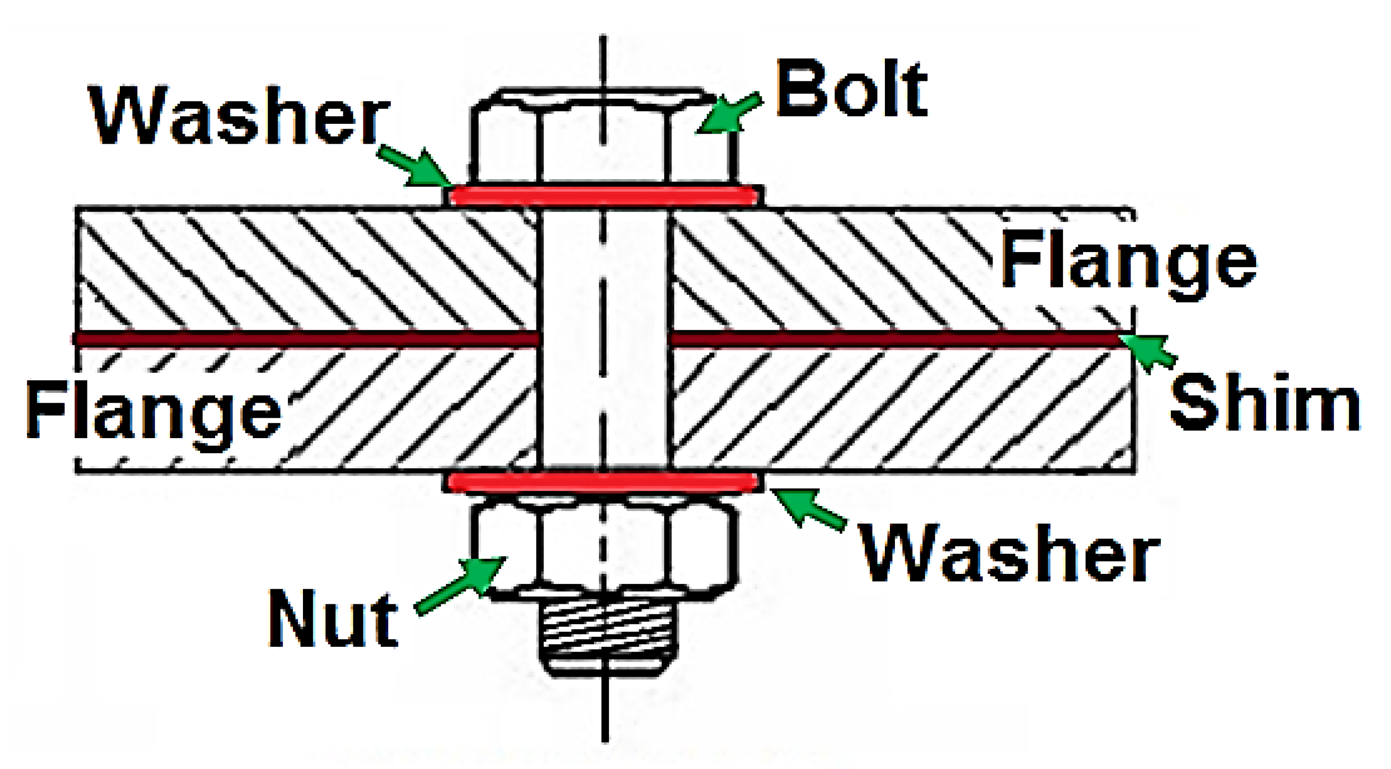
The typical flange connection details are depicted in Figure 7. In the past, the gaskets were not considered a critical element in the plant design. When a leak did occur, it was always assumed to be the fault of the gasket and never of incorrect flange design or incorrect gasket installation. Very basic reasons often lead to leakage in a bolted flange connection, and in most cases, it is not the gasket itself that causes the problem. Failure of gasket in flange occurs by misalignment of the gasket; rotation of flanges and gasket materials; and design factors such as insufficient bolt load (low gasket stress), excessive bolt load (high gasket stress), and weak flange/poor bolting arrangement.

7.5. Self-Loosening

When a bolt is tightened, the energy will be pumped into it and the bolt acts as a stiff spring that could be stretched, twisted, or bent. This pumped energy is detained in the bolt by friction constraints in the threads or between contact faces of the nut and the joint [22]. Self-loosening happens when this stored energy is released as the result of overcoming of above mentioned friction forces by any means. There are various theories and previous works on the reason for self-loosening of bolts through vibration, thermal cycles, and thermal shock [34,35,36,37,38,39,40,41,42,43]. Broadly speaking, the works agree that, unless an external load acts on the bolted joint, the frictional forces will remain intact.
The various ways to ensure the integrity of the joints against self-loosening include keeping the external forces lower than the frictional forces, introducing mechanical prevention of slip, and offering a counter torque or locking action against external mechanisms. When a counter torque or locking action is offered, the following factors need to be taken care of: operating temperature limits, mating thread accommodation, reusability, type of installation tools required, and the change in the mechanical properties of mating parts. Sometimes, it is impossible to provide enough prevailing torque to prevent loosening under severe load shock or vibration conditions; on the other hand, the safety factor is specified to be absolutely sure that the fasteners will not be lost. In such situations, it is possible to consider the use of clips in which the nut and bolt are mechanically locked together (using, for example, lock wires and pins, welding, stage 8 fastening system, Huck lockbolt, Honeybee robotics, A-lock bolt and nut, and Omni-lok fasteners).

7.6. Fatigue Failure

The essential factors that are critical for fatigue failure to occur in bolted connections are the presence of a vulnerable material, initial crack/flaw in the material, cyclic tensile loads, and stress levels above the fatigue endurance limit. There have been considerable studies exploring the effect of various parameters on fatigue life in bolt and nut [44,45,46,47,48,49,50,51,52]. Fatigue failure has consequences owing to the fact that the reduction in clamping force in a particular bolt will make neighbouring bolts susceptible to failure, thereby initiating a chain action. If a flaw/crack is present in the bolt material, the sequence of fatigue failure is as follows: crack initiation, crack propagation, and final rupture [53].
In order to reduce or minimise fatigue failure in a bolted joint, the straightforward approach is to ensure the presence of an optimised preload. This will prevent the opening of flaws by external forces by acting as a counter force to external action. There are other specific ways to minimise fatigue problems observed in bolted joints. Using a large thread root radius will eliminate sharp corners that facilitate the fatigue crack initiation and growth. Similarly, rolling the threads as an alternative to cutting them ensures a smooth surface, which inhibits fatigue crack initiation and growth owing to the formation of a layer of compressive residual stresses at the threads. The use of fillets and flanged heads discourages the growth of flaw by reducing stress concentrations and improving stress distributions, respectively. Geometrically, it is advisable to keep the underside of the bolt head and the joint surfaces perpendicular to thread axes and bolt holes. Regarding specifications for thread, the runout should be smooth instead of rough, and it is recommended to reduce the number of active thread heads as it will aid in decreasing the stress concentration.

7.7. Corrosion

Corrosion in bolted joints is a vast topic to be covered in a single section and, therefore, a brief summary of previously published works relevant to offshore wind industry is mentioned here [54,55,56,57,58,59,60,61,62]. Bolted joints in the offshore wind industry are even more prone to corrosion as they are continuously exposed to marine environment [63,64]. Corrosion damage has a direct link with fatigue failure as they complement each other, and corrosion accelerates fatigue crack initiation and propagation [65,66]. The key factors in the offshore wind industry include lack of over-tap allowance on the nut thread to account for coating thickness and selection of inappropriate coating systems. Furthermore, corrosion results in loss of preload over time. Typical corrosion protection systems used in WTG bolted flange connections include zinc surface treatments (i.e., hot dip galvanisation/zinc plate/zinc-nickel plating), PTFE coatings, marine paints, and ceramic–metal (CerMet) coatings [67]. Some of the possible suggestions to improve the corrosion resistance of the bolted flange connections are as follows: (a) selection of appropriate coating systems, (b) giving due consideration to coating thicknesses when designing joints, (c) increase certainty of load levels at initial installation, and (d) use think film coating systems that deliver a consistently low coefficient of friction without the need for installation aids such as oils and greases.

7.8. Galling

Another mode of failure that is not common in occurrence in the presence of corrosion, but is significant if it occurs, is galling. By definition, galling is the tear and gouge of thread surfaces owing to breakage of the atomic bonds between them. These atomic bonds are formed when the surfaces of male and female threads happen to be in close contact under high contact stress, and this trend is typically observed in large bolts [68]. The factors aiding galling include non-existence of lubrication, absence of oxide film on the metal, high contact pressure, and heat. As per the authors’ inference, none of the previous studies reveal a specific solution to address the galling issues [68,69,70,71]. However, the following techniques may assist in reduce galling: (a) usage of coarse threads as a substitute for fine threads and (b) usage of good thread lubricant or anti-seize compound such as Moly disulphide, FelPro C670 lubricant, silver-based lubricants, milk of magnesia, silicon grease, and liquid dish detergent. In addition, material combinations such as stainless steel nuts on low-alloy bolts and cold-drawn 316 stainless steel with cold-drawn 316 bolts aid in galling reduction.

7.9. Inspection and Maintenance of Bolted Connections

A peek into salient aspects regarding inspection and maintenance for bolted connections used is provided in this section, with particular emphasis on offshore wind applications. Different experimental protocols based on testing multiple factors in a planned sequence of runs are used to help designers, manufacturers, and operators to find the best results during operation and maintenance. Various specifications (such as those for defence applications, nuclear industry, aerospace association, automotive industry, and structural committee) choose the relevant inspection programme regarding the purpose for which the bolts are used. The techniques used include visual inspection, magnetic particle, ultrasonic equipment, smart washers, and various type of wrenches. In spite of the technique used, a skilled inspector is necessary to ensure the quality of the employed approach. Coming specifically to the offshore wind industry, there is an interest in “torque-to-yield” systems, though the benefits are not fully understood yet by the developers. Bolt tension monitoring is promising, but it would be preferable for ‘fit and forget’ type flange connections. Some developers use ultrasonic tension measurements to plot graphs of relaxation over time. It is recommended to avoid heavy lifting offshore (particularly relevant for large bolts, for example, M72) for health and safety reasons. In addition, considering time, cost, and vessel mobilisation factors, it is preferable to avoid offshore grouting operations.

8. Discussion

This section undertakes a discussion on possible ways to address the issues and concerns associated with bolted flange connections. The authors wish to make it clear that the possible suggestions mentioned in this section are by no means the precise solutions to all the identified issues in the paper; rather, they serve as a platform from which further investigations/studies can be carried out. Broadly speaking, the scope of these potential improvements is enormous, and these improvements could have a significant effect on various aspects related to design, operation, and maintenance of bolted connections in offshore wind farms.
One major avenue that can be explored is the widespread use of the tensioning method compared with torqueing, as it is likely to give more consistent tension in bolted connections. Another aspect that can be considered in design is reducing the distance from the bolt centreline to the centreline of the tower shell as much as possible. For flange improvement, it would be ideal if the installation conditions are defined in such a way to keep the bolted connection as maintenance-free as possible. From a durability point of view, the seals should protect the bolted connection from seawater for the entire duration of the lifetime.
As mentioned in the previous sections, installers often face different changes compared with designers. A few possible avenues that could help in smooth installation are consideration of practical issues of installation at the design stage and not as an afterthought, specification of larger bolts by designers, allowing the use of more portable tools when installing in a confined space, increasing bolt quality/consistency of material properties for larger bolts, developing specific flange standards, and yield controlled bolt tightening. Furthermore, the force characteristics of the hammer can be optimised to reduce peak stresses in the flange, reduce fatigue stresses in the flange, and reduce noise emissions during piling operations.
Similarly, there are various methods to improve the fabrication of bolted connections for application in the offshore wind industry. These include reducing the tolerance requirements for manufacturers to improve cost and time constraints, aligning design with production methods, and reducing neck lengths where possible. It is worth noting that, for neck lengths below 50 mm, it becomes cumbersome to weld to cans as there is insufficient room for equipment/weld preparation. Keeping flange designs simple could greatly aid in hassle-free fabrication such as the design of rectangular flanges and welded rather than forged flanges. A further process of simplification can be carried out by avoiding complex sealing details and eliminating machining of the flanges after delivery from a specialist supplier.
Proper feedback of installation experience to design teams is essential to allow a reduction in design conservatisms such as low friction coefficients, high scatter factors for bolt tension, and conservative flange load distributions. Possible avenues can be explored to reduce the number of bolts as well as required tensioning by optimising the design of bolted flange connections. Semi-automatic or automated tensioning systems and automated hydraulic torque tension systems could be used. Such systems will make it easy for a technician to identify which bolt to attach the system to next and should automatically record/evaluate the required torque levels as it progresses around the flange. A fully automated system would be able to move around the flange itself and perform bolt tightening. It should also be able to check tensions as it moves around the flange and calculate/correct its torque values or tensioning pressure to ensure minimum scatter in preload values on individual bolts. Removing the requirement for washers with careful design can be given deep thought, and the weight of hardware and/or tooling required for bolt installation should be minimised. For time saving, decreasing the number of bolted joints or the time required to install in difficult to access areas and reducing manual torqueing/tensioning are recommended. It is certainly preferable to design the bolt for optimum preload levels, and use instrumented bolts/nuts to enable continual monitoring of bolt preload and re-tightening if essential.
The authors would wish to put forward certain research topics that may be investigated in future work. These include investigation of the corrosion process in the bolts in the case of a seal failure, investigation of the risk mitigation measures in the case of corroding bolts, improvement of modelling approaches, understanding of bolt bending during pre-tensioning, investigation of the necessary condition to allow for a plastic deformation for bolt capacity analysis under ultimate limit state conditions, and finally understanding if there is a negative influence on bolt durability in the case where a torque-to-yield installation method is used.

9. Conclusions

The employment of bolted flange connections for OWTs has considerably increased in the past decade owing to the failures and subsequent economic losses associated with grouted connections. In this study, the issues and opportunities associated with bolted flange connections have been thoroughly reviewed and discussed for application in the offshore wind industry. The key conclusions drawn from this study are as follows:
  • The advantages of bolted flange connections include the provision of direct load path through the primary steel alone, thereby avoiding slippage, reducing steel requirements compared with grouted connections, the absence of curing time, and easiness to inspect and monitor the MP–TP connection.
  • The challenges associated with bolted flange connections include material selection issues, short-term relaxation of bolts, issues associated with load distribution in threads, and static failure of bolted flange.
  • The main cause of short-term relaxation is the embedment that occurs mostly owing to surface irregularities as well as time-dependent creep deformation.
  • The consequence of temperature differential can either increase or decrease the clamping force depending on the thermal expansion and contraction coefficient of the materials employed in bolted connections.
  • The setups associated with bolted joint such as washers, lubricants, coatings, and gaskets play a pivotal role in creating and maintaining integrity in bolted joints.
  • The failure modes observed in bolted joints include self-loosening, fatigue failure, corrosion, and galling.
  • An expected trend in the bolted flange connection is the increased usage of tensioning tools compared with torqueing applications.
  • Further studies in the offshore wind industry can enable the optimal use of bolted flange connections in design, manufacturing, installation, operation, maintenance, and decommissioning phases.

Author Contributions

A.M.: conceptualisation, supervision, writing—review and editing; S.L.: methodology, investigation, writing; S.P.V.: investigation, writing. All authors have read and agreed to the published version of the manuscript.

Funding

This work was supported by the Centre for Advanced Materials for Renewable Energy Generation (CAMREG) under grant number EP/P007805/1 from the U.K. Engineering and Physical Sciences Research Council (EPSRC).

Conflicts of Interest

The authors declare no conflict of interest.

References

  1. Ambrose, J. Offshore Wind to Power £17.5bn Investment Boom as Costs Halve. Available online: https://www.telegraph.co.uk/business/2017/09/11/offshore-wind-power-175bn-investment-boom-costs-halve (accessed on 1 August 2018).
  2. Hundleby, G.; Freeman, K. Unleashing Europe’s Offshore Wind Potential: A New Resource Assessment; BVG Associates: Brussels, Belgium, 2017; Volume 64. [Google Scholar]
  3. Kay, A. Cost Reduction Monitoring Framework 2016; Summary Report of the Offshore Wind Programme Board; ORE Catapult: Glasgow, UK, January 2017. [Google Scholar]
  4. Mehmanparast, A.; Brennan, F.; Tavares, I. Fatigue crack growth rates for offshore wind monopile weldments in air and seawater: SLIC inter-laboratory test results. Mater. Des. 2017, 114, 494–504. [Google Scholar] [CrossRef] [Green Version]
  5. Mehmanparast, A.; Taylor, J.; Brennan, F.; Tavares, I. Experimental investigation of mechanical and fracture properties of offshore wind monopile weldments: SLIC interlaboratory test results. Fatigue Fract. Eng. Mater. Struct. 2018, 41, 2485–2501. [Google Scholar] [CrossRef]
  6. Lotsberg, I.; Serednicki, A.; Lervik, A.; Bertnes, H. Design of grouted connections for monopile offshore structures. Stahlbau 2012, 81, 695–704. [Google Scholar] [CrossRef]
  7. Gollub, P.; Jensen, J.F.; Giese, D.; Güres, S. Flanged foundation connection of the offshore wind farm Amrumbank West—Concept, approval, design, tests and installation. Stahlbau 2014, 83, 522–528. [Google Scholar] [CrossRef]
  8. DNVGL. DNV-OS-J101—Rules and Standards, Design of Offshore Wind Turbine Structures; Det Norske Veritas: Oslo, Norway, 2007. [Google Scholar]
  9. DNVGL. DNVGL-RP-0419, Analysis of Grouted Connections Using the Finite Element Method; DNVGL: Oslo, Norway, 2016. [Google Scholar]
  10. Oechsner, M.; Beyer, J.; Simonsen, F.; Schaumann, P.; Eichstädt, R. Experimental and analytical assessment of the fatigue strength of bolts with large dimensions under consideration of boundary layer effects. In Proceedings of the METEC & 2nd European Steel Technology and Application Days, Düsseldorf, Germany, 15–19 June 2015; pp. 1–6. [Google Scholar]
  11. Schaumann, P.; Seidel, M. Failure analysis of bolted steel flanges. In Proceedings of the Seventh International Symposium on Structural Failure and Plasticity (IMPLAST2000), Melbourne, Australia, 4–6 October 2000. [Google Scholar]
  12. Schaumann, P.; Eichstädt, R. Fatigue assessment of high-strength bolts with very large diameters in substructures for offshore wind turbines. In Proceedings of the Twenty-fifth International Ocean and Polar Engineering Conference. International Society of Offshore and Polar Engineers, Kona, HI, USA, 21–26 June 2015. [Google Scholar]
  13. Schaumann, P.; Marten, F. Fatigue resistance of high strength bolts with large diameters. In Proceedings of the International Symposium for Steel Structures ISSS, Seoul, Korea, 12–14 March 2009; Volume 12, pp. 1–8. [Google Scholar]
  14. Madsen, C.A.; Kragh-Poulsen, J.C.; Tage, K.J.; Andreassen, M.J. Analytical and numerical investigation of bolted steel ring flange connection for offshore wind monopile foundations. In IOP Conference Series: Materials Science and Engineering; IOP Publishing: Bristol, UK, 2017; Volume 276, p. 012034. [Google Scholar]
  15. Leite, O.B. Review of Design Procedures for Monopile Offshore Wind Structures. Ph.D. Thesis, Faculdade de Engenharia da Universidade do Porto, Porto, Portugal, June 2015. [Google Scholar]
  16. Ng, C.; Ran, L. Offshore Wind Farms: Technologies, Design and Operation; Woodhead Publishing: Duxford, UK, 2016. [Google Scholar]
  17. Wang, X.; Zeng, X.; Li, J.; Yang, X.; Wang, H. A review on recent advancements of substructures for offshore wind turbines. Energy Convers. Manag. 2018, 158, 103–119. [Google Scholar] [CrossRef]
  18. Pineda, I.; Tardieu, P. The European offshore wind industry—Key trends and statistics 2016; European Wind Energy Association: Brussels, Belgium, 2016. [Google Scholar]
  19. Stehly, T.; Heimiller, D.; Scott, G. 2016 Cost of Wind Energy Review; Technical Report for National Renewable Energy Laboratory (NREL); NREL: Denver, CO, USA, 2017.
  20. Bickford, J.H. An Introduction to the Design and Behavior of Bolted Joints, 4th ed.; CRC Press: New York, NY, USA, 2008. [Google Scholar]
  21. Kulak, G.L.; Fisher, J.W.; Struik, J.H. Guide to Design Criteria for Bolted and Riveted Joints, 2nd ed.; AISC: Chicago, IL, USA, 2001. [Google Scholar]
  22. Bickford, J.H. Introduction to the Design and Behavior of Bolted Joints, Non-Gasketed Joints, 3rd ed.; CRC Press: New York, NY, USA, 1995. [Google Scholar]
  23. Braithwaite, J.; Mehmanparast, A. Analysis of Tightening Sequence Effects on Preload Behaviour of Offshore Wind Turbine M72 Bolted Connections. Energies 2019, 12, 4406. [Google Scholar] [CrossRef] [Green Version]
  24. Dehghani, A.; Aslani, F. A review on defects in steel offshore structures and developed strengthening techniques. Structures 2019, 20, 635–657. [Google Scholar] [CrossRef]
  25. ASME. ASME BPVC Section III. Rules for Construction of Nuclear Facility Components; ASME: New York, NY, USA, 1963. [Google Scholar]
  26. Kadam, A.N.; Ingale, S.M. Experimental and numerical analysis of effect of washer size and preload on strength of double lap double bolted GFRP-to-steel joint. Int. J. Sci. Res. 2017, 6, 2397–2402. [Google Scholar]
  27. Shigley, J.E.; Mischke, C.R. Standard Handbook of Machine Design, 2nd ed.; McGraw-Hill: New York, NY, USA, 1996. [Google Scholar]
  28. Zou, Q.; Sun, T.S.; Nassar, S.A.; Barber, G.C.; Gumul, A.K. Effect of lubrication on friction and torque-tension relationship in threaded fasteners. Tribol. Trans. 2007, 50, 127–136. [Google Scholar] [CrossRef]
  29. Hashimura, S.; Komatsu, K.; Otsu, T.; Sekido, Y. Influences of lubricants and bearing surface configuration under bolt head on self-loosening of bolted joints. J. Jpn. Soc. Tribol. 2017, 62, 205–216. [Google Scholar]
  30. Croccolo, D.; De Agostinis, M.; Vincenzi, N. Influence of tightening procedures and lubrication conditions on titanium screw joints for lightweight applications. Tribol. Int. 2012, 55, 68–76. [Google Scholar] [CrossRef]
  31. Gansheimer, J.; Wessely, J. Lubrication of threads. Wear 1980, 65, 201–206. [Google Scholar] [CrossRef]
  32. Zhou, J.; Liu, J.; Ouyang, H.; Cai, Z.; Peng, J.; Zhu, M. Anti-loosening performance of coatings on fasteners subjected to dynamic shear load. Friction 2018, 6, 32–46. [Google Scholar] [CrossRef] [Green Version]
  33. Tronci, G.; Marshall, M.B. Understanding the behaviour of silver as a low friction coating in aerospace fasteners. Tribol. Int. 2016, 100, 162–170. [Google Scholar] [CrossRef]
  34. Jiang, Y.; Zhang, M.; Lee, C.H. A study of early stage self-loosening of bolted joints. J. Mech. Des. 2003, 125, 518–526. [Google Scholar] [CrossRef]
  35. Zhang, M.; Jiang, Y.; Lee, C.H. Finite element modelling of self-loosening of bolted joints. J. Mech. Des. 2007, 129, 218–226. [Google Scholar] [CrossRef]
  36. Stephen, J.; Marshall, J.M.; Lewis, R. Relaxation of contact pressure and self-loosening in dynamic bolted joints. Proc. Inst. Mech. Eng. Part C J. Mech. Eng. Sci. 2016, 231, 3462–3475. [Google Scholar] [CrossRef]
  37. Gong, H.; Liu, J. Some factors affecting the loosening failure of bolted joints under vibration using finite element analysis. Proc. Inst. Mech. Eng. Part C J. Mech. Eng. Sci. 2017, 232, 3942–3953. [Google Scholar] [CrossRef]
  38. Liu, J.; Ouyang, H.; Feng, Z.; Cai, Z.; Liu, X.; Zhu, M. Study on self-loosening of bolted joints excited by dynamic axial load. Tribol. Int. 2017, 115, 432–451. [Google Scholar] [CrossRef]
  39. Dinger, G.; Friedrich, C. Avoiding self-loosening failure of bolted joints with numerical assessment of local contact state. Eng. Fail. Anal. 2011, 18, 2188–2200. [Google Scholar] [CrossRef]
  40. Yokoyama, T.; Olsson, M.; Izumi, S.; Sakai, S. Investigation into the self-loosening behavior of bolted joint subjected to rotational loading. Eng. Fail. Anal. 2012, 23, 35–43. [Google Scholar] [CrossRef]
  41. Pai, N.G.; Hess, D.P. Experimental study of loosening of threaded fasteners due to dynamic shear loads. J. Sound Vib. 2002, 253, 585–602. [Google Scholar] [CrossRef]
  42. Zadoks, R.I.; Yu, X. An investigation of the self-loosening behaviour of bolts under transverse vibration. J. Sound Vib. 1997, 208, 189–209. [Google Scholar] [CrossRef]
  43. Marshall, M.B.; Lewis, R.; Howard, T.; Brunskill, H. Ultrasonic measurement of self-loosening in bolted joints. Proc. Inst. Mech. Eng. Part C J. Mech. Eng. Sci. 2012, 226, 1869–1884. [Google Scholar] [CrossRef]
  44. Chakherlou, T.N.; Oskouei, R.H.; Vogwell, J. Experimental and numerical investigation of the effect of clamping force on the fatigue behaviour of bolted plates. Eng. Fail. Anal. 2008, 15, 563–574. [Google Scholar] [CrossRef]
  45. Majzoobi, G.H.; Farrahi, G.H.; Habibi, N. Experimental evaluation of the effect of thread pitch on fatigue life of bolts. Int. J. Fatigue 2005, 27, 189–196. [Google Scholar] [CrossRef]
  46. Korin, J.; Perez, I. Experimental evaluation of fatigue life and fatigue crack growth in a tension bolt–nut threaded connection. Int. J. Fatigue 2011, 33, 166–175. [Google Scholar] [CrossRef]
  47. Mínguez, J.M.; Vogwell, J. Effect of torque tightening on the fatigue strength of bolted joints. Eng. Fail. Anal. 2006, 13, 1410–1421. [Google Scholar] [CrossRef]
  48. Wei, J.; Jiao, G.; Jia, P.; Huang, T. The effect of interference fit size on the fatigue life of bolted joints in composite laminates. Compos. Part B Eng. 2013, 53, 62–68. [Google Scholar] [CrossRef]
  49. Leander, J.; Wadi, A.; Pettersson, L. Fatigue testing of a bolted connection for buried flexible steel culverts. Arch. Inst. Civil Eng. 2017, 23, 153–162. [Google Scholar] [CrossRef]
  50. Jiménez-Peña, C.; Talemi, R.H.; Rossi, B.; Debruyne, D. Investigations on the fretting fatigue failure mechanism of bolted joints in high strength steel subjected to different levels of pre-tension. Tribol. Int. 2017, 108, 128–140. [Google Scholar] [CrossRef]
  51. Grabon, W.A.; Osetek, M.; Mathia, T.G. Friction of threaded fasteners. Tribol. Int. 2018, 118, 408–420. [Google Scholar] [CrossRef]
  52. Lochan, S.; Mehmanparast, A.; Wintle, J. A review of fatigue performance of bolted connections in offshore wind turbines. Procedia Struct. Integr. 2019, 17, 276–283. [Google Scholar] [CrossRef]
  53. Igwemezie, V.; Mehmanparast, A.; Kolios, A. Current trend in offshore wind energy sector and material requirements for fatigue resistance improvement in large wind turbine support structures—A review. Renew. Sustain. Energy Rev. 2019, 101, 181–196. [Google Scholar] [CrossRef] [Green Version]
  54. Ahn, J.H.; You, J.M.; Huh, J.; Kim, I.T.; Jeong, Y.S. Residual clamping force of bolt connections caused by sectional damage of nuts. J. Constr. Steel Res. 2017, 136, 204–214. [Google Scholar] [CrossRef]
  55. Brown, W.; Long, S. Acceptable levels of corrosion for pressure boundary bolted joints. In Proceedings of the ASME Pressure Vessels and Piping Conference, Waikoloa, HA, USA, 16–20 July 2017; p. 57946. [Google Scholar]
  56. Narayanaswamy, R. The process of materials selection for pipeline systems optimisation for life cycles. In Proceedings of the ASME India Oil and Gas Pipeline Conference, Mumbai, India, 20–22 April 2017; p. 50763. [Google Scholar]
  57. Krstic, B.; Rebhi, L.; Ilic, N.; Dodic, M.; Dinulovic, M.; Andric, P.; Trifkovic, D. Failure of mounting bolt of helicopter main gearbox support strut. Eng. Fail. Anal. 2016, 70, 351–363. [Google Scholar] [CrossRef]
  58. Uchneat, S.; Stevenson, M.; McDougall, J. Case study: Analysis of corrosion patterns to evaluate the preaccident configuration of an ATV tie rod end connection. J. Fail. Anal. Prev. 2016, 16, 537–542. [Google Scholar] [CrossRef]
  59. Larché, N.; Thierry, D.; Boillot, P.; Cassagne, T.; Blanc, J.; Dézerville, P. Crevice corrosion performance of high grade stainless steels and Ni-based alloys in natural and treated seawater. In Proceedings of the Corrosion 2016, NACE International, Vancouver, BC, Canada, 6–10 March 2016. [Google Scholar]
  60. Kikuchi, T.; Omiya, Y.; Sawa, T. Effects of nut thinning due to corrosion on the strength characteristics and the sealing performance of bolted flange joints under internal pressure. In Proceedings of the ASME Pressure Vessels and Piping Division, Baltimore, MD, USA, 17–21 July 2011; pp. 35–41. [Google Scholar]
  61. Kikuchi, T.; Sawa, T. Effects of nut thinning on the bolt load reduction in bolted flange joints under internal pressure and bending moments. In Proceedings of the ASME Pressure Vessels and Piping Division, Paris, France, 17–21 July 2013; pp. 41–53. [Google Scholar]
  62. Charlton, R.S. Threaded fasteners: Part 1—Failure modes and design criteria of connections. In Proceedings of the CORROSION 2011, Houston, TX, USA, 13–17 March 2011; NACE International: Houston, TX, USA, 2011. [Google Scholar]
  63. Igwemezie, V.; Mehmanparast, A. Waveform and frequency effects on corrosion-fatigue crack growth behaviour in modern marine steels. Int. J. Fatigue 2020, 134, 105484. [Google Scholar] [CrossRef]
  64. Igwemezie, V.; Mehmanparast, A.; Kolios, A. Materials selection for XL wind turbine support structures: A corrosion-fatigue perspective. Mar. Struct. 2018, 61, 381–397. [Google Scholar] [CrossRef]
  65. Jacob, A.; Mehmanparast, A.; D’Urzo, R.; Kelleher, J. Experimental and numerical investigation of residual stress effects on fatigue crack growth behaviour of S355 steel weldments. Int. J. Fatigue 2019, 128, 105196. [Google Scholar] [CrossRef]
  66. Jacob, A.; Oliveira, J.; Mehmanparast, A.; Hosseinzadeh, F.; Kelleher, J.; Berto, F. Residual stress measurements in offshore wind monopile weldments using neutron diffraction technique and contour method. Theor. Appl. Fract. Mech. 2018, 96, 418–427. [Google Scholar] [CrossRef]
  67. Price, S.J.; Figueira, R.B. Corrosion protection systems and fatigue corrosion in offshore wind structures: Current status and future perspectives. Coatings 2017, 7, 25. [Google Scholar] [CrossRef]
  68. Charlton, R.S. Threaded fasteners: Part 2—Fundamentals of threaded fasteners, friction and lubrication effects, installation methods, guidelines and corrosion upgrading. In Proceedings of the CORROSION 2012, Salt Lake City, UT, USA, 11–15 March 2012; NACE International: Houston, TX, USA, 2012. [Google Scholar]
  69. Fukuoka, T.; Nomura, M.; Kawabayashi, H. A new experimental approach for measuring friction coefficients of threaded fasteners focusing on the repetition of tightening operation and surface roughness. In Proceedings of the ASME PVP Conference, Paris, France, 14–18 June 2013. [Google Scholar]
  70. Yamamoto, E.K.; Wada, K.; Fukuzuka, T.; Shimogori, K.; Fujiwara, K. Lubricating films to prevent galling of stainless steel threaded parts. Lubr. Eng. 1984, 40, 588–597. [Google Scholar]
  71. Scott, R.L.; Harley, P.H. Failures of threaded fittings and fasteners at nuclear facilities. Nucl. Saf. 1972, 13, 47–53. [Google Scholar]
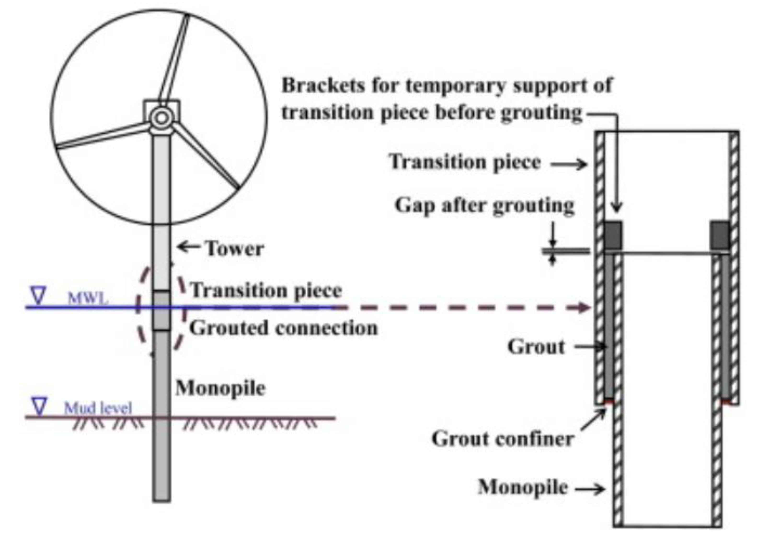
Figure 1. Traditional grouted connection (adapted from [7], with permission from Wiley-VCH Verlag GmbH & Co. KGaA. 2014.).
Metals 10 00732 g001
Figure 2. Revised design for grouted connection with shear keys (left) and cone design (right) (adapted from [9] with permission from DNV GL-Energy, 2016.
Metals 10 00732 g002
Figure 3. Wind turbine foundation types (adapted from [17] with permission from Elsevier, 2018): (a) onshore foundation, (b) gravity foundation, (c) monopile foundation, (d) Suction bucket foundation, (e) tripod foundation, (f) jacket foundation, (g) floating foundation.
Metals 10 00732 g003
Figure 4. (a) Components of a monopile foundation, and (b) schematic of a grouted connection (adapted from [7,9] with permission from DNV GL-Energy, 2016 (right). Copyright Wiley-VCH Verlag GmbH & Co. KGaA (left) 2014).
Metals 10 00732 g004
Figure 5. Capital expenditures for a fixed-bottom offshore reference wind plant project (adapted from [20], with permission from the National Renewable Energy Laboratory, https://www.nrel.gov/docs/fy18osti/70363.pdf, accessed 15 May 2020).
Metals 10 00732 g005
Figure 6. Schematic of common types of fasteners.
Metals 10 00732 g006
Figure 7. Schematic of a bolted flange connection.
Metals 10 00732 g007
Table 1. Offshore wind turbine foundation types and their characteristics.
Type of FoundationCharacteristics
Gravity foundation
(Figure 3b)
  • Self-weight supported and foundations made by reinforced concrete with ballast.
  • Total cost and seabed preparation are more demanding compared to monopile foundation, though the structure itself is cheaper.
  • Often used where piles cannot be easily driven.
  • Water depths of 0–30 m.
Monopile foundation
(Figure 3c)
  • 40%–50% of the length is inserted into the seabed.
  • Constructed onshore and demands small seabed preparation.
  • Water depths of 0–30 m.
Suction bucket foundation
(Figure 3d)
  • Upside-down bucket inserted into the seabed.
  • Fast installation and adaptable to larger water depths.
  • Idea originated from oil and gas industry as was initially used as an anchor for offshore floating oil and gas platforms.
  • Designed to withstand large horizontal loads, therefore studies in the technologies of installation and transportation to adapt it towards the needs of large vertical loads of an offshore wind turbine.
  • Water depths of 5–60 m.
Tripod foundation
(Figure 3e)
  • Expansion of the idea of the monopile foundation in order to adapt to deeper water depths.
  • Provides better stability and improves the stiffness of the entire structure.
  • Heavier foundation structure and harder to install, thus more costly than the monopile.
  • Water depths of up to 50 m.
Jacket foundation
(Figure 3f)
  • Another concept that came from the oil and gas industry.
  • Higher cost of installation and construction.
  • Mostly used as a transitional substructure.
  • Water depths of 10–60 m and some up to 80 m.
Floating foundation
(Figure 3g)
  • Address the issue of open seas and large water depths.
  • Consists of a floating platform and an anchor system connected to the seabed.
  • Main types are spar floater, tension leg platform, and semi-submersible foundation, which are systems already applied successfully to the oil and gas sector.
  • First offshore wind farm with a spar type floating foundation has been fully commissioned in the United Kingdom (“Hywind Scotland Pilot Park”).
  • Water depths of greater than 50 m.