Article

Experimental Characterization of Tool Wear Morphology and Cutting Force Profile in Dry and Wet Turning of Titanium Metal Matrix Composites (Ti-MMCs)

by
Masoomeh Safavi
1,
Marek Balazinski
2,
Hedayeh Mehmanparast
3 and
Seyed Ali Niknam
1,2,*
1
School of Mechanical Engineering, Iran University of Science and Technology, Tehran 13114-16846, Iran
2
Department of Mechanical Engineering, Polytechnique Montreal, Montréal, QC H3T 1J4, Canada
3
Gina Cody School of Engineering and Computer Science, Department of Mechanical, Industrial and Aerospace Engineering (MIAE), University of Concordia, Montréal, QC H3G 1M8, Canada
*
Author to whom correspondence should be addressed.
Metals 2020, 10(11), 1459; https://doi.org/10.3390/met10111459
Submission received: 6 October 2020 / Revised: 26 October 2020 / Accepted: 27 October 2020 / Published: 31 October 2020
(This article belongs to the Special Issue Microstructure, Deformation, and Fatigue Behavior in Metals)

Abstract

:
Metal-matrix composites (MMCs) are made of non-metallic reinforcements in metal matrixes, which have excellent hardness, corrosion, and wear resistance. They are also lightweight and may pose a higher strength-to-weight ratio as compared to commercial titanium alloys. One of the MMCs with remarkable mechanical properties are titanium metal matrix composites (Ti-MMCs), which are considered a replacement for super-alloys in many industrial products and industries. Limited machining and machinability studies of Ti-MMCs were reported under different cutting and lubrication conditions. Tool wear morphology and life are among the main machinability attributes with limited attention. Therefore, this study presents the effects of cutting and lubrication conditions on wear morphology in carbide inserts when turning Ti-MMCs. To that end, maximum flank wear (VB) and cutting forces were recorded, and the wear morphologies within the initial period of the cut, as well as the worn condition, were studied under dry and wet conditions. Experimental results denoted that despite the lubrication mode used, abrasion, diffusion, and adhesion mechanisms were the main wear modes observed. Moreover, built-up layer (BUL) and built-up edge (BUE) were the main phenomena observed that increase the tendency of adhesion at higher cutting times.

1. Introduction

Titanium metal matrix composites (Ti-MMCs) are known as a new generation of material that has many advantages over titanium alloys. Generally, it is recognized by reinforcements such as titanium carbide particles (TiC), titanium boride (TiB) and continuous or discontinuous silicon carbide fiber (SiC) [1,2]. Among them, reinforcement by hardest refractories, such as TiC particles, may provide excellent properties at high temperatures and with abrasion resistance. The abrasion increases proportionally according to the volume of reinforcements used in the MMC [3]. Due to high strength, low weight, and significant strength-to-weight ratio, as well as creep resistance at high temperature, Ti-MMCs are considered a desirable alternative to commercial superalloys (including Inconel and titanium alloys) in a wide range of applications, including aerospace and automotive industries [4,5,6,7,8,9]. However, due to the abrasive properties of hard reinforcement particles, machining a Ti-MMC is difficult and challenging [10,11]. Reinforced MMCs with ceramic particles have several advantages over their base metals, including unique strengths, higher wear resistance at high temperatures, and thermal stability coefficients. Consequently, low surface quality and limited tool life are expected in machining reinforced MMCs. The use of carbide and polycrystalline diamond (PCD) tools in machining MMCs have been observed in the open literature. Many other studies were also performed on turning, followed by horizontal milling and drilling operations [12].
Several studies [13,14,15] show that abrasion is the primary tool wear mechanism in machining MMCs. Abrasion is occurred due to complicated physical, chemical, and thermomechanical interactions because of the collision between the reinforcing particles and the cutting tool [16]. The rapid tool wear, which in general appears due to abrasion, is one of the undesirable phenomena in machining Ti-MMCs. Due to the very low thermal conductivity of Ti-MMCs, the high level of generated temperature in the cutting zone leads to the rapid abrasion of the cutting tool in a tiny area around the cutting edge [17]. The presence of abrasion has been investigated in almost all cutting conditions [8,18,19]. Oxidation and diffusion mechanisms also appear due to high-temperatures generated in the machining zone and rapid abrasion in cutting tools [20]. As noted in several studies [9], the permitted levels of maximum flank wear (VB) vary between 0.2 and 0.5 mm for different materials [1,5]. In the case of superalloys, it is advised not to use cutting tools with VB higher than 0.3 mm. The cutting time to reach the maximum permitted VB is the useful life of the cutting tool. Figure 1 shows the typical tool wear curve that is composed of three distinct regions due to increased tool wear with cutting time: (I) primary or initial wear (II) steady wear, and (III) accelerated wear, which was proposed by Taylor [21]. A longer time to reach maximum VB means better tool performance under similar cutting conditions [21,22].
Despite much research work in recent decades, factors governing initial tool wear and size have not yet been investigated in a wide scope [3]. Regardless of investigations made on machining and machinability evaluation of Ti-MMCs [17,23,24], few studies focused on the adequate cutting tools used in machining Ti-MMCs [25]. A review of the literature indicated that a Ti-MMC is classified as an extremely hard to cut material, and surprisingly limited studies were reported on machining Ti-MMCs under different machining and lubrication conditions. In principle, no meaningful information was available on initial tool wear, and factors governing tool life improvement when machining Ti-MMCs. Superficial knowledge on the relationship between the initial tool wear morphology, ultimate tool life, and cutting forces may lead to an inadequate selection of cutting parameters and decreased tool life. To remedy this lack of knowledge, the current study presents the effects of cutting and lubrication conditions on initial wear morphology, size, and cutting forces in the turning of Ti-MMCs. The wear modes, as well as the relationship between cutting forces and wear morphology, were investigated.

2. Materials and Methods

Turning was conducted on a cylindrical rod of Ti-MMC with a diameter of 119.6 mm and a length of 140 mm using two grades of coated carbide inserts, TS2500 and TS2000, with commercial codes CNMG 120404-MF1 and CNMG120404-MF4, respectively. According to recommendations by the SECO tools catalog, TS2000 and TS2500 are proposed grades for machining heat-resistant superalloys and titanium alloys. TS2000 is an ideal choice for finishing and semi-finishing of heat-resistant alloys, while TS2500 is recommended for roughing and semi-roughing of heat-resistant alloys. The MF1 is the proposed chip breaker for finishing and semi-finishing operations, and MF4 is proposed for semi-finishing to roughing operations of heat-resistant alloys.
The full specifications of the inserts used, as well as the chemical composition of the tested material, are presented in Table 1 and Table 2. An overview of the experimental set-up is presented in Figure 1. The fixed levels of cutting speed 70 m/min, feed rate 0.15 mm/rev as well as the depth of cut 0.5 mm were used. The experimental works were conducted in both dry and wet modes. The Bio-lubricant Mecagreen 550 was used as the lubricant in this work. Besides lubrication modes, another variable used in this work was cutting time, which varied within intervals from 0.5 to 8 s. Cutting parameters were selected according to recommendations made by the cutting tool manufacturer SECO Inc (Montreal, QC, Canada). The experimental works were repeated twice.
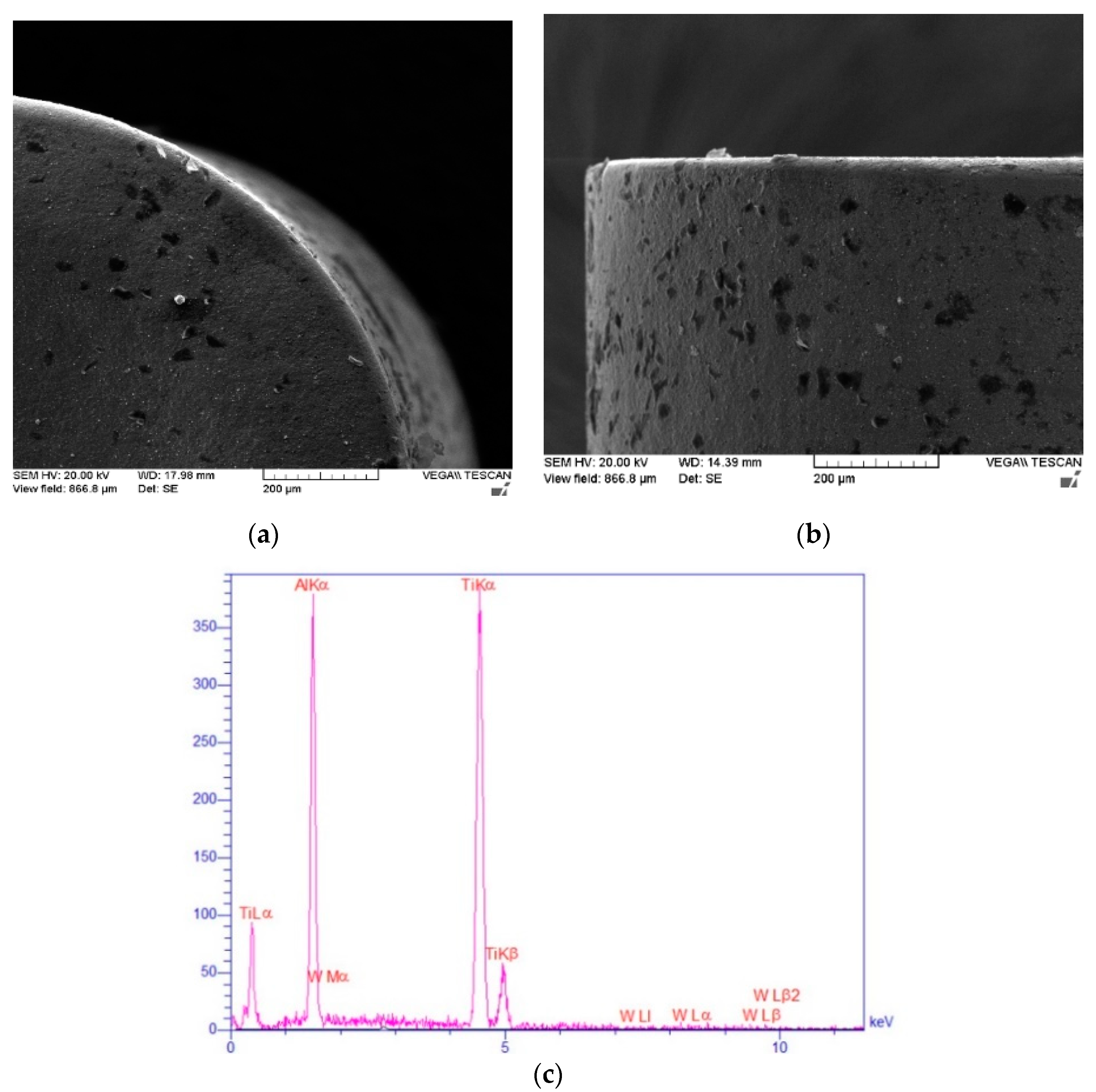
To evaluate the relationship between cutting force and tool wear rate, the cutting forces in different directions were recorded using a KISTLER turning table dynamometer (Winterthur, Switzerland) (Figure 2) with a sampling frequency of 12 kHz. To study insert wear mechanisms, two SEMs (JEOL, JSM-840A and JEOL JSM 7800F FEG-SEM, St-Hubert, Laval, QC, Canada) equipped with Oxford X-ray detection systems (AZtec EDX) for elemental analysis and quantitative mapping were used. Moreover, the JEOL JSM was a field emission SEM equipped with field emission guns (FEG), which provided a high resolution of 0.8 nm at 15 kV and 1.2 nm at 1 kV. Turning tests were repeated twice, and the average values were used. The tool wear measurements were conducted from the SEM images according to the ISO3685 standard. As noted earlier, the maximum flank wear (VB) was used as the tool wear attribute. To evaluate the tool wear morphology, the chemical composition of the tested materials was studied (Table 2). This allowed a better determination of the wear modes. For instance, the presence of material composition on the tool surface might be interpreted as the signature of adhesion. To detect chemical compositions of the insert surface as a result of generated wear modes, EDX was implemented with particular emphasis on those areas which seem to affect adhesion and abrasion modes. The SEM images of the rake side and flank side of the unused insert TS2500 and EDX of the flank side of the insert surface are presented in Figure 2 and Table 2, respectively. According to Figure 2 and Table 2, the main contributing elements on the insert surface are Al and Ti. The EDX image of the unused flank side of the insert (Figure 2c) comprised of over 99% Al and Ti. The X-axis of Figure 2c represents energy (keV), and the Y-axis is counts.

3. Results and Discussion

The experimental studies were conducted in dry and wet lubrication modes under similar cutting conditions and cutting tools.

3.1. Dry Mode

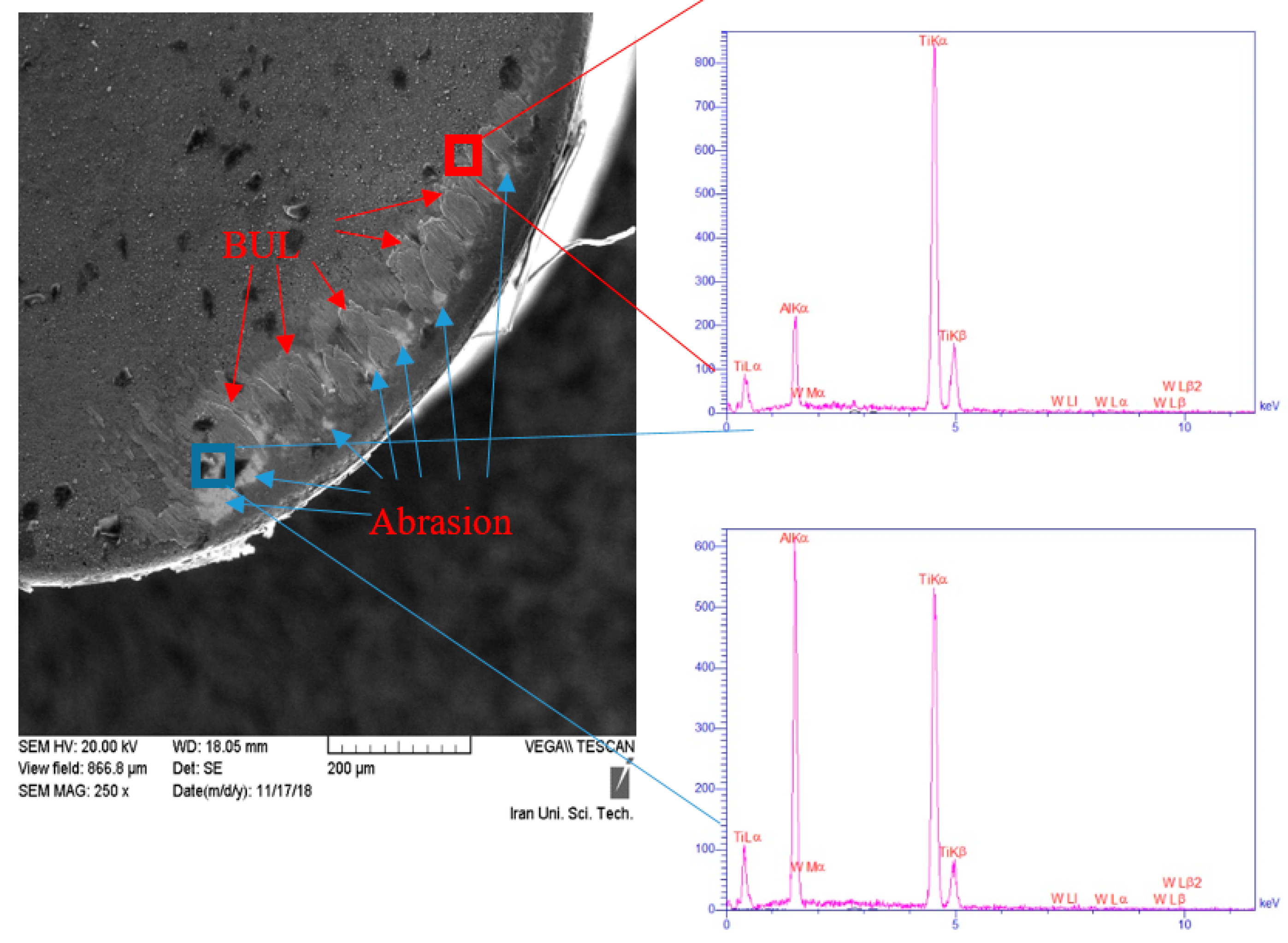
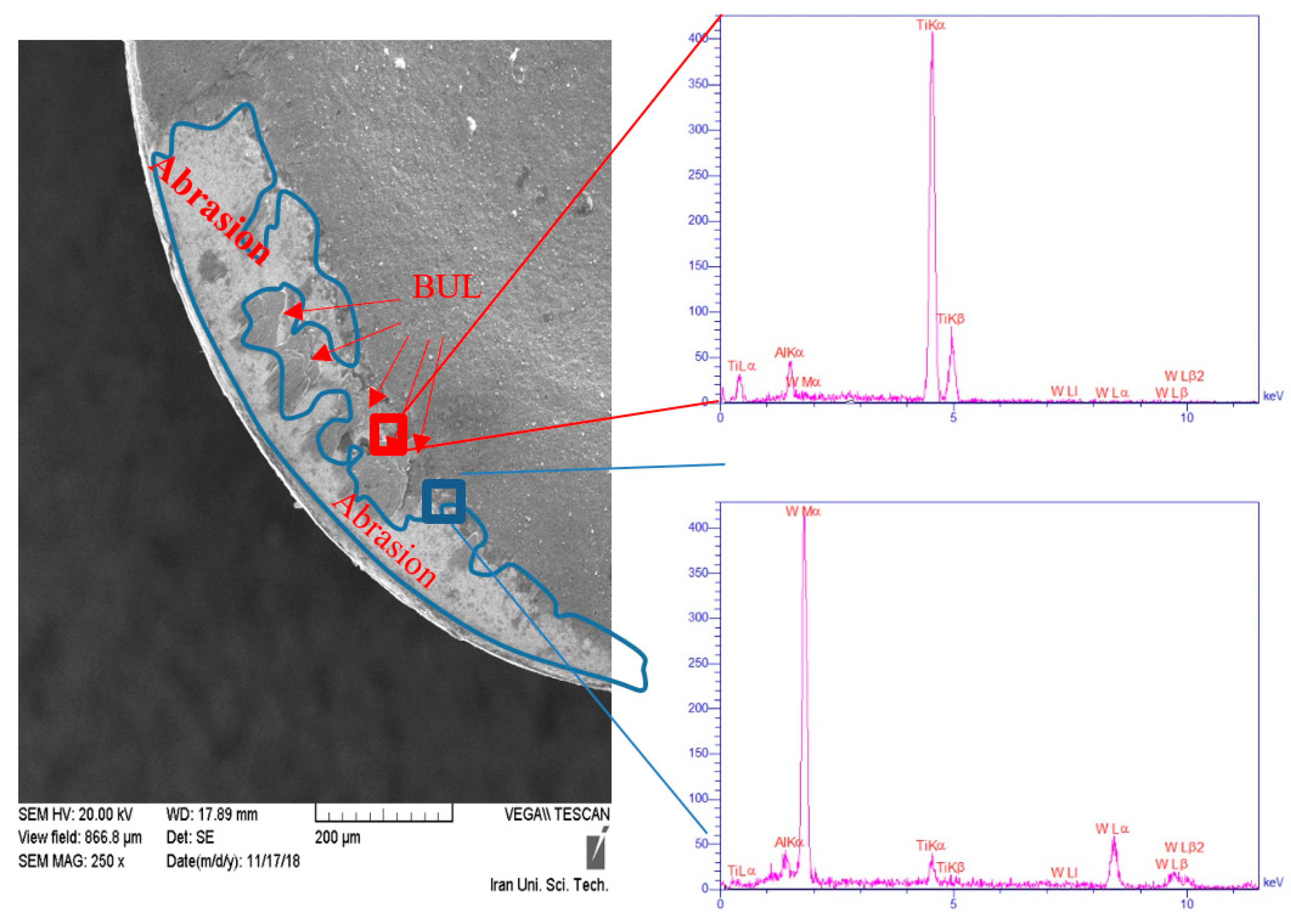
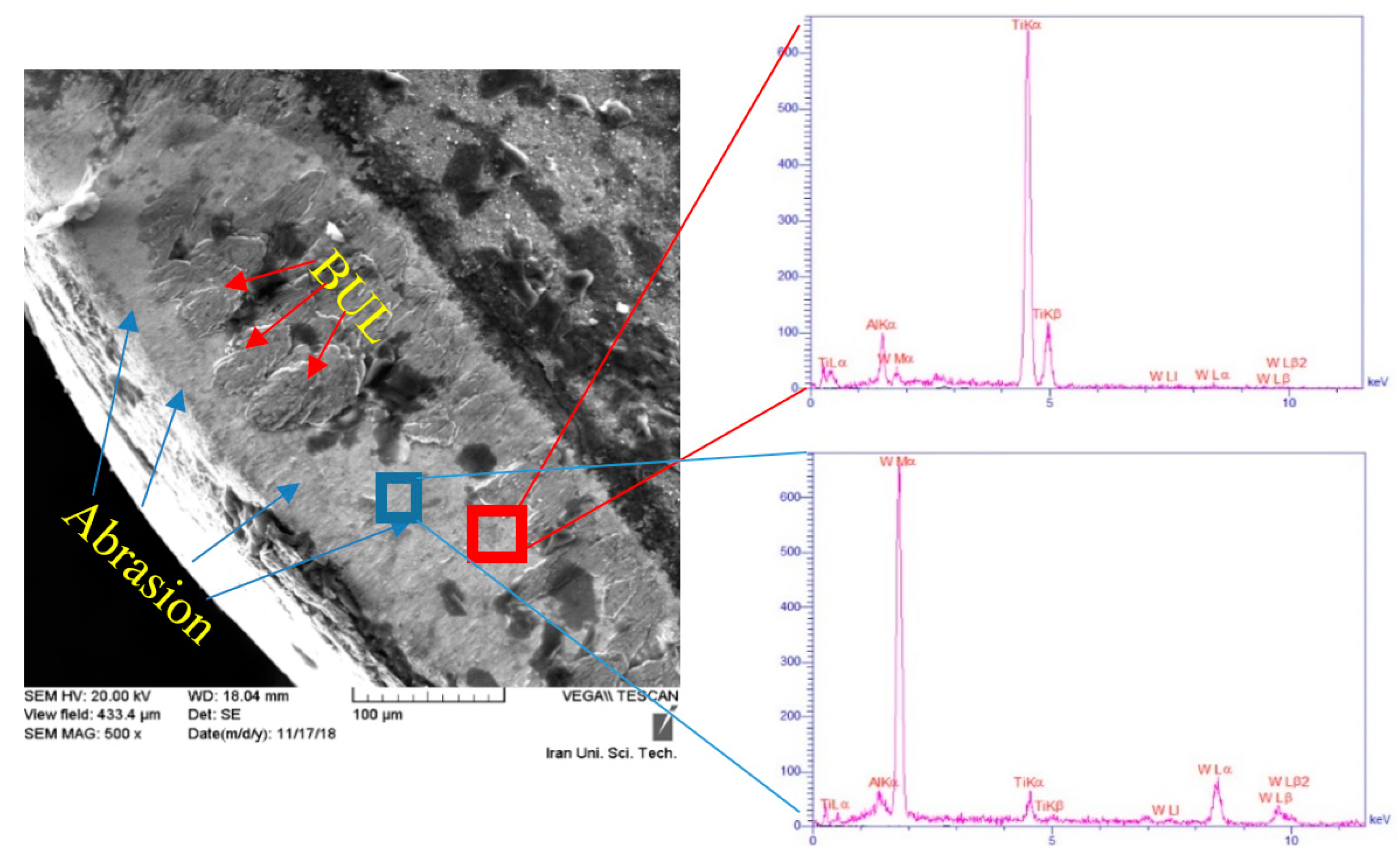
According to Figure 3 and Figure 4, after a short cutting time (e.g., 0.5 s), the matrix used in MMCs may tend to generate built-up layer (BUL) and built-up edge (BUE). Regardless of the experimental conditions used, abrasion was the main wear mechanism in machining Ti-MMCs [18,26]. This mechanism also depends on the nature and hardness of hard particles used in the metal composite [16]. Abrasion and BUL were two main wear phenomena in turning Ti-MMCs. El-Gallab and Sklad [27] indicated that BUE might cause chipping and instability of cutting operations. Figure 3 and Figure 4 show that BUL was the main wear mode in insert 1 (TS2000), while abrasion was the main wear mode in insert 2 (TS2500). The compositions wt.% of the worn areas on both inserts are shown in Table 3. Even at the low cutting time (0.5), the coating on some areas on the surface of insert TS2500 has been completely removed, and the W (tungsten), which is the core element of the insert has been observed. In other words, abrasion had occurred even at a very low cutting time when insert TS2500 was used.
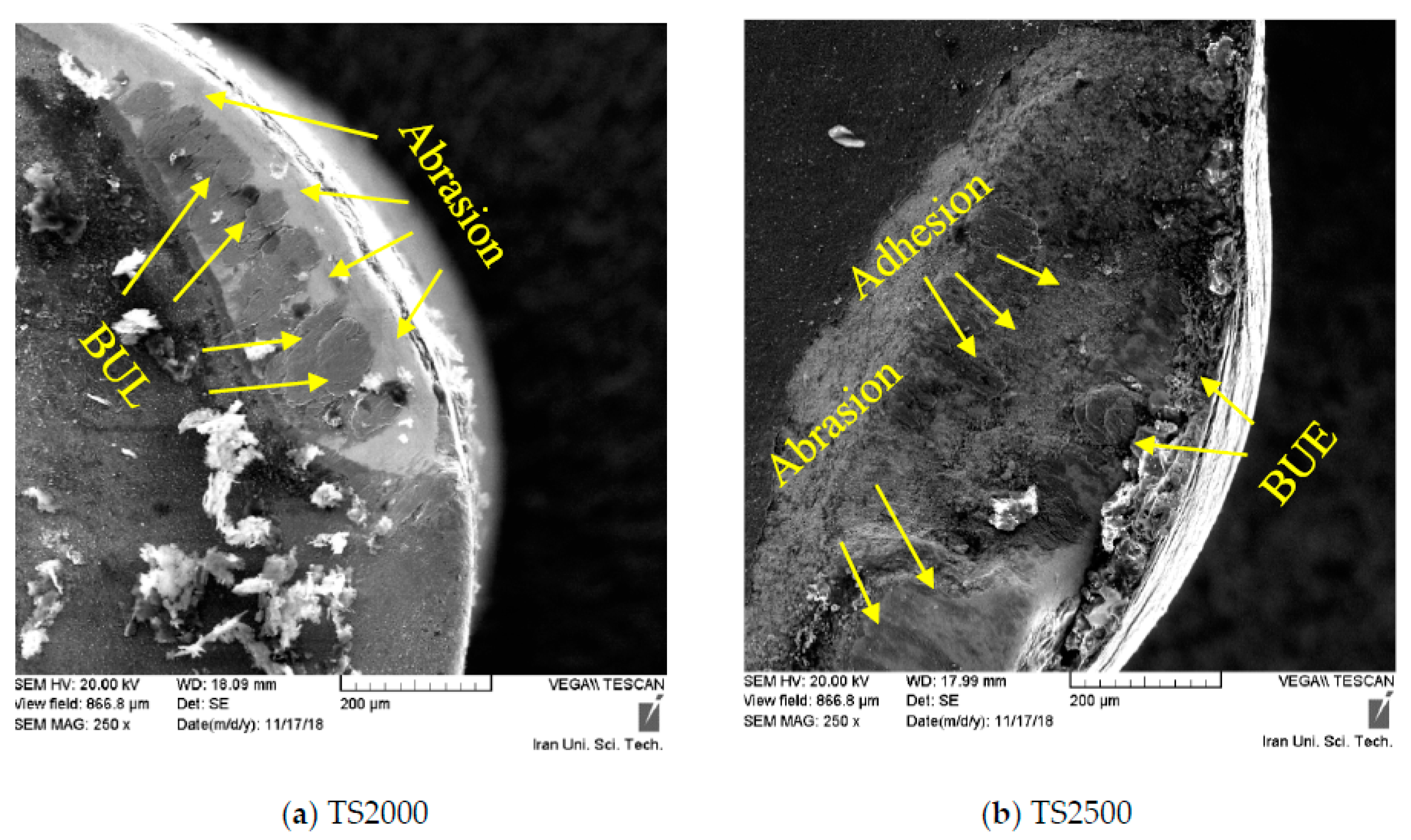
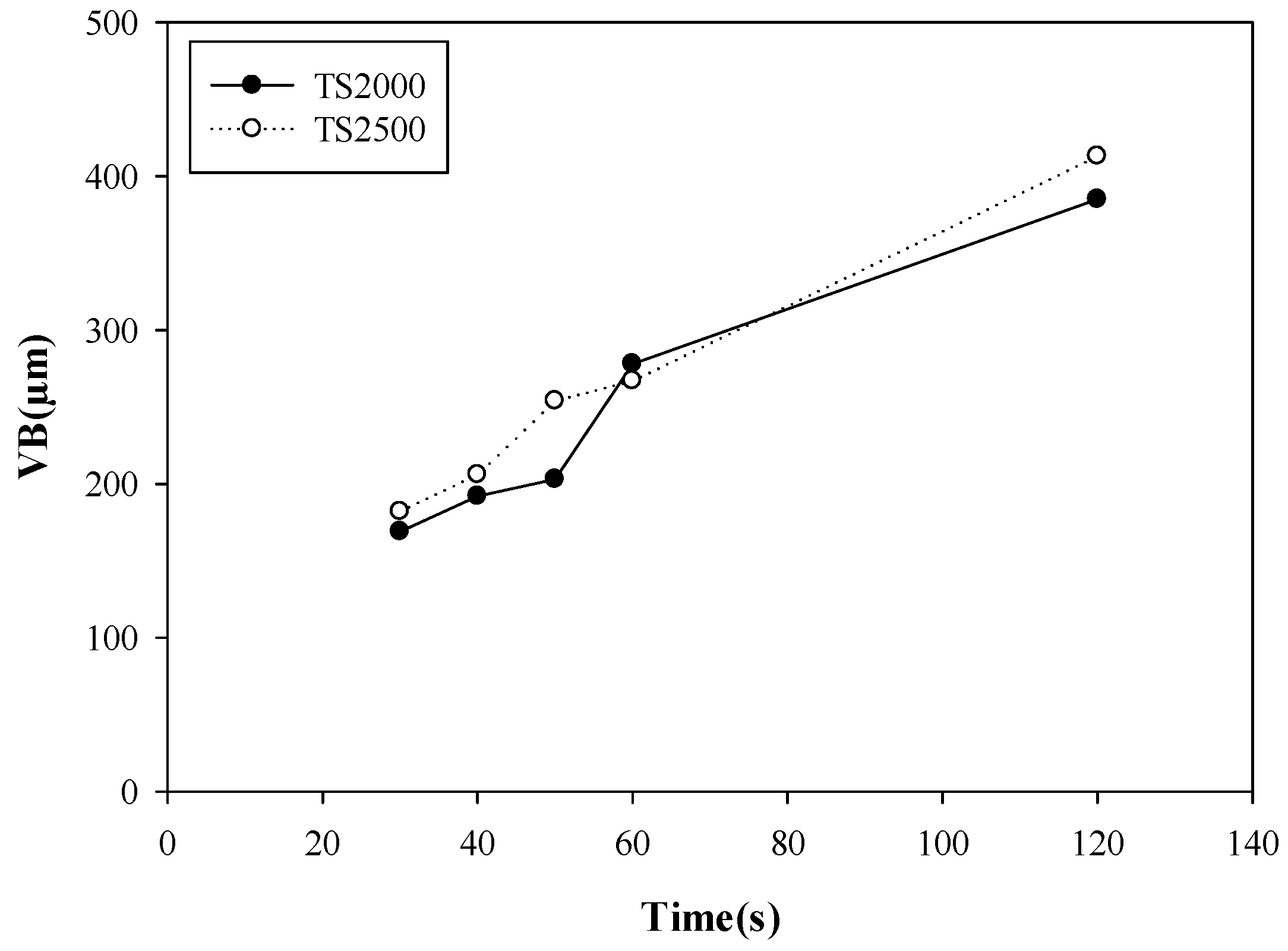
Micro-welds and BUE were formed at the cutting edge in all experimental conditions used (Figure 3, Figure 4 and Figure 5). In general, at the first moments of machining operations, the rake face of the cutting tool has an intense interaction with the workpiece. Due to generated thermo-mechanical stresses, the initial wear behavior may occur during very short periods. Therefore, the tribological friction and wear can be attributed to areas of two new surfaces, in which the slip speed between the two new surfaces at the small edge of the cutting in these regions is close to zero [28,29]. Hence, it seems that the flatness and cleanliness of the contact surface can be attributed to static friction [30]. Adhesive chips on the tool surface may act as a barrier against abrasion wear. However, at a longer cutting time, adhesive chips separated from the cutting tool surface (Figure 5), and eventually, larger BUE formed and consequently, rapid tool wear occurs [26]. Despite the cutting tool used, a gradual increase in flank wear (VB) with high impacts on initial wear was noticed in machining Ti-MMCs (Figure 6). According to Figure 5 and Figure 6, after 60 s of turning operation, insert 2 (TS2000) had reached the maximum allowable flank wear limit (300 microns). EDX results showed that areas with abrasion, tungsten was higher than other elements because the coating layer had been removed by abrasion. After longer cutting times, more VB was seen on both inserts (Figure 5 and Figure 6). The wider regions were attributed to abrasion, which can be related to the effects of reinforcing particles TiC, which are abrasive [8,31]. The scratches and grooves are seen and would prove the abrasion wear mechanism due to the hard and abrasive TiC particles in the workpiece material, which led to the complete removal of the coating. The effects of abrasive particles on temperature generation, tool wear morphology as well as friction need to be understood in a broader scope. However, these topics are not within the current scope of this study.
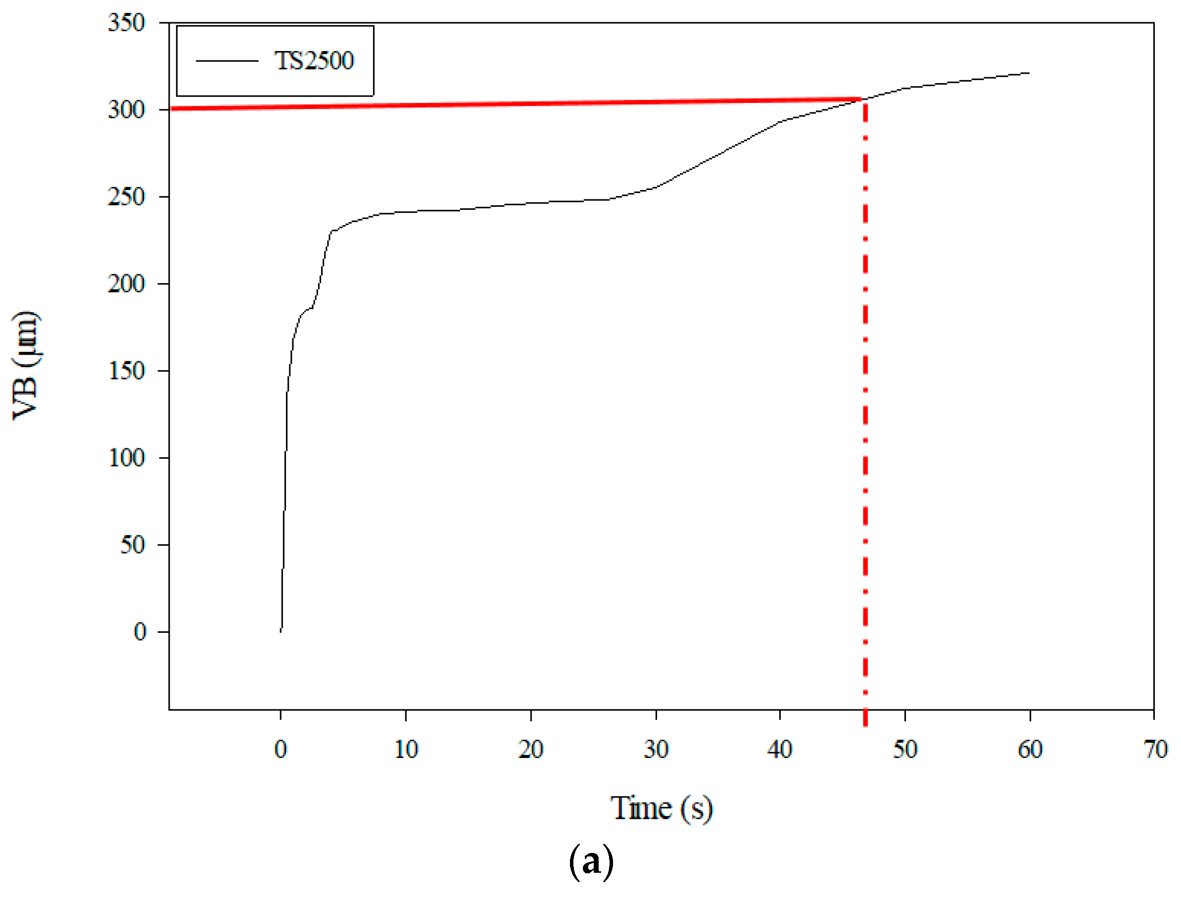
Since TiC is ceramic and can be even used as a coating, as a result of direct contact with the coating layer, coating removal, and scratches on the insert surface may occur. At longer cutting times, the thickness of BUL increased. These areas occurred irregularly as a result of adhesion. High tool wear, which occurred in the first few seconds of machining, was attributed to the initial impact of the cutting tool with the work part elements. Therefore, at the second stage of the tool wear curve, the stable trend of flank wear was observed. As depicted in Figure 2, the third wear zone, or accelerated zone, appeared at the higher cutting time and the specific cutting time where the maximum flank wear VB can be achieved at the third wear zone. Higher permitted cutting time means longer tool life at the specific cutting speed used. According to Figure 6, the maximum permitted VB (0.3 mm) for insert TS2500 was achieved in less than 60 s, which is very quick.
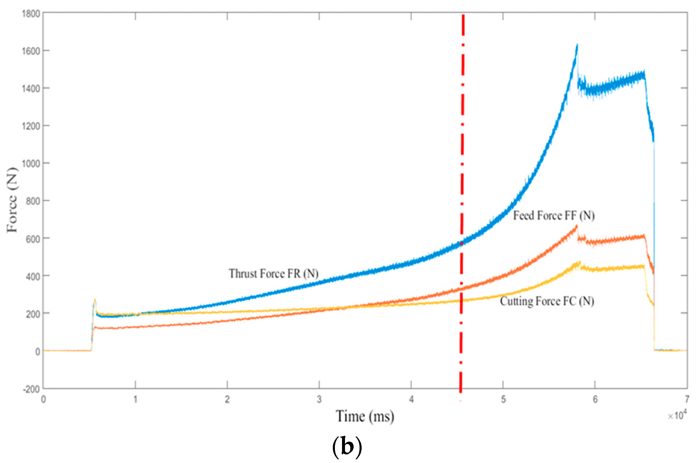
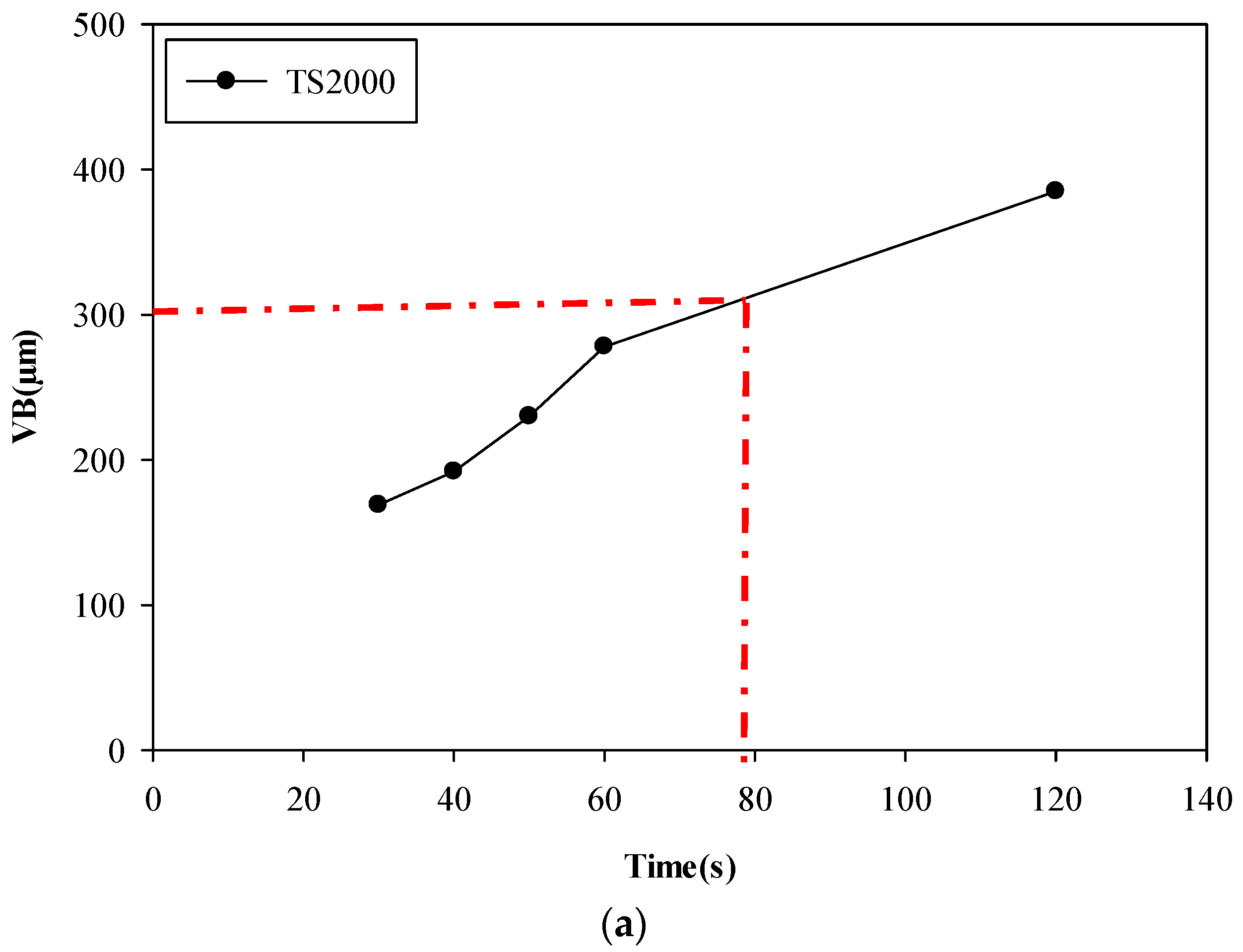
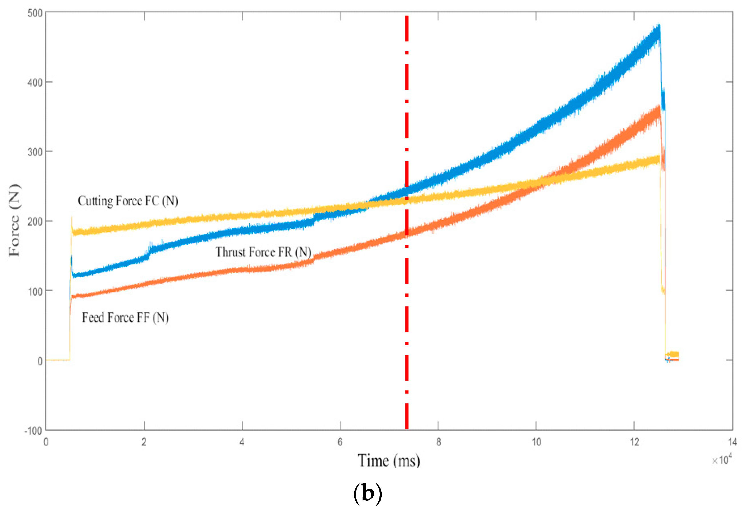
Duong et al. [32] reported that the initial cutting conditions could significantly affect the entire tool life and tool wear mechanisms. To interpret the correlation between the cutting forces and tool wear morphology and tool wear size, the cutting forces in all three directions were measured. The turning cutting forces can be expressed as thrust force, feed force, and cutting force. The overview of cutting force at 60 s, followed by the tool wear curve for each insert, is presented in Figure 7 and Figure 8. According to Figure 7a, the maximum permitted tool life was reached after almost 45 s. As shown in Figure 7b, a rapid increase in cutting force in all three directions was attributed to elevated tool wear and removal of the cutting edge and BUE on the cutting tool (Figure 5b), which increased the contacting surface between the cutting tool and workpiece, and eventually, more chip removal and higher cutting forces occurred (Figure 7b). Therefore, the cutting force sharply increased when VB exceeded 300 microns. According to Figure 8, although maximum allowable VB was not reached after 60 s, a gradual increase in cutting force after 45 s of cutting may tend to elevate the flank wear. As shown in Figure 6, Figure 7b and Figure 8b, increased VB occurred in the first few seconds on cutting tests. Adequate selection of cutting parameters to decrease the VB in the initial wear zone could prolong the tool life.
Figure 7b and Figure 8b reveal that under constant cutting parameters, the thrust force and feed force tend to increase when cutting time increases. In other words, although the cutting time does not vary significantly, the cutting forces increase at initial moments of cutting. Furthermore, when the permitted VB was reached, the cutting force tended to change. This can be attributed to the intense effects of the worn insert on the cutting force profile. When the insert edge is worn, the contacting surface between the workpiece and the edge increases. Consequently, thicker chips removal and higher resulting values of cutting forces may occur. Despite the uniform cutting conditions used, the increased cutting forces at the higher cutting time were observed. Referring to the Taylor tool life model, the second tool wear region, the steady zone, happens very quickly, and in fact, the third region is known as the “accelerated wear zone”, which starts very soon. The rapidly increased cutting force and tool wear in both inserts was observed.

3.2. Wet Mode

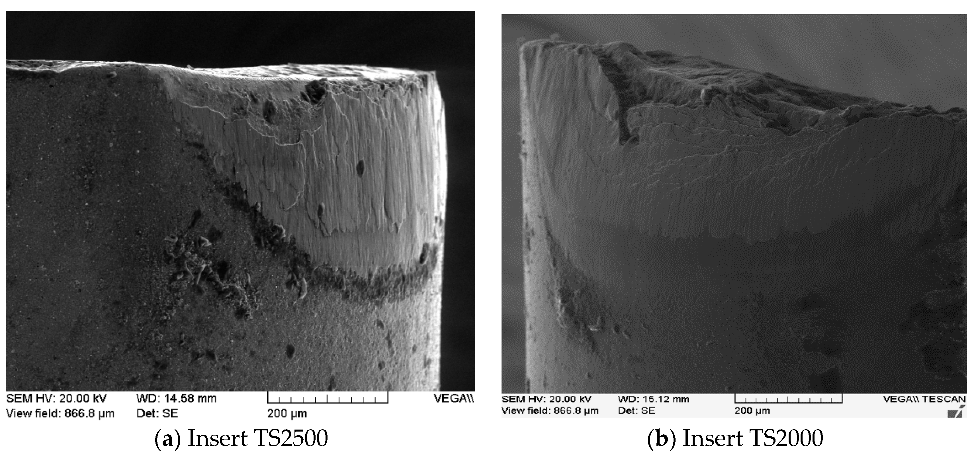
The cutting tests were performed at 30, 40, 50, 60 and 120 s under wet mode. The wear modes on the rake face in wet machining must be studied in machinability evaluation of high-resistance alloys [9]. Figure 9, Figure 10 and Figure 11 illustrate the wear morphology on the flank face and the rake face of both inserts TS2000 and TS2500 after 120 s of cutting operation. The flank sides of both inserts were worn and could not be allowed for additional tests after 120 s cutting, although the rake side wear seems to be less than 0.3 mm. According to Figure 12, Figure 13 and Figure 14, flank wear (VB) sharply rose when cutting time increased, and the maximum allowable flank wear (VB) was achieved for both inserts at around 70 s. Abrasion and BUL were the main wear modes. The slopes of wear profiles in Figure 12, Figure 13 and Figure 14 indicate that similar to the dry mode, the wet machining of the Ti-MMC was associated with a very short steady wear zone and elevated wear at short cutting times. The use of wet machining had negligible improvement on the useful life of both inserts compared to the dry mode. In general, it can be stated that regardless of the cutting insert and lubrication mode used, machining Ti-MMCs is associated with limited tool life.
Similar to dry turning, the overview of cutting forces in Figure 12 and Figure 13 showed that under constant cutting parameters, the thrust force and feed force tended to increase when cutting time increased. When the permitted level of flank wear (VB) was reached, the cutting forces had increased almost three times. In other words, although the cutting time did not vary significantly, the cutting forces increased sharply. The rapid increase in cutting force and tool wear in both inserts can be observed and can be attributed to elevated tool wear. As noted earlier in [4], when the cutting tool wears and loses its sharpness, more considerable interaction occurs between the cutting tool and the workpiece, and consequently, larger chip thickness is caused as a result of the worn tool. It is known that turning cutting forces are directly affected by the chip thickness and the cutting tool geometry [33]. Higher chip thickness tends to increase the cutting force, and as a result of increased cutting forces, elevated cutting temperatures may occur [33]. The flank wear (VB) of both inserts at various cutting times under wet mode were measured from SEM images and presented in Figure 14.

4. Conclusions

According to a review of the literature, limited studies are available on machining of Ti-MMCs with commercial cutting tools under various cutting conditions and cutting tools/inserts. Furthermore, limited studies were found on the machinability evaluation of Ti-MMCs under various cutting conditions. Therefore, to remedy the lack of knowledge observed, this study intended to study the effects of cutting parameters on the machinability attributes of Ti-MMCs when using carbide tools. According to experimental results, the following conclusion can be drawn:
  • High flank wear occurred in the first few seconds of machining a Ti-MMC under both dry and wet modes.
  • Abrasive particles could be understood as the essential problem observed under high-speed machining of Ti-MMCs. The matrix behavior and hydrostatic pressure of the cutting edge play prominent roles at low levels of cutting speeds. In this case, the cutting tool acquires sufficient hardness to prevent abrasion and resists the deflection forces.
  • Despite the wet cutting mode used, abrasion and BUL was the main wear mode in both inserts. This was attributed to ceramic and SiC particles that are abrasive and hard and consequently may accelerate the coating removal process right after the cutting process. Moreover, the tendency for BUL and BUE was intensified at higher levels of cutting time.
  • Regardless of the cutting insert and lubrication mode used, machining Ti-MMCs was associated with limited tool life, although better life was observed under wet mode.
  • Other major problems that may tend to hinder the machinability of Ti-MMCs is elevated temperature in the cutting zone, which was shown as sparks and burnt chips in the cutting operations. Thus, the tool/insert should resist the high abrasion and thermal loads (i.e., CBN). In addition, further studies with respect to the presence of chatter vibration in dry and wet machining of Ti-MMCs with carbide tools and other commercial tools are of prime importance in prospective studies.

Author Contributions

The research results in this work were presented in the B.Sc. project of M.S. The work was initiated from a research project on Machining Ti-MMC, which has been initiated between M.B. and S.A.N., faculty members of Iran University of Science and Technology, and Polytechnique Montreal. The project was supervised by S.A.N. H.M. also contributed to experimental characterizations, signal processing, and article preparation. All authors have read and agreed to the published version of the manuscript.

Funding

This research was funded by Fonds de Recherche du Québec–Nature et technologies (FQRNT).

Conflicts of Interest

The authors declare no conflict of interest. The funders had no role in the design of the study; in the collection, analyses, or interpretation of data; in the writing of the manuscript, or in the decision to publish the results.

References

  1. Bejjani, R. Machinability and Modeling of Cutting Mechanism for Titanium Metal Matrix Composites; École Polytechnique de Montréal: Montréal, QC, Canada, 2012. [Google Scholar]
  2. Bejjani, R.; Balazinski, M.; Attia, H.; Plamondon, P.; L’Éspérance, G.; Plamondon, P. Chip formation and microstructure evolution in the adiabatic shear band when machining titanium metal matrix composites. Int. J. Mach. Tools Manuf. 2016, 109, 137–146. [Google Scholar] [CrossRef]
  3. Duong, X.; Mayer, J.; Balazinski, M. Initial tool wear behavior during machining of titanium metal matrix composite (TiMMCs). Int. J. Refract. Met. Hard Mater. 2016, 60, 169–176. [Google Scholar] [CrossRef]
  4. Niknam, S.A.; Kouam, J.; Songmene, V.; Balazinski, M. Dry and semi-dry turning of Titanium Metal Matrix Composites (Ti-MMCs). Procedia CIRP 2018, 77, 62–65. [Google Scholar] [CrossRef]
  5. Bejjani, R.; Balazinski, M.; Shi, B.; Attia, H.; Kishawy, H. Machinability and chip formation of titanium metal matrix composites. Int. J. Adv. Manuf. Syst. IJAMS 2011, 13, 75–90. [Google Scholar]
  6. Kim, J.-S.; Lee, K.-M.; Cho, D.-H.; Lee, Y.-Z. Fretting wear characteristics of titanium matrix composites reinforced by titanium boride and titanium carbide particulates. Wear 2013, 301, 562–568. [Google Scholar] [CrossRef]
  7. Kim, T.-W. Microstructural aspects of titanium metal matrix composites in consolidation processing. Mater. Lett. 2005, 59, 143–147. [Google Scholar] [CrossRef]
  8. Bejjani, R.; Shi, B.; Attia, H.; Balazinski, M. Laser assisted turning of Titanium Metal Matrix Composite. CIRP Ann. 2011, 60, 61–64. [Google Scholar] [CrossRef]
  9. Niknam, S.A.; Khettabi, R.; Songmene, V. Machinability and machining of titanium alloys: A review. In Machining of Titanium Alloys; Springer: Berlin/Heidelberg, Germany, 2014; pp. 1–30. [Google Scholar]
  10. Rajmohan, T.; Palanikumar, K. Application of the central composite design in optimization of machining parameters in drilling hybrid metal matrix composites. Measurement 2013, 46, 1470–1481. [Google Scholar] [CrossRef]
  11. Rajmohan, T.; Palanikumar, K.; Prakash, S. Grey-fuzzy algorithm to optimise machining parameters in drilling of hybrid metal matrix composites. Compos. Part B Eng. 2013, 50, 297–308. [Google Scholar] [CrossRef]
  12. Nicholls, C.J.; Boswell, B.; Davies, I.J.; Islam, M.N. Review of machining metal matrix composites. Int. J. Adv. Manuf. Technol. 2016, 90, 2429–2441. [Google Scholar] [CrossRef]
  13. Altintas, Y. Prediction of cutting forces and tool breakage in milling from feed drive current measurements. J. Eng. Ind. 1992, 114, 386–392. [Google Scholar] [CrossRef]
  14. Hocheng, H.; Yen, S.; Ishihara, T.; Yen, B. Fundamental turning characteristics of a tribology-favored graphite/aluminum alloy composite material. Compos. Part A: Appl. Sci. Manuf. 1997, 28, 883–890. [Google Scholar] [CrossRef]
  15. Yanming, Q.; Zehua, Z. Tool wear and its mechanism for cutting SiC particle-reinforced aluminium matrix composites. J. Mater. Process. Technol. 2000, 100, 194–199. [Google Scholar] [CrossRef]
  16. Li, X.; Seah, W. Tool wear acceleration in relation to workpiece reinforcement percentage in cutting of metal matrix composites. Wear 2001, 247, 161–171. [Google Scholar] [CrossRef]
  17. Asgari, A. Cutting Conditions Optimisation of Titanium Metal Matrix Composites in Turning and Face Milling; École Polytechnique de Montréal: Montréal, QC, Canada, 2015. [Google Scholar]
  18. Kishawy, H.; Kannan, S.; Balazinski, M. Analytical modeling of tool wear progression during turning particulate reinforced metal matrix composites. CIRP Ann. 2005, 54, 55–58. [Google Scholar] [CrossRef]
  19. Niknam, S.A.; Kamalizadeh, S.; Asgari, A.; Balazinski, M. Turning titanium metal matrix composites (Ti-MMCs) with carbide and CBN inserts. Int. J. Adv. Manuf. Technol. 2018, 97, 253–265. [Google Scholar] [CrossRef]
  20. Zhu, D.; Zhang, X.; Ding, H. Tool wear characteristics in machining of nickel-based superalloys. Int. J. Mach. Tools Manuf. 2013, 64, 60–77. [Google Scholar] [CrossRef]
  21. Taylor, F. On the art of cutting tools. Trans. ASME 1907, 28, 31–35. [Google Scholar]
  22. Viktor, P. Chapter 4 Cutting tool wear, tool life and cutting tool physical resource. Tribol. Interface Eng. Ser. 2006, 52, 220–275. [Google Scholar]
  23. Aramesh, M.; Shaban, Y.; Balazinski, M.; Attia, H.; Kishawy, H.; Yacout, S. Survival life analysis of the cutting tools during turning Titanium Metal Matrix Composites (Ti-MMCs). Procedia CIRP 2014, 14, 605–609. [Google Scholar] [CrossRef]
  24. Aramesh, M.; Attia, H.; Kishawy, H.A.; Balazinski, M. Observation of a unique wear morphology of cBN inserts during machining of titanium metal matrix composites (Ti-MMCs); leading to new insights into their machinability. Int. J. Adv. Manuf. Technol. 2017, 92, 519–530. [Google Scholar] [CrossRef]
  25. Kamali Zadeh, S. Initial Tool Wear Mechanisms in Turning of Titanium Metal Matrix Composites; École Polytechnique de Montréal: Montréal, QC, Canada, 2016. [Google Scholar]
  26. Joshi, S. Machining metal matrix composites using diamond tools. In Machining Technology for Composite Materials; Elsevier: Amsterdam, The Netherlands, 2012; pp. 426–459. [Google Scholar]
  27. Elgallab, M.S.; Sklad, M.P. Machining of Al/SiC particulate metal-matrix composites: Part I: Tool performance. J. Mater. Process. Technol. 1998, 83, 151–158. [Google Scholar] [CrossRef]
  28. Beste, U.; Jacobson, S. A new view of the deterioration and wear of WC/Co cemented carbide rock drill buttons. Wear 2008, 264, 1129–1141. [Google Scholar] [CrossRef]
  29. Ben Abdelali, H.; Courbon, C.; Rech, J.; Ben Salem, W.; Dogui, A.; Kapsa, P. Identification of a friction model at the tool-chip-workpiece interface in dry machining of a AISI 1045 steel with a TiN coated carbide tool. J. Tribol. 2011, 133, 042201. [Google Scholar] [CrossRef]
  30. Kagnaya, T.; Boher, C.; Lambert, L.; Lazard, M.; Cutard, T. Microstructural analysis of wear micromechanisms of WC–6Co cutting tools during high speed dry machining. Int. J. Refract. Met. Hard Mater. 2014, 42, 151–162. [Google Scholar] [CrossRef] [Green Version]
  31. Weinert, K.; König, W. A consideration of tool wear mechanism when machining Metal Matrix Composites (MMC). CIRP Ann. 1993, 42, 95–98. [Google Scholar] [CrossRef]
  32. Duong, X.-T.; Balazinski, M.; Mayer, R. Chaotic tool wear during machining of Titanium Metal Matrix Composite (TiMMCs). In Proceedings of ASME 2014 International Mechanical Engineering Congress and Exposition, Montreal, QC, Canada, 14–20 November 2014. [Google Scholar]
  33. Altintas, Y. Manufacturing Automation; Cambridge University Press: Cambridge, UK, 2000. [Google Scholar]
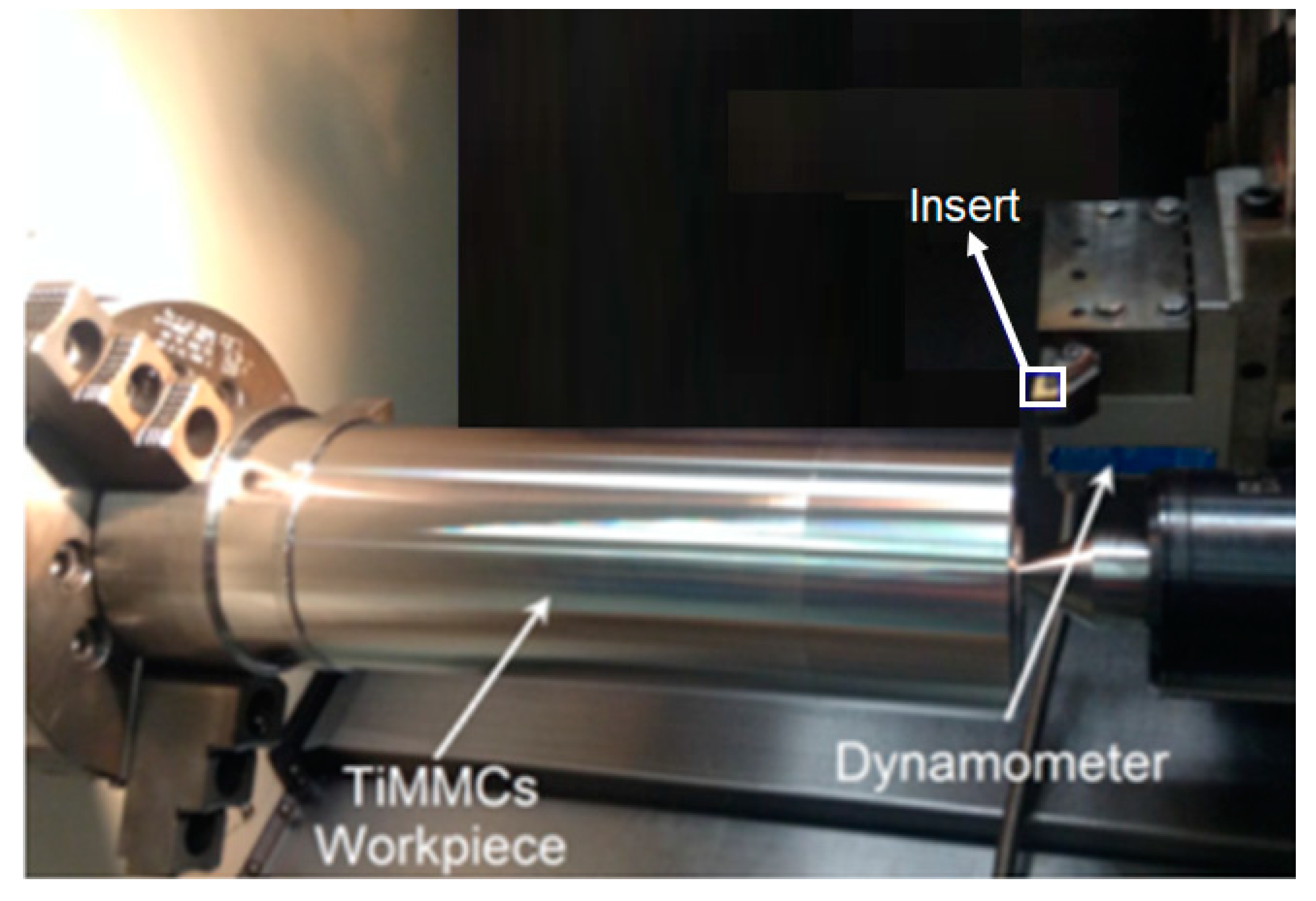
Figure 1. Experimental set-up used.
Metals 10 01459 g001
Figure 2. SEM images of the: (a) rake side; (b) flank side; (c) EDX analysis of the flank side of unused insert TS2500 (wt.%). Contribution of elemental compositions wt.% of the flank side with largest contributions of Al = 22.4% and Ti = 77.5%
Metals 10 01459 g002
Figure 3. SEM and EDX images for insert 1 (TS2000) after 0.5 s of cutting.
Metals 10 01459 g003
Figure 4. SEM and EDX images for insert 1 (TS2500) after 0.5 s of cutting.
Metals 10 01459 g004
Figure 5. Wear modes in both inserts after 60 s of cutting.
Metals 10 01459 g005
Figure 6. Flank wear (VB) profile for both inserts.
Metals 10 01459 g006
Figure 7. (a) Flank wear (VB); (b) cutting forces profile of insert TS2500 in 60 s of cutting.
Metals 10 01459 g007aMetals 10 01459 g007b
Figure 8. (a) Flank wear (VB); (b) cutting forces profile of insert TS2000 in 60 s of cutting.
Metals 10 01459 g008
Figure 9. Wear modes on the rake face of insert TS2000 after 120 s of cutting.
Metals 10 01459 g009
Figure 10. The SEM images of wear modes on the rake face of insert TS2500 after 120 s of cutting.
Metals 10 01459 g010
Figure 11. The SEM images of flank wear on both inserts after 120 s cutting. (a) Insert TS2500. (b) Insert TS2000.
Metals 10 01459 g011
Figure 12. (a) Flank wear (VB); (b) cutting force profile of insert TS2000 for 120 s of cutting time.
Metals 10 01459 g012aMetals 10 01459 g012b
Figure 13. (a) Flank wear (VB); (b) cutting force profile of insert TS2500 for 120 s of cutting time.
Metals 10 01459 g013
Figure 14. Flank wear (VB) under wet mode in both inserts.
Metals 10 01459 g014
Table 1. The specifications of the inserts used.
Insert CodeGradeCoating
CNMG 120404-MF1TS2000PVD TiSiN-TiAlN coated carbide with W as the core element and Co and Cr as binders
CNMG120404-MF4TS2500PVD TiSiN-TiAlN coated carbide with W as the core element and Co and Cr as binders
Table 2. Elemental composition of titanium metal matrix composites (Ti-MMCs) (wt.%).
Chemical Analysis of Ti-MMCAlVC OFeNHTi
Mass%5.53.80.90.20.0040.2<0.003Remainder (89.2)
Table 3. The elemental compositions (wt.%) on the worn areas presented in both inserts in Figure 4 and Figure 5.
Elements/Insert Insert TS2000Insert TS2500
AbrasionBULAbrasionBUL
Al (wt.%)48.7 23.8 6.319.9
Ti (wt.%)49.373.9 3.877.9
W (wt.%)2.32.489.92.2
Publisher’s Note: MDPI stays neutral with regard to jurisdictional claims in published maps and institutional affiliations.