Article

Study on Failure Mechanism and Phase Transformation of 304 Stainless Steel during Erosion Wear

1
Special Equipment Safety Supervision Inspection Institute of Jiangsu Province, Nanjing 210036, China
2
School of Mechanical Engineering, Changzhou University, Changzhou 213164, China
*
Authors to whom correspondence should be addressed.
Metals 2020, 10(11), 1427; https://doi.org/10.3390/met10111427
Submission received: 2 September 2020 / Revised: 19 October 2020 / Accepted: 23 October 2020 / Published: 27 October 2020
(This article belongs to the Special Issue Advances in Stainless Steel)

Abstract

:
In this paper, the failure mechanism and phase transformation process of 304 stainless steel during the erosion wear process were studied with a rotary erosion wear test device. The surface morphologies of the worn 304 stainless steel were investigated by scanning electron microscopy (SEM). The metallographic structures of the nonworn and worn 304 stainless steel were analyzed by optical microscope (OM) and transmission electron microscopy (TEM). In addition, the surface hardness on different areas of the sample was also measured. The results demonstrated that the failure mechanism of 304 stainless steel during the process of erosion wear was cutting and spalling caused by plastic deformation. The high-density dislocations move along the slip planes between slip lines, which resulted in the formation of martensite phase between the slip lines. Meanwhile, the martensitic transformation on the worn surface caused by severe plastic deformation was the coordination of dislocation martensite and twin martensite.

1. Introduction

Due to its excellent mechanical properties such as corrosion resistance, heat resistance and low-temperature strength, 304 stainless steel has been widely used in aerospace, ship and marine engineering, chemical and other fields [1,2]. It is commonly used in the equipment manufacturing of deoiling, dehalogenation, dehydration and so on [3]. However, due to the adverse effects of high-speed particles in the multiphase flow, the 304 stainless steel structures are extremely vulnerable to erosion wear. Erosion wear will gradually cause the changes in the size or shape of the components, causing the failure of the functions specified in the original design, which ultimately leads to the failure of equipment and reduces the service life [4]. It is of great significance to study the failure process of erosion wear on 304 stainless steel for revealing the failure mechanism, proposing the improvement measures and improving the enterprise efficiency.
Erosion wear is a kind of wear phenomenon that the material surface is damaged when it is impacted by small and loose flowing particles [5,6,7]. In industrial production, erosion wear failure of 304 stainless steel has brought serious economic losses. The economic loss caused by wear has reached 58.47 billion yuan per year in China while the value has reached 15 billion dollars per year in America, and erosive wear accounts for about 8% of the total wear in industrial production. Therefore, the research on the erosion wear of metal materials is becoming more and more active [8,9]. Huttunen-Saarivirta et al. studied the erosion wear mechanism of 304 L stainless steel in the condition with sand and ash [10]. Their results showed that the loss of 304 L stainless steel was mainly caused by ploughing deformation at the angle of 30° and impact craters at the angle of 90°. Jashanpreet Singha et al. studied the erosion wear mechanism of SS 304 stainless steel in the condition with coal-water slurry, and found that the main failure mechanism of SS 304 stainless steel was microcutting and microploughing [11]. Vikash Gautama et al. also pointed out that the erosion mechanism of brass under different operating conditions was microcutting and microploughing [12]. Furthermore, Wang et al. summarized the phase transformation and wear mechanisms of single-step and dual-step austempered ductile irons, and they pointed out that during the wear process, the worn surface of austempered ductile iron will induce martensite due to stress [13]. However, few studies have focused on the microstructure transformation of 304 stainless steel during the erosion wear process. Therefore, it is necessary to study the erosion wear failure process and microstructural transformation of 304 stainless steel.
In order to explore the failure process of 304 stainless steel, the erosion wear experiment of 304 stainless steel was conducted using a rotary erosion wear test device. The surface morphologies of the worn 304 stainless steel were observed by SEM, the metallographic structures of the nonworn and worn 304 stainless steel were studied by OM, and the microstructure of the worn 304 stainless steel was also observed by TEM. Finally, the failure mechanism and microstructure transformation mechanism of 304 stainless steel during erosion wear were also revealed.

2. Experiment Procedures

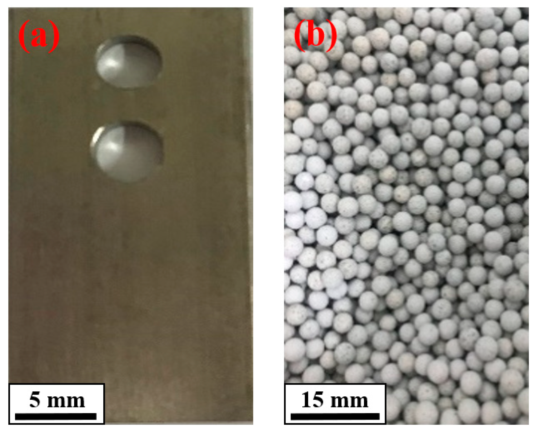
2.1. Material Preparation

The size of 304 stainless steel specimens used in this study was 30 mm × 15 mm × 3 mm, as shown in Figure 1a. The diameter of the particles was about 3 mm, as shown in Figure 1b. The chemical elements of 304 stainless steel is shown in Table 1, and the basic properties of 304 stainless steel is shown in Table 2 [14]. In order to improve the reliability of the experiment, ultrasonic cleaning of 304 stainless steel specimens was performed with anhydrous ethanol before erosion wear experiment. Brown corundum particles were used as abrasives in this experiment, and its physical properties is shown in Table 3.

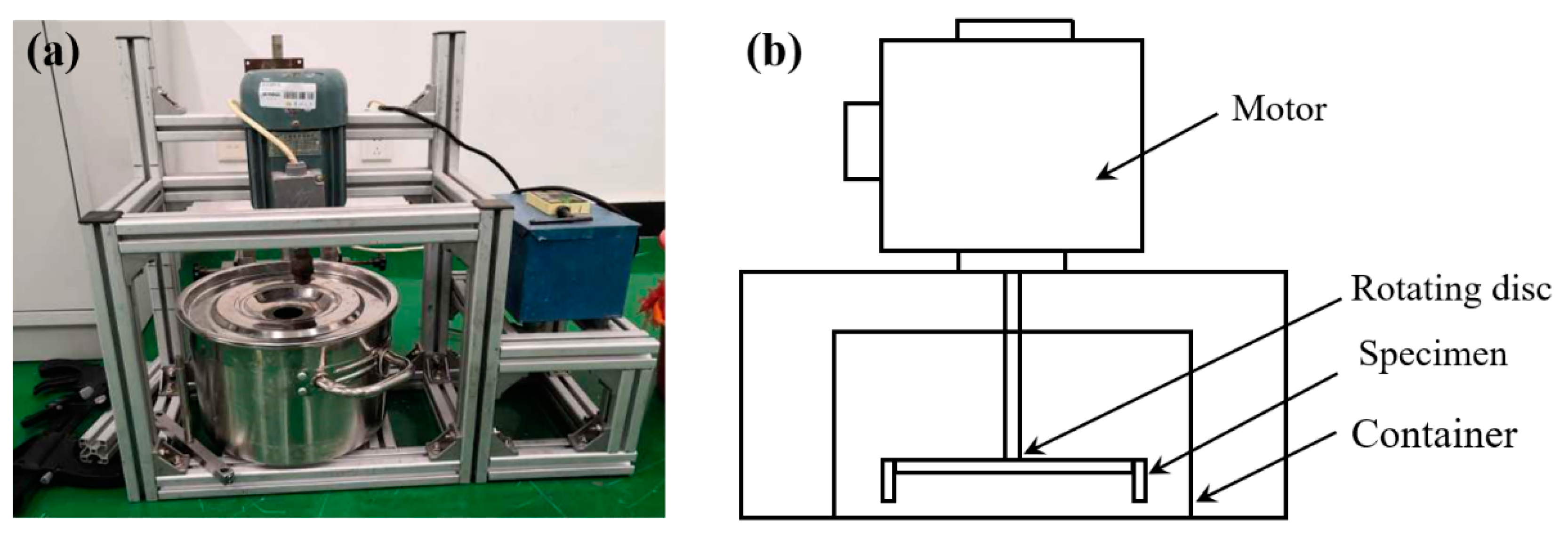
2.2. Erosion Wear Experiment

Combined with ASTM G73-10 standard [15], a rotary erosion wear test device was designed, and the physical image and schematic diagram of the rotating erosion wear test device are shown in Figure 2 [16,17]. The specimens are bolted to both sides of the turntable. The rotating disc drives the movement of the slurry. The solid particles in the slurry will impact the specimens continuously, and then cause the wear of the specimens. In this device, 3.375 kg of brown corundum particles and 1.125 kg of water were used to configure a slurry with a mass fraction of 75%. The slurry was poured into the container.
To balance the equipment, one nonworn specimen was installed on the left and right sides of the rotating disc, respectively. The layout is also presented in Figure 2b. The power supply was inserted and the frequency of the motor was adjusted to 18.1 Hz, as well as the rotation rate of the motor was 500 r/min. In this study, the speed of the turntable is 1380 r/min, and the diameter of the turntable is 195 mm. Under these conditions, the specimens were rotated clockwise for 5 h. The ultrasonic cleaner was used to clear the specimens and the drying box was used to dry the specimens.

2.3. Microstructural Observation

After the erosion wear experiment, the specimens were cleaned, sliced and polished. The surface morphologies of the specimens were observed by a SEM (JSM-6510, JEOL, Tokyo, Japan). The metallographic structures of the specimens were characterized by an optical microscope (OM) (VHX-700FC, KEYENCE Co., Ltd., Osaka, Japan). The composition (volume fraction) of the corrosive was 75% HCl and 25% HNO3, as well as the corrosion time was 15 s.
Moreover, the microstructure of the specimens was investigated by a TEM (JEOL 2100, JEOL, Tokyo, Japan) working at 200 kV. The preparation of TEM sample includes sampling, polishing, slicing and thinning, and the detailed preparation processes of TEM sample are as follows. (i) Grinding the unworn side of the sample to the thickness about 50–80 μm. (ii) Slicing the thinned sample, and punching the eroded area into a round piece with diameter of 3 mm with a perforator. (iii) Using 5% perchloric acid and 95% ethanol to prepare a double spray. (iv) Putting the 304 stainless steel small disc on the tenupol-5 electropolishing instrument to reduce the thickness to about 30 μm, thus taking out the specimen when it is perforated. (v) Storing the perforated specimens in acetone solution, then drying and observing the TEM sample.

2.4. Microhardness Measurement

In order to analyze the change of surface microhardness of the specimens after erosion wear, a CRATE 930 Vickers hardness tester (Dongguan Sinowon Precision Instrument Co., Ltd., Shenzhen, China) was used to measure the surface microhardness. The applied force was 9.8 N, and the dwell time was 15 s. For different area positions, the average value of five test points was selected as the final microhardness result.

3. Results and Discussion

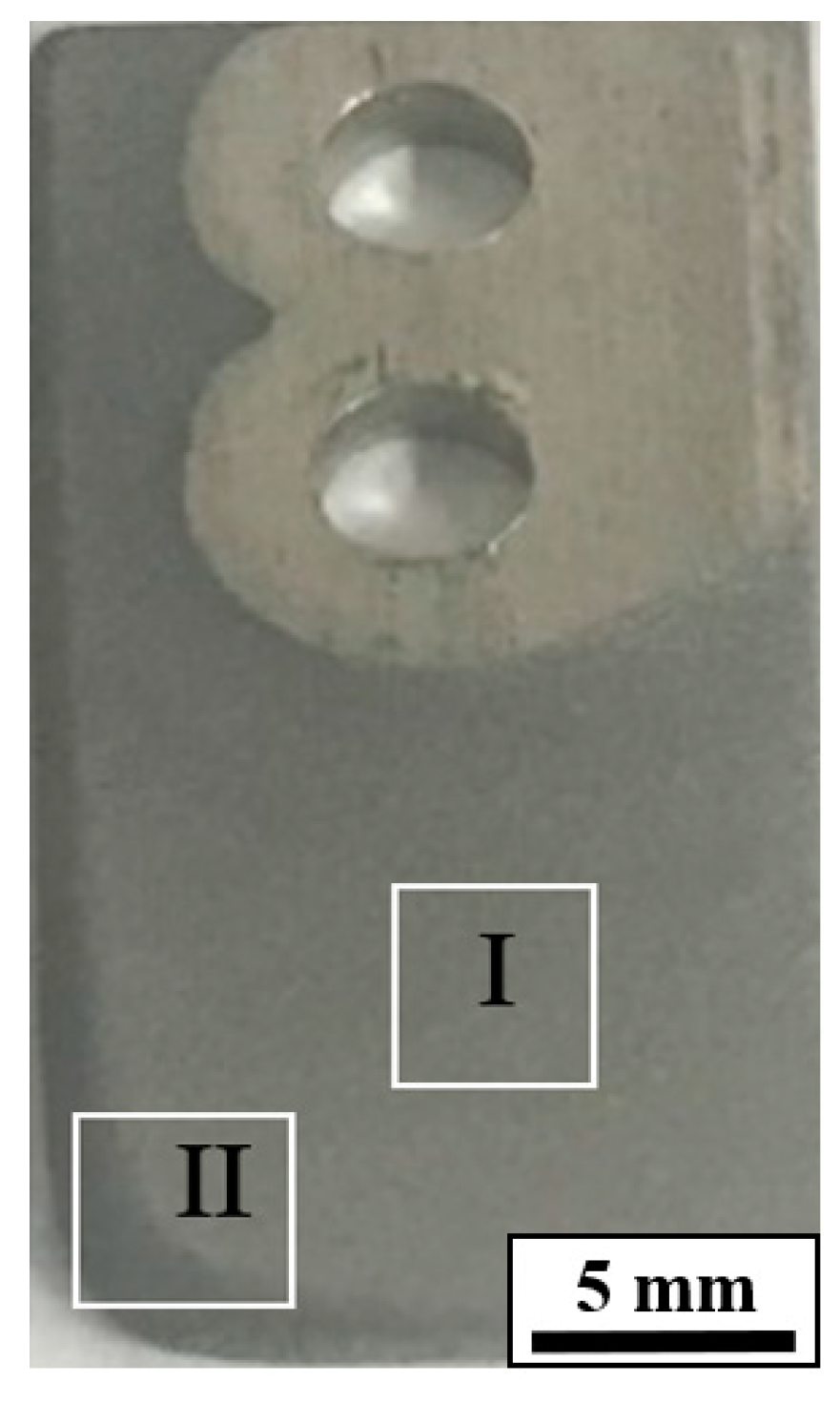
3.1. Worn Morphology Analysis

The shape of the worn 304 stainless steel specimen is shown in Figure 3. Due to the specimen rotates clockwise, the wear on the left side of the specimen was more serious than that on the right side. The original right angle was changed into an arc shape on the left side, and the wear was the most severe on worn surface II at the lower left corner. From the lower left corner to the upper right corner, the wear degree gradually decreases. The upper right corner has almost no wear. That’s because this part has little direct contact with particles due to the presence of bolts. Because the wear was severe on the worn surface I and II, thus the two surfaces were selected for observing the morphologies to analyze the erosion wear mechanism.
Figure 4 presents the SEM morphologies of 304 stainless steel specimen on worn surface I, and Figure 4b is the enlarged view of the area b in Figure 4a. As shown in Figure 4a, there is obvious cutting and abrasive on the worn surface with few craters [18,19]. As can be seen from Figure 4b, some obvious cutting with different lengths and lots of ploughing were observed. Moreover, there was obvious plastic accumulation around the ploughing, which was consistent with excellent resistance to plastic deformation of 304 stainless steel.
Figure 5 shows the surface morphologies on the worn surface II, while Figure 5b is the enlarged view of the area b in Figure 5a. It can be seen from Figure 5a that the whole worn surface has obvious deformation and no obvious craters on the worn surface II. As can be seen from Figure 5b that much shorter and deeper cutting, as well as a small amount of ploughing were found, which indicated that the erosion wear morphology was mainly short cutting. Worn surface II was accompanied by a small amount of debris that will be spalled, the size of the debris was different, about 20~50 μm. Some debris with different sizes was distributed on the worn surface II, which indicated that the wear was more serious than that on worn surface I.
After erosion wear, the surface morphologies on the worn surface I and II of 304 stainless steel was slightly different. However, the surface morphologies are mainly manifested as cutting and ploughing [20]. During the erosion wear process, the 304 stainless steel specimen moved circularly with the turntable, which made the surrounding slurry move together. However, the relative movement of the slurry and the sample caused the particles that were in the slurry to have an impact effect on the specimen, which was the fundamental reason on the wear of the 304 stainless steel specimen. The relative motion between the specimen and the particle can be divided into two parts, which includes the tangential motion and the normal motion. The tangential motion is parallel to the contact surface and the normal motion is perpendicular to the contact surface, as shown in Figure 6. In particular, the tangential motion of the particle can produce the cut effect on the contact surface, and the normal motion can produce the pressure effect on the contact surface.
The erosion wear failure process of 304 stainless steel is shown in Figure 7. It is clear that the N direction represents the normal direction, while the T direction represents the tangential direction. As can be seen in Figure 7a, the particle in the slurry is in contact with the surface of the specimen, and forms a low angle. The normal movement makes particle press into the contact surface, and the tangential movement of particle produces abrasive on the contact surface. As shown in Figure 4 and Figure 5, the surface material of 304 stainless steel was cut to form debris and leaves an obvious groove on the contact surface [21]. In Figure 7b, when the particle cannot form a low angle with the contact surface, the erosion angle becomes larger, leading to the weakness of the tangential effect, and the tangential movement of particle produces ploughing on the contact surface. As shown in Figure 4 and Figure 5, the surface material of the ploughed specimen accumulates forward along the direction of particle movement and leaves the groove. The material on both sides of the groove turns outward to form plastic accumulation of different degrees, which corresponds to step 2 in Figure 7b. Under the effect of the repeated ploughing, the plastic accumulation deforms repeatedly, and the plasticity of plastic accumulation surface layer exhausts gradually, which finally flakes off into debris. When the impact angle between particle and contact surface is close to 90°, the normal movement of the particle causes the particle to be pressed into the contact surface, and the material at the pressing point is extruded, while the tangential movement of the particle has little effect at this time. As shown in Figure 4, a crater is formed on the contact surface which corresponds to step 3 in Figure 7c. Then, the extruded material is spalled under the cut effect of continuous particles. Therefore, the erosion wear failure mechanism is cutting and spalling caused by plastic deformation.

3.2. Microstructural Evolution Analysis

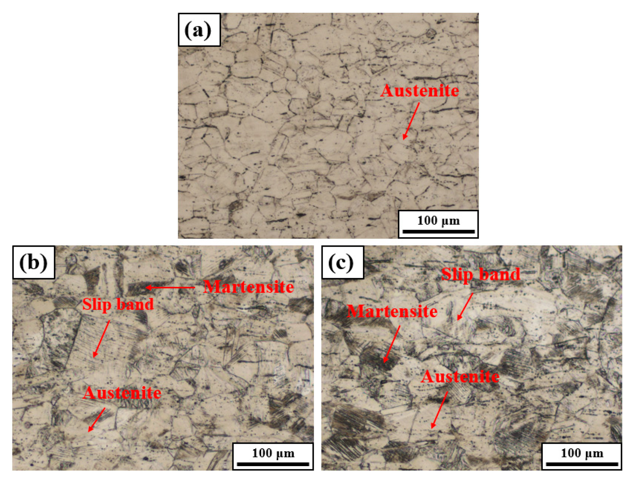
3.2.1. Metallographic Structure

On the basis of morphologies analysis, OM was carried out on metallographic observation of the nonworn and worn surface of the 304 stainless steel specimen. The metallographic images are shown in Figure 8.
Figure 8a is the metallographic image of the nonworn 304 stainless steel specimen, and it can be seen that 304 stainless steel is a single austenite structure before erosion wear [22]. Figure 8b shows the phases on the worn surface I, while Figure 8c shows the phases of the worn surface II. After erosion wear, martensite was found on both worn surface I and II [23]. Both austenite and martensite exist on the worn surface, which indicates that martensitic transformation occurs during the erosion wear process [24,25,26]. Moreover, the content of martensite on worn surface I shown in Figure 8b is a little lower than that on the worn surface II shown in Figure 8c. That’s because the wear condition of the worn surface I is less severe than the worn surface II. As shown in Figure 8b,c, there are some slip bands on the worn 304 stainless steel specimen, and the slip bands are an important feature of plastic deformation [27].

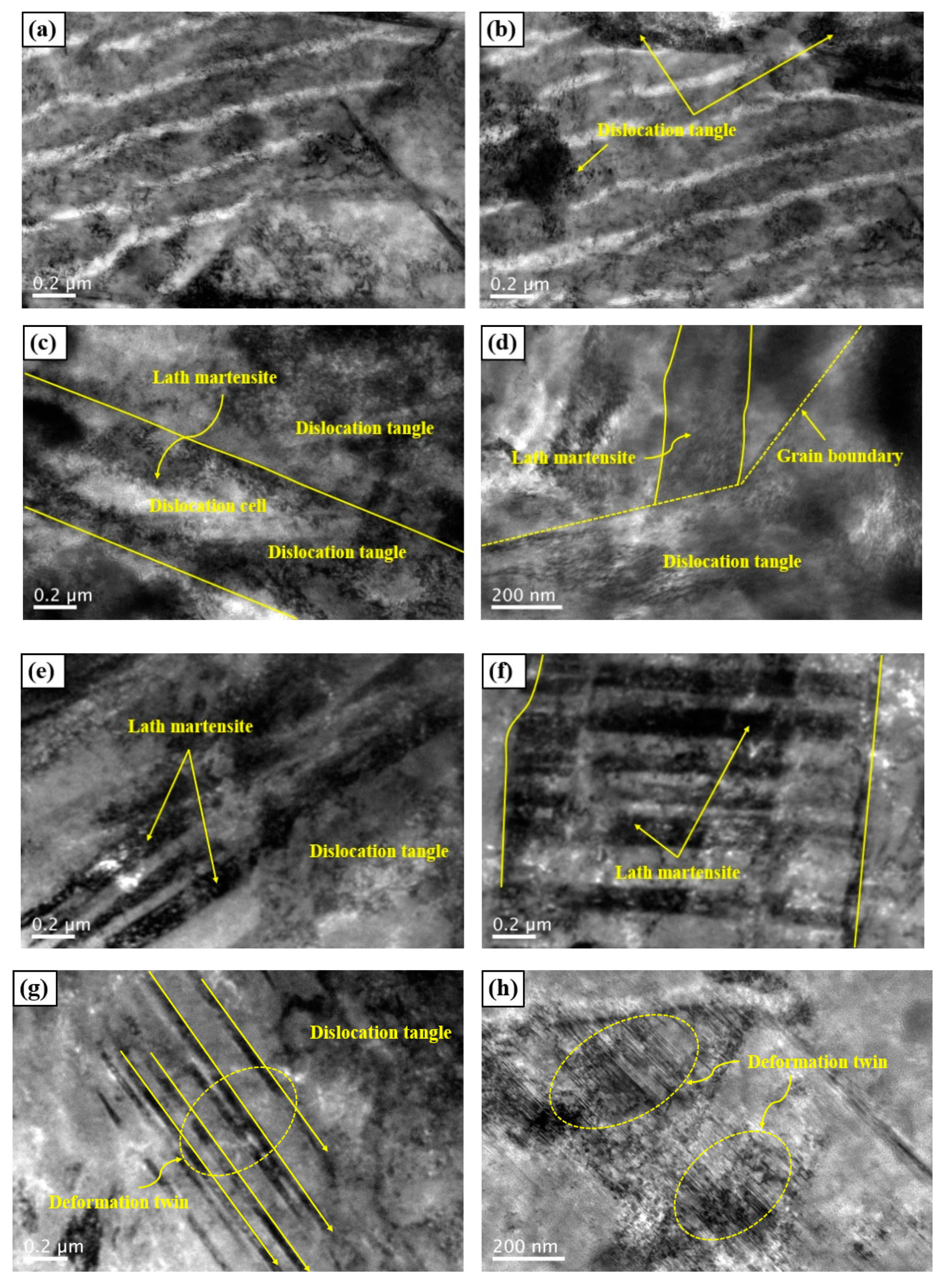
3.2.2. TEM Observation

The TEM images of worn 304 stainless steel specimens are shown in Figure 9. As shown in Figure 9a,b, except for some dislocation structures, no martensite was found in the original material. Figure 9c,d presents the microstructures on worn surface I. It can be observed that the presence of some lath martensite structures after erosion wear. The selected-area electron diffraction (SAED) pattern of Figure 9d is given in Figure 9i. It can be judged that the transformation martensite induced by erosion wear on worn surface I is α’-martensite. Meanwhile, there are many interacting dislocation structures in the lath α´-martensite, and these dislocation structures are mainly dislocation tangles and dislocation cells. Dislocation tangles are caused by dislocation motion and interaction [28]. The dislocations and dislocation entanglement have defects, which provide favorable conditions for the formation of martensite.
Furthermore, Figure 9e–h shows the TEM morphologies at the location of the worn surface II. As can be seen from Figure 9e,f that a large number of interacting dislocations constitute the lath martensite. However, the width of martensite in this area is about 100 nm, which is significantly smaller than 500 nm on the worn surface I. That is mainly due to the worn surface II undergoing more severe plastic deformation, while the smaller martensite width is beneficial to improve the hardness and wear resistance. Also, it can be clearly seen from Figure 9g,h that a large number of deformation twins are also found on the worn surface II [29]. On the worn surface II, the deformation for 304 stainless steel was the coordination of dislocation and twinning. Severe plastic deformation induced by erosion wear leads to the proliferation and slippage of dislocations. The dislocation structure is concentrated near the twin boundary, and the twin boundary will hinder the slip and movement of the dislocation.
In addition, the SAED patterns of Figure 9f,h are presented in Figure 9j,k. It can be judged that the transformation martensite induced by erosion wear on the worn surface II are α′-martensite and ε-martensite. Therefore, the transformation on the worn surface II of the 304 stainless steel specimens was the coordination of α´-martensite and ε -martensite.

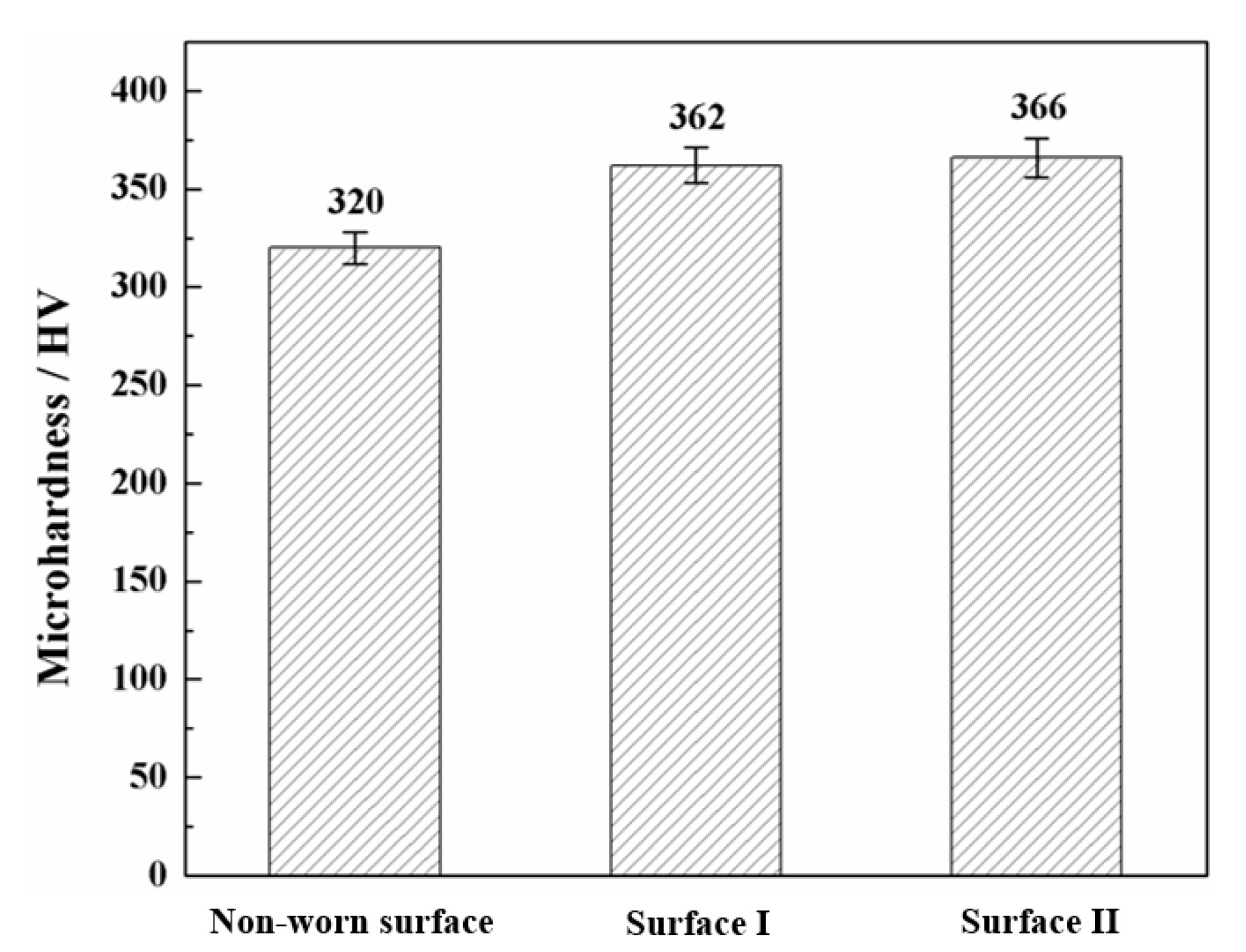
3.3. Microhardness Measurement

In order to investigate the effect of martensite transformation on the wear resistance, the surface microhardness of the specimen before and after wear was tested. The comparison results of surface microhardness of the sample before and after wear are shown in Figure 10. Before erosion wear, the surface microhardness of 304 stainless steel is 320 HV. After erosion wear, the hardness of the worn surface I and II increased to 362 HV and 366 HV, respectively. Compared with the samples before erosion and wear, the microhardness of the worn surface I and II was increased by 13.13% and 14.38%, respectively. Thus, it can be summarized that the hardness of 304 stainless steel surfaces becomes higher after martensitic transformation. The hardness increases with increasing the martensite content. Thus, a higher volume fraction of the martensite phase on worn surface II leads to a higher surface hardness.
Meanwhile, it can be seen from Figure 9 that the substructures of lath martensite and lamellar martensite induced by erosion wear are dislocations and deformation twins. The effects of dislocation density and grain size on the resistance to plastic deformation can be reflected by the following equation [30].
σ = σ 0 + k d 1 / 2 + α G b ρ 1 / 2
where σ is the resistance to plastic deformation, σ 0 is a friction stress, k is the Hall–Petch constant, d is the grain size, α is a constant, G is the shear modulus, b is the burgers vector, ρ is the dislocation density. According to the microstructures of worn surface II shown in Figure 9, the substructure of martensite consists of dislocation structures and deformation twins. It is obvious from Equation (1) that the dislocation proliferation and refined grain introduced by wear process are beneficial to improve the hardness of the processed materials.

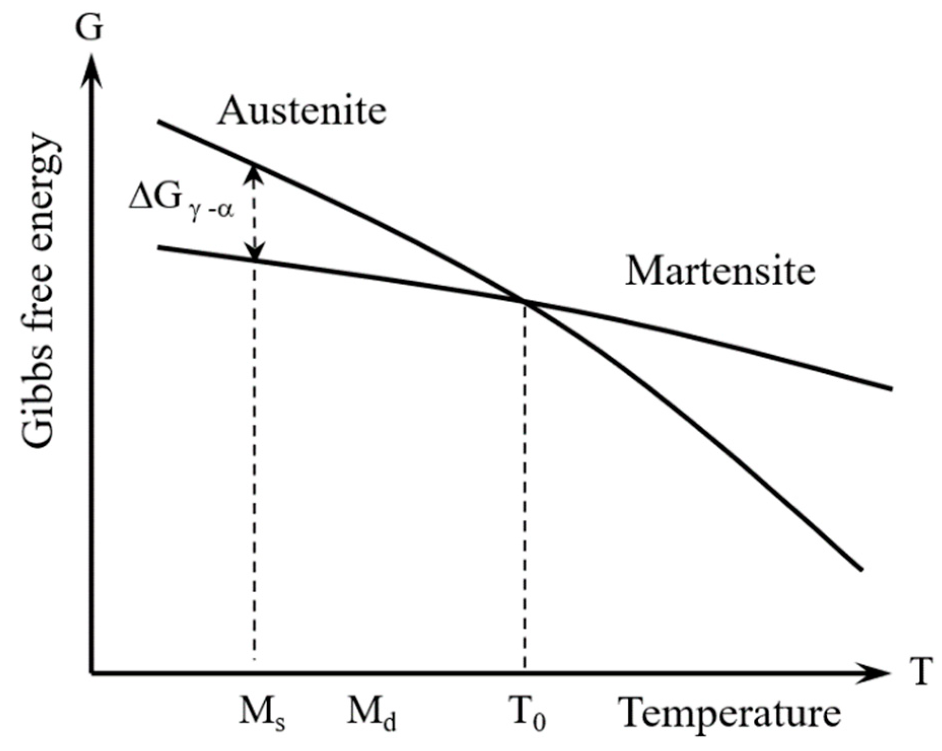
3.4. Formation Mechanism of Martensite Transformation

During the erosion wear process, the phase transformation of the austenite to the martensite can be explained by phase transformation driving force [31,32]. Figure 11 is a diagram of the relationship between Gibbs free energy and the temperature of austenite and martensite. In the process of martensite transformation, the austenite is the parent phase and the martensite is the new phase. It can be seen that the Gibbs free energy of martensite and austenite are equal at the critical temperature T0 in Figure 11. It is impossible for martensite transformation to occur when the temperature is higher than T0. Above the T0 temperature, austenite is in a stable region, it is due to the phase transformation from high Gibbs free energy to low free energy. Martensite transformation begins at a certain temperature, which is lower than T0, expressed as Ms [33]. Ms is the martensite transformation temperature, and the difference of Gibbs free energy ΔGα-γ, which is the phase transformation driving force between the parent phase and the new phase. When the temperature is between Ms and T0, the difference of Gibbs free energy between the two phases is small, and the accumulated energy is not enough for phase transformation. During the erosion wear process, the collision of particles produces heat energy, thus the temperature inside the container increases gradually and the surface temperature of the specimen is slightly higher than the room temperature. However, the surface of the specimen bears severe plastic deformation, the external mechanical energy compensates for the free energy difference. When the superposition value reaches the ΔGα-γ, the deformation-induced martensite transformation takes place between the martensite start temperature Ms and martensite deformation temperature Md [34]. At this time, the temperature Md is obviously higher than Ms, which indicates that plastic deformation improves the temperature of martensite transformation.
Additionally, based on the assumption that the shear band junction is the main mechanism of deformation-induced martensite formation, Olson and Cohen [35] proposed an analytical formula for estimating the volume fraction of the martensite phase. The formula is a function of plastic strain, as follows:
f a = 1 - exp { - β [ 1 - exp ( - α ε ) ] n }
where f a is the volume fraction of the martensite, β and α are the temperature-dependent parameter, ε is the equivalent plastic strain, n is a material-dependent constant. It can be seen from Equation (2) that the volume fraction of martensite transformation increases with increasing strain and decreasing temperature. Additionally, Smaga et al. explored the deformation-induced martensitic transformation in metastable austenitic steels, and came to the same conclusion [36]. Therefore, the severe plastic deformation caused by erosion wear has a critical contribution to the martensite transformation.
In order to obtain a better understanding of the martensitic transformation process of 304 stainless steel during the erosion wear process, a simple martensitic transformation diagram is shown in Figure 12. As presented in Figure 12a, before the erosion wear experiment, some low-density dislocations structures existed in austenite crystal. As shown in Figure 12b, 304 stainless steel was cut and ploughed by impact particles during the process of erosion wear, which caused serious plastic deformation and lead to the formation of slip bands and slip lines. Moreover, the slip band is composed of a group of parallel slip lines. As displayed in Figure 12c, some crystal planes between the slip lines slip to form slip planes, and high-density dislocations move along the slip planes [37], dislocations movement results in the formation of lath martensite between the slip lines shown in Figure 8b. It can be concluded that the movement of the dislocations is the necessary condition for martensitic transformation. The stronger dislocation interaction on different slip planes is, the more likely martensitic transformation will occur. Therefore, due to the presence of particles in the slurry, the high-density dislocations in 304 stainless steel move along the slip planes between the slip lines under the effect of dislocation movement. Eventually, austenite with high energy and unstable structure is transformed into martensite with low energy and stable structure.

4. Conclusions

The failure mechanism and phase transformation of 304 stainless steel during erosion wear process were investigated in this study. Some significant conclusions can be acquired from the analysis of the experimental results.
(1)
The erosion wear of 304 stainless steel was caused by the relative movement of 304 stainless steel and slurry. The erosion wear surface morphologies of 304 stainless steel were mainly abrasive and ploughing, and the erosion wear failure mechanisms were mainly cutting and spalling caused by plastic deformation.
(2)
Before erosion wear, 304 stainless steel was mainly composed of austenite. After erosion wear, both austenite and martensite exist on the worn surface, which indicated that erosion wear caused martensitic transformation. According to the theory of phase transformation driving force, the plastic deformation improved the martensite transformation temperature, which lead to martensitic transformation occurring above MS.
(3)
Compared with the sample without erosion wear, the microhardness of the worn surface I and II was increased by 13.13% and 14.38%, respectively. That’s mainly due to the higher density of dislocation structure, deformation twin and martensite induced by the more severe plastic deformation on the worn surface II.
(4)
During the martensite transformation process, there are many dislocation structures during 304 stainless steel. The slip bands appear on the surface of 304 stainless steel during the process of erosion wear, and high-density dislocations move along the slip planes between the slip lines, which leads to the formation of martensite between the slip lines.

Author Contributions

Y.Y., J.L. and L.L. provided the investigating theme and offered several suggestions on the experiments. X.L. carried out the experiments and wrote the paper. Y.Y., J.L. and L.L. provided some advice on the writing of the paper. All authors have read and agreed to the published version of the manuscript.

Funding

The authors are grateful for the support provided by the National Key R&D Program of China (NO. 2018YFC0808800), the Natural Science Foundation of Jiangsu Higher Education Institutions (NO. 17KJA460002), the “Six Talent Peaks” of Jiangsu Province (NO. GDZB-002).

Conflicts of Interest

The authors declare no conflict of interest.

References

  1. Qian, H.; Liu, S.; Wang, P.; Huang, Y.; Lou, Y.; Huang, L.; Jiang, C.; Zhang, D. Investigation of microbiologically influenced corrosion of 304 stainless steel by aerobic thermoacidophilic archaeon Metallosphaera cuprina. Bioelectrochemistry 2020, 136, 107635. [Google Scholar] [CrossRef] [PubMed]
  2. Yang, X.; Liu, M.; Liu, Z.; Du, C.; Li, X. Failure analysis of a 304 stainless steel heat exchanger in liquid sulfur recovery units. Eng. Fail. Anal. 2020, 116, 104729. [Google Scholar] [CrossRef]
  3. Wu, C.L.; Zhang, S.; Zhang, C.H.; Zhang, H.; Dong, S.Y. Phase evolution and cavitation erosion-corrosion behavior of FeCoCrAlNiTix high entropy alloy coatings on 304 stainless steel by laser surface alloying. J. Alloys Compd. 2017, 698, 761–770. [Google Scholar] [CrossRef]
  4. Tobi, A.L.M.; Kamdi, Z.; Ismail, M.I.; Nagentrau, M.; Roslan, L.N.H.; Mohamad, Z.; Omar, A.S.; Latif, N.A. Abrasive Wear Failure Analysis of Tungsten Carbide Hard facing on Carbon Steel Blade. In IOP Conference Series: Materials Science and Engineering; IOP Publishing: Bristol, UK, 2017; Volume 165, p. 012020. [Google Scholar]
  5. Mann, B.S.; Arya, V. Abrasive and erosive wear characteristics of plasma nitriding and HVOF coatings: Their application in hydro turbines. Wear 2001, 249, 354–360. [Google Scholar] [CrossRef]
  6. Zhang, J.; Kang, J.; Fan, J.; Gao, J. Research on erosion wear of high-pressure pipes during hydraulic fracturing slurry flow. J. Loss Prev. Process Ind. 2016, 43, 438–448. [Google Scholar] [CrossRef]
  7. Krishnamurthy, N.; Murali, M.S.; Venkataraman, B.; Mukunda, P.G. Characterization and solid particle erosion behavior of plasma sprayed alumina and calcia-stabilized zirconia coatings on Al-6061 substrate. Wear 2012, 274, 15–27. [Google Scholar] [CrossRef]
  8. Schino, A.D.; Salvatori, I.; Kenny, J.M. Effects of martensite formation and austenite reversion on grain refining of AISI 304 stainless steel. J. Mater. Sci. 2002, 37, 4561–4565. [Google Scholar] [CrossRef]
  9. Bahri, A.; Guermazi, N.; Elleuch, K.; Urgen, M. On the erosive wear of 304L stainless steel caused by olive seed particles impact: Modeling and Experiments. Tribol. Int. 2016, 102, 608–619. [Google Scholar] [CrossRef]
  10. Huttunen-Saarivirta, E.; Kinnunen, H.; Tuiremo, J.; Uusitalo, M.; Antonov, M. Erosive wear of boiler steels by sand and ash. Wear 2014, 317, 213–224. [Google Scholar] [CrossRef]
  11. Singh, J.; Kumar, S.; Mohapatra, S.K. Optimization of Erosion Wear Influencing Parameters of HVOF Sprayed Pumping Material for Coal-Water Slurry. Mater. Today Proc. 2018, 5 Pt 3, 23789–23795. [Google Scholar]
  12. Gautam, V.; Kumar, A.; Prasad, L.; Patel, V.K. An Experimental Investigation on Slurry Erosion Wear Characteristics of Brass Alloy. Mater. Today Proc. 2017, 4, 9879–9882. [Google Scholar] [CrossRef]
  13. Wang, B.; Barber, G.C.; Qiu, F.; Zou, Q.; Yang, H. A review: Phase transformation and wear mechanisms of single-step and dual-step austempered ductile irons. J. Mater. Res. Technol. 2020, 9, 1054–1069. [Google Scholar] [CrossRef]
  14. Smag, M.; Boemke, A.; Daniel, T.; Klein, M.W. Metastability and fatigue behavior of austenitic stainless steels. In MATEC Web of Conferences; EDP Sciences: Ulis, France, 2018; Volume 165, p. 04010. [Google Scholar]
  15. ASTM G73-10, Standard test method for liquid impingement erosion using rotating apparatus [S]. Astm Int. 2010, 1–19. [CrossRef]
  16. Singh, G.; Singh, S.; Grewal, J.S. Erosion wear characterisation of DLC and AlCrN-based coated AISI-304/316 steels. Surf. Eng. 2018, 35, 304–316. [Google Scholar] [CrossRef]
  17. Li, T.Z.; Li, L.; Lu, H.; Parent, L.; Tian, H.; Chung, R.J.; Li, D.Y. Effect of trace Ni on the resistance of high-Cr cast iron to slurry erosion. Wear 2019, 426, 605–611. [Google Scholar] [CrossRef]
  18. Laguna-Camacho, J.R.; Marquina-Chávez, A.; Méndez-Méndez, J.V.; Vite-Torres, M.; Gallardo-Hernández, E.A. Solid particle erosion of AISI 304, 316 and 420 stainless steels. Wear 2013, 301, 398–405. [Google Scholar] [CrossRef]
  19. Nandre, B.D.; Desale, G.R. Study the Effect of Impact Angle on Slurry Erosion Wear of Four Different Ductile Materials. Mater. Today Proc. 2018, 5 Pt 2, 7561–7570. [Google Scholar] [CrossRef]
  20. Liang, C.G.; Xin-Mei, L.I.; Zhang, P.F. Erosion Wear Behavior of WC-12Co Coatings Prepared by APS. Surf. Technol. 2017, 9, 2. [Google Scholar]
  21. Swain, B.; Patnaik, A.; Bhuyan, S.K.; Barik, K.N.; Sethi, S.K.; Samal, S.; Mishra, S.C.; Behera, A. Solid particle erosion wear on plasma sprayed mild steel and copper surface. Mater. Today Proc. 2018, 5 Pt 3, 20403–20412. [Google Scholar] [CrossRef]
  22. Zhou, G.; Ding, H.; Yue, Z.; Li, N. Corrosion–erosion wear behaviors of 13Cr24Mn0.44N stainless steel in saline–sand slurry. Tribol. Int. 2010, 43, 891–896. [Google Scholar]
  23. Fu, Y.; Xiao, W.; Wang, J.; Ren, L.; Zhao, X.; Ma, C. Oxygen induced crystal structure transition of martensite in Ti–Nb–Fe alloys. Mater. Lett. 2020, 262, 127026. [Google Scholar] [CrossRef]
  24. Hou, Y.; You, W.; Pan, Z.; Lili, Y.U. Influence of rare earth nanoparticles and inoculants on performance and microstructure of high chromium cast iron. J. Rare Earths 2012, 30, 283–288. [Google Scholar] [CrossRef]
  25. Prakash, M.O.; Raghavendra, G.; Panchal, M.; Ojha, S.; Reddy, B.A. Effects of environmental exposure on tribological properties of Arhar particulate/epoxy composites. Polym. Compos. 2018, 39, 3012–3019. [Google Scholar] [CrossRef]
  26. Praveen, A.S.; Sarangan, J.; Suresh, S.; Channabasappa, B.H. Optimization and erosion wear response of nicrsib/wc-co hvof coating using taguchi method. Ceram. Int. 2016, 42, 1094–1104. [Google Scholar] [CrossRef]
  27. Lychagin, D.V.; Filippov, A.V.; Novitskaia, O.S.; Chumlyakov, Y.I.; Kolubaev, E.A.; Sizova, O.V. Friction-induced slip band relief of -Hadfield steel single crystal oriented for multiple slip deformation. Wear 2017, 374–375, 5–14. [Google Scholar] [CrossRef]
  28. Lu, J.Z.; Luo, K.Y.; Zhang, Y.K.; Sun, G.F.; Gu, Y.Y.; Zhou, J.Z.; Ren, X.D.; Zhang, X.C.; Zhang, L.F.; Chen, K.M.; et al. Grain refinement mechanism of multiple laser shock processing impacts on ANSI 304 stainless steel. Acta Mater. 2010, 58, 5354–5362. [Google Scholar] [CrossRef]
  29. Farias, F.; Alvarez-Armas, I.; Armas, A.F. On the strain-induced martensitic transformation process of the commercial AISI 304 stainless steel during cyclic loading. Int. J. Fatigue 2020, 140, 105809. [Google Scholar] [CrossRef]
  30. Li, J.; Zhou, J.; Sun, Y.; Feng, A.; Meng, X.; Huang, S.; Sun, Y. Study on mechanical properties and microstructure of 2024-T351 aluminum alloy treated by cryogenic laser peening. Opt. Laser Technol. 2019, 120, 105670. [Google Scholar] [CrossRef]
  31. Xu, C.; Hu, G.; Ng, W.Y. Relationship between the martensite phase transition and pitting susceptibility of AISI-321 stainless steel in acidic solutions of NaCl. Mater. Sci. 2004, 40, 252–259. [Google Scholar]
  32. Wang, Q.; Zhang, M.; Liu, W.; Wei, X.; Xu, J.; Chen, J.; Lu, H.; Yu, C. Cr or C controlled formation of transition martensite in dissimilar metal weld. Mater. Charact. 2019, 147, 434–442. [Google Scholar] [CrossRef]
  33. Guimarães, J.R.C.; Rios, P.R. The mechanical-induced martensite transformation in Fe–Ni–C alloys. Acta Mater. 2015, 84, 436–442. [Google Scholar] [CrossRef]
  34. Frölich, D.; Magyar, B.; Sauer, B.; Mayer, P.; Kirsch, B.; Aurich, J.C.; Skorupski, R.; Smaga, M.; Beck, T.; Eifler, D. Investigation of wear resistance of dry and cryogenic turned metastable austenitic steel shafts and dry turned and ground carburized steel shafts in the radial shaft seal ring system. Wear 2015, 328–329, 123–131. [Google Scholar]
  35. Ye, C.; Suslov, S.; Lin, D.; Cheng, G.J. Deformation-induced martensite and nanotwins by cryogenic laser shock peening of AISI 304 stainless steel and the effects on mechanical properties. Philos. Mag. 2012, 92, 1369–1389. [Google Scholar] [CrossRef]
  36. Smaga, M.; Walther, F.; Eifler, D. Deformation-induced martensitic transformation in metastable austenitic steels. Mater. Sci. Eng. A 2008, 483–484, 394–397. [Google Scholar] [CrossRef]
  37. Guo, M.; Long, Y.; Jie, Z.; Tong, L.; Li, M. Strain-induced martensitic transformation of particles in a copper-based composite and its effect on mechanical properties. Mater. Charact. 2016, 120, 109–114. [Google Scholar] [CrossRef]
Figure 1. (a) 304 stainless specimen, (b) brown corundum particles.
Metals 10 01427 g001
Figure 2. Schematic diagram of rotary erosion wear test device (a) physical image, (b) schematic diagram.
Metals 10 01427 g002
Figure 3. Macroscopic morphology of the worn specimen.
Metals 10 01427 g003
Figure 4. (a) SEM morphologies on worn surface I at 100 magnification, (b) Enlarged view of area b in (a) at 500 magnification.
Metals 10 01427 g004
Figure 5. (a) SEM morphologies on worn surface II at 100 magnification, (b) enlarged view of area b in (a) at 500 magnification.
Metals 10 01427 g005
Figure 6. Contact diagram of particle and specimen surface.
Metals 10 01427 g006
Figure 7. Diagram of 304 stainless steel erosion wear failure process. (a) schematic diagram of abrasive wear process, (b) schematic diagram of ploughing wear process and (c) schematic diagram of crater wear process.
Metals 10 01427 g007
Figure 8. Metallographic structures of the specimens before and after wear at 800 magnification. (a) Nonworn surface, (b) worn surface I and (c) worn surface II.
Metals 10 01427 g008
Figure 9. TEM images on different location of the worn specimens at 8000 magnification. (a,b) Nonworn surface (c,d) worn surface I, (eh) worn surface II, SAED patterns of (d,f,h) are given in (i,j,k), respectively.
Metals 10 01427 g009aMetals 10 01427 g009b
Figure 10. Comparison results of surface microhardness.
Metals 10 01427 g010
Figure 11. Diagram of relationship between Gibbs free energy and temperature of austenite and martensite.
Metals 10 01427 g011
Figure 12. Process diagram of martensite transformation. (a) Original state, (b) slip plane formation, (c) martensite formation.
Metals 10 01427 g012
Table 1. Chemical elements of 304 stainless steel used in this study.
NCSiMnCrNiSPFe
≤0.10≤0.08≤1.0≤2.018.0–20.08.0–10.5≤0.03≤0.035Bal
Table 2. Basic properties of 304 stainless steel used in this study.
Tensile Strength σ (MPa)Conditional Yield Strength σ0.2 (MPa)Elongation δ (100%)Reduction of Area Ψ (100%)Md30 in °C
≥520≥205≥40≥6012
Table 3. Physical properties of corundum particles.
Density/kg·m−3Diameter/mmPoisson’s RatioShear Modulus/Pa
26503.00.51.0 × 106
Publisher’s Note: MDPI stays neutral with regard to jurisdictional claims in published maps and institutional affiliations.

