Numerical Simulation and Experimental Validation of the Cladding Material Distribution of Hybrid Semi-Finished Products Produced by Deposition Welding and Cross-Wedge Rolling


 , , ,
, , ,  ,
,
Abstract
:
1. Introduction
1.1. Tailored Forming Approach
1.2. Welding and Forming
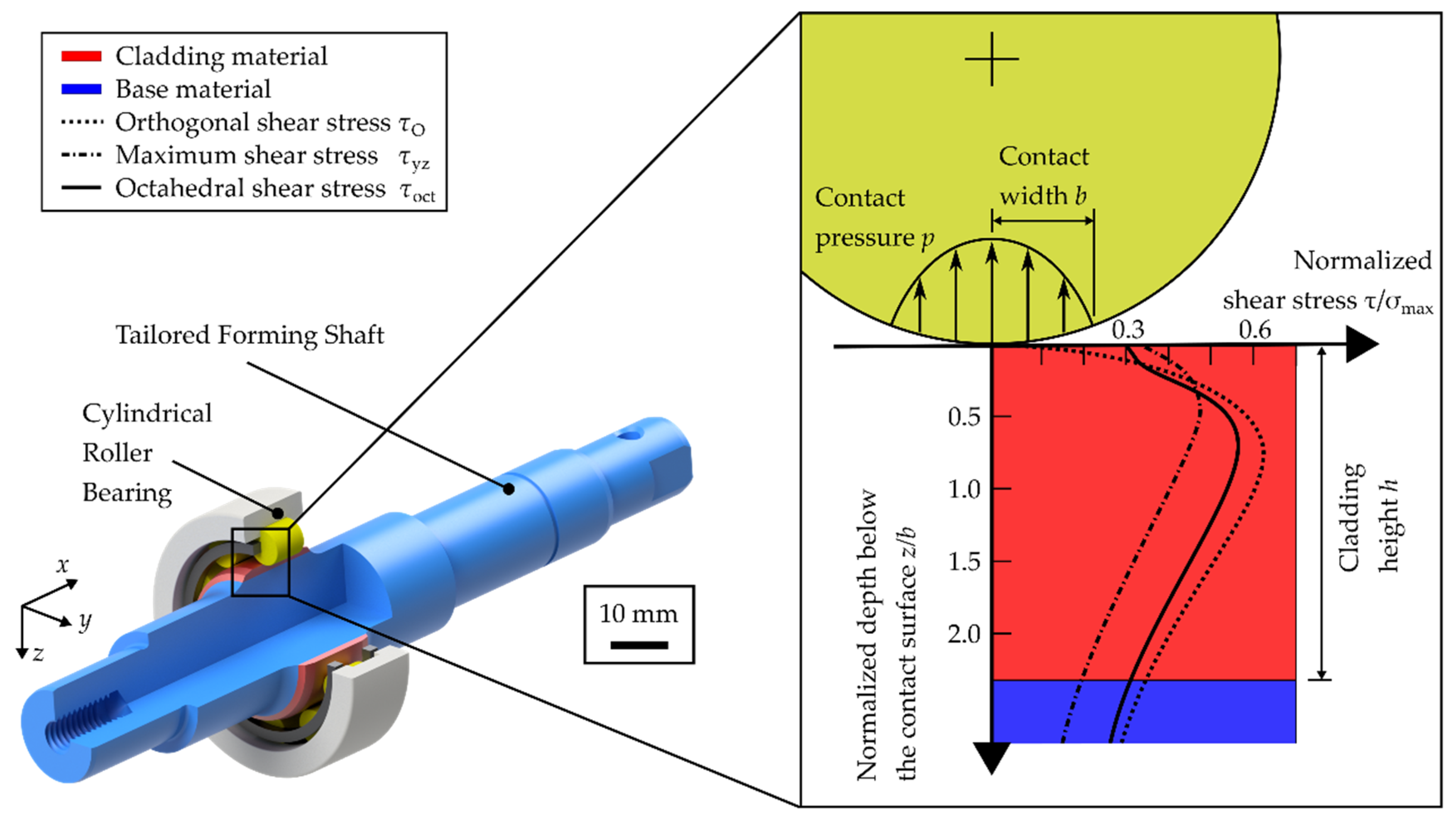
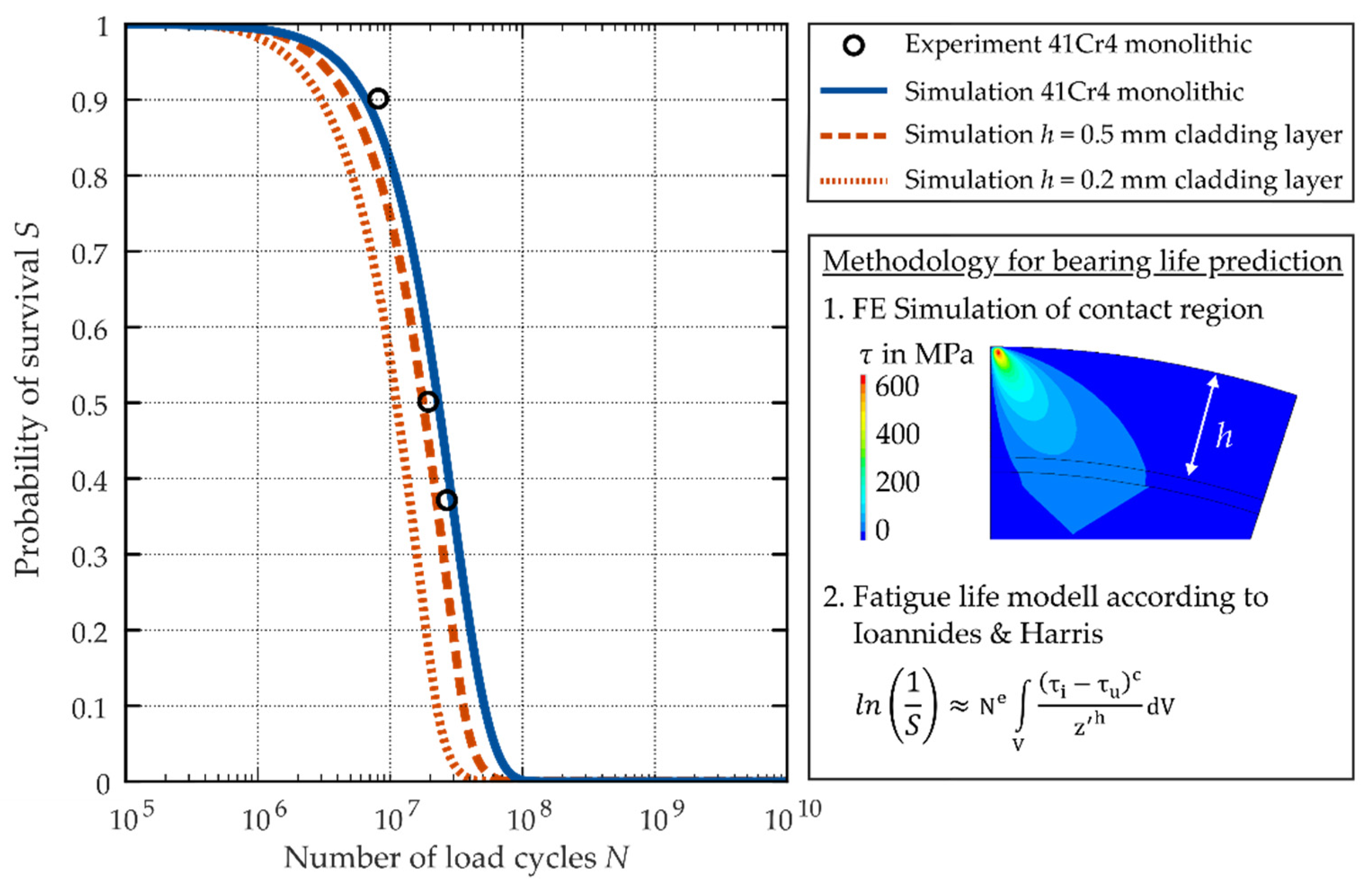
1.3. Bearing Fatigue Life of Tailored Forming Machine Elements
2. Materials and Methods
- Depending on the application, even a small amount of high-performance material may be sufficient to produce a multi-material component with a performance comparable to that of conventional manufacturing processes. However, the cladding layer in the region subject to rolling contact loading must not be too thin.
- The process must have an economically viable application rate and quality. This requires precise knowledge of the application and its loads.
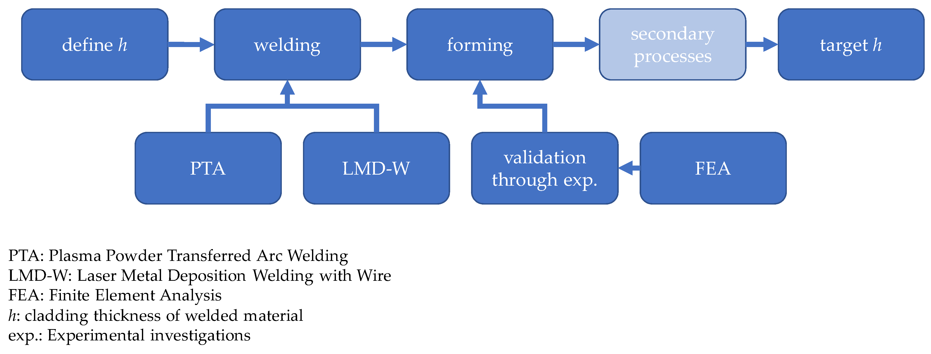
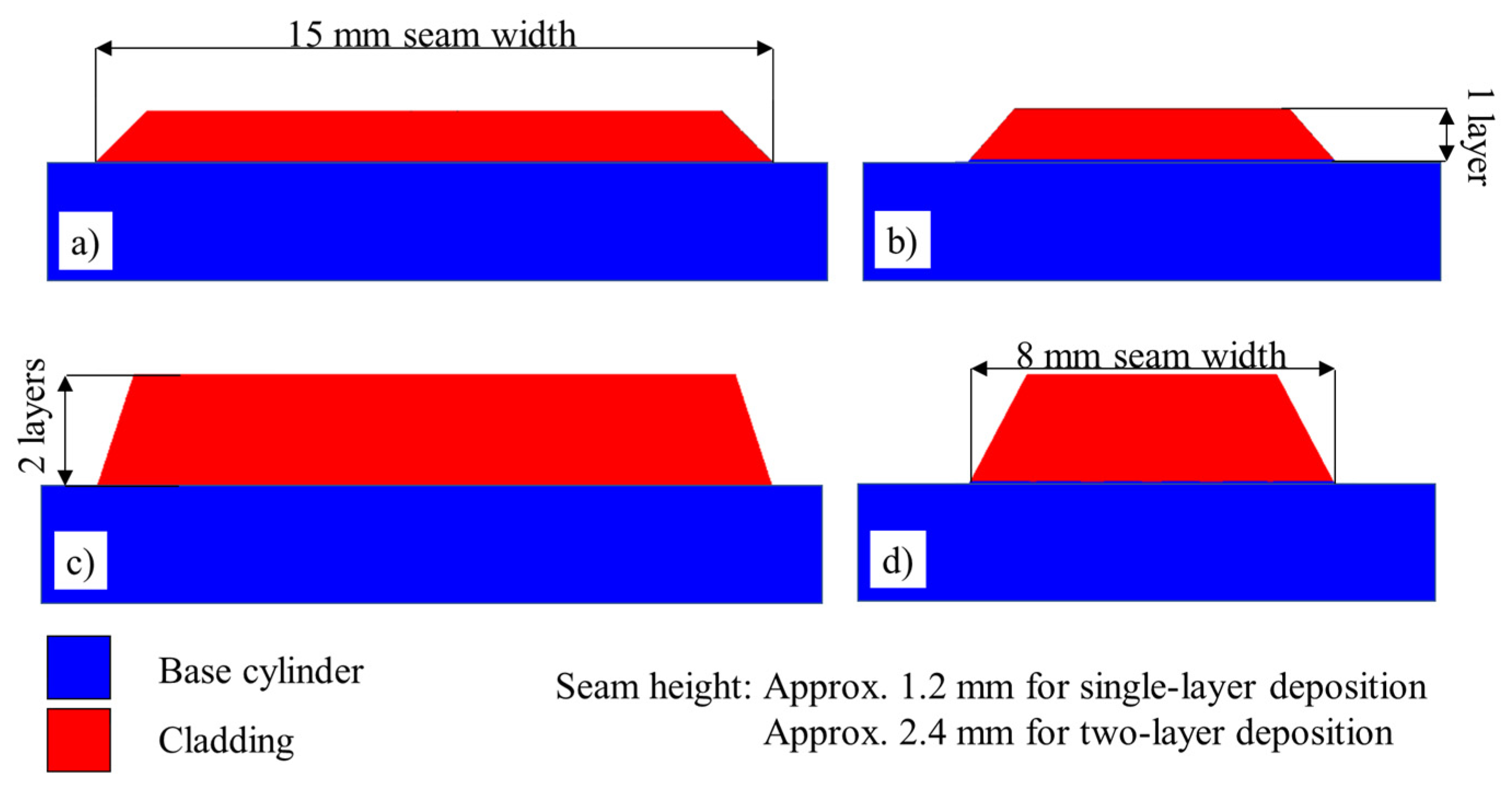
- It must be possible to set the layer height as the decisive target value for production within narrow limits.
2.1. Laser Metal Deposition Welding with Wire
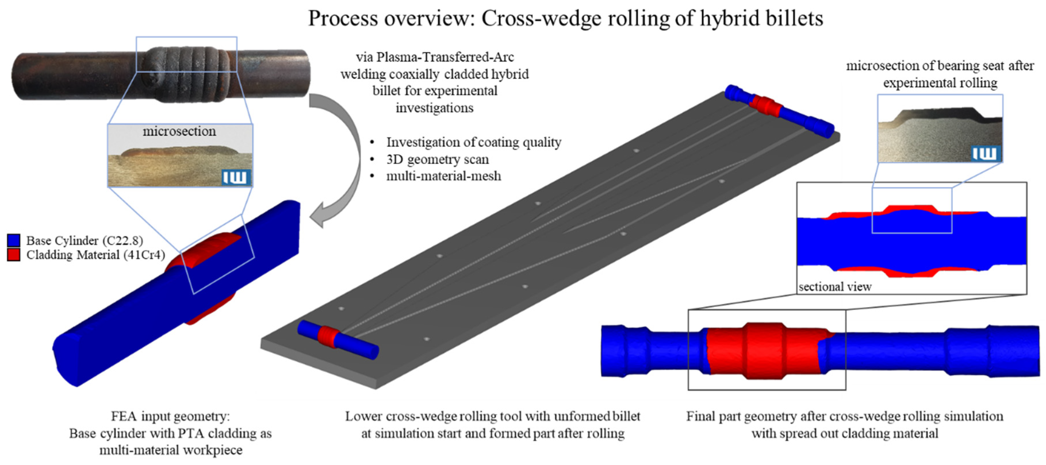
2.2. Plasma Powder Transferred Arc Welding
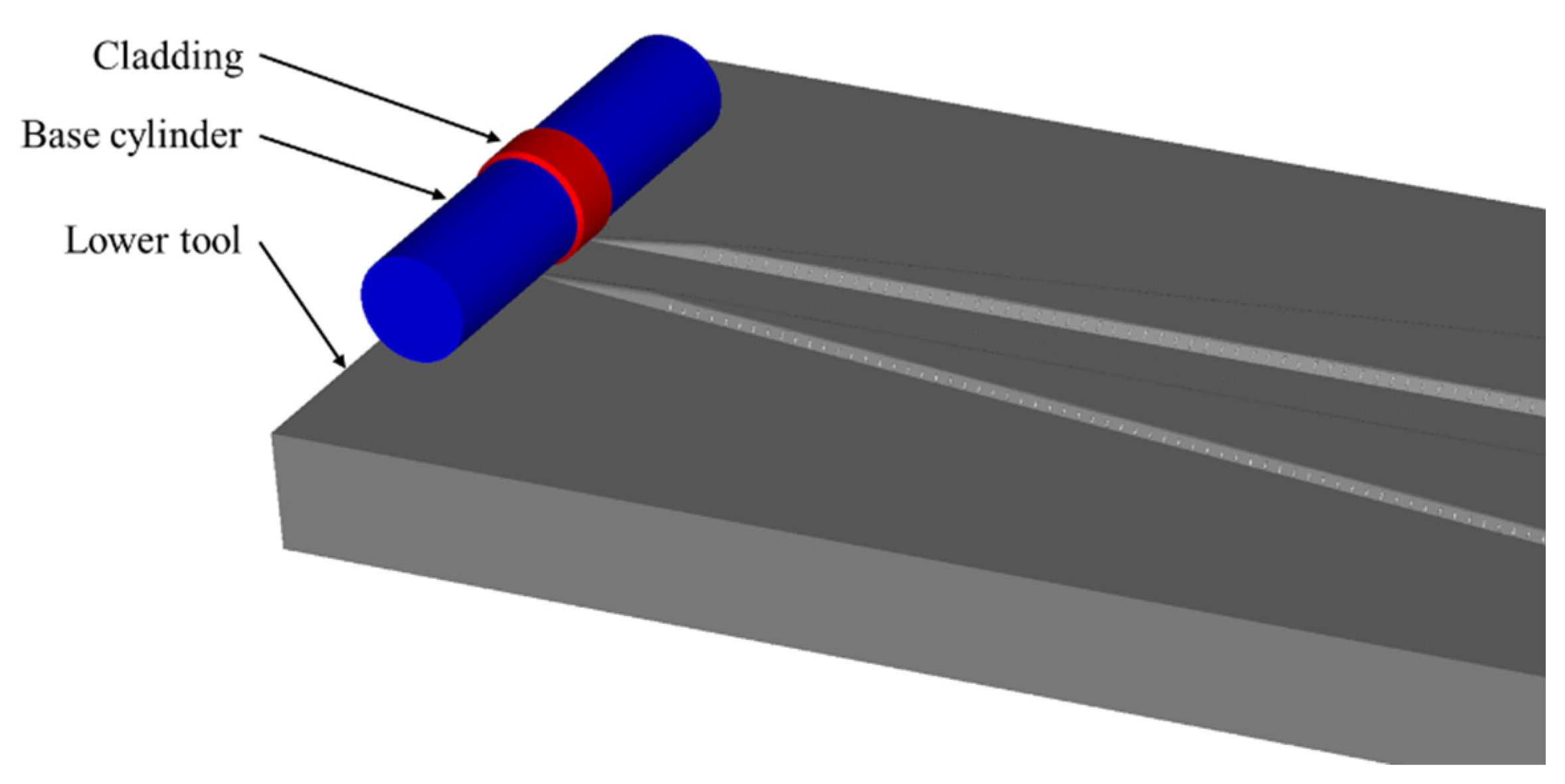
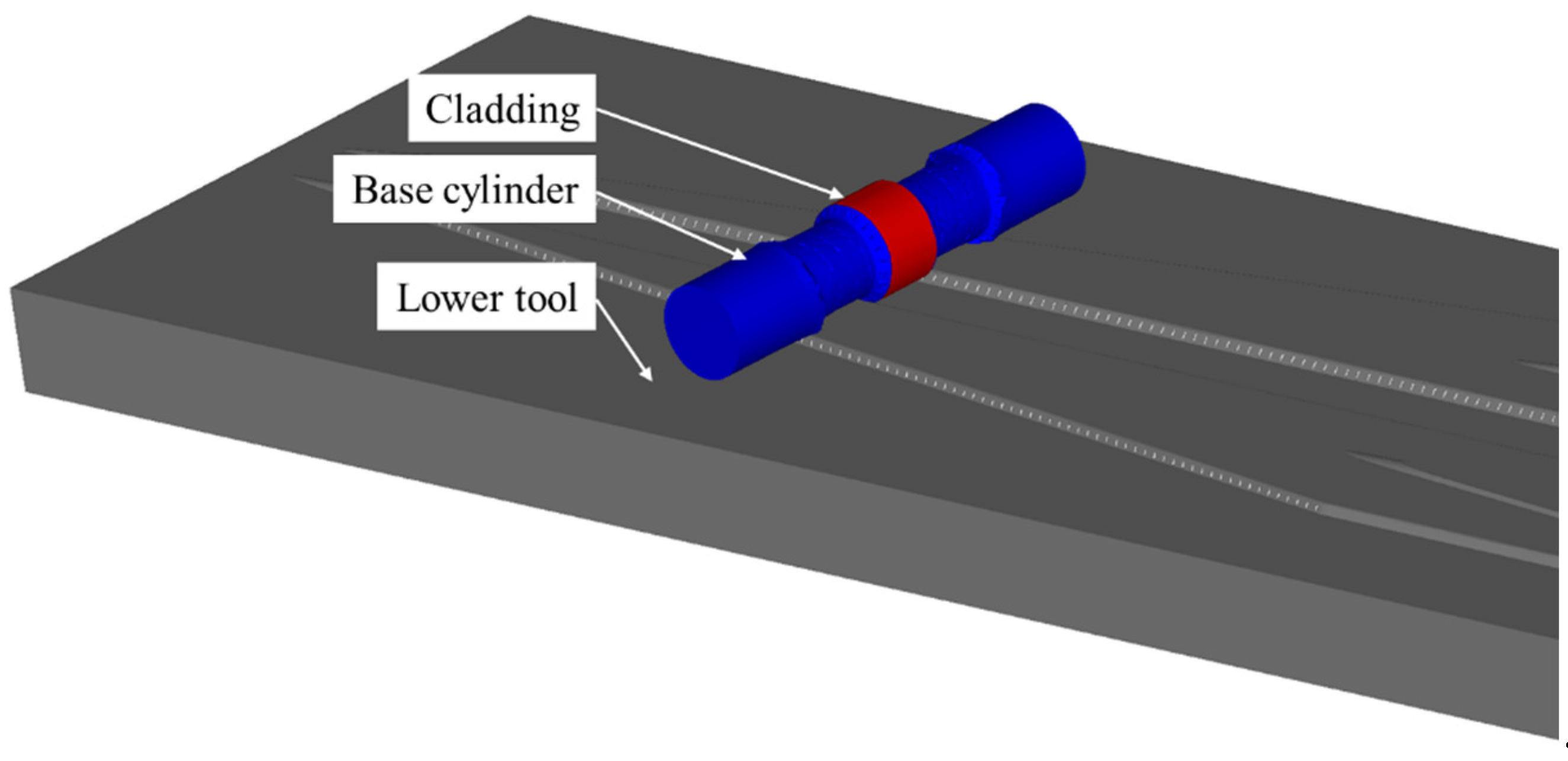
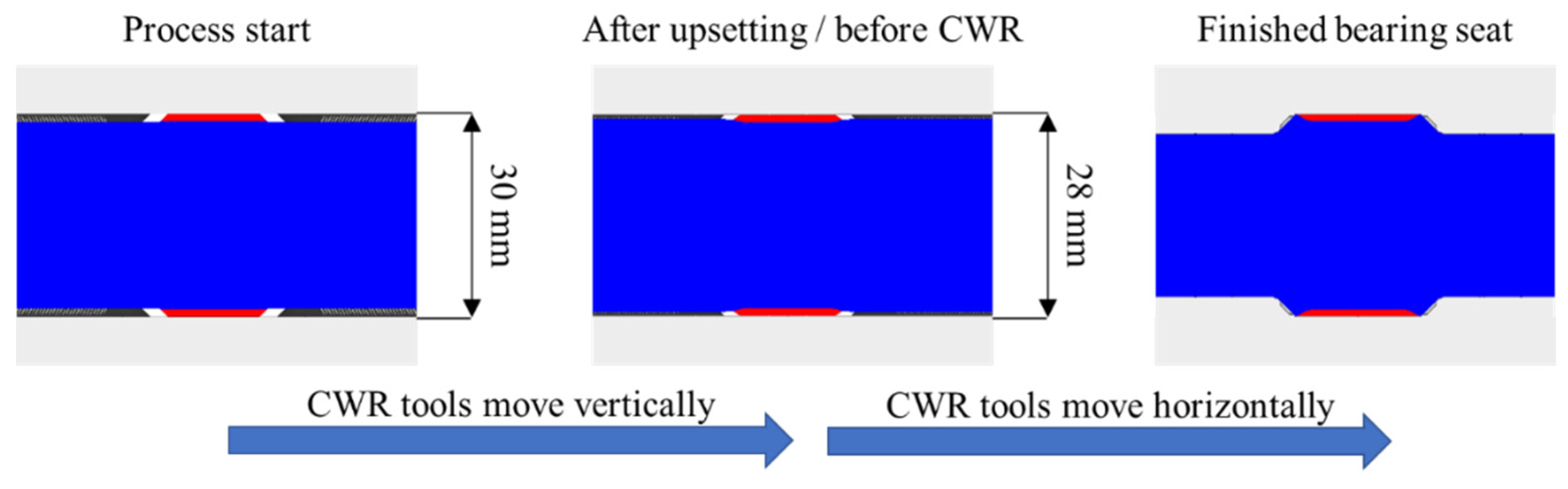
2.3. Cross-Wedge Rolling
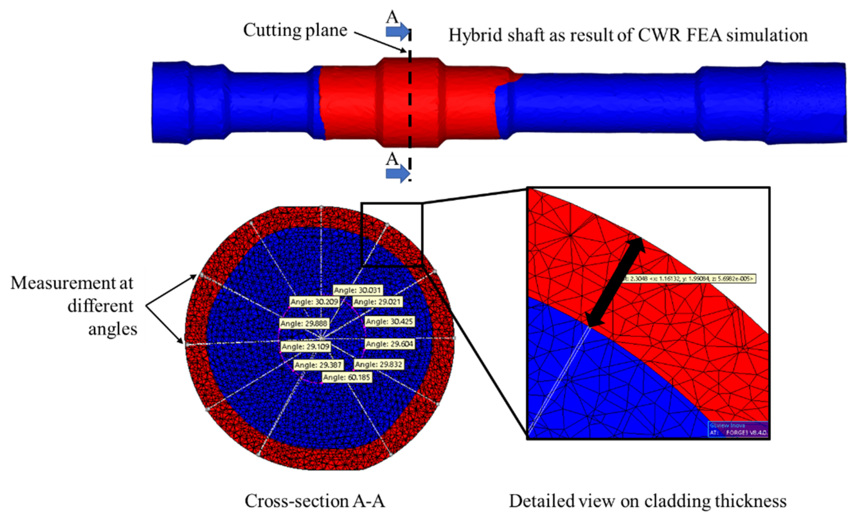
2.3.1. Cross-Wedge Rolling Simulation
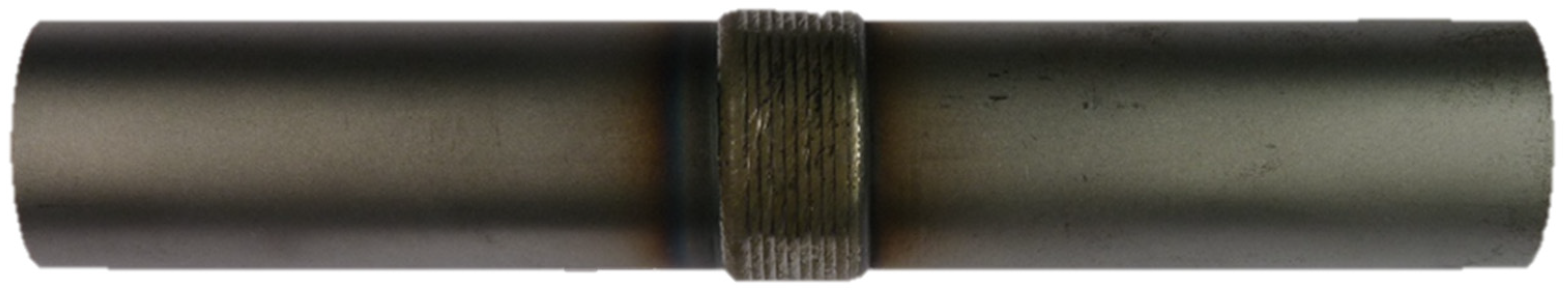
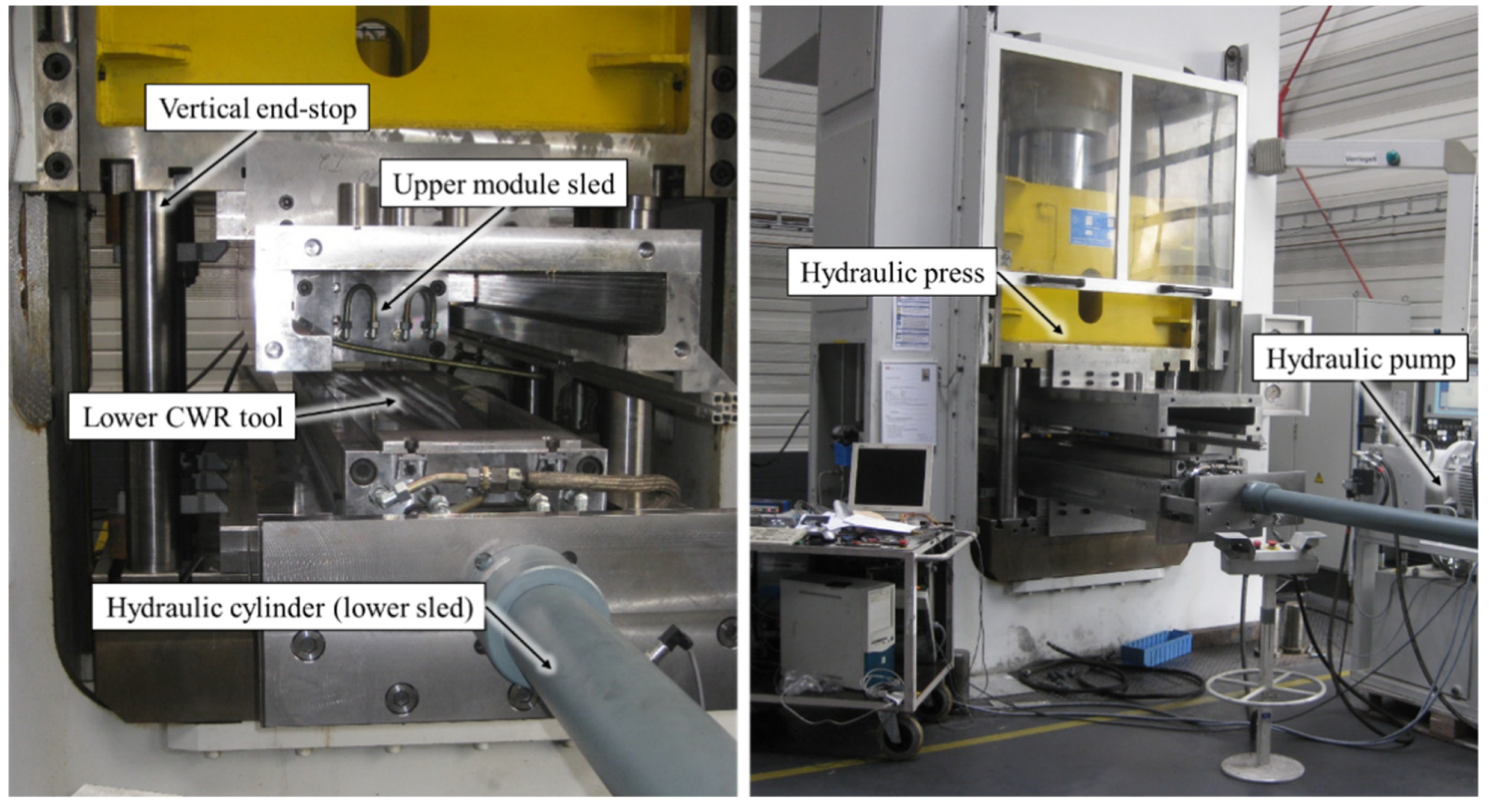
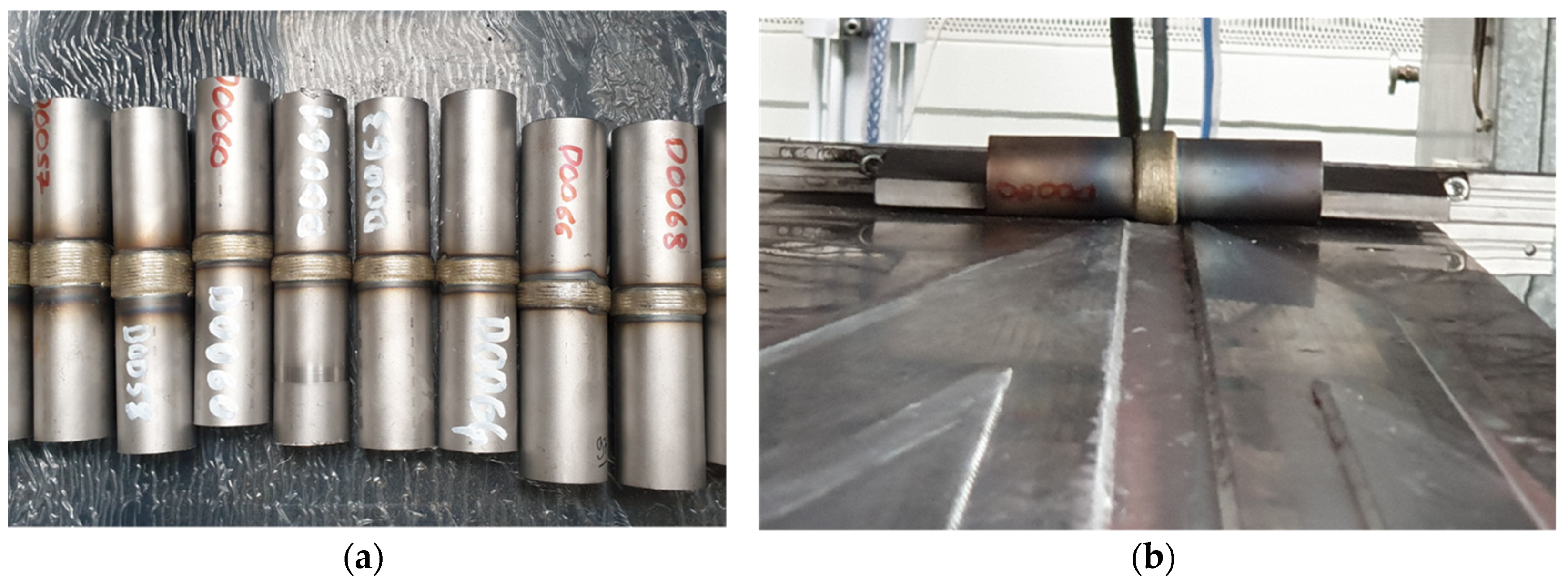
2.3.2. Cross-Wedge Rolling Experiment
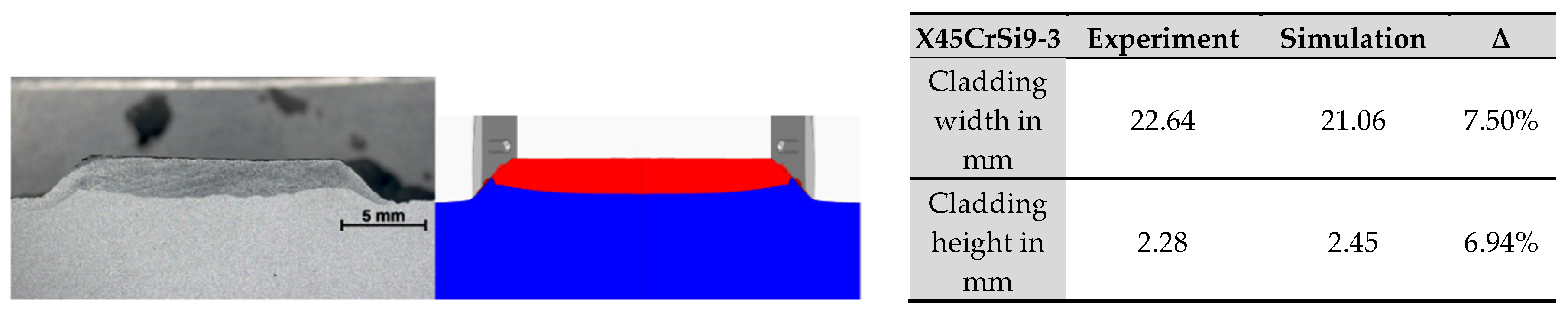
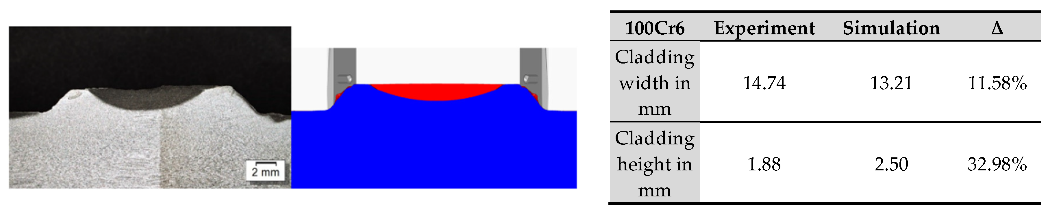
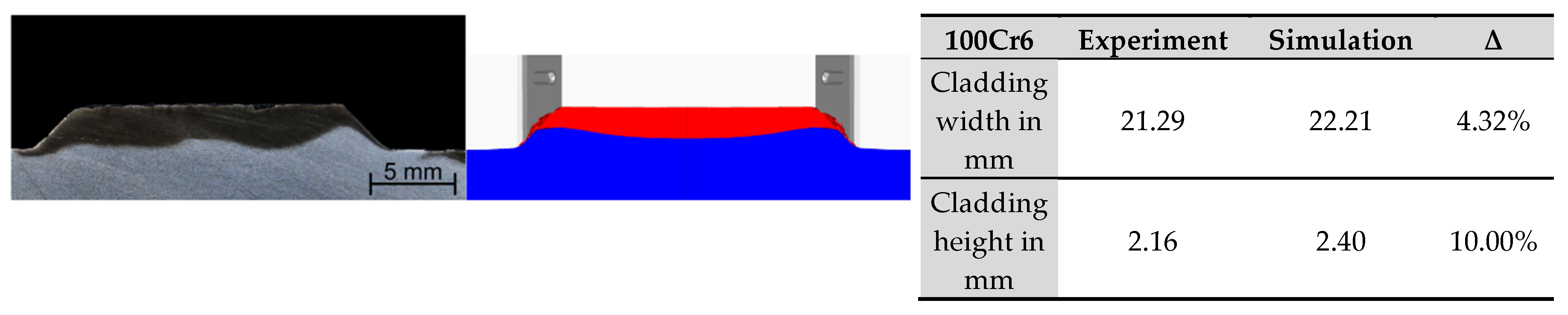
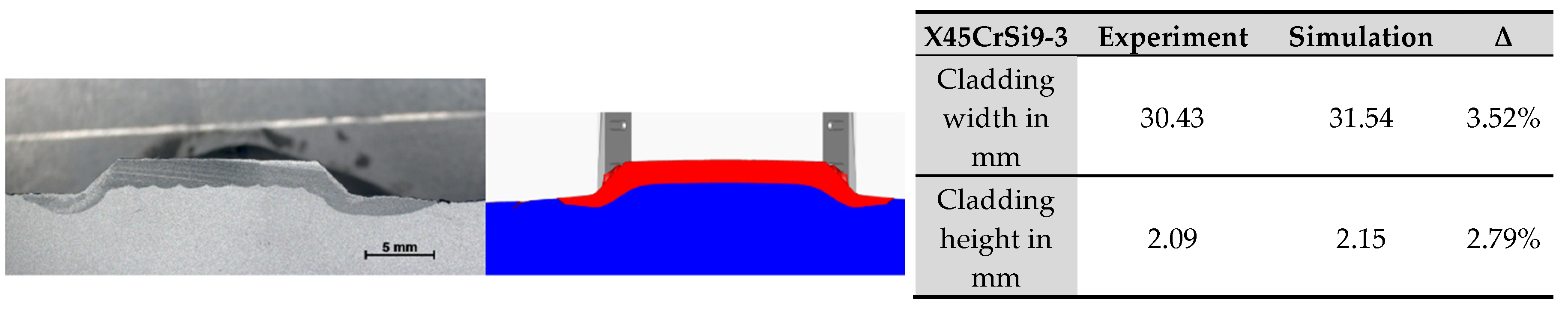
3. Results
4. Discussion and Conclusions
Author Contributions
Funding
Conflicts of Interest
References
- Mohamed, A.; Celik, T. An integrated knowledge-based system for alternative design and materials selection and cost estimating. Expert Syst. Appl. 1998, 14, 329–339. [Google Scholar] [CrossRef]
- Ljungberg, L.Y.; Edwards, K.L. Design, materials selection and marketing of successful products. Mater. Des. 2003, 24, 519–529. [Google Scholar] [CrossRef]
- Zhou, C.-C.; Yin, G.-F.; Hu, X.-B. Multi-objective optimization of material selection for sustainable products: Artificial neural networks and genetic algorithm approach. Mater. Des. 2009, 30, 1209–1215. [Google Scholar] [CrossRef]
- Sirisalee, P.; Ashby, M.F.; Parks, G.T.; Clarkson, P.J. Multi-criteria material selection in engineering design. Adv. Eng. Mater. 2004, 6, 84–92. [Google Scholar] [CrossRef]
- Bandyopadhyay, A.; Heer, B. Additive manufacturing of multi-material structures. Mater. Sci. Eng. R Rep. 2018, 129, 1–16. [Google Scholar] [CrossRef]
- Gouker, R.M.; Gupta, S.K.; Bruck, H.A.; Holzschuh, T. Manufacturing of multi-material compliant mechanisms using multi-material molding. Int. J. Adv. Manuf. Technol. 2006, 30, 1049–1075. [Google Scholar] [CrossRef] [Green Version]
- Merklein, M.; Johannes, M.; Lechner, M.; Kuppert, A. A review on tailored blanks—Production, applications and evaluation. J. Mater. Process. Technol. 2014, 214, 151–164. [Google Scholar] [CrossRef]
- Irving, B. Blank welding forces automakers to sit up and take notice. Weld. J. 1991, 70, 39–45. [Google Scholar]
- Saunders, F.I.; Wagoner, R.H. Forming of tailor-welded blanks. Metall. Mater. Trans. A 1996, 27, 2605–2616. [Google Scholar] [CrossRef] [Green Version]
- Behrens, B.-A.; Overmeyer, L.; Barroi, A.; Frischkorn, C.; Hermsdorf, J.; Kaierle, S.; Stonis, M.; Huskic, A. Basic study on the process combination of deposition welding and subsequent hot bulk forming. Prod. Eng. 2013, 7, 585–591. [Google Scholar] [CrossRef]
- Nguyen-Schäfer, H. Contact stresses in rolling bearings. In Computational Design of Rolling Bearings; Springer International Publishing: Cham, Switzerland, 2016. [Google Scholar] [CrossRef]
- Harris, T.A.; Barnsby, R.M. Life ratings for ball and roller bearings. Proc. Inst. Mech. Eng. Part J J. Eng. Tribol. 2001, 215, 577–595. [Google Scholar] [CrossRef]
- Hertz, H. Ueber die Berührung fester elastischer Körper. Journal für die Reine und Angewandte Mathematik 1882, 92, 156–171. [Google Scholar] [CrossRef]
- Belyaev, N.M. Local stresses in compression of elastic bodies. Inzhenernye Sooruzheniya i Stroitelnaya Mekhanika 1924, 27–108. [Google Scholar]
- Sadeghi, F.; Jalalahmadi, B.; Slack, T.S.; Raje, N.; Arakere, N.K. A Review of Rolling Contact Fatigue. ASME J. Tribol. 2009, 131, 041403. [Google Scholar] [CrossRef]
- Palmgren, A.; Lundberg, G. Dynamic Capacity of Rolling Bearings. Acta Polytech. Mech. Eng. Ser. 1947, 1, 7. [Google Scholar]
- Zwirlein, O.; Schlicht, H. Werkstoffanstrengung bei Walzbeanspruchung—Einfluss von Reibung und Eigenspannungen. Materialwissenschaft und Werkstofftechnik 1980, 11, 1–14. [Google Scholar] [CrossRef]
- Förster, R.; Förster, A. Einführung in die Fertigungstechnik; Springer Vieweg: Berlin, Germany, 2018; p. 130. [Google Scholar] [CrossRef]
- Schuler, V.; Twrdek, J. Praxiswissen Schweißtechnik: Werkstoffe, Prozesse, Fertigung, 6th ed.; Springer Vieweg: Wiesbaden, Germany, 2019; p. 268. ISBN 978-3-658-24266-4. [Google Scholar]
- Kottman, M.; Zhang, S.; McGuffin-Cawley, J.; Denney, P.; Narayanan, B.K. Laser Hot Wire Process: A Novel Process for Near-Net Shape Fabrication for High-Throughput. JOM J. Miner. Met. Mater. Soc. 2015, 67, 622–628. [Google Scholar] [CrossRef]
- Liu, S.; Liu, W.; Kovacevic, R. Experimental investigation of laser hot-wire cladding. Proc. Inst. Mech. Eng. B J. Eng. 2017, 231, 1007–1020. [Google Scholar] [CrossRef]
- Nowotny, S.; Brueckner, F.; Thieme, S.; Leyens, C.; Beyer, E. High-performance laser cladding with combined energy sources. J. Laser Appl. 2015, 27, 1–7. [Google Scholar] [CrossRef]
- Lostado Lorza, R.; Escribano García, R.; Fernandez Martinez, R.; Martínez Calvo, M.Á. Using Genetic Algorithms with Multi-Objective Optimization to Adjust Finite Element Models of Welded Joints. Metals 2018, 8, 230. [Google Scholar] [CrossRef] [Green Version]
- Blohm, T.; Nothdurft, S.; Mildebrath, M.; Ohrdes, H.; Richter, J.; Stonis, M.; Langner, J.; Springer, A.; Kaierle, S.; Hassel, T.; et al. Investigation of the joining zone of laser welded and cross wedge rolled hybrid parts. Int. J. Mater. Form. 2018, 11, 829–837. [Google Scholar] [CrossRef]
- Coors, T.; Hwang, J.-I.; Pape, F.; Poll, G. Theoretical investigations on the fatigue behavior of a tailored forming steel-aluminium bearing component. AIP Conf. Proc. 2019, 2113, 040020. [Google Scholar] [CrossRef]
- Coors, T.; Pape, F.; Poll, G. Bearing Fatigue Life of a Multi-Material Shaft with an Integrated Raceway. Bear. World J. 2018, 3, 23–30. [Google Scholar]
- Matthes, K.; Schneider, W. Schweißtechnik—Schweißen von Metallischen Konstruktionswerkstoffen, 6th ed.; Hanser Verlag: München, Germany, 2016; pp. 33–34. ISBN 978-3446405684. [Google Scholar]
- Dilthey, U. Schweißtechnische Fertigungsverfahren 2—Verhalten der Werkstoffe beim Schweißen, 3rd ed.; Springer: Berlin, Germany, 2005; p. 130. ISBN 978-3-540-27402-5. [Google Scholar]
- Lammers, M.; Budde, L.; Barroi, A.; Hermsdorf, J.; Kaierle, S. Entwicklung von Laser-Systemkomponenten optimiert für die additive Serienfertigung mittels SLM. In Konstruktion für die Additive Fertigung, 1st ed.; Lachmayer, R., Lippert, R.B., Kaierle, S., Eds.; Springer Vieweg: Berlin/Heidelberg, Germany, 2020; pp. 21–35. [Google Scholar] [CrossRef]
- Pajukoski, H.; Näkki, J.; Thieme, S.; Tuominen, J.; Nowotny, S.; Vuoristo, P. High performance corrosion resistant coatings by novel coaxial cold- and hot-wire laser cladding methods. J. Laser Appl. 2016, 28, 012011. [Google Scholar] [CrossRef]
- Pater, Z. Cross-Wedge Rolling. In Comprehensive Materials Processing 13 Volume Set, 1st ed.; Hashmi, S., Batalha, G.F., van Tyne, C.J., Yilbas, B., Eds.; Elsevier: Amsterdam, The Netherlands, 2014; Volume 3. [Google Scholar] [CrossRef]
- Kruse, J.; Jagodzinski, A.; Langner, J.; Stonis, M.; Behrens, B.-A. Investigation of the joining zone displacement of cross-wedge rolled serially arranged hybrid parts. Int. J. Mater. Form. 2019, 13, 577–589. [Google Scholar] [CrossRef]
- Pater, Z.; Tomczak, J.; Bulzak, T. New forming possibilities in cross wedge rolling processes. Arch. Civ. Mech. Eng. 2018, 18, 149–161. [Google Scholar] [CrossRef]
- Pater, Z.; Tomczak, J.; Bulzak, T.; Wójcik, Ł.; Lis, K. Rotary compression in tool cavity—A new ductile fracture calibration test. Int. J. Adv. Manuf. Technol. 2020, 106, 4437–4449. [Google Scholar] [CrossRef] [Green Version]
- Transvalor, S. A Reference Documentation; FORGE® NxT 3.0; Transvalor: Biot, France, 2019. [Google Scholar]
- Hensel, A.; Spittel, T. Kraft- und Arbeitsbedarf Bildsamer Formgebungsverfahren, 1st ed.; Deutscher Verlag für Grundstoffindustrie: Leipzig, Germany, 1978. [Google Scholar]
- Jagodzinski, A.; Kruse, J.; Barroi, A.; Mildebrath, M.; Langner, J.; Stonis, M.; Lammers, M.; Hermsdorf, J.; Hassel, T.; Behrens, B.-A.; et al. Investigation of the Prediction Accuracy of a Finite Element Analysis Model for the Coating Thickness in Cross-Wedge Rolled Coaxial Hybrid Parts. Materials 2019, 12, 2969. [Google Scholar] [CrossRef] [Green Version]


| Element | C | Si | Mn | P | S | Cr | Ni | |
|---|---|---|---|---|---|---|---|---|
| Material | ||||||||
| C22.8 | 0.17–0.24 | <0.40 | 0.40–0.70 | <0.045 | <0.045 | <0.40 | - | |
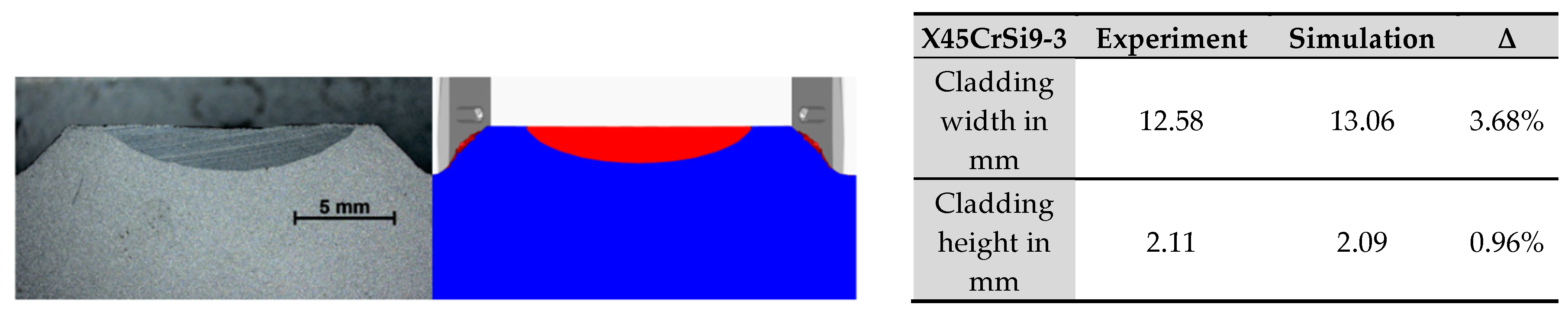
| X45CrSi9-3 | 0.4–0.5 | 2.7–3.3 | ≤0.6 | ≤0.004 | ≤0.03 | 8.0–10.0 | ≤0.5 | |
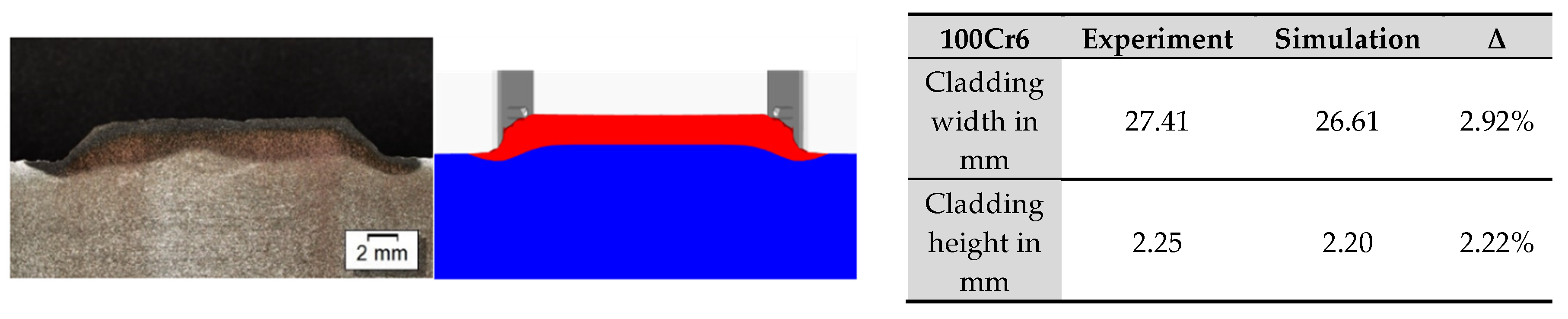
| 100Cr6 | 0.93–1.05 | 0.15–0.35 | 0.25–0.45 | ≤0.025 | ≤0.015 | 1.35–1.60 | - | |
| Parameter | LMD-W 1 |
|---|---|
| Welding speed | 1200 mm/min |
| Current | 110 A |
| Wire feed rate | 2.8 m/min |
| Laser power | 2.3 kW |
| Shielding gas flow | 8 L/min |
| Wire diameter | 1.0 mm |
| Parameter | Value |
|---|---|
| Shielding gas flow | 10 L/min |
| Plasma gas flow | 1.5 L/min |
| Transport gas flow | 6 L/min |
| Welding speed | 0.06 m /min |
| Length of the welding seam | 30 mm |
| Current | 120–100 A |
| Voltage | 27–25 V (depends on current) |
| Powder material | 100Cr6 |
| Grid size of powder particles | 0.06–0.2 mm |
| Deposition rate | 0.9 kg/h |
| Case ID | Thermal Expansion Calculation 1 | Tool Behavior | Thermal Expansion due to Initial Heating 1 | Estimated Normalized Calculation Time |
|---|---|---|---|---|
| #1 | No | rigid | No | 100% |
| #2 | Yes | rigid | Yes | 182% |
| #3 | Yes | deformable | Yes | 449% |
| Simulation Result | Setup | Cross Section Surface of: | Max. Coating Thickness | Min. Coating Thickness | Avg. Coating Thickness | |
|---|---|---|---|---|---|---|
| Cladding | Base Cylinder | |||||
 | #1: No thermal expansion; Rigid tools | 644.082 mm2 | 452.646 mm2 | 2.263 mm | 2.854 mm | 2.439 mm |
 | #2: Thermal expansion; Rigid tools | 644.912 mm2 | 455.057 mm2 | 2.101 mm | 2.830 mm | 2.426 mm |
| Δ to Setup #1 | 0.10% | 0.50% | 7.20% | 0.80% | 0.50% | |
 | #3: Thermal expansion; Deformable tools | 643.981 mm2 | 430.330 mm2 | 2.131 mm | 2.872 mm | 2.381 mm |
| Δ to Setup #1 | 0.00% | 5.20% | 6.20% | 0.60% | 2.40% | |
| Material | Work Piece Geometry | Tool Velocity | Work Piece Temperature |
|---|---|---|---|
| Base cylinder: C22.8 | Ø 27 or 29 mm | 240 mm/s | 1250 °C |
| Cladding: X45CrSi9-3 or 100Cr6 | 8 or 15 mm width; 1.2; 2.4; or 2.5 mm height |
© 2020 by the authors. Licensee MDPI, Basel, Switzerland. This article is an open access article distributed under the terms and conditions of the Creative Commons Attribution (CC BY) license (http://creativecommons.org/licenses/by/4.0/).
Share and Cite
Kruse, J.; Mildebrath, M.; Budde, L.; Coors, T.; Faqiri, M.Y.; Barroi, A.; Stonis, M.; Hassel, T.; Pape, F.; Lammers, M.; et al. Numerical Simulation and Experimental Validation of the Cladding Material Distribution of Hybrid Semi-Finished Products Produced by Deposition Welding and Cross-Wedge Rolling. Metals 2020, 10, 1336. https://doi.org/10.3390/met10101336
Kruse J, Mildebrath M, Budde L, Coors T, Faqiri MY, Barroi A, Stonis M, Hassel T, Pape F, Lammers M, et al. Numerical Simulation and Experimental Validation of the Cladding Material Distribution of Hybrid Semi-Finished Products Produced by Deposition Welding and Cross-Wedge Rolling. Metals. 2020; 10(10):1336. https://doi.org/10.3390/met10101336
Chicago/Turabian StyleKruse, Jens, Maximilian Mildebrath, Laura Budde, Timm Coors, Mohamad Yusuf Faqiri, Alexander Barroi, Malte Stonis, Thomas Hassel, Florian Pape, Marius Lammers, and et al. 2020. "Numerical Simulation and Experimental Validation of the Cladding Material Distribution of Hybrid Semi-Finished Products Produced by Deposition Welding and Cross-Wedge Rolling" Metals 10, no. 10: 1336. https://doi.org/10.3390/met10101336
APA StyleKruse, J., Mildebrath, M., Budde, L., Coors, T., Faqiri, M. Y., Barroi, A., Stonis, M., Hassel, T., Pape, F., Lammers, M., Hermsdorf, J., Kaierle, S., Overmeyer, L., & Poll, G. (2020). Numerical Simulation and Experimental Validation of the Cladding Material Distribution of Hybrid Semi-Finished Products Produced by Deposition Welding and Cross-Wedge Rolling. Metals, 10(10), 1336. https://doi.org/10.3390/met10101336