Applying Membrane Mode Enhanced Cohesive Zone Elements on Tailored Forming Components


Abstract
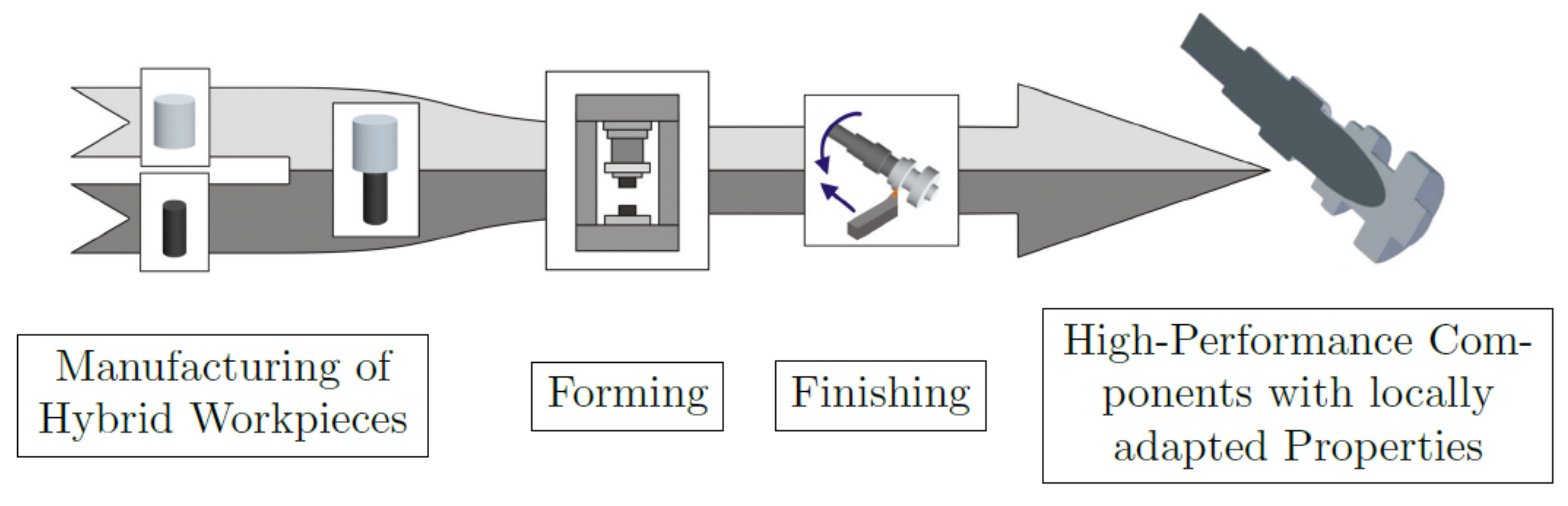
1. Introduction
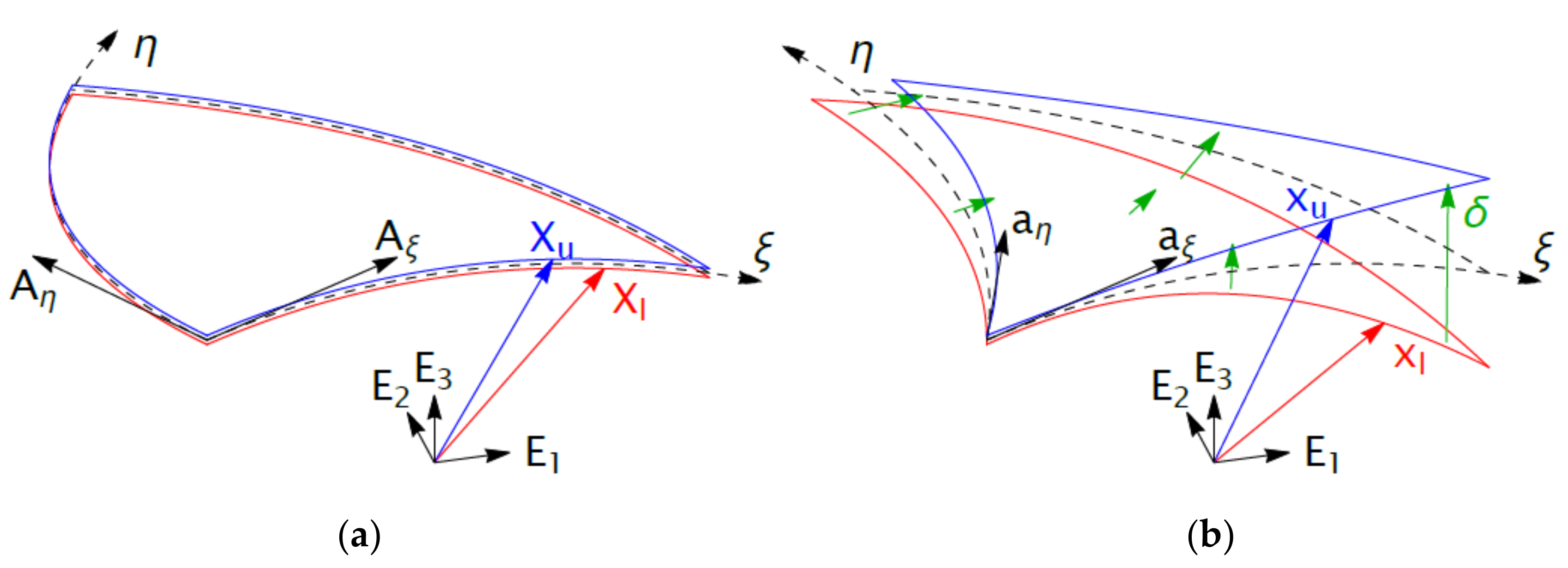
2. Membrane Mode Enhanced Cohesive Zone Elements
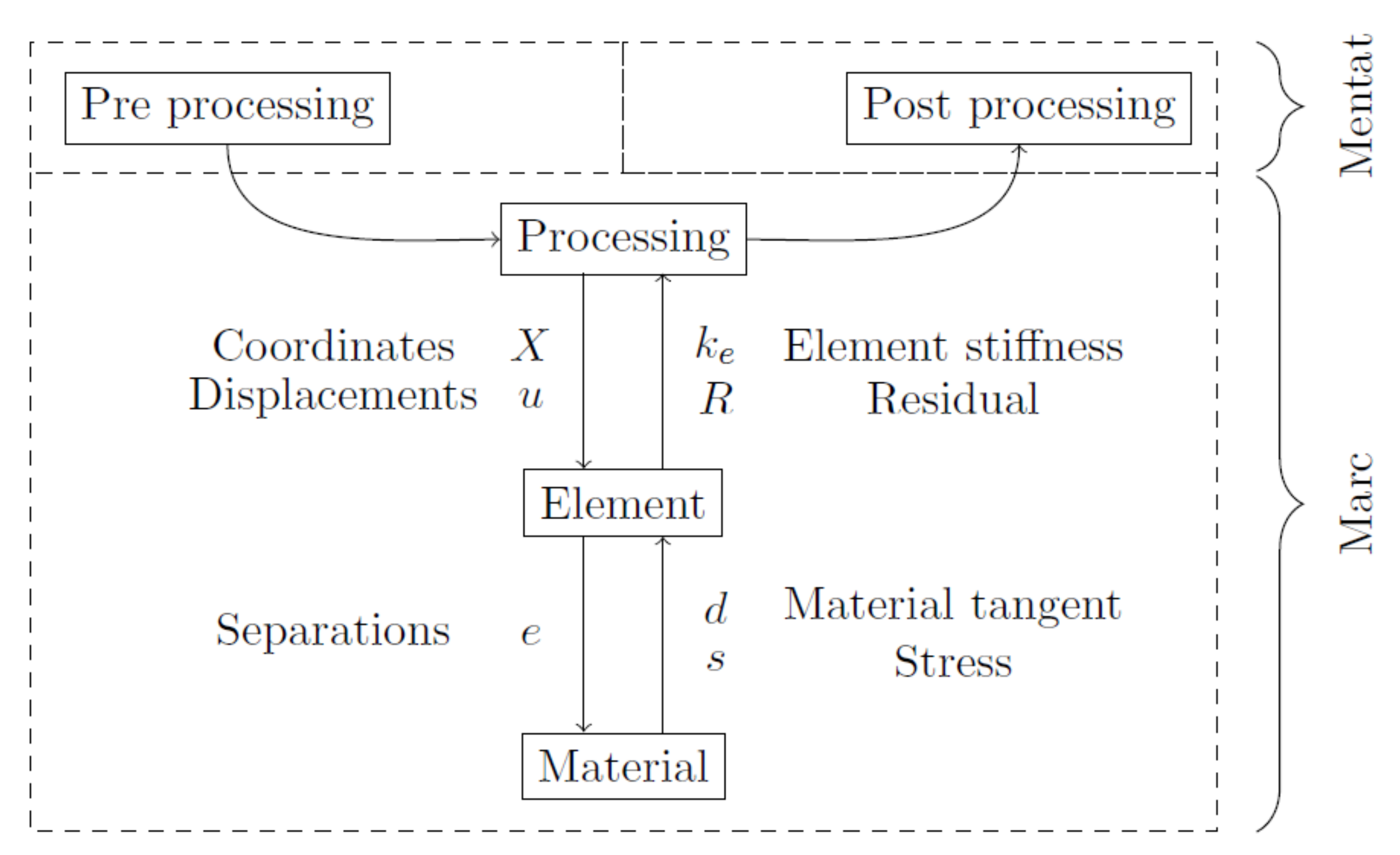
3. Cohesive Modelling in MSC Marc
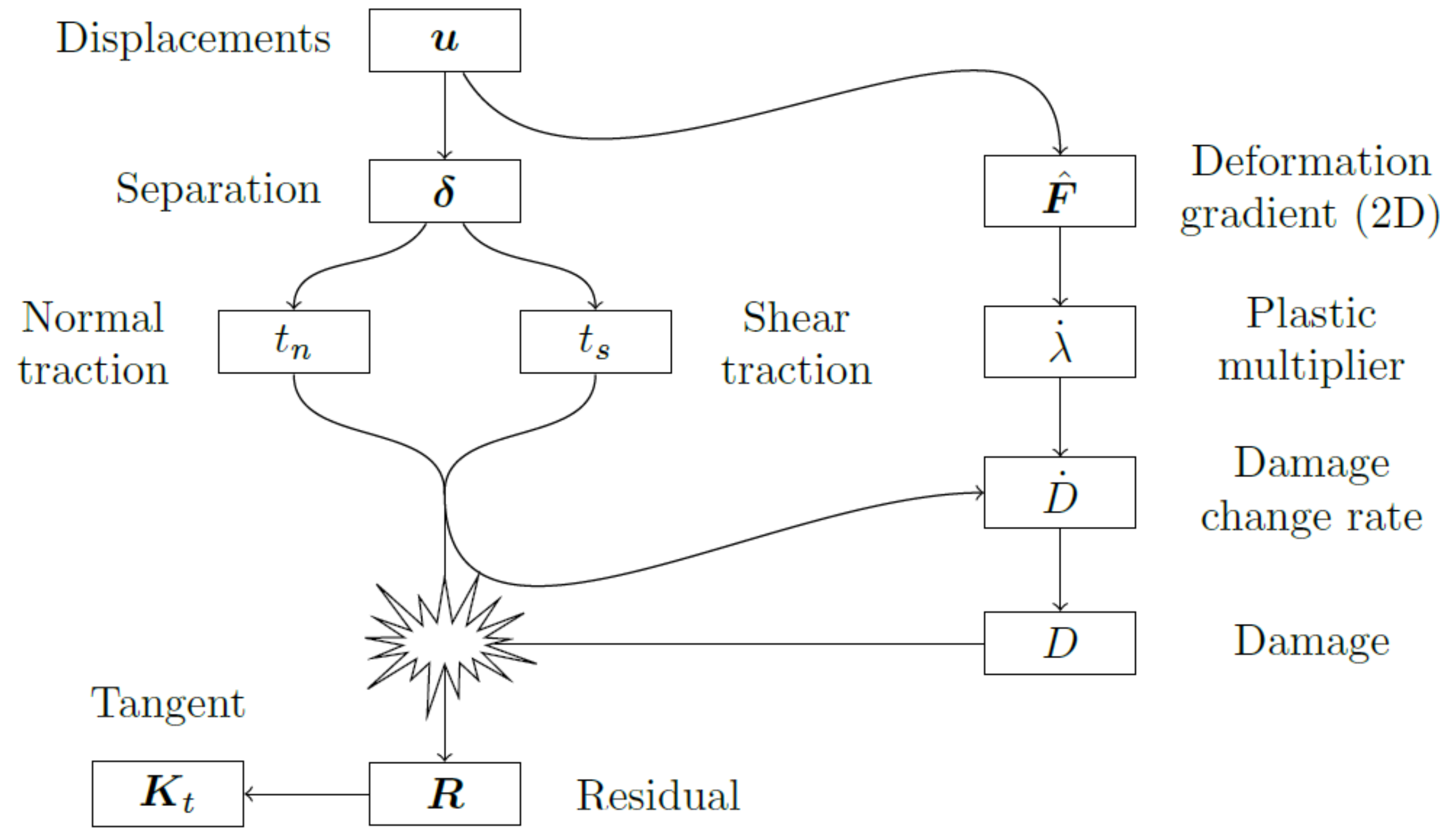
4. Membrane Mode Enhanced Cohesive Zone Element Technology as a Material Subroutine
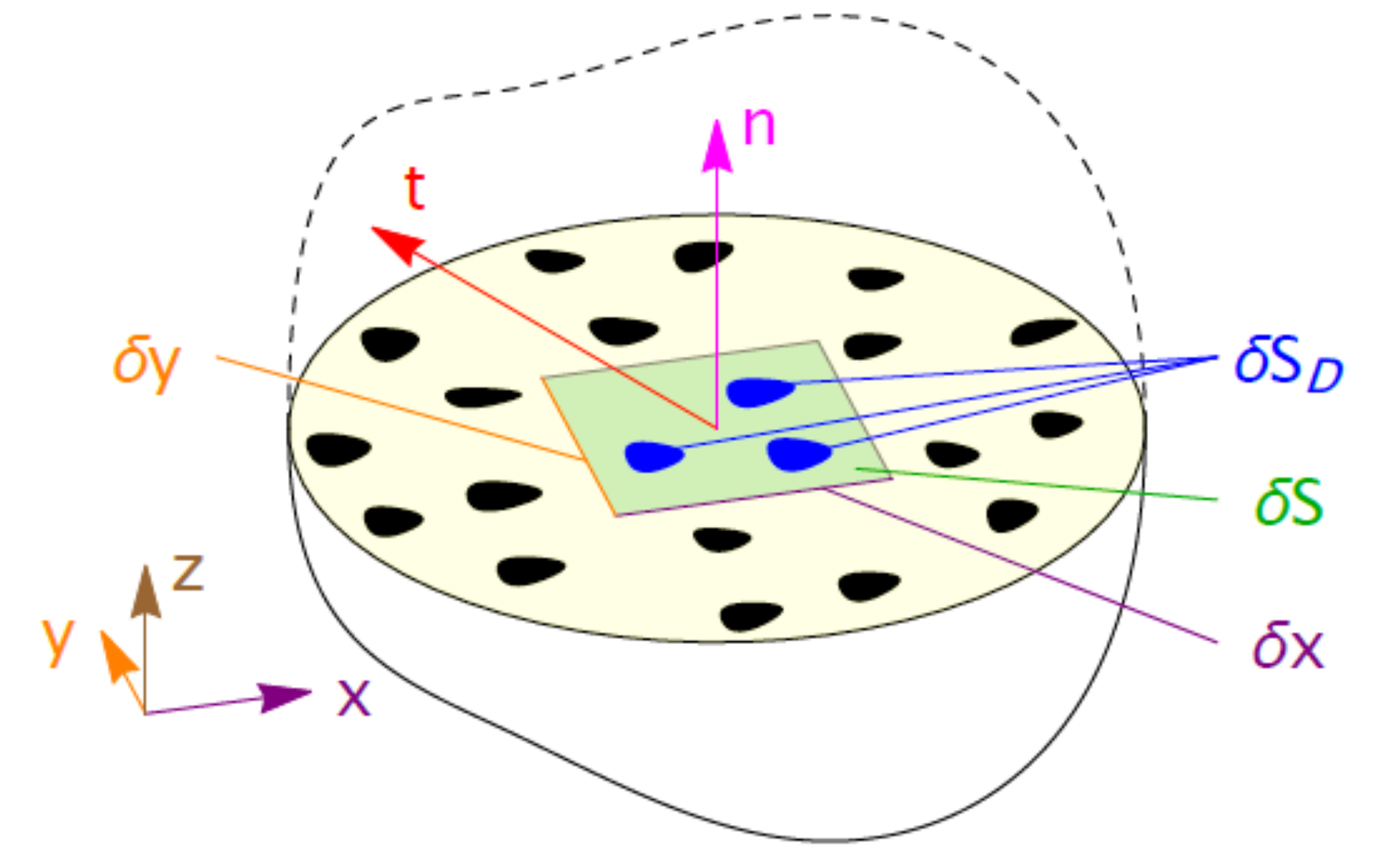
4.1. Gathering Information about the Membrane Deformation
4.2. Returning Stress and Material Tangent
4.3. Thermal and Mechanical Parameters
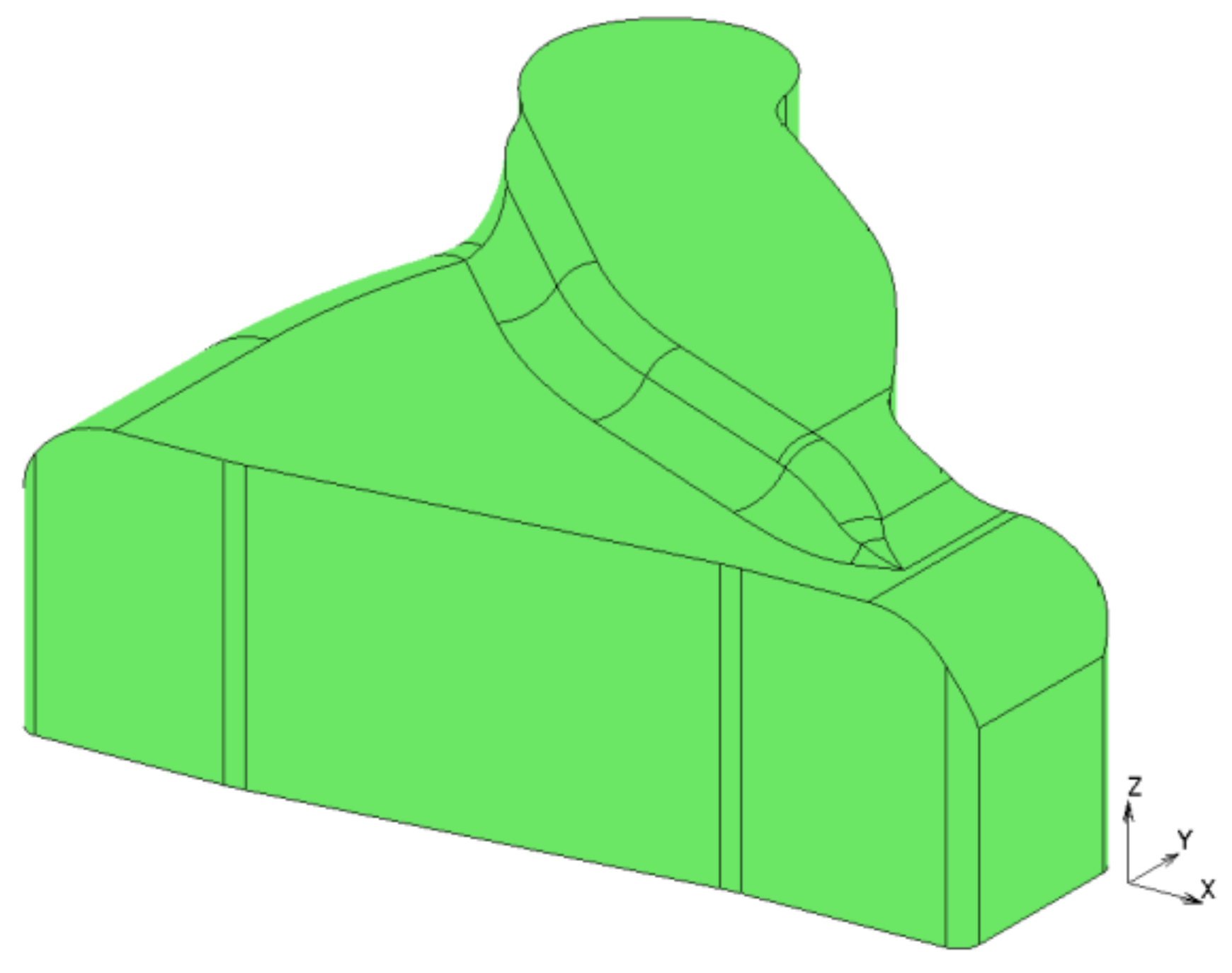
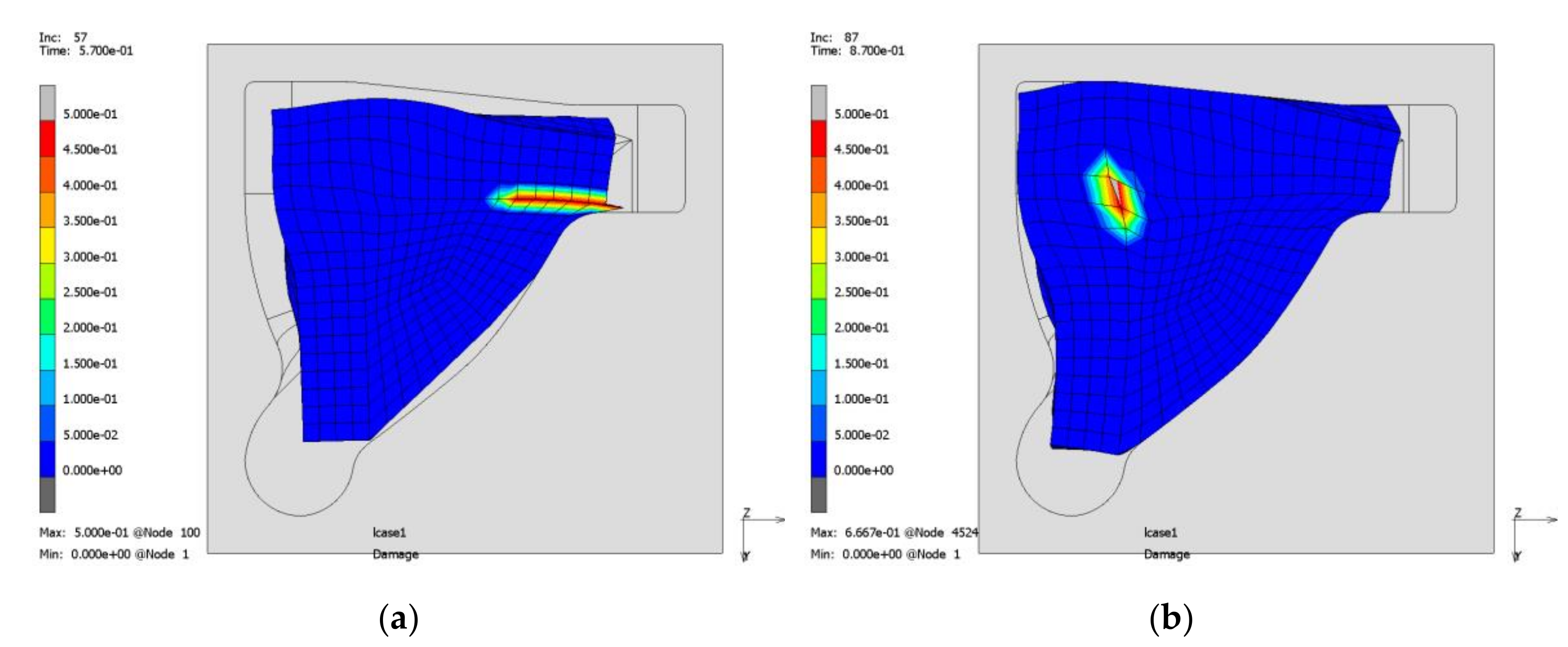
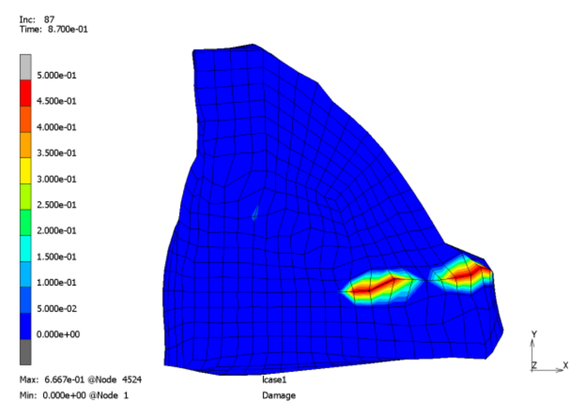
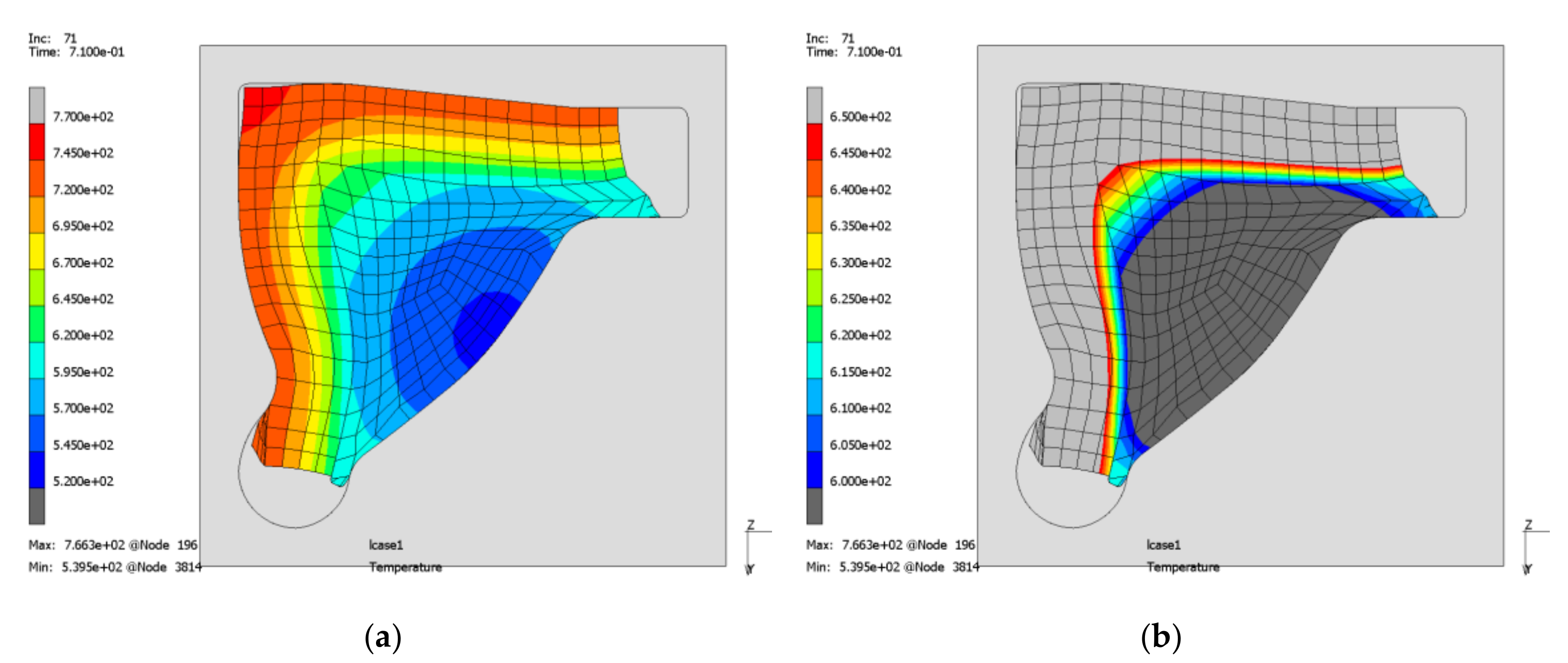
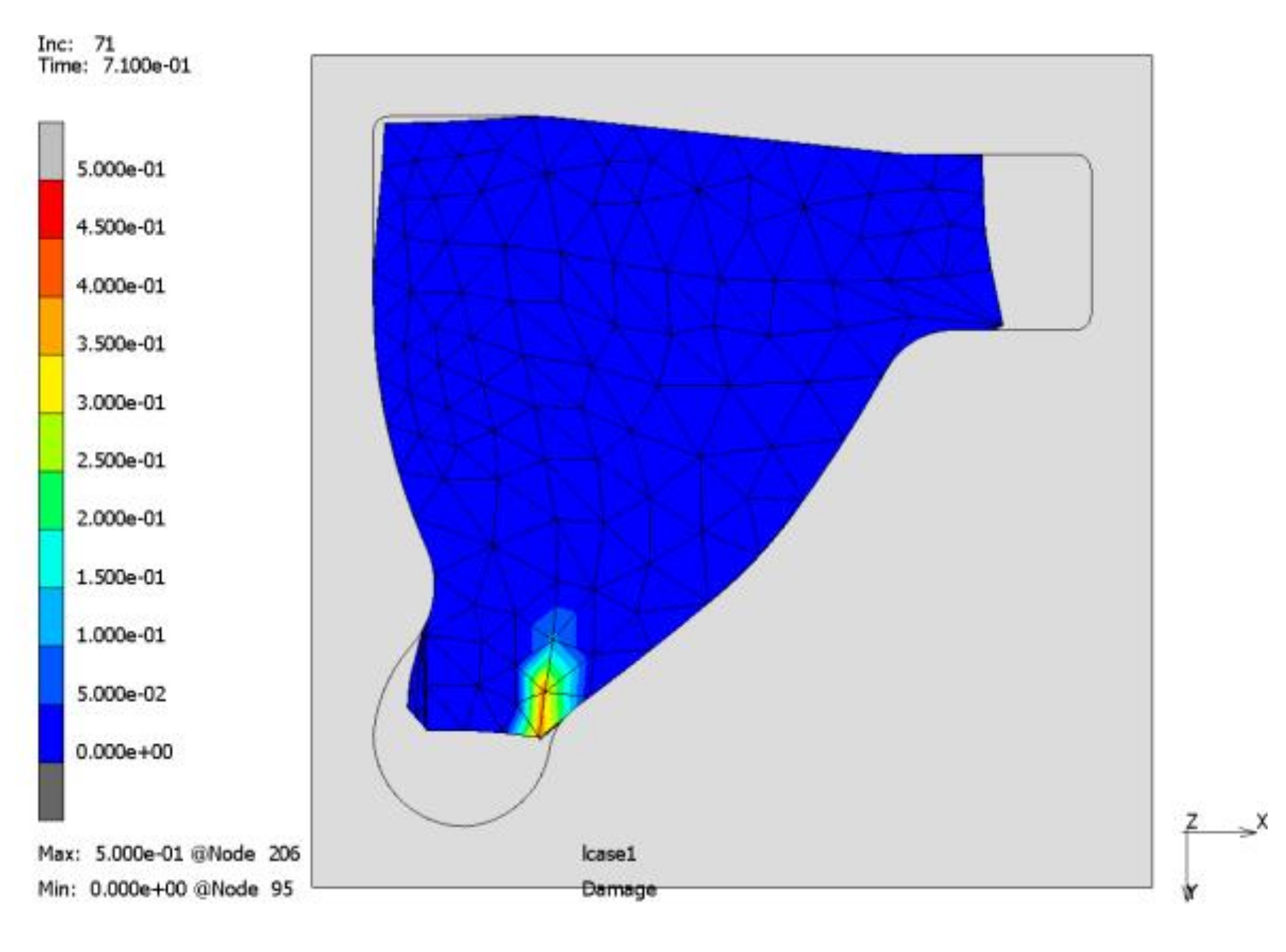
5. Simulation of a Transverse Link
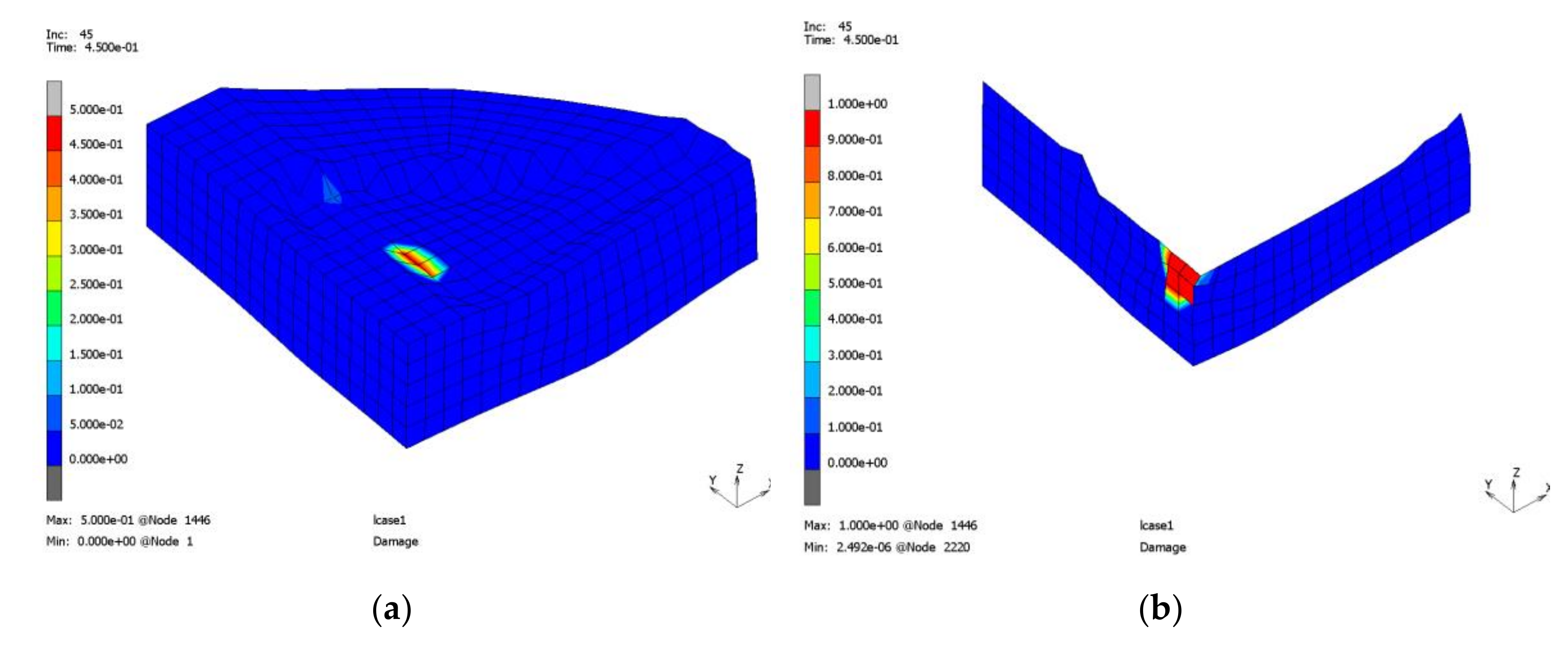
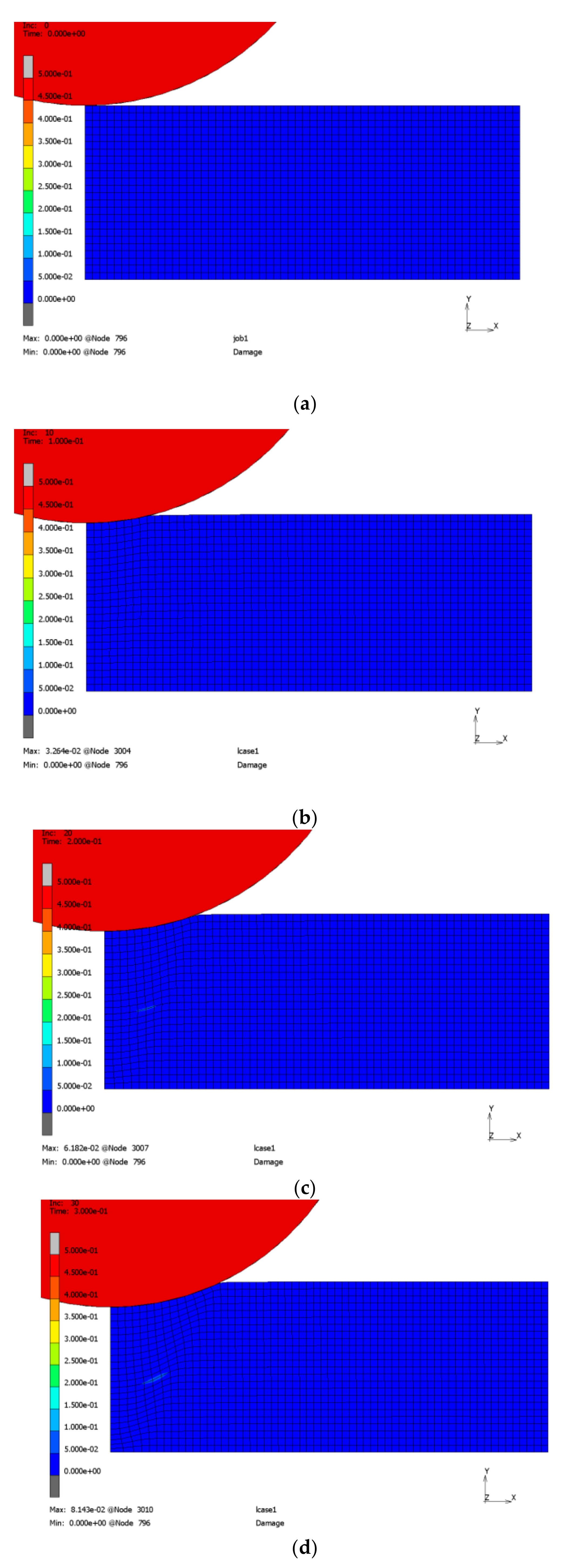
6. Indentation Test
7. Conclusions
- (1)
- The intended geometry contains severe deformation affecting the joining zone.
- (2)
- A more similar geometry of the raw component and the formed component would reduce the probability of failure initiation here.
- (3)
- The starting position in the form significantly influences the process and should be fixed.
- (4)
- A closed die process with burr prevention should be considered to prevent zones with very large deformation where a crack initiation might be triggered.
Author Contributions
Funding
Conflicts of Interest
References
- Geplanter Sonderforschungsbereich 1153—Prozesskette zur Herstellung hybrider Hochleistungsbauteile durch Tailored Forming—Einrichtungsantrag. 2014.
- Herbst, S.; Dovletoglou, C.N.; Nuernberger, F. Method for Semi-Automated Measurement and Statistical Evaluation of Iron Aluminum Intermetallic Compound Layer Thickness and Morphology. Met. Microstruct. Anal. 2017, 6, 367–374. [Google Scholar] [CrossRef]
- Behrens, B.A.; Bonhage, M.; Bohr, D.; Duran, D. Simulation Assisted Process Development for Tailored Forming. Mater. Sci. Forum 2019, 949, 101–111. [Google Scholar] [CrossRef]
- Töller, F.; Löhnert, S.; Wriggers, P. Bulk material models in Cohesive Zone Elements for simulation of joining zones. Finite Elements Anal. Des. 2019, 164, 42–54. [Google Scholar] [CrossRef]
- Töller, F.; Löhnert, S.; Wriggers, P. Membrane mode enhanced cohesive zone elements. Eng. Comput. 2020. Unpublished work. [Google Scholar]
- Lemaitre, J.; Desmorat, R. Engineering Damage Mechanics: Ductile, Creep, Fatigue and Brittle Failures; Springer Science & Business Media: Berlin/Heidelberg, Germany, 2005. [Google Scholar]
- MSC.Software Corporation. MSC.Marc Volume B: Element Library. version 2019.
- MSC.Software Corporation. MSC.Marc Volume D: User Subroutines and Special Routines. version 2019.
- Töller, F.; Löhnert, S.; Wriggers, P. Thermo-mechanical coupling for internal thickness extrapolation elements. In Proceedings of the 8th GACM Colloquium on Computational Mechanics: For Young Scientists from Academia and Industry, Kassel, Germany, 28–30 August 2019; Gleim, T., Lange, S., Eds.; Kassel University Press GmbH: Kassel, Germany, 2019. [Google Scholar]
- Behrens, B.-A.; Chugreev, A.; Selinski, M.; Matthias, T. Joining zone shape optimisation for hybrid components made of aluminium-steel by geometrically adapted joining surfaces in the friction welding process. In Proceedings of the AIP Conference Proceedings; AIP Publishing: College Park, MD, USA, 2019; Volume 2113, p. 040027. [Google Scholar]


| Number of Elements in Horizontal Direction | Failure in Increment | Failure Position from Left Corner |
|---|---|---|
| 10 | 59 | 0.21 mm |
| 20 | 47 | 1.40 mm |
| 30 | 43 | 0.93 mm |
| 40 | 40 | 1.20 mm |
| 50 | 39 | 1.16 mm |
| 60 | 37 | 1.13 mm |
© 2020 by the authors. Licensee MDPI, Basel, Switzerland. This article is an open access article distributed under the terms and conditions of the Creative Commons Attribution (CC BY) license (http://creativecommons.org/licenses/by/4.0/).
Share and Cite
Töller, F.; Löhnert, S.; Wriggers, P. Applying Membrane Mode Enhanced Cohesive Zone Elements on Tailored Forming Components. Metals 2020, 10, 1333. https://doi.org/10.3390/met10101333
Töller F, Löhnert S, Wriggers P. Applying Membrane Mode Enhanced Cohesive Zone Elements on Tailored Forming Components. Metals. 2020; 10(10):1333. https://doi.org/10.3390/met10101333
Chicago/Turabian StyleTöller, Felix, Stefan Löhnert, and Peter Wriggers. 2020. "Applying Membrane Mode Enhanced Cohesive Zone Elements on Tailored Forming Components" Metals 10, no. 10: 1333. https://doi.org/10.3390/met10101333
APA StyleTöller, F., Löhnert, S., & Wriggers, P. (2020). Applying Membrane Mode Enhanced Cohesive Zone Elements on Tailored Forming Components. Metals, 10(10), 1333. https://doi.org/10.3390/met10101333