Applying Membrane Mode Enhanced Cohesive Zone Elements on Tailored Forming Components


Abstract
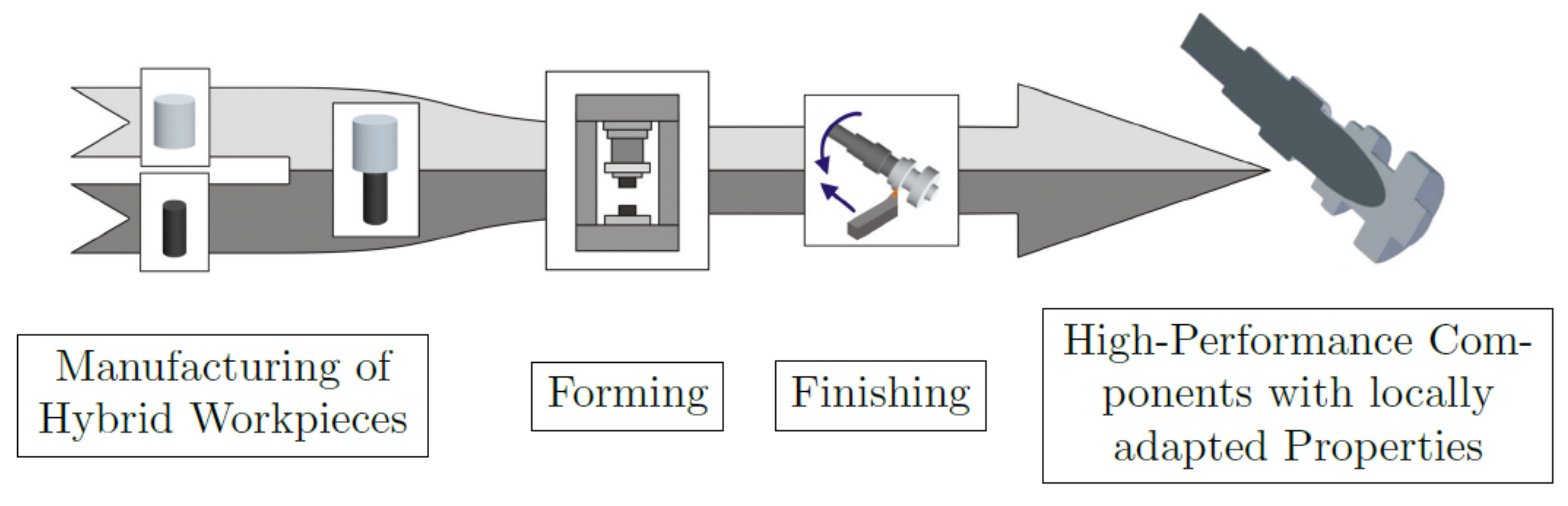
:1. Introduction
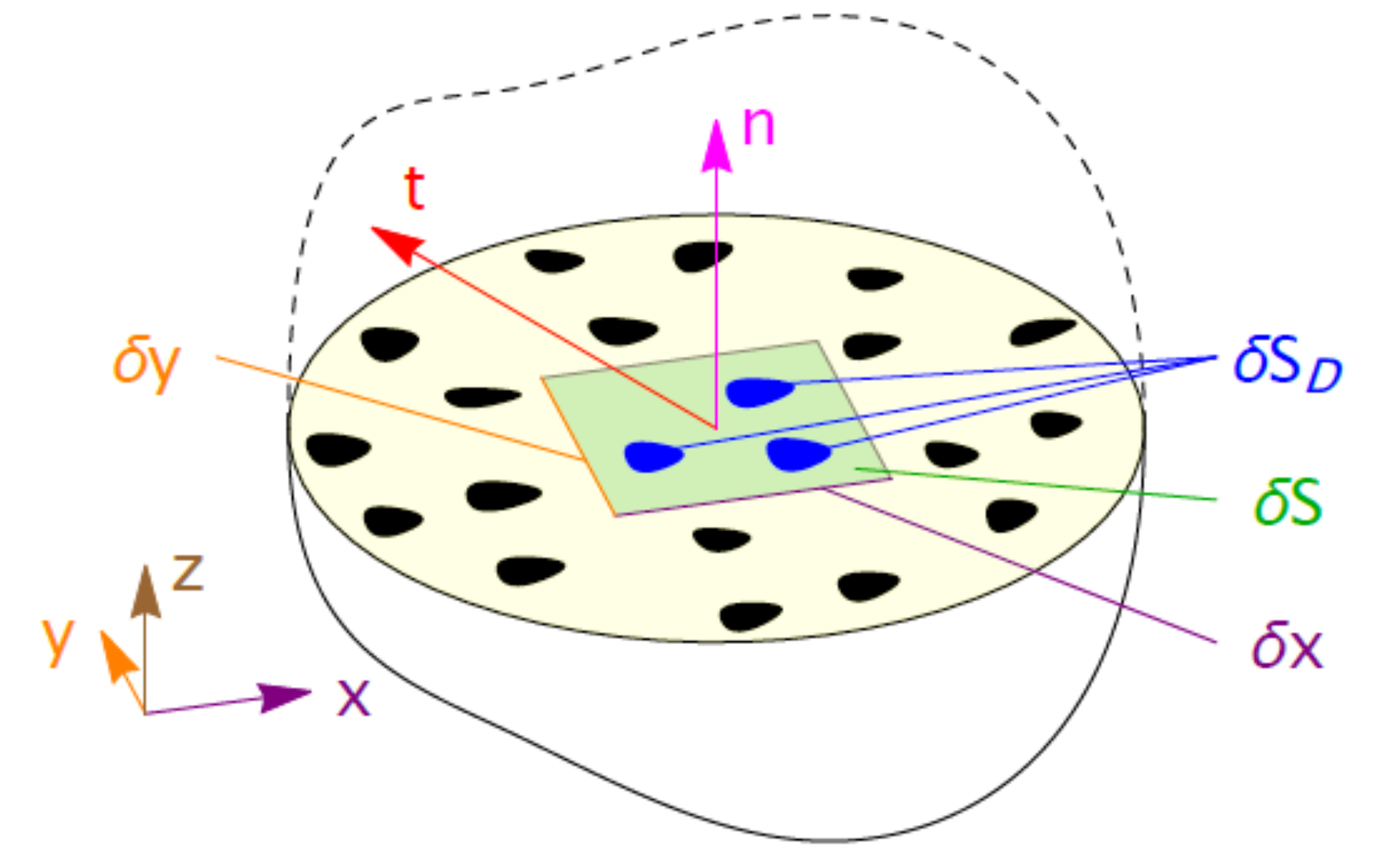
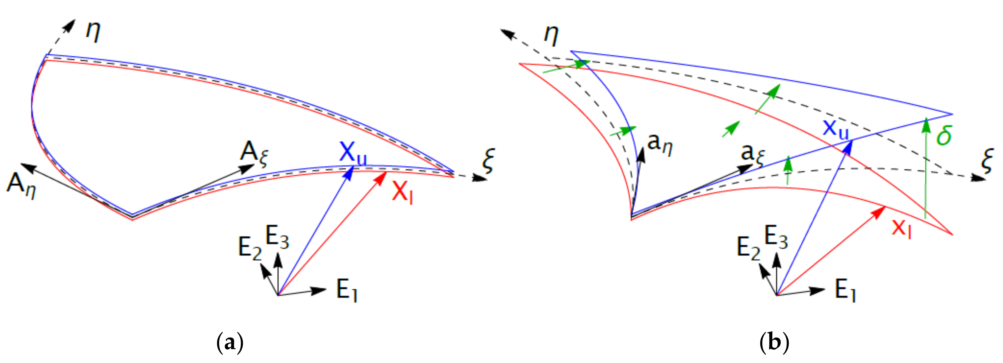
2. Membrane Mode Enhanced Cohesive Zone Elements
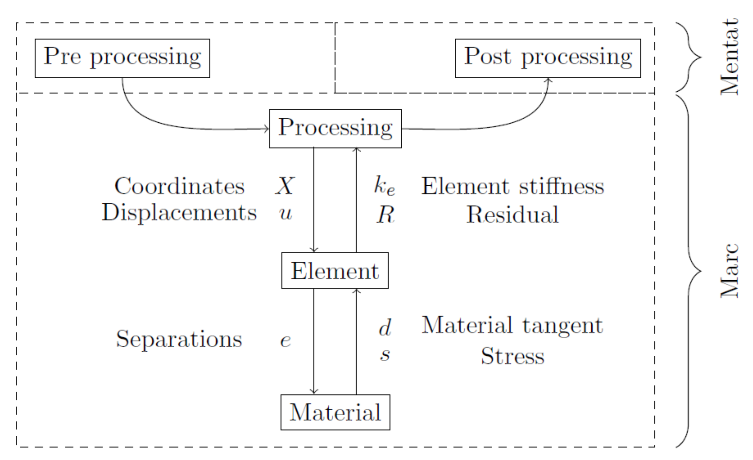
3. Cohesive Modelling in MSC Marc
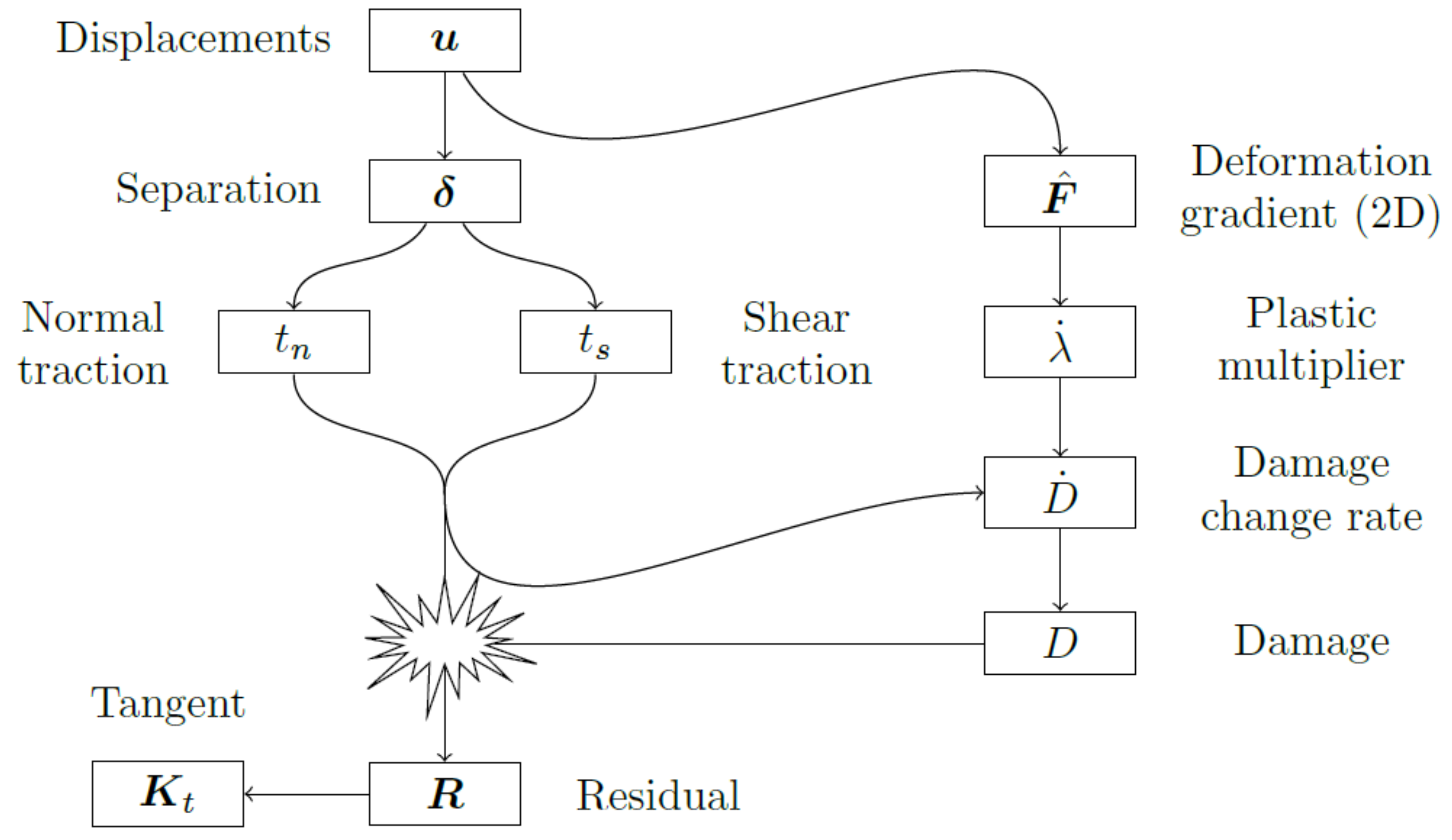
4. Membrane Mode Enhanced Cohesive Zone Element Technology as a Material Subroutine
4.1. Gathering Information about the Membrane Deformation
4.2. Returning Stress and Material Tangent
4.3. Thermal and Mechanical Parameters
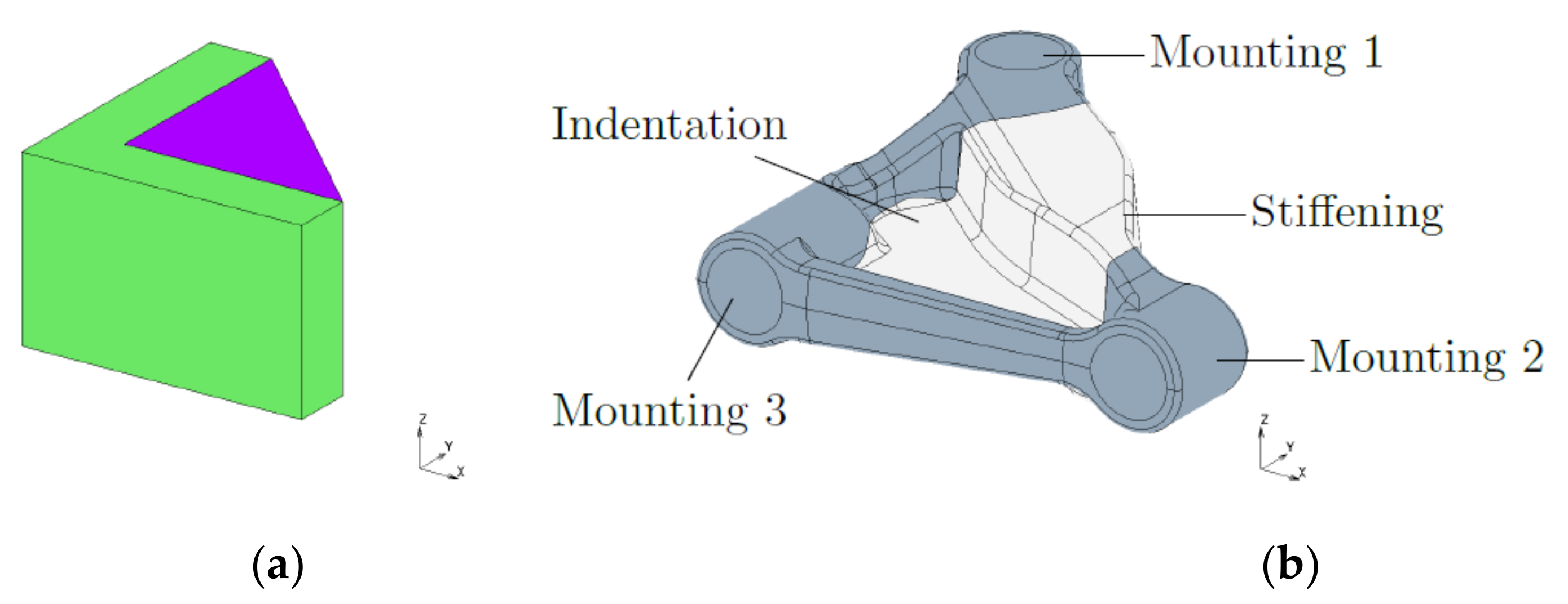
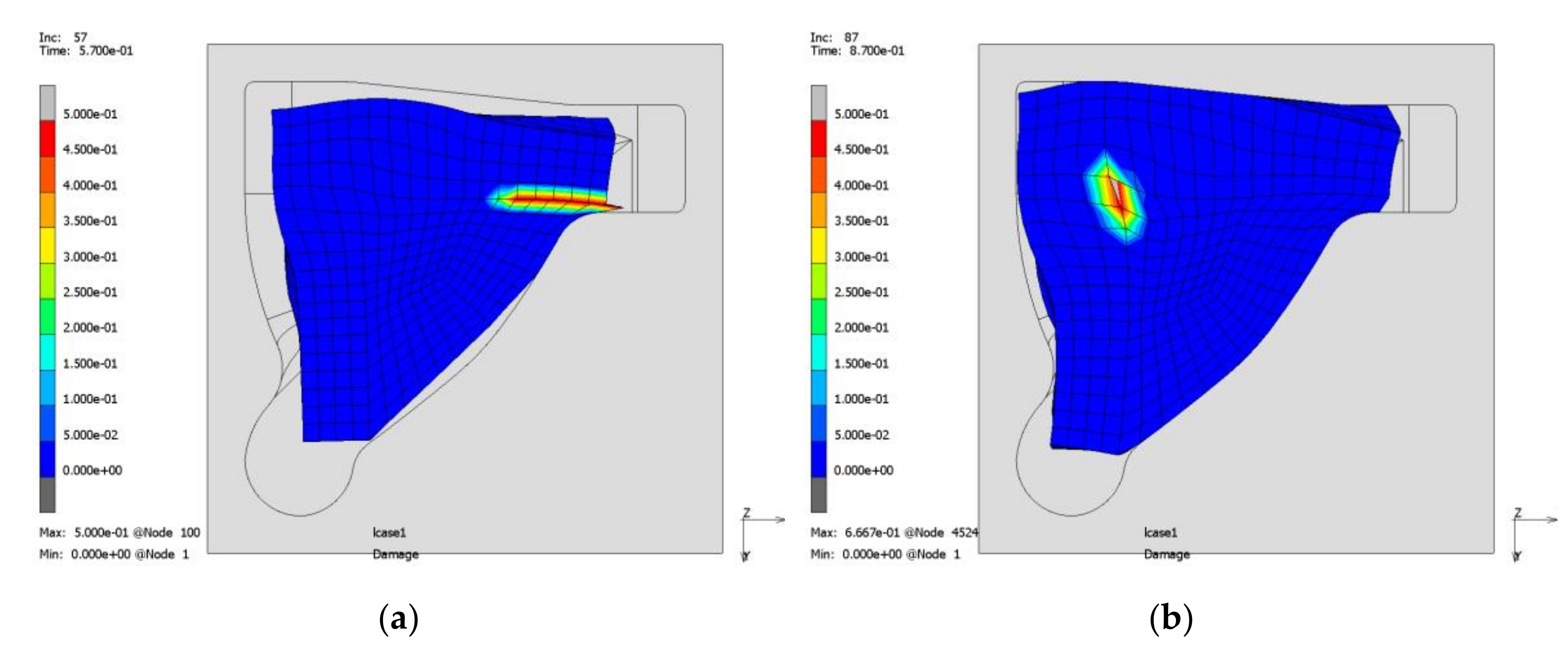
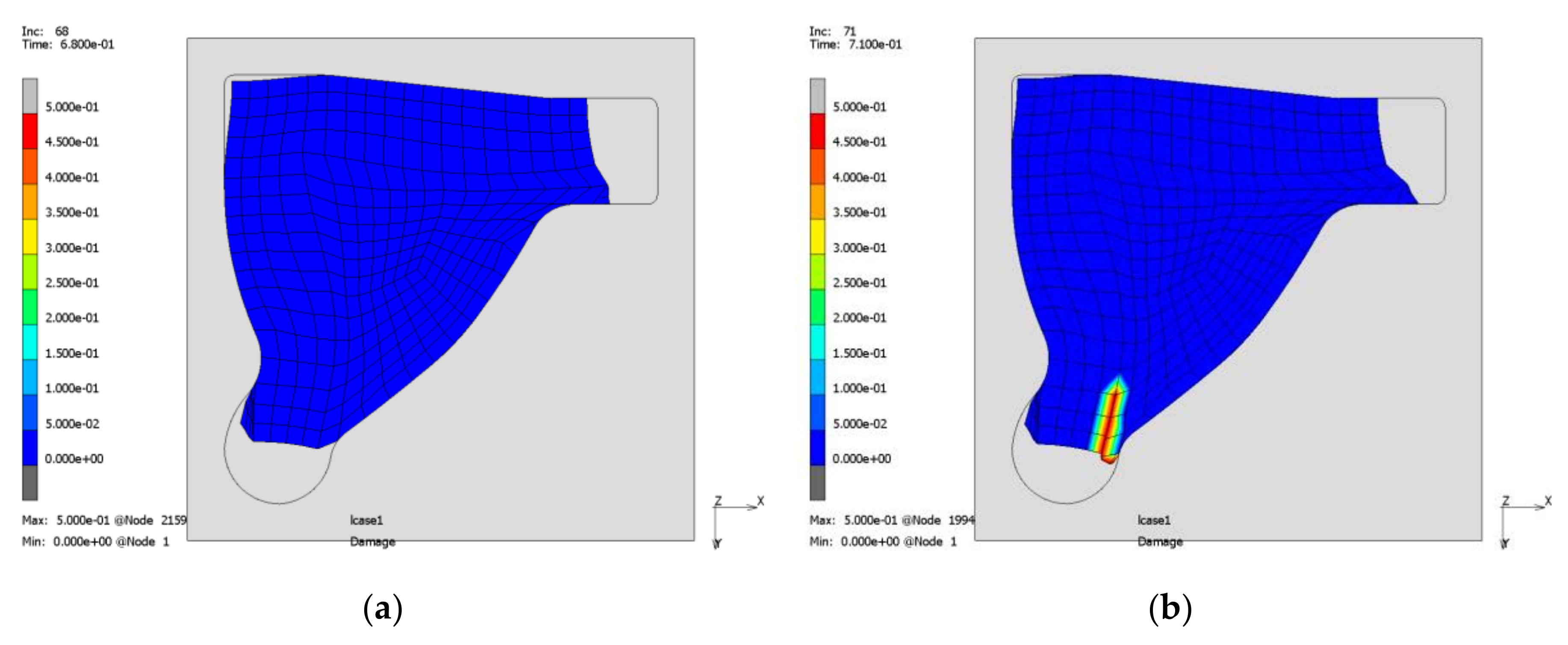
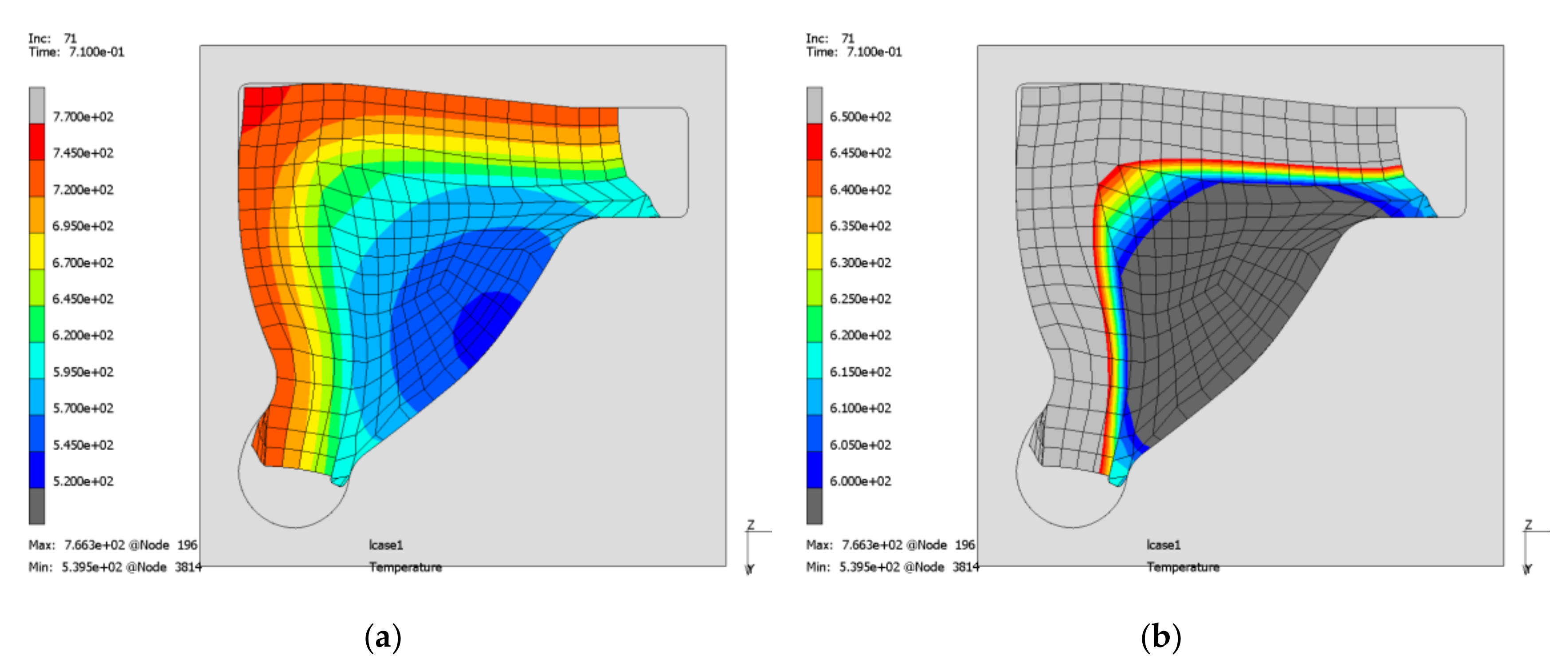
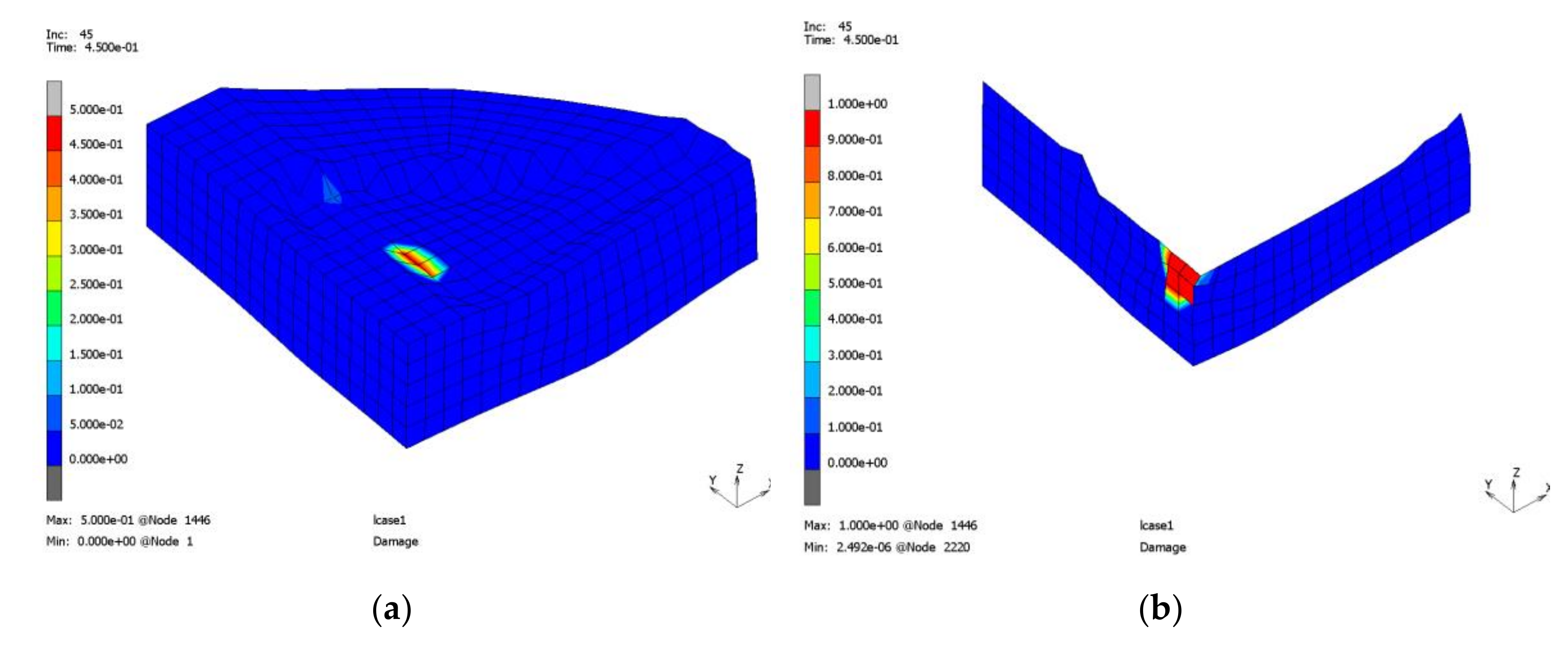
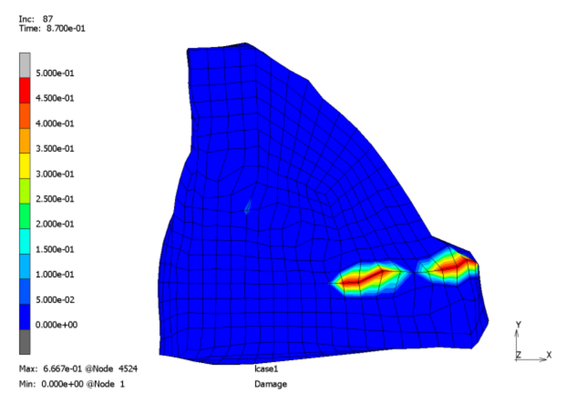
5. Simulation of a Transverse Link
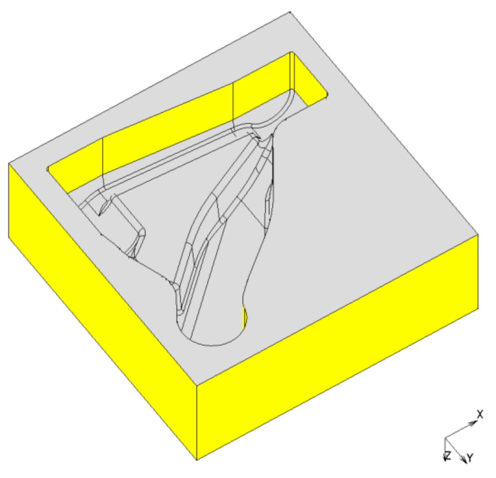
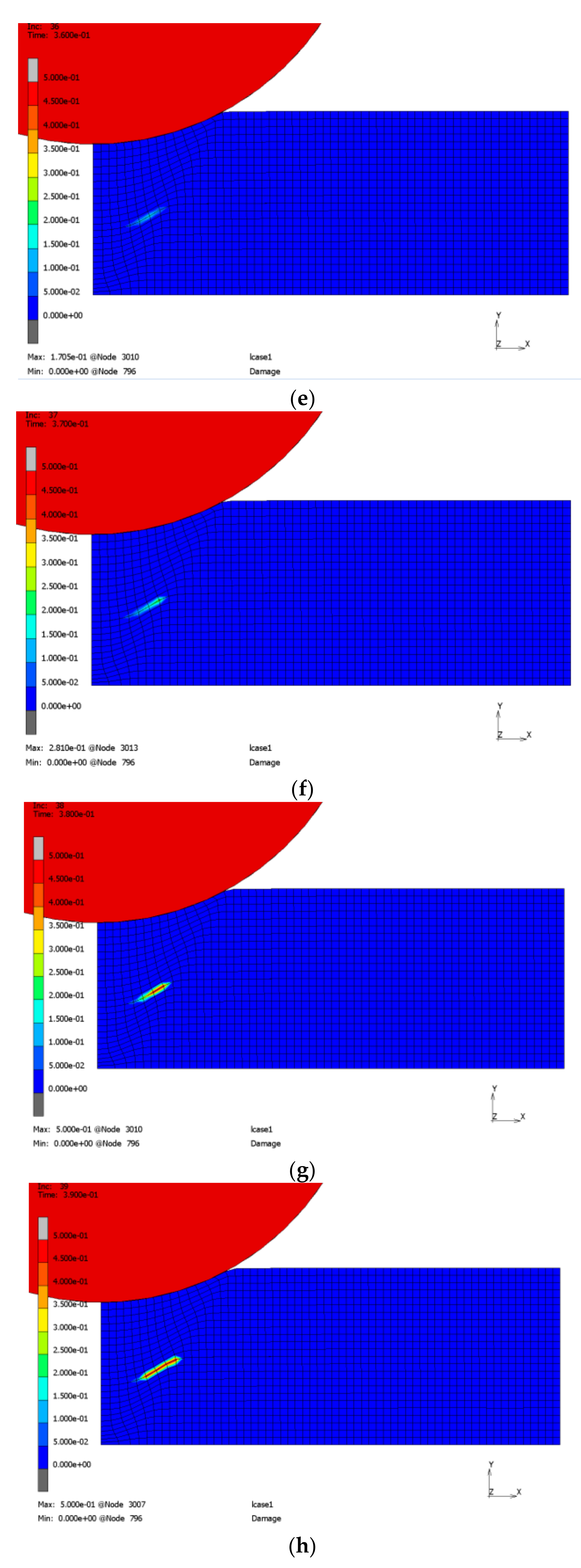
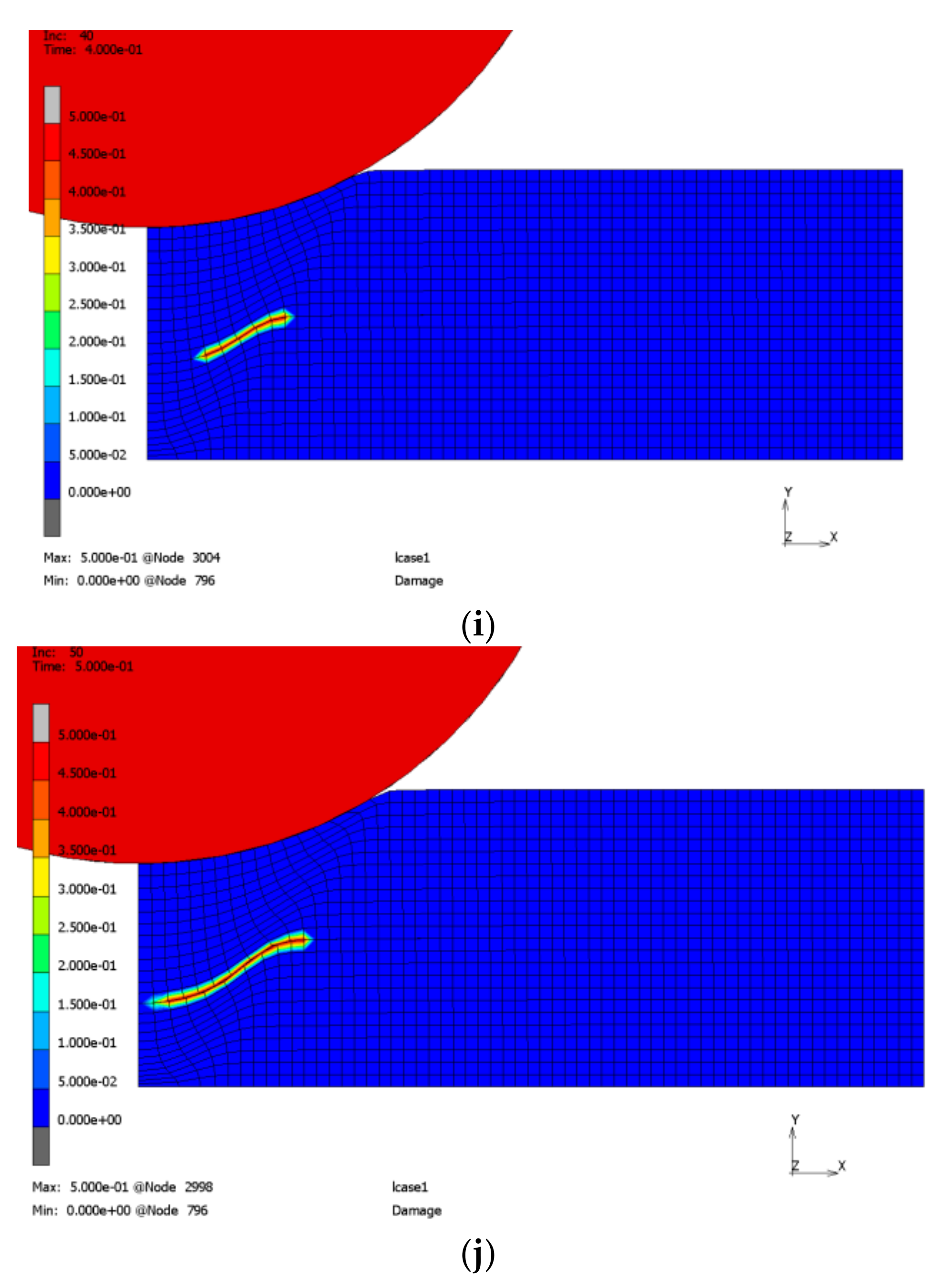
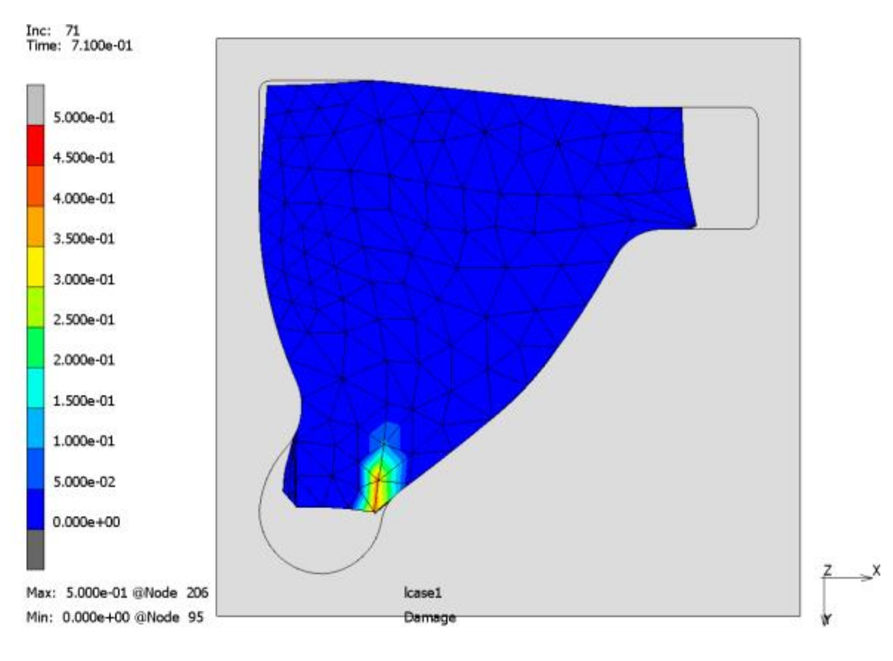
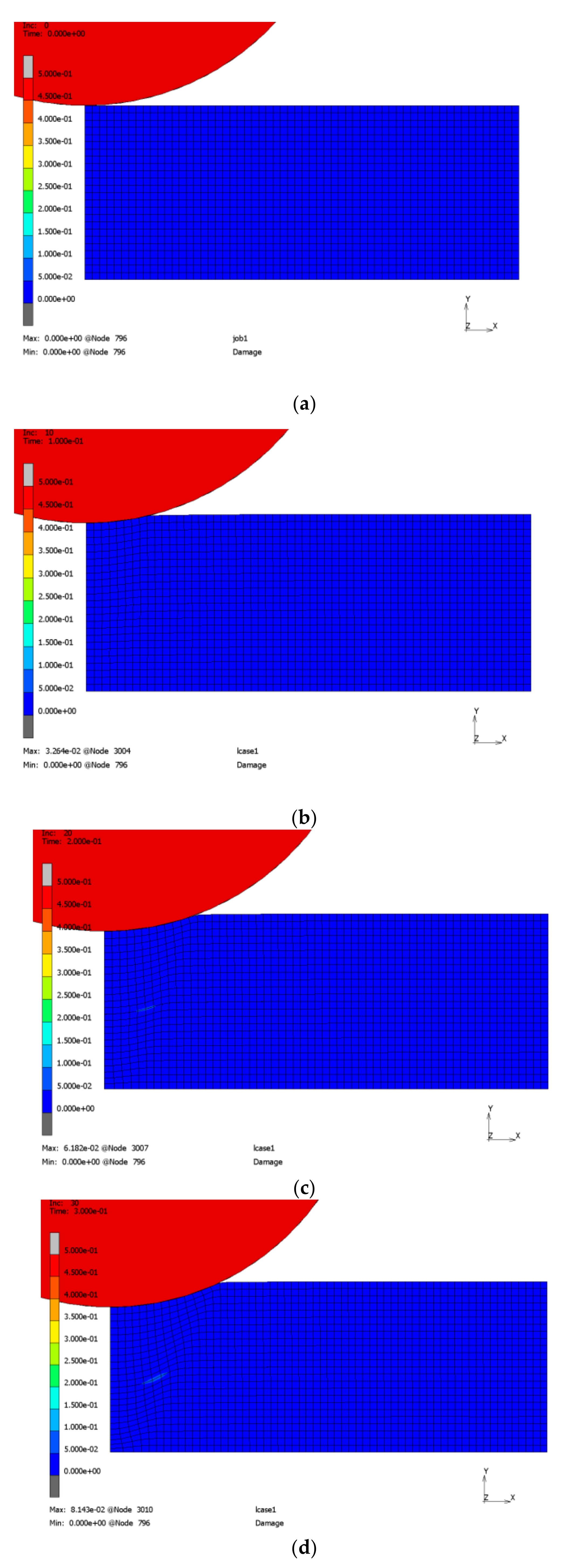
6. Indentation Test
7. Conclusions
- (1)
- The intended geometry contains severe deformation affecting the joining zone.
- (2)
- A more similar geometry of the raw component and the formed component would reduce the probability of failure initiation here.
- (3)
- The starting position in the form significantly influences the process and should be fixed.
- (4)
- A closed die process with burr prevention should be considered to prevent zones with very large deformation where a crack initiation might be triggered.
Author Contributions
Funding
Conflicts of Interest
References
- Geplanter Sonderforschungsbereich 1153—Prozesskette zur Herstellung hybrider Hochleistungsbauteile durch Tailored Forming—Einrichtungsantrag. 2014.
- Herbst, S.; Dovletoglou, C.N.; Nuernberger, F. Method for Semi-Automated Measurement and Statistical Evaluation of Iron Aluminum Intermetallic Compound Layer Thickness and Morphology. Met. Microstruct. Anal. 2017, 6, 367–374. [Google Scholar] [CrossRef] [Green Version]
- Behrens, B.A.; Bonhage, M.; Bohr, D.; Duran, D. Simulation Assisted Process Development for Tailored Forming. Mater. Sci. Forum 2019, 949, 101–111. [Google Scholar] [CrossRef] [Green Version]
- Töller, F.; Löhnert, S.; Wriggers, P. Bulk material models in Cohesive Zone Elements for simulation of joining zones. Finite Elements Anal. Des. 2019, 164, 42–54. [Google Scholar] [CrossRef]
- Töller, F.; Löhnert, S.; Wriggers, P. Membrane mode enhanced cohesive zone elements. Eng. Comput. 2020. Unpublished work. [Google Scholar]
- Lemaitre, J.; Desmorat, R. Engineering Damage Mechanics: Ductile, Creep, Fatigue and Brittle Failures; Springer Science & Business Media: Berlin/Heidelberg, Germany, 2005. [Google Scholar]
- MSC.Software Corporation. MSC.Marc Volume B: Element Library. version 2019.
- MSC.Software Corporation. MSC.Marc Volume D: User Subroutines and Special Routines. version 2019.
- Töller, F.; Löhnert, S.; Wriggers, P. Thermo-mechanical coupling for internal thickness extrapolation elements. In Proceedings of the 8th GACM Colloquium on Computational Mechanics: For Young Scientists from Academia and Industry, Kassel, Germany, 28–30 August 2019; Gleim, T., Lange, S., Eds.; Kassel University Press GmbH: Kassel, Germany, 2019. [Google Scholar]
- Behrens, B.-A.; Chugreev, A.; Selinski, M.; Matthias, T. Joining zone shape optimisation for hybrid components made of aluminium-steel by geometrically adapted joining surfaces in the friction welding process. In Proceedings of the AIP Conference Proceedings; AIP Publishing: College Park, MD, USA, 2019; Volume 2113, p. 040027. [Google Scholar]


| Number of Elements in Horizontal Direction | Failure in Increment | Failure Position from Left Corner |
|---|---|---|
| 10 | 59 | 0.21 mm |
| 20 | 47 | 1.40 mm |
| 30 | 43 | 0.93 mm |
| 40 | 40 | 1.20 mm |
| 50 | 39 | 1.16 mm |
| 60 | 37 | 1.13 mm |
© 2020 by the authors. Licensee MDPI, Basel, Switzerland. This article is an open access article distributed under the terms and conditions of the Creative Commons Attribution (CC BY) license (http://creativecommons.org/licenses/by/4.0/).
Share and Cite
Töller, F.; Löhnert, S.; Wriggers, P. Applying Membrane Mode Enhanced Cohesive Zone Elements on Tailored Forming Components. Metals 2020, 10, 1333. https://doi.org/10.3390/met10101333
Töller F, Löhnert S, Wriggers P. Applying Membrane Mode Enhanced Cohesive Zone Elements on Tailored Forming Components. Metals. 2020; 10(10):1333. https://doi.org/10.3390/met10101333
Chicago/Turabian StyleTöller, Felix, Stefan Löhnert, and Peter Wriggers. 2020. "Applying Membrane Mode Enhanced Cohesive Zone Elements on Tailored Forming Components" Metals 10, no. 10: 1333. https://doi.org/10.3390/met10101333
APA StyleTöller, F., Löhnert, S., & Wriggers, P. (2020). Applying Membrane Mode Enhanced Cohesive Zone Elements on Tailored Forming Components. Metals, 10(10), 1333. https://doi.org/10.3390/met10101333