Article

Application of a Novel Chamfered Mold to Suppress Corner Transverse Cracking of Micro-Alloyed Steel Slabs

1
State Key Laboratory of Advanced Metallurgy, University of Science and Technology Beijing, Beijing 100083, China
2
Shougang Group Co., Ltd. Research Institute of Technology, Beijing 100043, China
*
Author to whom correspondence should be addressed.
Metals 2020, 10(10), 1289; https://doi.org/10.3390/met10101289
Submission received: 7 July 2020 / Revised: 9 September 2020 / Accepted: 11 September 2020 / Published: 26 September 2020
(This article belongs to the Special Issue Casting and Solidification Processing)

Abstract

:
A novel chamfered mold is developed to solve the problem of corner transverse cracking in micro-alloyed steel slabs. The shape of the slab was changed from four corners and sides to eight corners and sides due to the use of a chamfered mold. Based on numerical simulation, the solidification and heat transfer of different steel grades in the mold are studied. The results reveal rapid solidification shrinkage of molten steel in the upper area of the mold and slow solidification shrinkage in the lower area; thus, a double-taper mold is designed according to these results. The first area of the variable taper falls in the range of 250–400 mm from the top of the mold, and the design method of double inclined water channels in the chamfered face is found to be the most helpful for the formation of a uniform initial shell and reducing hotspots of the mold. Actual production results show that the quality of the slab is better when the heat flux of the narrow face is larger than that of the broad face. Corner transverse cracking in micro-alloyed steels is greatly reduced from an incidence of 4.2% to less than 0.3%. In addition, the chamfered mold is applied in IF (interstitial free) steel production, and the edge quality of hot rolled sheets is found to also be dramatically improved.

1. Introduction

Corner transverse cracks, which usually occur in the slab continuous casting and appear along vibration marks at the corners of slabs, have attracted global attention regarding the formation mechanism of this defect [1,2]. The deformation is induced by thermal contraction during the δ-to-γ transformation [3], and the plasticity of the slab is poor due to the transformation from austenite to ferrite at approximately 900 °C. In addition, corner transverse cracks can easily arise from vibration marks. Toishi et al. [4] studied the critical strain for crack generation as measured by high-temperature tensile tests and simulation and found that the depth of the oscillation marks had a greater influence on crack formation than changes in the width. Tanaka et al. [5] found that positive and negative segregation at the vibration marks also aggravated the generation of corner transverse cracks.
Corner transverse cracks of Nb, V, and Ti micro-alloyed steel slabs with a carbon content of 0.07–0.17% are more serious than those of other alloys due to precipitation at austenite grain boundaries [6]. The hot ductility of typical steels has been measured; the temperatures in the third brittle zone are concentrated mostly between 700 and 900 °C, and the actual temperatures of slabs at the stage of bending and straightening measured by infrared temperature probes lie within this temperature range [7,8,9]. Some scholars have also studied the obvious correlations between the surface microstructures of slabs and cracks. They found that coarser austenite grains reduce the hot ductility and promote cracking. For hypo-peritectic steels in particular, the uneven solidification front leads to grain coarsening, which aggravates crack generation [10,11,12].
To solve these problems, Toru KATO developed the technique of SSC (surface structure control cooling); this method prevents transverse cracking and enables microstructure control by a dispersion of uniform fine precipitates, such as (Ti, Nb) (C, N) [13]. However, to realize SSC cooling, the equipment must be reconfigured, which does not only affect production but also increases the required facility investment.
According to the above analysis, it is challenging to solve the problem of corner transverse cracking during the slab continuous casting using traditional measures. In response, some studies have implemented chamfered mold technology. Analyses have indicated that when a chamfered face is designed with a single water channel, the cooling effect of the face is insufficient and cannot meet the requirements of slab production at a high casting speed [14]. The variable taper of the narrow face of the mold is 240 mm from the top of the mold, while the variable taper actual contact area of the narrow face with molten steels is only 140 mm from the top of the mold, which cannot completely cover the area with large shrinkage during the continuous casting process of medium carbon steels and hypo-peritectic steel. Moreover, when the chamfered face is cooled by two or three water holes and one water channel, the cooling effect of the face remains insufficient and still fails to meet the requirements of slab production at high casting speeds [9,15,16,17,18].
Based on the above analysis, the solidification and heat transfer behavior of different molten steels in a chamfered mold were studied in the present study, and a new water channel in the chamfered faces and a variable taper area were designed. As a result, the flawless production of ultralow carbon, low carbon, medium carbon, and hypo-peritectic steels under high speed was realized.

2. Mathematical Models

2.1. Calculation Model of Thermal Shrinkage

To establish a reasonable taper of a narrow face in a mold, this paper studies the thermal shrinkage behavior of different steel grades in a mold, and a two-dimensional slice model with a moving coordinate system is used to evaluate the thermal shrinkage of a slab in a mold.

2.1.1. Mesh Division

Considering the symmetry of the structure and boundary conditions, one quarter of the slab is modeled to save the calculation time, the average mesh size is 0.0043 m. The calculation domain and mesh division details of the model are shown in Figure 1.

2.1.2. Heat Transfer Equation

According to the two-dimensional slice hypothesis, the simplified equation of slab solidification heat transfer is expressed by Equation (1) [19,20].
x ( k e f f T x ) + y ( k e f f T y ) + ρ L f s t = ρ C P T t ,
where T is the temperature, keff is the effective thermal conductivity, ρ is the material density, L is the latent heat of fusion, fs is the solid phase rate, Cp is the specific heat capacity of the material, and t is the time.

2.1.3. Heat Transfer Boundary Conditions

Center of the Slab:
Heat transfer in the slab is symmetrical about the central axis, and the heat transfer boundary of the central symmetrical axis can be regarded as an adiabatic boundary, which is expressed by Equations (2) and (3).
k T x = 0 ,
Surface of the Slab:
k T x = A B t ,   k T y = A B t ,
A, B is the constant of instantaneous heat flux calculation at different positions in the casting direction in the mold.
A = 2680000 W / m 2
B = 1.5 ( 2680000 q ¯ ) / L m v
q ¯ is the average heat flux of the mold, which is expressed by Equation (6):
q ¯ = C w × w × Δ T / ( S e f f × 60 ) W / m 2
Here, Cw—Specific heat capacity of water, J/kg °C;
w—Amount of water for mold, L/min;
ΔT—Water temperature difference between inlet and outlet of mold, °C;
Seff—Effective heat transfer area of mold, m2;
v—Casting speed, m/min;
Lm—Effective heat transfer length of mold, m.
The instantaneous heat flux is calculated according to relevant process data from the broad and narrow faces, as shown in Table 1.

2.2. Thermomechanical Coupling Model

To study the influence of the cooling water channel design in the chamfered mold during the slab continuous casting, a thermo-mechanical coupling model based on the 2D slice hypothesis is established to evaluate the uniformity of narrow face cooling in the mold.

2.2.1. Mesh Division

The model includes a copper plate and slab. Based on the symmetry of physical conditions and boundary conditions, 1/4 of the slab is selected for calculation in the domain of the model. There are 10,650 units with an average size of 0.002 m and 3765 of mold units with an average size of 0.004 m, which is shown in Figure 2.

2.2.2. Thermomechanical Boundary Conditions

Symmetrical Boundary:
According to the symmetry, the center of symmetry between the slab and the copper plate should be an adiabatic boundary, meaning that the perpendicular heat flux should be zero, which can be expressed by Equation (7).
q = 0 ,
If no heat transfer boundary condition is applied to the boundary, it is automatically treated as an adiabatic boundary in the finite element calculation. In addition, a fixed displacement boundary is applied in the direction perpendicular to the symmetry line, which can be expressed by Equation (8).
u x = 0 ,
Outer Surface of the Mold:
The convective heat transfer occurs between the external surface of the mold and the cooling water, and the heat flux can be determined by Equation (9).
Q = h w ( T M o u t T w ) ,
Here, Q is the heat flux; TM-out is the temperature at the surface of the copper channel; and Tw is the cooling water temperature of the mold; hw is the heat transfer coefficient of the cooling water of the mold, which is determined through Equation (10).
h w × D H k w = 0.023 × ( ρ w u w D H μ w ) 0.8 ( C P w μ w k w ) 0.4
Thermophysical data to calculate the hw are given in Table 2.
Heat Transfer between the Slab and the Copper Plate:
Obtaining the interface state between the shell and hot surface of the mold copper plate is the key point of coupling the temperature field and the stress field in the continuous casting mold. In the model, the heat transfer between the mold and the copper plate is coupled by the secondary development subroutine according to the contact state.
The thermal boundary condition between the solidified shell surface and the mold wall is modeled using the interfacial heat transfer coefficient which is a function of air gap thickness and temperature of slab surface [21]. The heat flux transferred from the solidified shell to the mold wall could be described by the following equation:
q = h f × ( T b T m i n )
In which, q is the heat flux transferred from the solidified shell to mold wall, W·m−2; Tb is the temperature of solidified shell surface, K; Tm-in is the temperature of mold wall inner surface, K; hf is the interfacial heat transfer coefficient between the solidified shell and mold wall depending on the air gap size, W·m−2·K−1, which is calculated through the self-developed subroutine.

2.3. Steel Grade Parameters

2.3.1. Composition of Different Steel Grades

In the study, 510L and Q345X are selected as the research materials. The compositions are shown in Table 3.
The liquidus temperature and solidus temperatures are shown in Table 4.

2.3.2. Coefficient of Thermal Expansion

According to the transformation law of steel in solidification processes, the linear expansion of the slab within the solidification temperature range can be calculated [22], which is shown in Figure 3.

2.3.3. Constitutive Equation of Slab Deformation

The deformation behavior of the slab in the model is described by a constitutive equation based on the stress, inelastic strain, temperature, and time as proposed by Kozlowski et al. [23], and expressed as Equations (12)–(16).
ε ˙ = C exp ( Q T ) σ n t m
C = 0.3091 + 0.2090 ( % C ) + 0.1773 ( % C ) 2
Q = 17160
n = 6.365 4.521 × 10 3 T + 1.439 × 10 6 T 2
m = 1.362 + 5.761 × 10 4 T + 1.982 × 10 8 T 2
where σ and ε represent the equivalent stress and creep rate, respectively.
The elastic modulus and Poisson ratio of the slab and copper plate are described by nonlinear functions of temperature.

3. Results and Discussion

The solidification and heat transfer of molten steel in the chamfered mold change when the slab is changed from four corners and faces to eight corners and faces. The narrow face of chamfered mold and common mold are shown in Figure 4.
With this change, it becomes more difficult to ensure the uniform cooling of each face in the mold. Since the thickness of the copper plate at the chamfered face is thicker than that at the narrow face, the design of the water channel at the chamfered face is very important. Therefore, it is necessary to optimize the taper of the narrow face.

3.1. Taper Design of the Narrow Face

3.1.1. Thermal Shrinkage of Typical Steel Grades

To save the calculation time, 1/4 of the slab is selected for calculation in the model, and the surface mesh size is smaller than the center mesh size. The medium carbon alloy steel (Q345X) and hypo-peritectic steel (510L) are 230 mm × 1800 mm in actual production, and the casting speed is 1.1 m/min. The results are as follows.
Figure 5 shows the trend of thermal shrinkage during solidification of the slab for the same casting speed of Q345X and 510L. The lines in the figure show the trends of thermal shrinkage at different positions from the surface. The heat flux close to the meniscus is large, the shell is thin, and the thermal shrinkage of the slab increases with the increasing distance from the meniscus. The areas with large shrinkage lie 150–300 mm from the meniscus of the mold, and the corresponding larger taper than the common mold should be used.
In the solidification process, there is an air gap between the mold and the shell, and the thermal shrinkage is small, so a smaller taper should be used. It can be found from the calculation that the solidification characteristics of different steel grades in the mold are different. The shrinkage of the hypo-peritectic steel in the mold is greater than that of the medium carbon steel. The maximum shrinkage of the hypo-peritectic steel at 1.24 mm from the surface of slab is approximately 10.0 mm, and the maximum shrinkage of the medium carbon steel is approximately 7.6 mm.

3.1.2. The Thermal Shrinkage of Typical Steel Grades with Different Casting Speeds
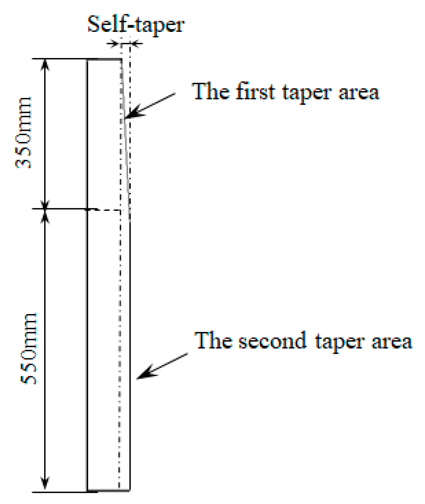
The thermal shrinkage of Q345X and 510L at different casting speeds are calculated. As shown in Figure 6, with the increasing casting speed, the thermal shrinkage of the slab gradually decreases, and the trends of thermal shrinkage at different positions from the surface are essentially consistent.
The thermal shrinkage coefficient of 510L is larger than that of Q345X. The maximum surface thermal shrinkages of the Q345X and 510L slabs at different speeds are shown in Figure 7. With the increasing casting speed, the maximum surface thermal shrinkages of the slabs decrease gradually; correspondingly, a smaller taper should be adopted. The maximum shrinkage range of Q345X is 7.1–8.5 mm, and that of 510L is 9.5–11.2 mm.

3.1.3. Taper Design

According to the simulation analysis of Q345X and 510L, considering the design requirements of the different sections, different casting speeds and different steel grades, the first taper area is 350 mm from the top of the mold, the second taper area is below the first taper area, the double mold is shown in Figure 8.
Through numerical simulation, the narrow face of the mold is designed with a self-taper of 0.6–3 mm. The test results of Q345X are shown in Table 5.
Through a lot of experiments, it is found that the taper of the belt is better than 1.2 mm.

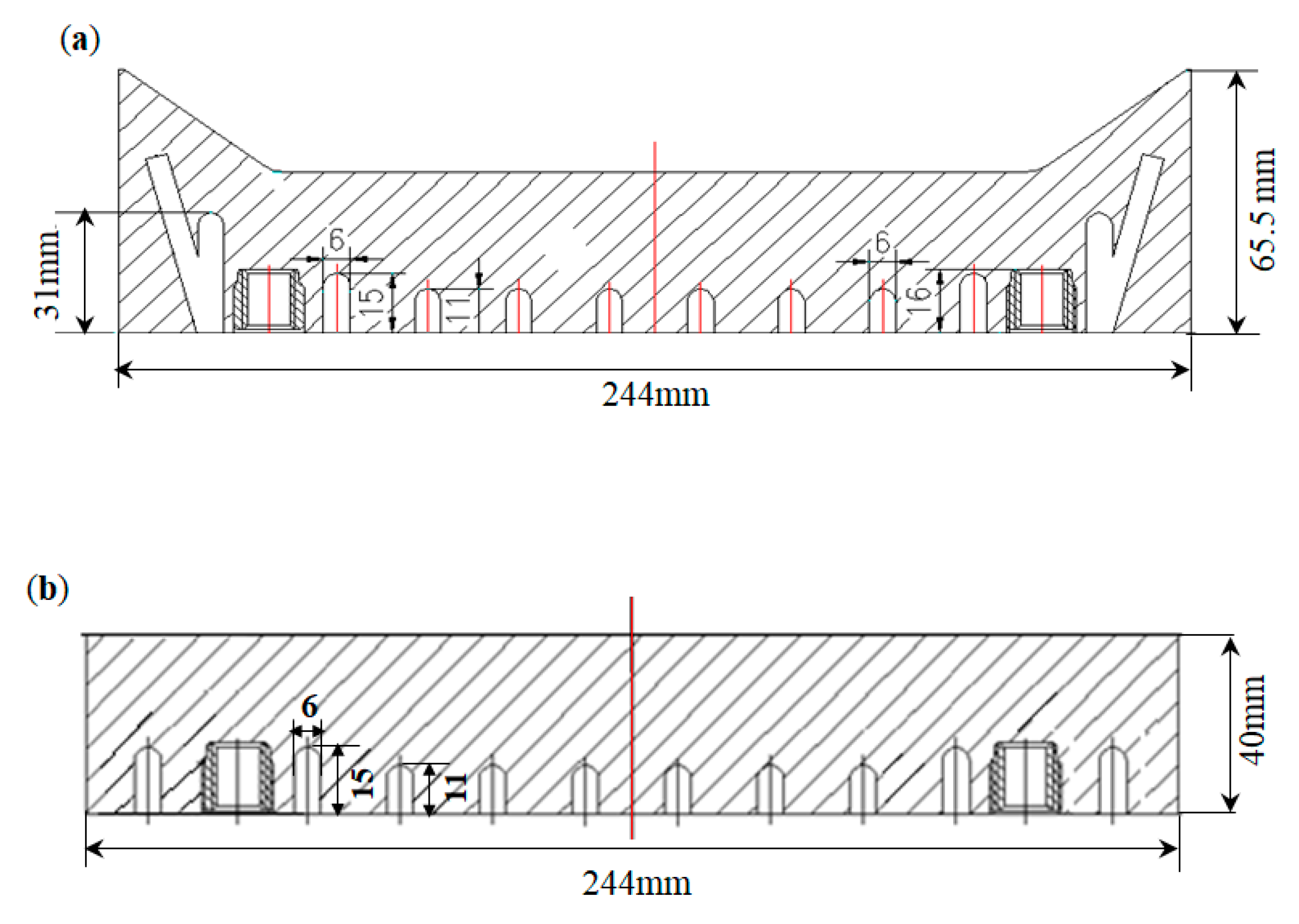
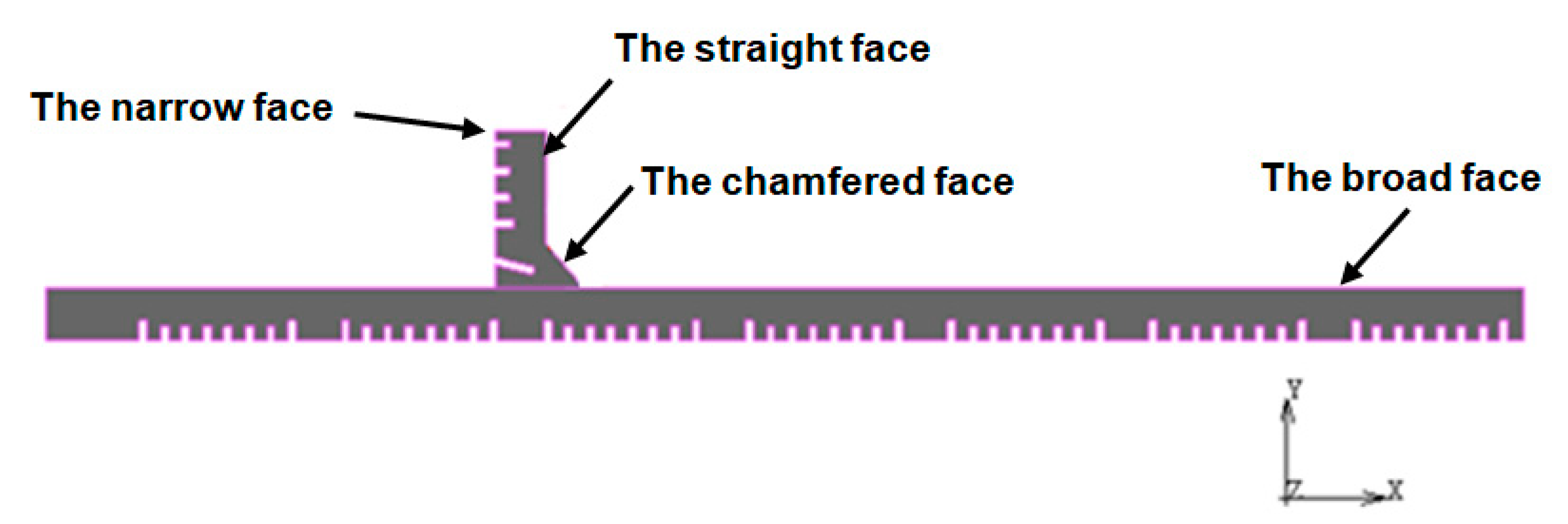
3.2. Design of Chamfered Face Water Channels

3.2.1. Current Situation

The narrow face includes straight and chamfered faces, first, the narrow face of the mold is designed. There is an inclined water channel in the chamfered face, and the width of the water channel is 6 mm; the chamfered mold is shown in Figure 9.
The different tapers, casting speeds, and water flowrates of the mold were experimentally tested. Longitudinal cracks appeared at the corners of the slabs, and the experimental results were not ideal. The chamfered mold was dissected and observed, and the chamfered face is shown in Figure 10. There are clearly different colors at the dotted line area, indicating that the copper plate at the dotted line area exhibits hotspots and therefore that the cooling strength is insufficient.

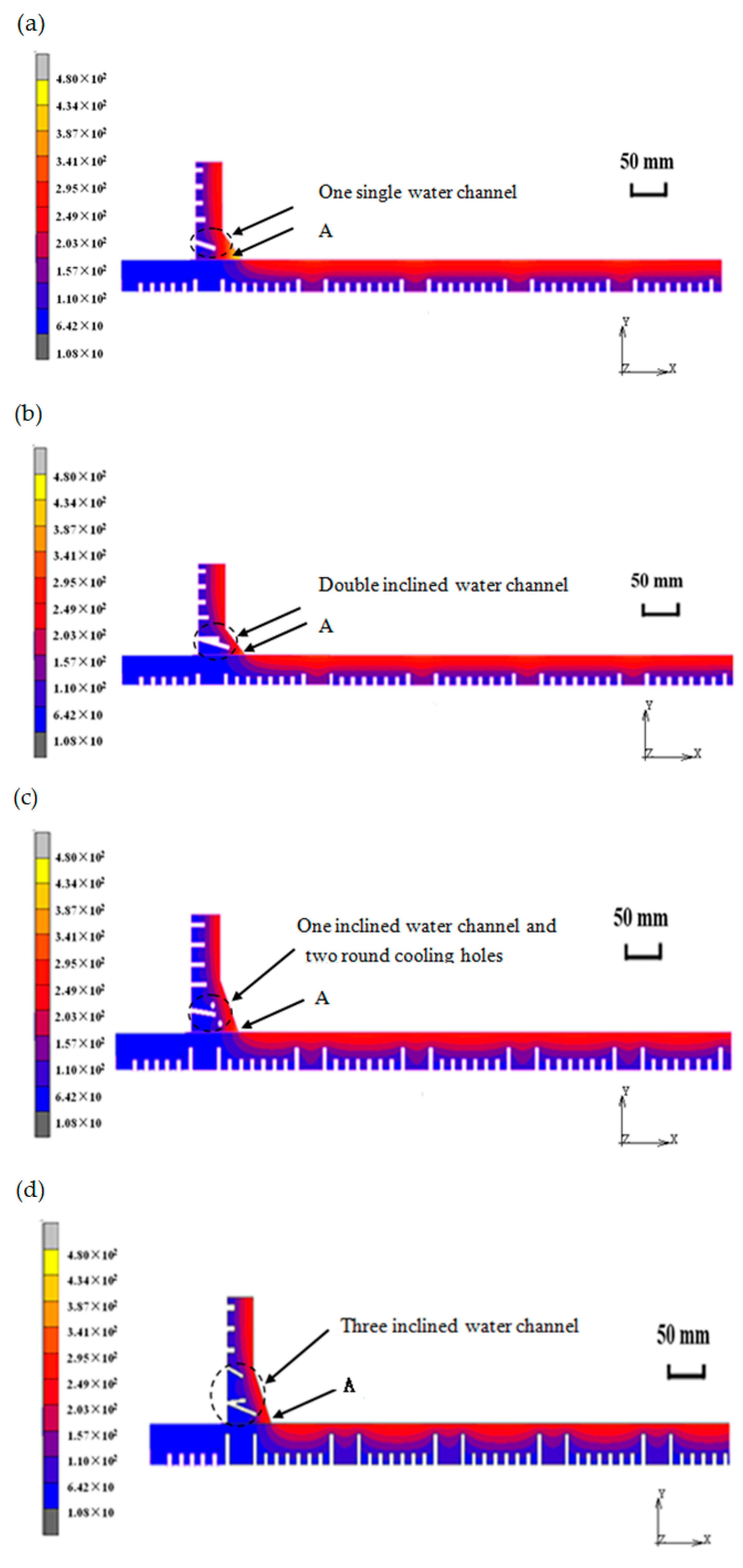
3.2.2. Optimal Design of the Water Channels

To analyze the influence of the water channel design of the chamfered mold, different cooling schemes of the narrow face water channel are designed. The water channel design scheme is shown in Table 6.
The model is simplified to 1/4 of the model. Assuming a good lubrication condition of the powder at the meniscus and a good contact condition between the molten steel and the copper plate, the thermal state of the copper plate is calculated. The temperature of the copper plate reflects differences in the heat transfer capacity at different positions of the mold, which can indirectly reflect the uniformity of the primary shell of the slab. The simulation results of different molds are shown in Figure 11.
A hotspot (A) appears close to the broad face of the mold. To analyze the difference of each scheme, the hotspot temperatures are shown in Figure 12.
The scheme using one single water channel has the highest hotspot temperature, and the scheme using double inclined water channels has the lowest hotspot temperature. The hotspot temperatures of Schemes 3 and 4 lie between these two extremes.
In summary, the heat transfer of the mold near the hotspot area is greatly improved over that of Scheme 1, and Scheme 2 is expected to better prevent the corner longitudinal cracking than the other schemes.

4. Industrial Application

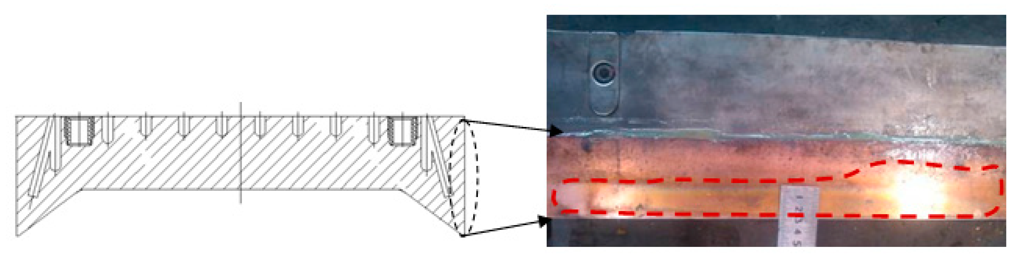
4.1. Heat Transfer Process of the Chamfered Mold

To study the heat flux of the chamfered mold, the heat flux, which is expressed by Equation (5), industrial tests are carried out. The chamfered mold is applied to one strand, and the common mold is applied to the other strand. The results are shown in Figure 13.
First, the heat flux of the chamfered mold is studied. The average heat flux of the narrow face (1.58 MW/m2) is larger than that of the broad face (1.43 MW/m2). The range of ratios of narrow face heat flux to broad face heat flux is 0.96~1.18, and the average value is 1.1.
Next, the heat flux of the common mold is studied. The heat flux of the narrow face (1.44 MW/m2) is smaller than that of the broad face (1.51 MW/m2), the range of ratios of narrow face heat flux to broad face heat flux is 0.86–1.08, and the average value is 0.94. We conclude that the average value of the chamfered mold and common mold are different.
Based on the analysis of the heat flux value of the narrow face to that of the broad face of the chamfered mold and common mold, we conclude that the heat flux of the two chamfered faces is applied to the narrow face, the contact area with the shell increases due to the increase in the chamfered face area. An air gap exists between the narrow face and the broad face, so the heat flux of the increased area is transmitted mostly from the narrow face. In addition, due to the increase in the chamfered face area, the contact area between the broad face and the shell is reduced, so the heat flux from the broad face is reduced. A 230 mm × 1600 mm section is taken as an example; the contact lengths of the shells of the chamfered mold and common mold are shown in Table 7.

4.2. Study on Cooling of the Chamfered Mold

The relationship between the amount of water for the narrow face and the water difference between inlet and outlet of mold is studied. The operating conditions as shown in Figure 14 are given in Table 8.
As shown in Figure 14, the water temperature difference of the narrow face gradually decreases from 9.35 to 6.58 °C as the amount of water for the narrow face increases from 460 to 600 L/min. Notably, as the amount of water for the narrow face increases from 540 to 600 L/min, the water temperature difference does not change much. Thus, the longitudinal crack control benefits from 540 to 600 L/min.

4.3. Research on Taper Control of the Chamfered Mold

The taper control of a double-taper mold is different from that of a common mold. The average taper can reflect the shrinkage of molten steel better when molten steel solidifies in the mold, so the same average taper is adopted for different slab widths. The taper control of different widths is shown in Figure 15.

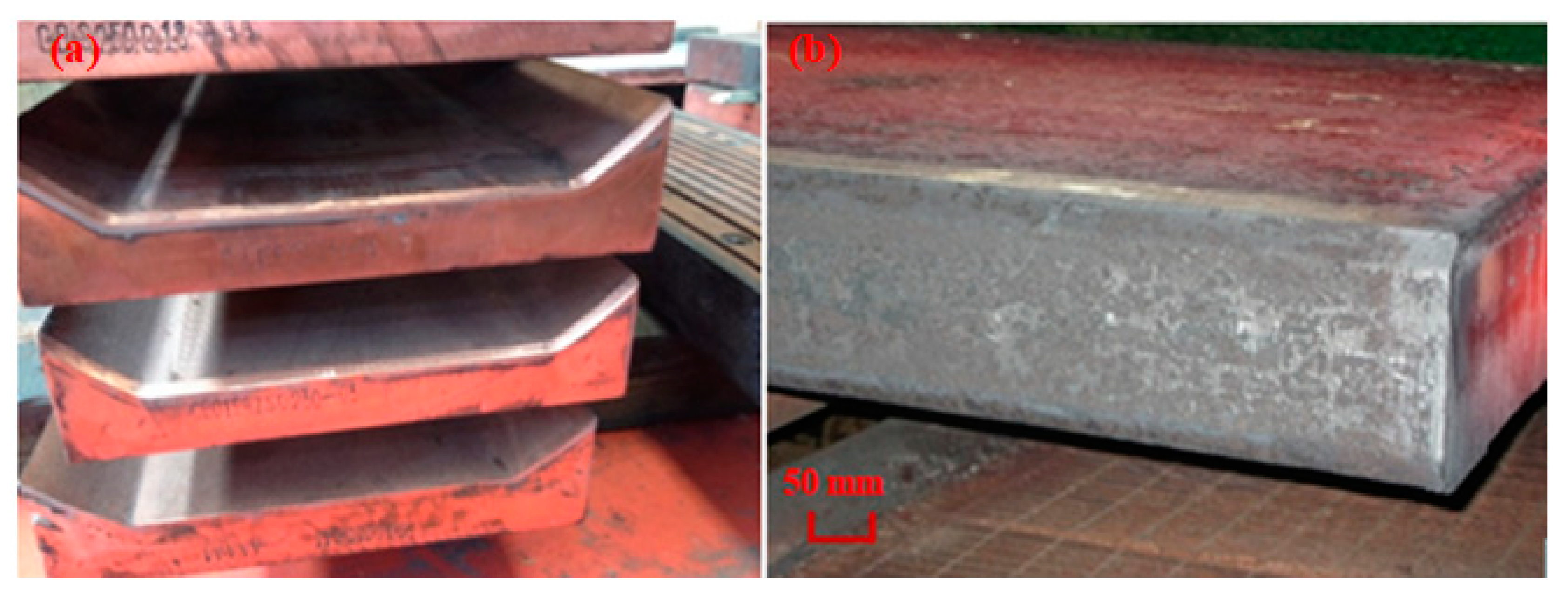
4.4. Application Effect of the Chamfered Mold

The chamfered mold is used for the production of the steels with carbon content below 0.8%, including ultra-low carbon steel, low carbon steel, hypo-peritectic steel, medium carbon steel, and high carbon steel.
The chamfered mold is shown in Figure 16a, and the slab produced by the chamfered mold is shown in Figure 16b.
Through the use of chamfered mold, the corner temperature of chamfered slab is increased by 30–80 °C compared with that of the common mold. The increase of temperature is closely related to the continuous casting parameter, the design of chamfered mold water channels, and the size design. The increase of corner temperature is beneficial to the control of transverse corner crack and edge defect of the hot rolled sheet.
Figure 17 shows the corner transverse cracks of the slab and the edge defects of the hot rolled sheet obtained with the common mold.
(1)
The incidence of transverse corner cracks is the number of slabs with corner cracks detected divided by the total number of slabs detected.
(2)
The incidence of edge defects is the number of the hot rolled sheet with edge defects detected by the total number of hot rolled sheet detected.
The transverse corner cracks are checked by scarfing, and then by visual inspection. When the transverse corner crack appears on the slab, it is recorded as the slab with transverse corner crack. The edge defects are detected by the Pepsi Instrument, when the edge defects appear at the edge of the sheet, it is recorded as the edge defect of the sheet.
The corner transverse cracks of the slab and the edge defects of the hot rolled sheet are substantially improved by application of the chamfered mold.
The steels of carbon content from 0.07% to 0.20% with the chamfered mold technology, the incidence of corner transverse cracks decreases from 4.2% to 0.4%, as shown in Figure 18.
When the chamfered mold is applied to the IF steel (carbon content below 0.02%) casting, the edge defects of the hot rolled sheet are notably improved; the incidence of hot rolled sheet edge defects decreases from 4.7% to 0.6%. The maximum casting speeds of the ultralow carbon and hypo-peritectic steel are 1.6 and 1.4 m/min, respectively.

5. Conclusions

(1)
The shrinkage of hypo-peritectic steel in a mold is larger than that of medium carbon steel. A double-taper mold is designed according to experimentally obtained characteristics. The first area of the variable taper falls in the range of 250–400 mm from the top of the mold, the best area is 350 mm and the self-taper is within the range of 0.6–3 mm.
(2)
The design method of double inclined water channels in the chamfered face is the most helpful for the formation of a uniform initial shell and for reducing mold hotspots.
(3)
The average heat fluxes of the broad and narrow faces are 1.43 and 1.58 MW/m2, respectively. The heat flux of the narrow face is larger than that of the broad face. The range of heat flux ratios of the narrow face to the broad face is 0.96–1.18.
(4)
When the amount of water for the narrow face increases from 460 to 600 L/min, the water temperature difference between the inlet and outlet of mold decreases from 9.35 to 6.58 °C. When the amount of water increases from 540 to 600 L/min, the water temperature difference does not change much.
(5)
After the chamfered mold technology is applied, the incidence of corner transverse cracks decreases from 4.2% to 0.4%, and the incidence of hot rolled sheet edge defects decreases from 4.7% to 0.6%.

Author Contributions

Writing—original draft preparation, G.L.; formal analysis, Q.L.; writing—review and editing, C.J., H.L. and K.L.; data curation, B.C.; project administration, Q.L. All authors have read and agreed to the published version of the manuscript.

Funding

This research received no external funding.

Acknowledgments

The authors express sincere thanks to H.A. and J.Z. in the University of Science and Technology Beijing for their helpful assistance with the structure and format of this paper. The authors are grateful to W.M. and X.Y. in Beijing Shougang Co., Ltd. for their help during the experimental process.

Conflicts of Interest

The authors declare no conflict of interest.

References

  1. Suzuki, H.G.; Nishimura, T.; Yamaguchi, S. Characteristics of Embrittlement in Steels above 600 °C. Tetsu-to-Hagane 1979, 65, 2038–2046. [Google Scholar] [CrossRef] [Green Version]
  2. Takeuchi, E.; Brimacombe, J.K. The formation of oscillation marks in the continuous casting of steel slabs. Metall. Trans. B 1984, 15, 493–509. [Google Scholar] [CrossRef]
  3. Furumai, K.; Phillion, A.; Zurob, H. Calculation of Initial Stage of Solidified Shell Deformation during to Transformation in Mold. ISIJ Int. 2019, 59, 2036–2043. [Google Scholar] [CrossRef] [Green Version]
  4. Toishi, K.; Miki, Y.; Kikuchi, N. Simulation of Crack Initiation on the Slab in Continuous Casting Machine by FEM. ISIJ Int. 2019, 59, 865–871. [Google Scholar] [CrossRef] [Green Version]
  5. Takeuchi, E.; Brimacombe, J.K. Effect of oscillation-mark formation on the surface quality of continuously cast steel slabs. Metall. Trans. B 1985, 16, 605–625. [Google Scholar] [CrossRef]
  6. Mintz, B. The Influence to the Problem of Composition of Transverse on the Hot Cracking. ISIJ Int. 1999, 39, 833–855. [Google Scholar] [CrossRef]
  7. Maehara, Y.; Ohmori, Y. Microstructural change during superplastic deformation of ferrite/austenite duplux stainless steel. Metall. Trans. A 1987, 18, 663–672. [Google Scholar] [CrossRef]
  8. Mintz, B.; Arrowsmith, J.M. Hot-ductility behaviour of C-Mn-NbAl steels and its relationship to crack propagation during the straightening of continuously cast strand. Met. Technol. 1979, 6, 24–32. [Google Scholar] [CrossRef]
  9. Zhang, H.; Yang, C.; Wang, M.; Wang, X. Technology Development for Controlling Slab Transverse Corner Crack of Typical Micro-alloyed Steels. J. Iron Steel Res. Int. 2015, 22, 99–105. [Google Scholar] [CrossRef]
  10. Maehara, Y.; Yasumoto, K.; Sugitani, Y.; Gunji, K. Effect of Carbon on Hot Ductility of As-cast Low Alloy Steels. Trans. Iron Steel Inst. Jpn. 1985, 25, 1045. [Google Scholar] [CrossRef]
  11. Sato, D.; Ohno, M.; Matsuura, K. Phase-Field Simulations and Analysis of Effect of Dispersed Particles on Migration of Delta to Gamma Transformation Interface. Metall. Mater. Trans. A 2015, 46, 981–988. [Google Scholar] [CrossRef]
  12. Sricharoenchai, P.; Nagasaki, C.; Kihara, J. Hot Ductility of High Purity Steels Containing Niobium. ISIJ Int. 1992, 10, 1102–1109. [Google Scholar] [CrossRef] [Green Version]
  13. Kato, T.; Ito, Y.; Kawamoto, M. Prevention of Slab Surface Transverse Cracking by Microstructure Control. ISIJ Int. 2003, 43, 1742–1750. [Google Scholar] [CrossRef]
  14. Wang, W.J.; Li, B.H.; Zhu, Z.Y.; Liu, Y.; Wang, Y.L.; Guan, C.Y. Development and Application of Mould With Chamfered Corners for Continuous Casting of Slabs. J. Iron Steel Res. 2012, 24, 21–25. [Google Scholar]
  15. Zong, N.; Liu, Y.; Zhang, H.; Yang, J. Application of a chamfered slab technology to reduce straight edge seam defects of non-oriented silicon electrical steel generated during flexible thin slab casting process. Metall. Res. Technol. 2017, 114, 311. [Google Scholar] [CrossRef]
  16. Hu, P.; Zhang, H.; Wang, M.; Zhu, M.; Zhang, X.; Zhang, Y.; Zhang, Z. Application of a chamfered mold to improve corner defects of HSLA during slab continuous casting. Metall. Res. Technol. 2015, 112, 104. [Google Scholar] [CrossRef]
  17. Zong, N.; Liu, Y.; Zhang, H. Application of chamfered narrow face mold technology to reduce longitudinal surface crack defects of hyperperitectic steel generated during flexible thin slab casting process. Metall. Res. Technol. 2017, 114, 413. [Google Scholar] [CrossRef]
  18. Zong, N.; Liu, Y.; Ma, S.; Sun, W.; Jing, T.; Zhang, H. A review of chamfer technology in continuous casting process. Metall. Res. Technol. 2020, 117, 204. [Google Scholar] [CrossRef] [Green Version]
  19. Meng, X.; Zhu, M. Thermal Behavior of Hot Copper Plates for Slab Continuous Casting Mold with High Casting Speed. ISIJ Int. 2009, 49, 1356–1361. [Google Scholar] [CrossRef] [Green Version]
  20. Liu, X.D.; Zhu, M.Y. Finite Element Analysis of Thermal and Mechanical Behavior in a Slab Continuous Casting Mold. ISIJ Int. 2006, 46, 1652–1659. [Google Scholar] [CrossRef]
  21. Hibbeler, L.C.; Xu, K.; Thomas, B.G. Thermomechanical Modelling of Beam Blank Casting. Iron Steel Technol. 2009, 6, 60–73. [Google Scholar]
  22. Won, Y.M.; Thomas, B.G. Simple model of microsegregation during solidification of steels. Metall. Mater. Trans. A 2001, 32, 1755–1767. [Google Scholar] [CrossRef]
  23. Kozlowski, P.F.; Thomas, B.G.; Azzi, J.A.; Wang, H. Simple constitutive equations for steel at high temperature. Metall. Mater. Trans. A 1992, 23, 903–918. [Google Scholar] [CrossRef]
Figure 1. The mesh details of the model.
Metals 10 01289 g001
Figure 2. Calculation domain and mesh division of the model.
Metals 10 01289 g002
Figure 3. Linear expansion during solidification of 510L and Q345X steels.
Metals 10 01289 g003
Figure 4. The narrow face of mold. (a) The narrow face of chamfered mold; (b) The narrow face of common mold.
Metals 10 01289 g004
Figure 5. Thermal shrinkage of different thicknesses. (a) Q345X; (b) 510L.
Metals 10 01289 g005
Figure 6. Thermal shrinkage for different speeds. (a) Q345X; (b) 510L.
Metals 10 01289 g006
Figure 7. Maximum surface shrinkage of the slab at different casting speeds.
Metals 10 01289 g007
Figure 8. The schematic diagram of double taper mold.
Metals 10 01289 g008
Figure 9. One quarter of the chamfered mold.
Metals 10 01289 g009
Figure 10. The narrow face of the mold.
Metals 10 01289 g010
Figure 11. Heat transfer capacities of different mold schemes. (a) One single water channel; (b) Double inclined water channels; (c) One inclined water channel joint and two round cooling holes; (d) Three inclined water channels.
Metals 10 01289 g011
Figure 12. Hotspot temperatures at the meniscus.
Metals 10 01289 g012
Figure 13. Heat flux values in different molds. (a) Chamfered mold; (b) Common mold.
Metals 10 01289 g013aMetals 10 01289 g013b
Figure 14. Relationship between amount of water and the water temperature difference.
Metals 10 01289 g014
Figure 15. Relationship between the width and taper.
Metals 10 01289 g015
Figure 16. Chamfered mold and chamfered slab. (a) Chamfered mold; (b) Chamfered slab
Metals 10 01289 g016
Figure 17. Production defects using the common mold. (a) Corner transverse cracks; (b) Edge defects of the hot rolled sheet.
Metals 10 01289 g017
Figure 18. The incidence of corner transverse cracks.
Metals 10 01289 g018
Table 1. The related process of the mold.
ItemNumerical Value
Amount of water for broad face, (L/min)4800
Water temperature difference of the broad face of the mold, °C5.5
Amount of water for narrow face, (L/min)510
Water temperature difference of the narrow face of the mold, °C7.0
Table 2. Physical property data of primary cooling water.
ItemNumerical Value
Hydraulic diameter of cooling channel (DH), mm5
Thermal conductivity of cooling water (kw), Wm−1 K−10.614
Density of cooling water (ρw), kg m−31 × 103
Flow velocity of cooling water (uw), m s−17.0
Viscosity of cooling water (μw), N s m−27.92 × 10⁻⁴
Specific heat of cooling water (CPw), J kg−1 K−14.178 × 10³
Table 3. Compositions of the different steels (wt%).
Steel GradeCSiMnPS
Q345X0.160.351.30.0120.016
510L0.100.201.20.0140.008
Table 4. Liquidus and solidus temperatures of the steels.
Steel GradeLiquidus Temperature (°C)Solidus Temperature (°C)
Q345X15111449
510L15191479
Table 5. Test results of different molds.
Experiment SchemeDistance from the Mold Top/mmSelf-Taper/mmResults
13500.8Good
23501.2Good
33501.5Good
43502.2Longitudinal crack
52401.2Longitudinal crack
600Longitudinal crack
Table 6. Water channel design schemes of the mold.
SchemeDescription
1One single water channel
2Double inclined water channels
3One inclined water channel joint and two round cooling holes
4Three inclined water channels
Table 7. The contact lengths of the shells of the chamfered mold and common mold.
MoldLength of the Broad Face (mm)Length of the Narrow Face (mm)
Common mold1600244
Chamfered mold1540264
Chamfered mold/common mold0.961.08
Table 8. Operation conditions of continuous casting.
Steel GradeSlab WidthSlab ThicknessCasting Speed
Q345X1600 mm230 mm1.1 m/min

