Article

On the Recovery and Fatigue Life Extension of Stainless Steel 316 Metals by Means of Recovery Heat Treatment

Department of Mechanical and Industrial Engineering, Louisiana State University, Baton Rouge, LA 70803, USA
*
Author to whom correspondence should be addressed.
Metals 2020, 10(10), 1290; https://doi.org/10.3390/met10101290
Submission received: 25 August 2020 / Revised: 17 September 2020 / Accepted: 24 September 2020 / Published: 27 September 2020
(This article belongs to the Special Issue New Trends in Fatigue of Metals)

Abstract

:
In this paper, we propose a methodology for enhancing the fatigue life of SS316 by performing intermittent recovery heat-treatment (RHT) in the Argon environment at different temperatures. To this end, fully-reversed fatigue bending tests are conducted on the heat-treated SS316 specimens. Damping values are obtained using the impact excitation technique to assess the damage remaining in the material after each RHT and the corresponding fatigue life. Damping is also used to distinguish the three stages of the fatigue phenomenon and the onset of crack initiation. The results show that by performing intermittent RHTs, the density of dislocation is decreased substantially and fatigue life is improved. Examination of the damping results also reveals that the material becomes more brittle after the RHT due to the decrease in the density of dislocations. The fatigue life of the specimens is governed by these two phenomena.

1. Introduction

Fatigue is the most common type of failure of mechanical components under cyclic loading, often with catastrophic consequences. This has inspired scientists to investigate different techniques to both predict and extend the fatigue life of materials.
Fatigue evolves in three distinct stages [1]. In the first stage, dislocations form during the first few cycles and induce hardening in the material. During hardening, dislocation density increases since they tend to pile-up [2]. The pile-ups act as barriers to the movement of dislocations, and since more energy is needed to move the dislocations, the material’s yield strength increases. In the second stage, as the number of cycles increases, the density of dislocations saturates due to the balance between their multiplication and annihilation, the dislocations bundle turns into the well-known structure called the persistent slip bands (PSBs), and the plastic strain energy stabilizes. It is generally believed that most of the plastic strain energy dissipates in PSBs and manifests itself as extrusions and intrusions on the free surface of the material [3]. Extrusions and intrusions act as stress raisers and become a precursor to fatigue crack initiation [4], so that microcracks start to nucleate from them. Finally, in the third stage, microcracks grow and turn into macrocracks that grow rapidly, and fracture occurs shortly thereafter. Therefore, one can hypothesize that fatigue resistivity of metals can be improved by delaying the formation of PSBs.
There have been many techniques introduced by scientists to enhance the fatigue life of metals. For example, coating is one of the techniques that immediately comes to mind to modify the surface property of a material and improve its fatigue resistivity. Research shows that the application of a thin layer of a coating with relatively high hardness can successfully suppress the emergence of PSBs and delay fatigue crack initiation [5]. Laser peening is another technique that modifies the surface of metals and consequently increases their fatigue life. Hackel et al. [6] show that, by utilizing laser-peeing technology, one can improve the fatigue resistibility of metals by inducing compressive stresses in critical regions where fatigue damage occurs the most. Another technique to enhance the fatigue life of metals is by polishing the extrusions and intrusions caused by PSBs and wiping them out from the surface. Haghshenas and Khonsari [7] have shown that the fatigue life of carbon steel 1018 specimens can be increased by two-fold via polishing the specimen at certain testing intervals during the experiment.
Since the formation of PSBs is a bulk phenomenon, surface modification might not be effective for all applications. For example, repeated polishing may not be feasible for components that are designed for tight tolerances, and coating can be detrimental in low-cycle fatigue (LCF) applications [8]. Therefore, alternative solutions are needed to improve metal fatigue life.
Heat treatment (HT) is a well-known remedy to alleviate the microstructural defects created during manufacturing [9]. Research shows that one can modify the microstructure of metal by exposing and maintaining it at high temperatures. During HT, both favorable and unfavorable phases can form [10]. Li et al. [11] performed temperature recovery treatment on the single crystal copper at 245 °C to 400 °C. Interestingly, they reported annihilation of PSBs—as a result of the thermally activated movement of dislocation—that, subsequently, yielded an improvement in the fatigue of the heat-treated specimens. Motivated by this finding, in this paper, we aim to prolong the fatigue life of polycrystalline SS316 specimens by the annihilation of PSBs using intermittent recovery heat-treatment (RHT) at two different temperatures (400 °C and 600 °C).
To evaluate the efficacy of PSB annihilation, we performed a series of material damping measurements using the impulse excitation technique (IET). In a metal under vibrating forces, the phenomenon of energy loss, which is mostly due to the oscillation of dislocations in their potential troughs, is called internal friction or damping [12], which, according to Eshelby et al. [12], is only a function of the density of dislocation. Hoyos et al. [13] also showed that damping could be used to quantitatively evaluate the dislocation density in steels. Since PSBs are made of arrays of dislocations [1], material damping value can be effectively utilized as a representation of the density of PSBs. It is also pertinent to point out the examination of the evolution of damping values provides meaningful results for the detection of the onset of macrocrack initiation in the SS316 specimens [2].

2. Materials and Methods
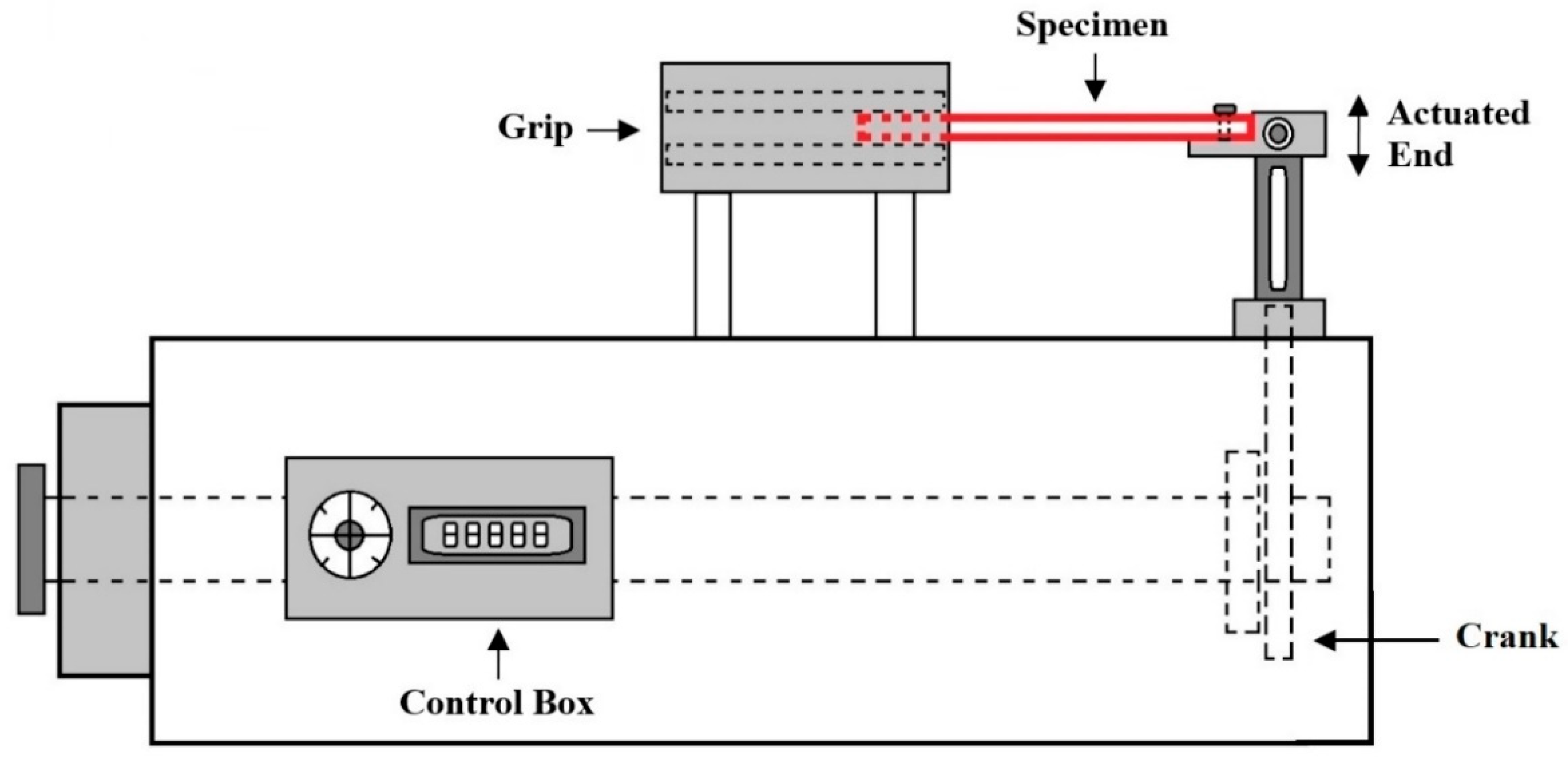
2.1. Fatigue Test

Bench-mounted fatigue bending test rig (Model: LFE–150, Fatigue Dynamics, Walled Lake, MI, USA) is used to perform fully reversed fatigue bending tests. A schematic image of the apparatus is shown in Figure 1. One end of the dog-bone specimen is clamped at the grip section of the machine, and the other end is attached to the actuated end using three screws. The load is set by adjusting a displacement level at the disk connected to the actuated end. The actuation displacement for all the experiments reported in this paper is 10.16 mm. A finite element analysis shows that the maximum longitudinal stress value induced by the 10.16 mm displacement is 432 MPa.

2.2. Material and Specimen Preparation

The SS316 specimens with the composition and properties shown in Table 1 are cut into flat and dog-boned shape (Figure 2) in accordance with ASTM STP566 [14] using a Mitsubishi MV2400S Wire Electronic Discharge Machining System (Tokyo, Japan).
The specimens are heat-treated in the chamber of a Nabertherm GmbH N 7/H furnace (Bahnhofstr, Germany). The chamber is purged with Argon before the heat treatment in order to avoid oxidation. Specimens are heat-treated at 400 °C and 600 °C for 2 h and then allowed to cool down naturally in the furnace atmosphere.

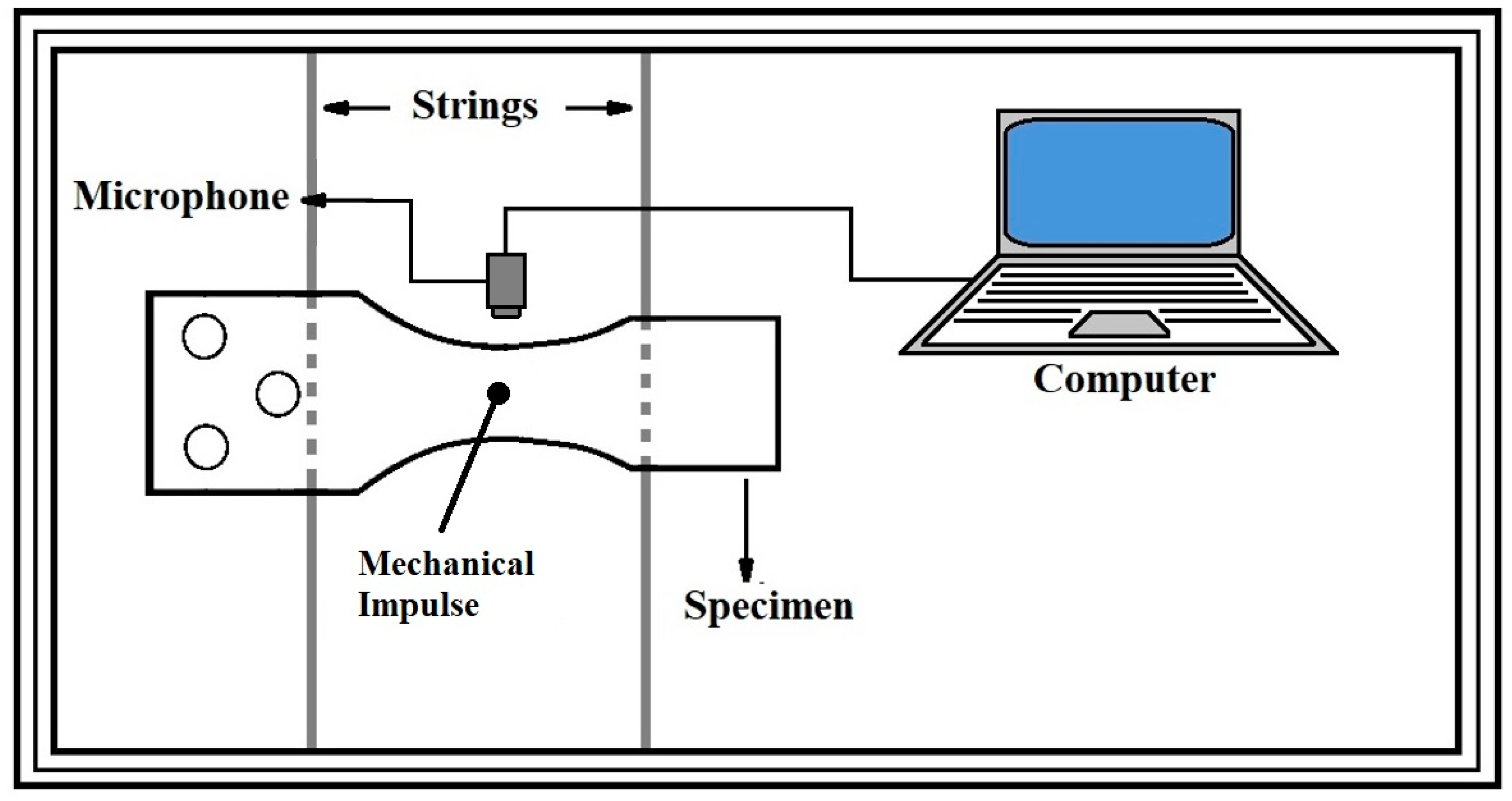
2.3. Impulse Excitation Technique (IET)

To measure the damping of the specimen, the IET device (IMCE, Genk, Belgium) is used. First, the specimen is situated on the two parallel strings, as shown in Figure 3, and tapped with a small hammer. The sound produced is recorded by a microphone connected to the computer. A Resonant Frequency Damping Analyzer (RFDA) software then analyzes the recorded sound by measuring the attenuation and calculate the damping. More detail of the IET is reported in Ref [2].

2.4. Experimental Procedure

We first perform fatigue bending experiments to determine the life of a number of SS316 specimens at several displacement actuation amplitudes. We then conduct a series of experiments in which we interrupt the test at different time intervals, unmount the specimen, place it on the apparatus testing strings (see Figure 3), and measure damping value with IET. Next, we perform another set of fatigue test at the same operating conditions and interrupt the test to perform RHT.

3. Results

In this section, we begin by first presenting the results of three experiments at identical conditions to show the evolution of the damping parameter as a function of the number of cycles at a specific frequency and stress level. We then present the result of the fatigue tests (at the same frequency and stress level) for three different cases at which the tests are interrupted at a different number of cycles, and RHT is conducted. We perform four experiments for each case to accurately investigate the fatigue life extension as a result of each RHT procedure.
Figure 4 presents the evolution of damping value for SS316 specimens tested at the frequency of 20 Hz and stress level of 432 MPa. The results are obtained from four experiments at identical conditions, and the average damping value and the corresponding standard deviation are shown in the figure. The figure shows that at the stress level of 432 MPa, the fatigue life of the specimens is in the range of 96,000 to 105,000 cycles, i.e., low-cycle fatigue.
Referring to Figure 4, damping initially increases due to the increase in the density of dislocation due to hardening (Stage I). The density of dislocations remains nearly constant in Stage II after hardening as the number of cycles increases. Therefore, the damping evolution shows just a slight change in the second stage, as indicated in Figure 4. As shown, in Stage III, damping experiences a rapid rise. This is an indication of the onset of macrocrack initiation and its rapid growth until fracture occurs. Referring to Figure 4, under the conditions tested, macrocrack initiation occurs somewhere between 75,000 and 85,000 cycles.
Given that PSBs are a precursor to fatigue crack initiation, we now explore enhancing fatigue life by annihilating them using RHT at different temperatures. This is achieved by first heat-treating the specimens at 600 °C and holding them for two hours; 600 °C is selected for the RHT because, at this temperature, no phase change occurs in SS316, and the only expected change is the density of dislocations. See Section 1 for further discussion. Additionally, according to published research [15], holding the specimens under RHT for two hours yields satisfactory results. However, the challenge is to determine the most suitable time for interrupting the test and conducting the RHT. Therefore, three different cases presented in Table 2 are considered.

3.1. Case I. RHT at Half-life

Figure 5 presents experimental results conducted with four SS316 specimens subjected to a loading frequency of 20 Hz, and a stress level of 432 MPa, and the average damping and the corresponding standard deviation are shown. Additionally, in Figure 5, the damping result presented in Figure 4 is shown as a red dashed line in order to compare the damping behavior and fatigue life of a specimen with that of a heat-treated one. The solid blue line shows the number of cycles at which the experiment is interrupted and RHT is performed. In this case, the tests are halted at the specimen’s half-life (50k) and the specimens are heat-treated for two hours in an attempt to partially recover some of the accumulated damage by virtue of PSBs annihilation. By comparing the red dashed line and solid black line in Figure 5, it can be seen that by heat-treating the specimen at 600 °C, the life of the specimen is, on average, increased by 24%.
Figure 5 shows that after recovery heat treatment, the damping drops significantly to a value even lower than that of a pristine specimen due to the decrease in density of the pre-existing dislocations and PSBs. Note that dislocations exist in an as-received material due to the manufacturing procedures that contribute to its damping. As described in Section 1, the density of dislocations decreases due to RHT (provided that the specimen is cooled down slowly in the furnace), and, as a result, the measured value of damping is expected to be less than its value before RHT. Specifically, the damping value of a pristine as-received specimen is 0.000066, and that of a fatigued specimen after RHT is about 0.000034. Therefore, according to Figure 5, after RHT at the half-life of a specimen, nearly all the pre-existing PSBs are removed. To verify this, we measured the damping value of a pristine heat-treated specimen and it turned out to be 0.000035. Therefore, we can conclude that the reduction in damping value (see Figure 5) is due to the annihilation of pre-existing dislocations and the dislocations emerge due to plastic deformation.
Figure 5 also shows that damping is increased more rapidly after the RHT, which means that the rate of damage accumulation is increased. This shows that SS316 specimen is embrittled after the recovery heat treatment. According to Chastell and Flewitt [16] and Chen et al. [17], SS316 becomes brittle due to the formation of carbides, which is known to occur at the temperatures range from 600 °C to 950 °C. Additionally, the existence of fewer dislocations, which make the specimen more brittle, can be another reason. As a result, when the load is applied, instead of the movement of dislocations and formation of PSBs, microcracks form and propagate rapidly. The smaller slope of damping after the RHT is indicative of a lesser work-hardening (compared to the beginning of the test). This represents another indication of the brittle behavior of the material.

3.2. Case II. RHT Close to the Crack Initiation

Figure 6 presents the damping results obtained from four identical experiments. The average value of each parameter, along with its standard deviation, is shown in the figure. The tests are conducted at a stress level of 432 MPa and a frequency of 20 Hz, identical to Case I. The damping result of an as-received specimen (Figure 4) is also shown as red dashed line in Figure 6. According to Figure 4, we expect the macrocrack to initiate somewhere between 75,000 and 85,000. Therefore, we heat-treat the specimen at 70,000 cycles where the macrocrack has not been nucleated yet. According to Figure 6, by heat-treating the specimen, its fatigue life is increased by about 30% on average, which shows an improvement compare to case I. In fact, in Case I, after the RHT, it takes the specimen about 60,000 cycles to fracture. For Case II, the number of cycles to failure after the RHT is about 50,000. Therefore, it can be concluded that RHT for Case II (RHT close to crack initiation) is slightly less effective. However, the number of cycles to failure for Case II is more than Case I. This is simply because a longer portion of the specimen’s life has passed, and less life is remaining after the RHT in Case II. Figure 6 shows that, similar to Case I, the damping value goes back to a value less than that of a pristine specimen, which indicates the reduction in the dislocation density. The smaller slope of damping after RHT indicates less work hardening, and therefore the specimen is becoming more brittle in this case as well.

3.3. Case III. RHT after Crack Initiation

Figure 7 denotes the results of the damping evolution plotted versus the number of cycles for four SS316 specimens subjected to the same operating conditions as Cases I and II. The red dashed line in this figure corresponds to the damping result presented in Figure 4. To examine the effect of the RHT after macrocrack initiation, RHT is done at 90,000 cycles where the macrocrack has already been initiated. According to Figure 7, by heat-treating the specimen at 600 °C, the life of the specimen is increased by only 12%, which is lower than the previous cases. Although most of the fatigue life of the specimen is expended, and this case should be more effective than the other two, the results surprisingly show the opposite. To explain this, we need to consider the concept of hot isotropic pressing. According to this concept, in order to remove a void or crack, both heat and high isostatic pressure are needed [18]. According to Atkinson and Davies [19], molecules of a gas inside of the hipping chamber apply pressure on the surface of a specimen and act as hot forging to reduce the surface area of the cracks. Therefore, to reduce a crack surface area, high isostatic pressure is needed along with high temperature since RHT alone cannot be very effective. However, Fergani et al. [20] show that the only effect that RHT imposes, in this case (RHT after crack initiation), is to reduce the residual stress, which has little or no effect on the fatigue crack propagation.

3.4. Recovery Heat Treatment at 400 °C

The experiments presented in Section 3.1 to Section 3.3 for three different cases are repeated for recovery heat treatment at 400 °C. Similar to the previously used RHT, the samples are heated at a chamber filled with Argon up to 400 °C and held for 2 hours. The fatigue life of the heat-treated specimens is presented in Table 3. These results suggest that, for all three cases, the specimens heat-treated at 600 °C show better fatigue resistivity compared to the ones heat-treated at 400 °C.

4. Discussion

Stainless steels can be categorized into five different types according to their microstructure: ferritic, austenitic, martensitic, ferritic–austenitic, and precipitation-hardenable [21]. As-received SS316 is austenite type with less than 0.08 percent carbon content, which is of great interest in the industry due to its excellent corrosion resistance, ductility, toughness, and weldability [21]. There are different phases of stainless steel, and the percentage of these phases depends on the RHT temperature and its duration time. Weiss and Strickler [22] present the time-temperature–transformation (TTT) diagram for SS316 according to which no major phase change is seen in SS316 at temperatures below 900 °C [23]. Additionally, according to [24], heat treatment, even at 1070 °C, does not affect the grain size of the material. Moreover, Kamaria et al. [25] show that the hardness of SS316 remains nearly constant after heat-treatment at 650 °C with the holding time of 2 hours (cooled in the furnace). However, at higher temperatures (above 950 °C) the hardness decreases because of the disappearing of the cellular dendrites’ microstructure [22]. Therefore, at the temperature of 600 °C and below, no major change in the phases and mechanical properties is expected.
Figure 8 depicts the XRD profile of the untreated and heat-treated (at 600 °C) SS316 specimens. The figure shows the same peaks for both specimens, which indicate the existence of γ (austenite) and α′ (martensite) phases. The α’ phase usually exists due to the plastic deformation during the manufacturing process [26]. After heat-treating, the α′ (111) decreases, which is an indication of the alleviation of the non-equilibrium phase in the heat-treated specimen [23], which can cause fatigue life extension. The XRD profile confirms that no significant phase change occurs at the temperatures below 900 °C.
According to Sangid [27], in materials under cyclic loading, two different phases of PSBs and matrix form with different properties. The PSBs are softer than the matrix and most of the plastic deformations tend to accumulate in them [3]. It is believed that crack initiates from the interface of PSBs and matrix. According to Li et al. [11], the strain energy at the interface of PSBs and matrix releases when a specimen is heat-treated. Consequently, dislocation rearrangement occurs and the interface becomes curved [11]. This causes the dislocation dipoles in the PSB to annihilate—as shown in previous sections—resulting in an increase in metal fatigue life. According to the results presented in Section 3, the most effective interval for recovery heat treatment is to employ RHT close to the crack initiation. This is because the specimen has spent a considerable portion of its fatigue life but is still in Stage II (see Section 1) where PSBs form in the bulk and emerge on the free surface as extrusions and intrusions, and that RHT greatly reduces the PSBs. Our results (Figure 7) show that the least effective time for the RHT is after crack initiation, since RHT cannot close a crack without any compression load. The main effect of RHT is to release the residual stress around the tip of the crack [28] and to slow down its propagation rate.
Table 3 represents the results for RHT at 400 °C. Except for Case III, the fatigue life enhancement by both RHT procedures are comparable. However, RHT at 600 °C is more promising since it shows better fatigue life improvement. This is true for all three cases tested, since, at a higher temperature, more energy is provided for the dislocations to move and annihilate and, as a result, reduce the deleterious effect of degradation due to cyclic loading.

5. Conclusions

Fully-reversed fatigue bending tests are performed on flat dog-boned SS316 specimens to study the effect of recovery heat treatment on the fatigue life of the specimens. The specimens are heat-treated at two different temperatures (400 °C and 600 °C) and three different intervals (half-life, close to crack initiation, and after crack initiation). To correlate the effect of each RHT on the density of dislocations and detect the crack initiation moment, damping is measured using IET. The results reveal that two different mechanisms affect the fatigue life of specimens after RHT. They are reduction of the density of PSBs and reduction of the density of dislocation. The reduction of the PSBs has a positive influence on extending fatigue life, while a reduction in the density of dislocation has a negative effect because the material tends to become more brittle. It is shown that compared to RHT at 400 °C, the fatigue life can be extended in all cases examined by heat-treating the specimens at 600 °C. Additionally, it is shown that for RHT at half-life, close to crack initiation, and after crack initiation the fatigue life is enhanced by 24%, 30%, and 12%, respectively. Therefore, RHT close to the onset of crack initiation yields the best results in improving the fatigue life of SS316 specimens.

Author Contributions

Conceptualization A.H. and M.M.K.; Writing-Original draft preparation, A.H.; writing—review and editing, M.M.K.; supervision, M.M.K. All authors have read and agreed to the published version of the manuscript.

Funding

This research received no external funding.

Conflicts of Interest

The authors declare no conflict of interest

References

  1. Haghshenas, A.; Khonsari, M.M. Damage accumulation and crack initiation detection based on the evolution of surface roughness parameters. Int. J. Fatigue 2018, 107, 130–144. [Google Scholar] [CrossRef]
  2. Mortazavi, V.; Haghshenas, A.; Khonsari, M.M.; Bollen, B. Fatigue analysis of metals using daping parameter. Int. J. Fatigue 2016, 91, 124–135. [Google Scholar] [CrossRef]
  3. Mughrabi, H. The cyclic hardening and saturation behaviour of copper single crystals. Mater. Sci. Eng. 1978, 33, 207–223. [Google Scholar] [CrossRef]
  4. Man, J.; Obrtlík, K.; Polák, J. Extrusions and intrusions in fatigued metals. Part 1. State of the art and history. Philos. Mag. 2009, 89, 1295–1336. [Google Scholar] [CrossRef]
  5. Gupta, S.; Barrios, A.; England, N.; Pierron, O.N. Improved very high cycle bending fatigue behavior of Ni microbeams with Au coatings. Acta Mater. 2018, 161, 444–455. [Google Scholar] [CrossRef]
  6. Hackel, L.; Rankin, J.; Racanellia, T.; Mills, T.; Campbell, J.H. Laser peening to improve fatigue strength and lifetime of critical components. Procedia Eng. 2015, 133, 545–555. [Google Scholar] [CrossRef]
  7. Haghshenas, A.; Khonsari, M.M. On the removal of extrusions and intrusions via repolishing to improve metal fatigue life. Theor. Appl. Fract. Mech. 2019, 103, 102248. [Google Scholar] [CrossRef]
  8. Zhang, B.; Haghshenas, A.; Zhang, X.; Zhao, J.; Shao, S.; Khonsari, M.M.; Guo, S.; Meng, W.J. On the failure mechanisms of Cr-coated 316 stainless steel in bending fatigue tests. Int. J. Fatigue 2020, 139, 105733. [Google Scholar] [CrossRef]
  9. Steel Heat Treatment Handbook-2 Volume Set; Totten, G.E. (Ed.) CRC Press: Boca Raton, FL, USA, 2006. [Google Scholar]
  10. Yadollahi, A.; Shamsaei, N.; Thompson, S.M.; Elwany, A.; Bian, L. Effects of building orientation and heat treatment on fatigue behavior of selective laser melted 17-4 PH stainless steel. Int. J. Fatigue 2017, 94, 218–235. [Google Scholar] [CrossRef]
  11. Li §, S.X.; Li, M.Y.; Zhu, R.; Chao, Y.S. Annihilation of persistent slip bands and its effect on the fatigue life of copper single crystals. Philos. Mag. 2004, 84, 3323–3334. [Google Scholar] [CrossRef]
  12. Eshelby, J.D. Dislocations as a Cause of Mechanical Damping in Metals. Proceedings of the Royal Society of London. Ser. A Math. Phys. Sci. 1949, 197, 396–416. [Google Scholar]
  13. Hoyos, J.J.; Ghilarducci, A.A.; Mari, D. Evaluation of dislocation density and interstitial carbon content in quenched and tempered steel by internal friction. Mater. Sci. Eng. A 2015, 640, 460–464. [Google Scholar] [CrossRef]
  14. Swanson, S.R. (Ed.) Handbook of Fatigue Testing; American Society for Testing and Materials: West Conshohocken, PA, USA, 1974. [Google Scholar]
  15. Montero Sistiaga, M.; Nardone, S.; Hautfenne, C.; Van Humbeeck, J. Effect of heat treatment of 316L stainless steel produced by selective laser melting (SLM). In Proceedings of the 27th Annual International Solid Freeform Fabrication Symposium—An Additive Manufacturing Conference, Austin, TX, USA, 8–10 July 2016; AT&T Conference Center, The University of Texas: Austin, TX, USA, 2016; pp. 558–565. [Google Scholar]
  16. Chastell, J.D.; Flewitt, P.E.J. The formation of the σ phase during long term high temperature creep of type 316 austenitic stainless steel. Mater. Sci. Eng. 1979, 38, 153–162. [Google Scholar] [CrossRef]
  17. Chen, X.; Li, J.; Cheng, X.; Wang, H.; Huang, Z. Effect of heat treatment on microstructure, mechanical and corrosion properties of austenitic stainless steel 316L using arc additive manufacturing. Mater. Sci. Eng. A 2018, 715, 307–314. [Google Scholar] [CrossRef]
  18. Harrison, N.J.; Todd, I.; Mumtaz, K. Reduction of micro-cracking in nickel superalloys processed by Selective Laser Melting: A fundamental alloy design approach. Acta Mater. 2015, 94, 59–68. [Google Scholar] [CrossRef] [Green Version]
  19. Atkinson, V.H.; Davies, S. Fundamental aspects of hot isostatic pressing: An overview. Metall. Mater. Trans. A 2000, 31, 2981–3000. [Google Scholar] [CrossRef]
  20. Fergani, O.; Bratli Wold, A.; Berto, F.; Brotan, V.; Bambach, M. Study of the effect of heat treatment on fatigue crack growth behaviour of 316L stainless steel produced by selective laser melting. Fatigue Fract. Eng. Mater. Struct. 2018, 41, 1102–1119. [Google Scholar] [CrossRef]
  21. George, E. Totten, Steel Heat Treatment, Metallurgy and Technology; Taylor & Francis Group: Oxfordshire, UK, 2004. [Google Scholar]
  22. Weiss, B.F.; Stickler, R. Phase instabilities during high temperature exposure of 316 austenitic stainless steel. Metall. Mater. Trans. B. 1972, 3, 851–866. [Google Scholar] [CrossRef]
  23. Ettefagh, H.; Guo, S. Electrochemical behavior of AISI316L stainless steel parts produced by laser-based powder bed fusion process and the effect of post annealing process. Addit. Manuf. 2018, 22, 153–156. [Google Scholar]
  24. Blinn, B.; Klein, M.; Gläßner, C.; Smaga, M.; Aurich, J.C.; Beck, T. An Investigation of the Microstructure and Fatigue Behavior of Additively Manufactured AISI 316L Stainless Steel with Regard to the Influence of Heat Treatment. Metals 2018, 8, 220. [Google Scholar] [CrossRef] [Green Version]
  25. Kamariah, M.S.I.N.; Harun, W.S.W.; Khalil, N.Z.; Ahmad, F.; Ismail, M.H.; Sharif, S. Effect of heat treatment on mechanical properties and microstructure of selective laser melting 316L stainless steel. IOP Conf. Ser. Mater. Sci. Eng. 2017, 257, 012021. [Google Scholar] [CrossRef]
  26. Jinlong, L.; Meng, Y.; Miura, H.; Tongxiang, L. The effect of surface enriched chromium and grain refinement by ball milling on corrosion resistance of 316L stainless steel. Mater. Res. Bull. 2017, 91, 91–97. [Google Scholar] [CrossRef]
  27. Sangid, M.D. The physics of fatigue crack initiation. Int. J. Fatigue 2013, 57, 58–72. [Google Scholar] [CrossRef]
  28. Farahani, M.; Sattari-Far, I. Effects of residual stresses on crack-tip constraints. Sci. Iran. 2011, 18, 1267–1276. [Google Scholar] [CrossRef] [Green Version]
Figure 1. Fatigue bending test rig.
Metals 10 01290 g001
Figure 2. Schematic of the dog-bone flat SS316 specimen (all dimensions are in millimeters).
Metals 10 01290 g002
Figure 3. Schematic of the damping measurement setup.
Metals 10 01290 g003
Figure 4. Evolution of damping versus the number of cycles for an SS316 specimen at the frequency of 20 Hz and stress level of 432 MPa.
Metals 10 01290 g004
Figure 5. Evolution of damping for an SS316 specimen versus the number of cycles with the load frequency of 20 Hz and stress amplitude of 432 MPa halted and heat-treated at the temperature of 600 °C, at its half-life (50 k cycles). Dashed line results are the damping values of an untreated (as-received) specimen as a benchmark.
Metals 10 01290 g005
Figure 6. Evolution of damping for an SS316 specimen versus the number of cycles with the load frequency of 20 Hz and stress amplitude of 432 MPa halted and heat-treated at the temperature of 600 °C, close to the crack initiation (70 k cycles). Dashed line results are the damping values of an untreated (as-received) specimen as a benchmark.
Metals 10 01290 g006
Figure 7. Evolution of damping for an SS316 specimen versus the number of cycles with the load frequency of 20 Hz and stress amplitude of 432 MPa halted and heat-treated at the temperature of 600 °C, after crack initiation (90 k). Dashed line results are the damping values of an untreated (as-received) specimen as a benchmark.
Metals 10 01290 g007
Figure 8. XRD profile of the SS316 (a) untreated and (b) heat-treated specimens.
Metals 10 01290 g008
Table 1. Properties and compositions of SS316.
CCrCuMnMoNNiPSFeYield StrengthUltimate Strength
SS 3160.015%16.7695%0.4915%1.6285%2.033%0.0486%10.015%0.0345%0.0158%Bal.290 MPa616 MPa
Table 2. Different cases of recovery heat-treatmnt (RHT) SS316 specimens at different intervals.
ConditionComments
Case I600 °C, 2 hRHT at half-life (50 k)
Case II600 °C, 2 hRHT close to the crack initiation (70 k)
Case III600 °C, 2 hRHT after crack initiation (90 k)
Table 3. Different cases of RHT SS316 specimens at different intervals.
ConditionCommentsExpected Fatigue Life
(Average)
Actual Fatigue LifeFatigue Life Extension
Case I400 °C
2 h
RHT at half-life (50 k)100,500116,50016%
Case II400 °C
2 h
RHT close to the crack initiation (70 k)100,500122,30022%
Case III400 °C
2 h
RHT after crack initiation (90 k)100,500106,7006%

