Effect of Modification with Different Contents of Sb and Sr on the Thermal Conductivity of Hypoeutectic Al-Si Alloy


Abstract
1. Introduction
2. Materials and Methods
3. Results
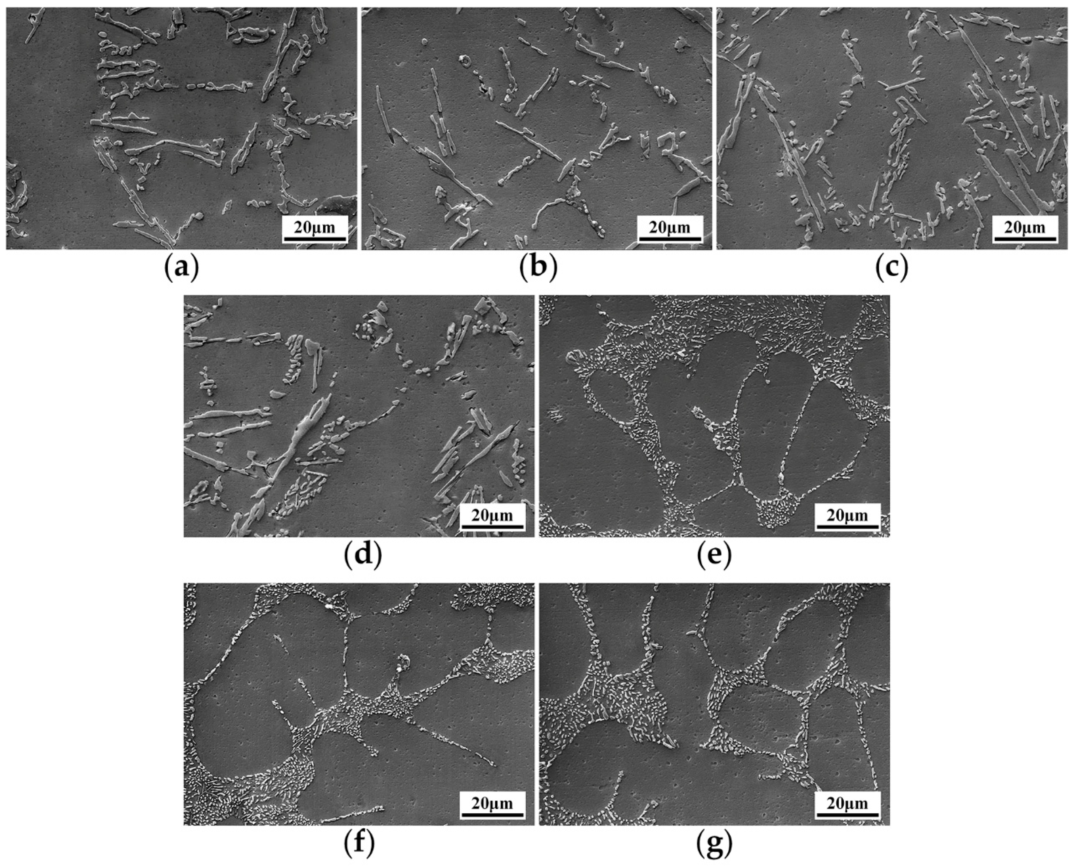
3.1. Microstructure
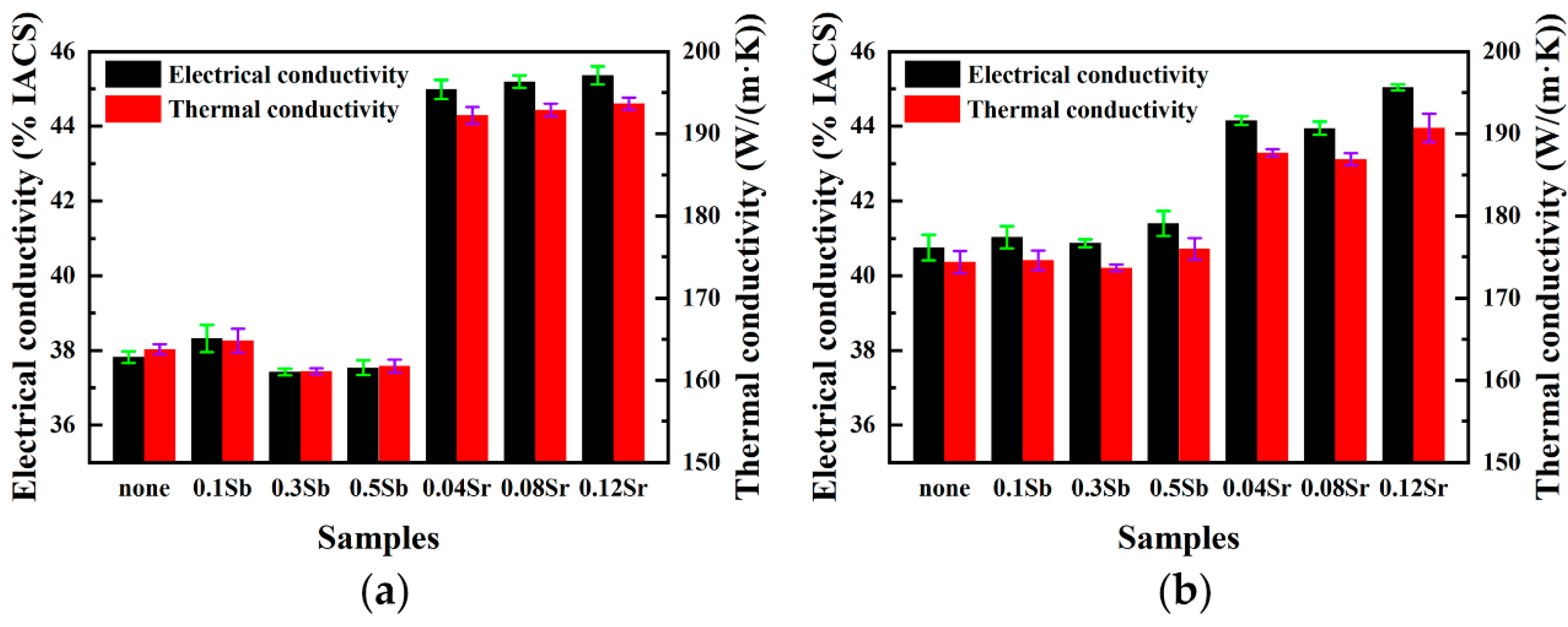
3.2. Thermal and Electrical Conductivities
4. Discussion
5. Conclusions
Author Contributions
Funding
Conflicts of Interest
References
- Abdollahi, A.; Gruzleski, J.E. An evaluation of calcium as a eutectic modifier in A357 alloy. Int. J. Cast Met. Res. 1998, 11, 145–155. [Google Scholar] [CrossRef]
- Cui, X.; Cui, H.; Wu, Y.; Liu, X. The improvement of electrical conductivity of hypoeutectic Al-Si alloys achieved by composite melt treatment. J. Alloy. Compd. 2019, 788, 1322–1328. [Google Scholar] [CrossRef]
- Li, K.; Li, W.; Zhang, G.; Zhu, W.; Zheng, F.; Zhang, D.; Wang, M. Effects of Si phase refinement on the plasma electrolytic oxidation of eutectic Al-Si alloy. J. Alloy. Compd. 2019, 790, 650–656. [Google Scholar] [CrossRef]
- Shaji, M.C.; Ravikumar, K.K.; Ravi, M.; Sukumaran, K. Development of a high strength cast aluminium alloy for possible automotive applications. Mater. Sci. Forum 2013, 765, 54–58. [Google Scholar] [CrossRef]
- Rauta, V.; Cingi, C.; Orkas, J. Effect of annealing and metallurgical treatments on thermal conductivity of aluminium alloys. Int. J. Met. 2016, 10, 157–171. [Google Scholar] [CrossRef]
- Stadler, F.; Antrekowitsch, H.; Fragner, W.; Kaufmann, H.; Pinatel, E.R.; Uggowitzer, P.J. The effect of main alloying elements on the physical properties of Al–Si foundry alloys. Mater. Sci. Eng. A 2013, 560, 481–491. [Google Scholar] [CrossRef]
- Cui, X.; Wu, Y.; Liu, X.; Zhao, Q.; Zhang, G. Effects of grain refinement and boron treatment on electrical conductivity and mechanical properties of AA1070 aluminum. Mater. Des. 2015, 86, 397–403. [Google Scholar] [CrossRef]
- Cui, X.; Wu, Y.; Zhang, G.; Liu, Y.; Liu, X. Study on the improvement of electrical conductivity and mechanical properties of low alloying electrical aluminum alloys. Compos. Part B Eng. 2017, 110, 381–387. [Google Scholar] [CrossRef]
- Khaliq, A.; Rhamdhani, M.A.; Brooks, G.A.; Grandfield, J.F. Removal of vanadium from molten aluminum—Part II. Kinetic analysis and mechanism of VB2 formation. Metall. Mater. Trans. B 2014, 45, 769–783. [Google Scholar] [CrossRef]
- Cui, X.; Wu, Y.; Cui, H.; Zhang, G.; Zhou, B.; Liu, X. The improvement of boron treatment efficiency and electrical conductivity of AA1070Al achieved by trace Ti assistant. J. Alloy. Compd. 2018, 735, 62–67. [Google Scholar] [CrossRef]
- Mulazimoglu, M.H.; Drew, R.A.L.; Gruzelski, J.E. Electrical conductivity of aluminium-rich Al-Si-Mg alloys. J. Mater. Sci. Lett. 1989, 8, 297–300. [Google Scholar] [CrossRef]
- Mulazimoglu, M.H.; Drew, R.A.L.; Gruzleski, J.E. The electrical conductivity of cast Al−Si alloys in the range 2 to 12.6 wt pct silicon. Metall. Trans. A 1989, 20, 383–389. [Google Scholar] [CrossRef]
- Narayan Prabhu, K.; Ravishankar, B.N. Effect of modification melt treatment on casting/chill interfacial heat transfer and electrical conductivity of Al–13% Si alloy. Mater. Sci. Eng. A 2003, 360, 293–298. [Google Scholar] [CrossRef]
- Lumley, R.N.; Polmear, I.J.; Groot, H.; Ferrier, J. Thermal characteristics of heat-treated aluminum high-pressure die-castings. Scripta Materialia 2008, 58, 1006–1009. [Google Scholar] [CrossRef]
- Choi, S.W.; Cho, H.S.; Kang, C.S.; Kumai, S. Precipitation dependence of thermal properties for Al–Si–Mg–Cu–(Ti) alloy with various heat treatment. J. Alloy. Compd. 2015, 647, 1091–1097. [Google Scholar] [CrossRef]
- Lados, D.A.; Apelian, D.; Wang, L. Solution treatment effects on microstructure and mechanical properties of Al-(1 to 13 pct)Si-Mg cast alloys. Metall. Mater. Trans. B 2010, 42, 171–180. [Google Scholar] [CrossRef]
- Vandersluis, E.; Ravindran, C. Effects of solution heat treatment time on the as-quenched microstructure, hardness and electrical conductivity of B319 aluminum alloy. J. Alloy. Compd. 2020, 838. [Google Scholar] [CrossRef]
- Tiedje, N.S.; Taylor, J.A.; Easton, M.A. A new multi-zone model for porosity distribution in Al–Si alloy castings. Acta Mater. 2013, 61, 3037–3049. [Google Scholar] [CrossRef]
- Barrirero, J.; Li, J.; Engstler, M.; Ghafoor, N.; Schumacher, P.; Odén, M.; Mücklich, F. Cluster formation at the Si/liquid interface in Sr and Na modified Al–Si alloys. Scripta Mater. 2016, 117, 16–19. [Google Scholar] [CrossRef]
- Li, J.H.; Wang, X.D.; Ludwig, T.H.; Tsunekawa, Y.; Arnberg, L.; Jiang, J.Z.; Schumacher, P. Modification of eutectic Si in Al–Si alloys with Eu addition. Acta Mater. 2015, 84, 153–163. [Google Scholar] [CrossRef]
- Rao, J.; Zhang, J.; Liu, R.; Zheng, J.; Yin, D. Modification of eutectic Si and the microstructure in an Al-7Si alloy with barium addition. Mater. Sci. Eng. A 2018, 728, 72–79. [Google Scholar] [CrossRef]
- Li, B.; Wang, H.; Jie, J.; Wei, Z. Effects of yttrium and heat treatment on the microstructure and tensile properties of Al–7.5 Si–0.5 Mg alloy. Mater. Des. 2011, 32, 1617–1622. [Google Scholar] [CrossRef]
- Farahany, S.; Ourdjini, A.; Idrsi, M.H.; Shabestari, S.G. Evaluation of the effect of Bi, Sb, Sr and cooling condition on eutectic phases in an Al–Si–Cu alloy (ADC12) by in situ thermal analysis. Thermochimica Acta 2013, 559, 59–68. [Google Scholar] [CrossRef]
- Darlapudi, A.; McDonald, S.D.; Terzi, S.; Prasad, A.; Felberbaum, M.; StJohn, D.H. The influence of ternary alloying elements on the Al–Si eutectic microstructure and the Si morphology. J. Cryst. Growth 2016, 433, 63–73. [Google Scholar] [CrossRef]
- Olafsson, P.; Sandstrom, R.; Karlsson, Å. Comparison of experimental, calculated and observed values for electrical and thermal conductivity of aluminium alloys. J. Mater. Sci. 1997, 32, 4383–4390. [Google Scholar] [CrossRef]
- Lumley, R.N.; Deeva, N.; Larsen, R.; Gembarovic, J.; Freeman, J. The role of alloy composition and T7 heat treatment in enhancing thermal conductivity of aluminum high pressure diecastings. Metall. Mater. Trans. A Phys. Metall. Mater. Sci. 2013, 44, 1074–1086. [Google Scholar] [CrossRef]
- Cho, Y.H.; Kim, H.W.; Lee, J.M.; Kim, M.S. A new approach to the design of a low Si-added Al-Si casting alloy for optimising thermal conductivity and fluidity. J. Mater. Sci. 2015, 50, 7271–7281. [Google Scholar] [CrossRef]
- Vandersluis, E.; Lombardi, A.; Ravindran, C.; Bois-Brochu, A.; Chiesa, F.; MacKay, R. Factors influencing thermal conductivity and mechanical properties in 319 Al alloy cylinder heads. Mater. Sci. Eng. A 2015, 648, 401–411. [Google Scholar] [CrossRef]
- Dinnis, C.M.; Taylor, J.A.; Dahle, A.K. As-cast morphology of iron-intermetallics in Al–Si foundry alloys. Scripta Materialia 2005, 53, 955–958. [Google Scholar] [CrossRef]
- Faraji, M.; Katgerman, L. Distribution of trace elements in a modified and grain refined aluminium–silicon hypoeutectic alloy. Micron 2010, 41, 554–559. [Google Scholar] [CrossRef]
- Simensen, C.J.; Nielsen, Ø.; Hillion, F.; Voje, J. NanoSIMS Analysis of trace element segregation during the Al-Si eutectic reaction. Metall. Mater. Trans. A 2007, 38, 1448–1451. [Google Scholar] [CrossRef]
- Lu, S.Z.; Hellawell, A. The mechanism of silicon modification in aluminum-silicon alloys: Impurity induced twinning. Metall. Trans. A 1987, 18, 1721–1733. [Google Scholar] [CrossRef]
- Nogita, K.; Yasuda, H.; Yoshida, K.; Uesugi, K.; Takeuchi, A.; Suzuki, Y.; Dahle, A.K. Determination of strontium segregation in modified hypoeutectic Al–Si alloy by micro X-ray fluorescence analysis. Scripta Materialia 2006, 55, 787–790. [Google Scholar] [CrossRef]
- Nogita, K.; Yasuda, H.; Yoshiya, M.; McDonald, S.D.; Uesugi, K.; Takeuchi, A.; Suzuki, Y. The role of trace element segregation in the eutectic modification of hypoeutectic Al–Si alloys. J. Alloy. Compd. 2010, 489, 415–420. [Google Scholar] [CrossRef]
- Lu, S.-Z.; Hellawell, A. Growth mechanisms of silicon in Al-Si alloys. J. Cryst. Growth 1985, 73, 316–328. [Google Scholar] [CrossRef]
- Hansen, S.C.; Loper, C.R. Effect of antimony on the phase equilibrium of binary Al-Si alloys. Calphad 2000, 24, 339–352. [Google Scholar] [CrossRef]
- Xiufang, B.; Weimin, W.; Jingyu, Q. Liquid structure of Al–12.5% Si alloy modified by antimony. Mater. Charact. 2001, 46, 25–29. [Google Scholar] [CrossRef]
- Gustafsson, G.; Thorvaldsson, T.; Dunlop, G.L. The influence of Fe and Cr on the microstructure of cast Al-Si-Mg alloys. Metall. Trans. A 1986, 17, 45–52. [Google Scholar] [CrossRef]
- Mohamed, A.M.A.; Samuel, A.M.; Samuel, F.H.; Doty, H.W. Influence of additives on the microstructure and tensile properties of near-eutectic Al–10.8%Si cast alloy. Mater. Des. 2009, 30, 3943–3957. [Google Scholar] [CrossRef]
- Zhao, Q.; Qian, Z.; Cui, X.; Wu, Y.; Liu, X. Optimizing microstructures of dilute Al–Fe–Si alloys designed with enhanced electrical conductivity and tensile strength. J. Alloy. Compd. 2015, 650, 768–776. [Google Scholar] [CrossRef]
- Hou, J.P.; Li, R.; Wang, Q.; Yu, H.Y.; Zhang, Z.J.; Chen, Q.Y.; Ma, H.; Wu, X.M.; Li, X.W.; Zhang, Z.F.; et al. Breaking the trade-off relation of strength and electrical conductivity in pure Al wire by controlling texture and grain boundary. J. Alloy. Compd. 2018, 769, 96–109. [Google Scholar] [CrossRef]
- Karabay, S. Modification of AA-6201 alloy for manufacturing of high conductivity and extra high conductivity wires with property of high tensile stress after artificial aging heat treatment for all-aluminium alloy conductors. Mater. Des. 2006, 27, 821–832. [Google Scholar] [CrossRef]


| Alloy | Si | Fe | Cu | Mg | Mn | Ti | Sb | Sr | Al |
|---|---|---|---|---|---|---|---|---|---|
| Al-8Si | 8.06 | 0.20 | 0.004 | 0.001 | 0.004 | 0.002 | - | - | Bal. |
| Al-8Si-0.1Sb | 7.85 | 0.22 | 0.004 | 0.002 | 0.005 | 0.002 | 0.09 | - | Bal. |
| Al-8Si-0.3Sb | 7.82 | 0.21 | 0.004 | 0.001 | 0.003 | 0.001 | 0.27 | - | Bal. |
| Al-8Si-0.5Sb | 7.85 | 0.21 | 0.004 | 0.001 | 0.003 | 0.002 | 0.46 | - | Bal. |
| Al-8Si-0.04Sr | 8.04 | 0.21 | 0.004 | 0.001 | 0.003 | 0.001 | - | 0.033 | Bal. |
| Al-8Si-0.08Sr | 7.98 | 0.22 | 0.004 | 0.001 | 0.003 | 0.001 | - | 0.072 | Bal. |
| Al-8Si-1.2Sr | 8.09 | 0.23 | 0.004 | 0.001 | 0.003 | 0.001 | - | 0.108 | Bal. |
| Sample State | Average Length (µm) | Average Width (µm) | Average Size (µm) | Aspect Ratio | σ (% IACS) | T (°C) | λ (W/(m·K)) |
|---|---|---|---|---|---|---|---|
| Unmodified | 9.81 | 2.56 | 6.19 | 3.83 | 37.8 | 29.9 | 163.8 |
| 0.1Sb | 8.14 | 2.04 | 5.09 | 3.98 | 38.3 | 29.9 | 164.9 |
| 0.3Sb | 7.96 | 1.71 | 4.84 | 4.65 | 37.4 | 29.9 | 161.1 |
| 0.5Sb | 9.61 | 1.92 | 5.77 | 5.01 | 37.5 | 29.9 | 161.7 |
| Unmodified + T6 | 7.73 | 1.87 | 4.80 | 4.13 | 40.8 | 27.9 | 174.4 |
| 0.1Sb + T6 | 7.47 | 1.81 | 4.64 | 4.14 | 41.0 | 27.9 | 174.6 |
| 0.3Sb + T6 | 7.78 | 1.91 | 4.85 | 4.07 | 40.9 | 27.9 | 173.7 |
| 0.5Sb + T6 | 7.11 | 1.73 | 4.42 | 4.11 | 41.4 | 27.9 | 175.0 |
| 0.04Sr | - | 0.94 | - | - | 45.0 | 29.9 | 192.3 |
| 0.08Sr | - | 0.76 | - | - | 45.2 | 29.9 | 192.9 |
| 0.12Sr | - | 0.65 | - | - | 45.4 | 29.9 | 193.7 |
| 0.04Sr + T6 | - | 1.73 | - | - | 44.2 | 27.9 | 187.7 |
| 0.08Sr + T6 | - | 1.80 | - | - | 43.9 | 27.9 | 186.9 |
| 0.12Sr + T6 | - | 1.64 | - | - | 45.0 | 27.9 | 190.7 |
Publisher’s Note: MDPI stays neutral with regard to jurisdictional claims in published maps and institutional affiliations. |
© 2020 by the authors. Licensee MDPI, Basel, Switzerland. This article is an open access article distributed under the terms and conditions of the Creative Commons Attribution (CC BY) license (http://creativecommons.org/licenses/by/4.0/).
Share and Cite
Guo, J.; Guan, Z.-P.; Yan, R.-F.; Ma, P.-K.; Wang, M.-H.; Zhao, P.; Wang, J.-G. Effect of Modification with Different Contents of Sb and Sr on the Thermal Conductivity of Hypoeutectic Al-Si Alloy. Metals 2020, 10, 1637. https://doi.org/10.3390/met10121637
Guo J, Guan Z-P, Yan R-F, Ma P-K, Wang M-H, Zhao P, Wang J-G. Effect of Modification with Different Contents of Sb and Sr on the Thermal Conductivity of Hypoeutectic Al-Si Alloy. Metals. 2020; 10(12):1637. https://doi.org/10.3390/met10121637
Chicago/Turabian StyleGuo, Jin, Zhi-Ping Guan, Rui-Fang Yan, Pin-Kui Ma, Ming-Hui Wang, Po Zhao, and Jin-Guo Wang. 2020. "Effect of Modification with Different Contents of Sb and Sr on the Thermal Conductivity of Hypoeutectic Al-Si Alloy" Metals 10, no. 12: 1637. https://doi.org/10.3390/met10121637
APA StyleGuo, J., Guan, Z.-P., Yan, R.-F., Ma, P.-K., Wang, M.-H., Zhao, P., & Wang, J.-G. (2020). Effect of Modification with Different Contents of Sb and Sr on the Thermal Conductivity of Hypoeutectic Al-Si Alloy. Metals, 10(12), 1637. https://doi.org/10.3390/met10121637