Article

Effective Casting Technique of Nano-Particles Alloyed Austenitic Stainless Steel

1
Institute of Metals and Technology, Lepi pot 11, 1000 Ljubljana, Slovenia
2
Jožef Stefan International Postgraduate School, Jamova cesta 39, 1000 Ljubljana, Slovenia
*
Author to whom correspondence should be addressed.
Metals 2020, 10(10), 1287; https://doi.org/10.3390/met10101287
Submission received: 7 September 2020 / Revised: 22 September 2020 / Accepted: 23 September 2020 / Published: 25 September 2020

Abstract

:
In recent decades, considerable efforts have been made in the production of steel and the modification of its microstructure on the nano-scale in order to improve its mechanical properties. One possibility is through nano-particles incorporation and reinforcement. While typical production methods for Metal Matrix nano-Composites (MMnCs) are difficult and expensive, the main drawback of the casting method is the agglomeration of the nano-particles and a poor interface between the nano-particles and the metal matrix. Therefore, the aim of this study was to investigate the potential of adding nano-particles as reinforcement elements through the conventional liquid-metal casting process. The investigation was focused on the various approaches to the modification and addition of nano-particles in the melt, as well as the influence of particle concentration and size on their homogeneity and distribution within the steel matrix. The results show that also in the case of the conventional casting process, it is possible to produce a reinforced steel-matrix nano-composite with a homogeneous distribution of the Al2O3 nano-particles in the matrix. However, in order to obtain a homogeneous distribution of nano-particles in the steel matrix, a dispersion agent is required.

1. Introduction

Significant efforts have been made in developing ways to produce ceramic particulate-reinforced metal-matrix composites (MMCs). However, they are mostly made in an expensive way by using powder metallurgy, ball milling, or infiltration techniques [1]. The efforts to produce high-performance materials with very high strength are directed toward the use in the specialized aerospace, automotive, and wear industries [2]. The production methods for MMCs can be categorized into two major groups: ex situ and in situ. The ex situ synthesis route consists of adding nano-reinforcements to the liquid or powdered metal, while in situ processes refer to those methods leading to the generation of ceramic nano-compounds or particles by reaction during processing (a solid–solid, solid–liquid, liquid–liquid, or solid–gas), for example by using reactive gases [3]. As-synthesized reinforcements in the form of particulates, such as TiC, TiB2, WC, and TiCN, can be added to the steel matrix by using powder metallurgy, for example. Hussainova [4] reported the successful incorporation of a low and high volume fraction of particulate ceramic reinforcements in the steel matrix and the formation of a dense composite material by optimizing the sintering parameters. However, powder metallurgy and sintering have certain limitations, including high costs, porosity, and process complexity, as well as parts size and design restrictions [5]. Liquid-based processes, on the other hand, are much more flexible and cost-effective, especially when it comes to mass production [6].
Liquid-phase processing routes used to produce steel Metal Matrix nano-Composites (MMnCs) include conventional casting, liquid infiltration, squeeze casting and spray co-deposition [7]. For the large-scale production of metal matrix nano-composites, the main problem to face is the low wettability of ceramic nano-particles, which greatly limits the preparation of MMnCs by conventional casting processes. The low wettability and high surface tension of nano-particles result in the inhomogeneous distribution of particles within the matrix [3]. A casting route in which the particles are stirred-in is highly desirable. During casting, the metal is heated to its molten state; then, reinforcements are added and stirred to avoid the settling of reinforcements, followed by casting into a mold. The cooling rate of the casting significantly influences the distribution of reinforcements in the metal matrix [7]. In general, using only stirring, a homogeneous dispersion can be obtained for micro-sized particles, but not for nano-sized particles, which immediately tend to agglomerate due to strong interfacial and van der Waals forces [8]. For most of the particle-reinforced MMCs, the size of the reinforcing particles ranges from several to tens of microns, normally resulting in a considerable reduction in ductility and toughness. In order to enhance the mechanical properties, the particle size needs to be reduced below the micrometer range [9]. The reduced size of the reinforcement phase down to the nano-scale exerts interactions of particles with dislocations, which become of significant importance and, when added to other strengthening effects typically found in conventional MMCs, results in a remarkable improvement of the physical and mechanical properties, e.g., tensile and compressive strength, toughness, creep, notch and wear resistance, density, thermal expansion, etc. [3]. In general, steel MMnCs have demonstrated good mechanical, physical, and wear properties in comparison to conventional steel [10]. However, for the optimal exploitation of the strengthening potential, a homogeneous distribution of reinforcing nano-particles in the metal matrix is required, which needs to be obtained through a fast, efficient, and cost-effective process.
The aim of this work was to investigate the possibilities of homogeneous nano-particle distribution and reinforcement of the steel matrix using a liquid-based processing route. The research was focused on various approaches to the production, modification, and addition of nano-particles into a stainless steel (AISI 316L type) matrix during casting. Furthermore, the influence of concentration, size, and surface modification of nano-particles on the distribution homogeneity was investigated.

2. Materials and Methods

2.1. Materials

The material used in this investigation as a reference and starting base material was commercial austenitic stainless steel AISI 316L with the chemical composition given in Table 1.
As a reinforcement, commercial ceramic Al2O3 nano-particles with a nominal mean particle size of 50 and 500 nm were selected, which were delivered from the company US Research Nanomaterials, Inc. (Houston, TX, USA).

2.2. Casting Method

For all experiments, a batch of commercial AISI 316L austenitic stainless steel was first melted under normal atmospheric conditions using a 20-kg capacity medium-frequency induction furnace. After melting, different techniques of nano-particles addition were employed and modified melt cast into 2 kg or 8 kg ingots. After casting, small 2 kg ingots were investigated in the as-cast conditions, and larger 8 kg ingots were subjected to hot rolling performed in 9 passes. The ingots’ starting temperature for hot rolling was 1150 °C and dropped to 980–1000 °C after the last pass. Then, the hot-rolled ingots were left to cool in air to room temperature. The deformation rate at each rolling pass was 12%, resulting in the overall deformation rate of about 300%.
The initial (as-cast) experiments were aimed at investigating the influence of different nano-particles addition methods, particle sizes and particle concentrations (0.5, 1.0 and 2.5 wt %) on their distribution within the austenitic stainless steel matrix. Different approaches in terms of nano-particles addition into the melt were taken during conventional ingot casting. The methods of particle addition were the submerging method (Figure 1a), pouring-over method (Figure 1b), and the method of sealed tube insertion into the melt flow during casting (Figure 1c). In the first case, nano-particles of the adequate quantity were encapsulated in a ferritic steel tube ((wt %): 0.05% C, 0.30% Si, 0.62% Mn, 16.2% Cr, 0.17% Ni, 0.18% Cu, Fe base), and the tube was submerged into the melt. For the pouring-over method, nano-particles were wrapped into the Al foil, placed on the bottom of the mold, and the melt was poured over it. The final method included nano-particles sealed into the steel or Al tube, which was placed into the melt flow to dissolve and melt completely. The tubes had a length of 400 mm, outer diameter of 12 mm, and wall thickness of 0.4 mm. A detailed description of the casting methods used is given in Table 2. The final goal was to find the best incorporation method, size, and concentration of nano-particles (Table 2) to achieve a uniform distribution of the reinforcement particles throughout the whole ingot. Therefore, 2 kg as-cast ingots were first investigated, and based on the results, a final set of experiments also involving use of CaSi de-oxidant (dispersion agent) and particle activation with oxygen plasma was conducted, involving 8 kg ingots subjected to hot rolling after casting.

2.3. Thermodynamic Calculation with ThermoCalc Software

In order to analyze the phases formation, distribution, and stability during solidification, as well as possible interactions between Al2O3 nano-particles and the stainless steel matrix, simulating thermodynamic calculations were performed using the ThermoCalc software (Thermo-Calc 2017a, Stockholm, Sweden). The database used was TCFE8-TCS Steels/Fe-Alloys [11], with the nano-particles being simulated by adding aluminum and oxygen. The purpose was to get an insight into the stability of the added nano-particles and melt solidification process.

2.4. Microstructure Characterization

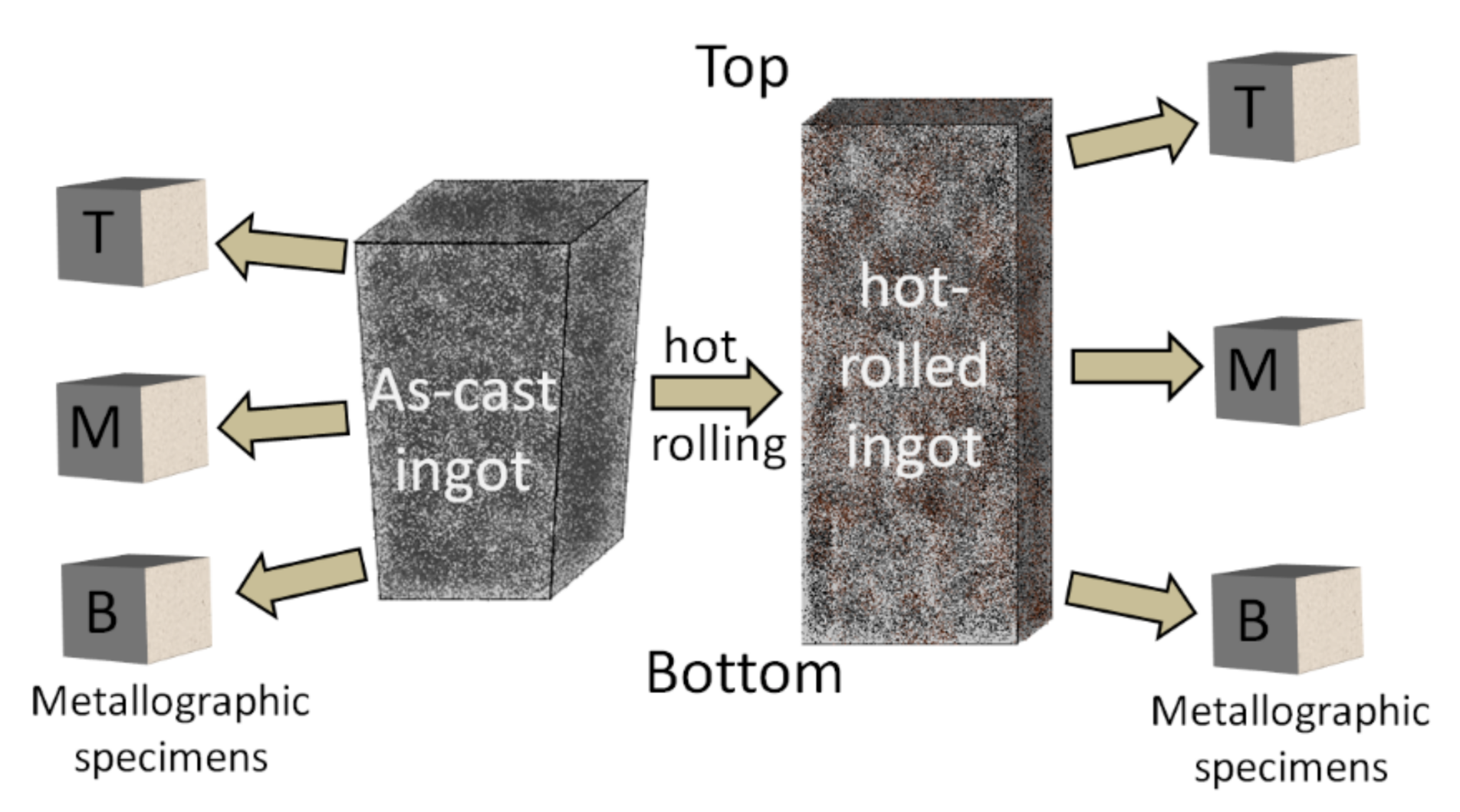
Samples for the microstructure analysis (10 mm cube) and determination of the nano-particle distribution homogeneity were taken from different sections of the as-cast or cast and hot-rolled ingot (Figure 2). Multiple samples were taken from the top, middle, and bottom part of the produced ingots, with the micrographs shown in this paper always taken from the middle section samples.
Specimens were metallographically prepared using a standard metallographic procedure for stainless steel (grinding with SiC paper, followed by polishing with a 1-µm diamond suspension). Aqua regia (10 mL HNO3 + 30 mL HCl + 20 mL glycerol) in a molar ratio of 1:3:2 was used to reveal the microstructure, which was examined by Microphot FXA (Nikon, Tokyo, Japan), a Nikon light microscope with a built in 3CCD-videocamera Hitachi HV-C20A, and computer software analysis. Scanning electron microscopy (SEM; JSM-6500F, Jeol, Tokyo, Japan) with back-scattered (BSE) detector and energy dispersive X-ray spectroscopy (EDS) were used for microstructure analysis, investigation of the inclusions, particle distribution and detailed chemical composition. In order to determine the size distribution of nano-particles smaller than 500 nm, secondary electron images (SEI) taken at 15 kV accelerating voltage at 20,000× magnification and covering an area of about 30 µm2 (6.0 µm × 4.8 µm) were analyzed using FIJI (ImageJ) software (ImageJ, ver. 1.52p, Bethesda, MD, USA). For each case, at least 10 randomly selected areas were analyzed. Analysis of the particles’ distribution and size for particles larger than 500 nm, and multiple surface areas of 1 mm × 1 mm were analyzed using SEM automatic feature analysis (Oxford Instruments INCA Energy, Oxford, UK) Atomic-resolution scanning-transmission electron microscope (A JEOL, ARM 200 CF, AR STEM, Jeol, Tokyo, Japan) was used for nano-scale microstructure investigation. Samples for the Transmission Electron Microscopy (TEM) were prepared by slicing the samples into thin foils (0.5–1.0 mm) with a length of up to 3 mm. After polishing the foils down to a thickness of 100 ± 10 µm, final milling was carried out with an Ion Slicer (IonSlicer, EM-09100IS, Jeol, Tokyo, Japan).

3. Results and Discussion

3.1. Thermodynamic Calculations

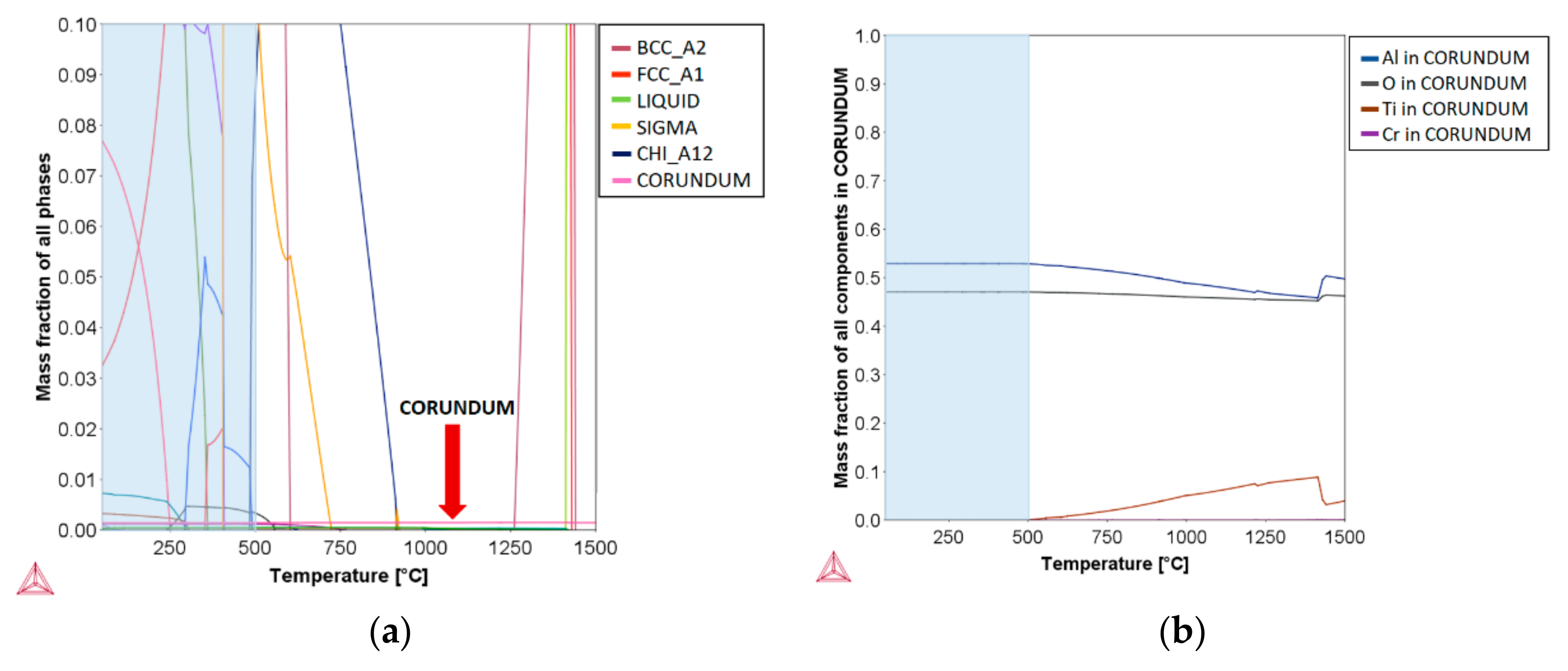
In thermodynamic calculations, stable as well as unstable phases were considered, including phases that can occur only at higher amounts of silicon or phosphorous, i.e., silicides (G-phase) and phosphides (M3P). However, most of these phases are present in very small quantities due to a very low impurities level. The analyzed temperature range was from 50 to 1500 °C, thus covering the whole solidification and cooling region from the liquid phase of the AISI 316L steel. However, the phases indicated to occur below 500 °C are unlikely to be present in reality (highlighted area in Figure 3). Cooling rates to room temperature are too fast to enable formation of the equilibrium phases. On the other hand, the phases that can be expected and are important for the current experimental work include: FCC_A1 (austenite), BCC_A2 (ferrite), liquid phase, and sigma phase, while corundum represents the stable phase of Al2O3. The addition of nano-particles in the melt was simulated by the addition of aluminum and oxygen in the mass concentrations corresponding to the selected concentration of added nano-particles (i.e., 0.5 wt % of Al2O3 nano-particles corresponds to 0.265 wt % Al and 0.235 wt % O).
The thermodynamic calculation of phase stability for AISI 316L steel with the addition of 0.5 wt % Al2O3 nano-particles is shown in Figure 3. The results show that the Al2O3 phase remains undissolved also in the liquid region of the AISI 316L austenitic stainless steel matrix. The melting temperature of oxide particles is much higher (2072 °C for Al2O3) compared to the steel matrix (1400 °C) [2], and as shown in Figure 3b, the oxygen content in the corundum phase stays practically unchanged up to the matrix melting temperature of ≈1400 °C. On the other hand, the aluminum content is constant up to approximately 500 °C, followed by a slight drop, which is balanced by the increase in titanium concentration. This trend is present up to about 1400 °C, when the aluminum content again increases to the previous value and the titanium concentration drops accordingly. As indicated by the thermodynamic calculations, the Al2O3 phase, although declared as a high-temperature stability phase, may start reacting with some of the other elements, i.e., titanium. However, this is not changing the phase itself significantly.

3.2. Microstructure and Particle Distribution

In practice, a certain degree of thermomechanical processing is required to achieve a suitable final microstructure of stainless steel, which might require even further heat treatment. However, the aim of the current research was not to evaluate the effect of nano-particles on the final properties of AISI 316L steel, but on the possibility to successfully incorporate nano-particles into the steel matrix. Therefore, the investigation was performed on as-cast as well as on cast and hot-rolled ingots without a final annealing treatment. The as-cast microstructure analysis was performed to determine the effect of the concentration, size, and method of nano-particle addition on their distribution. On the other hand, hot-rolled samples were used to determine the stability of the nano-particles and their distribution after the hot-rolling process.

3.2.1. Reference Material

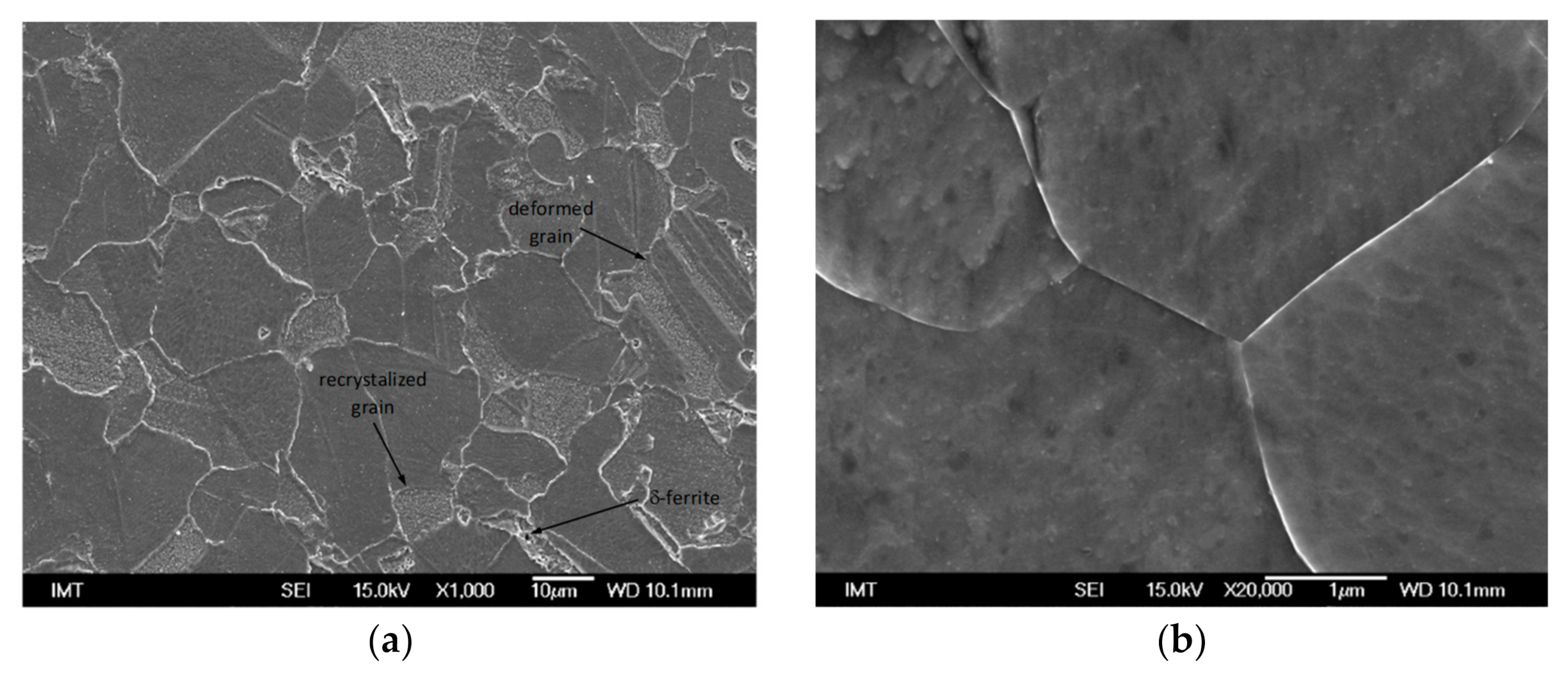
Previous microstructure studies of Kračun et al. [12] show that the matrix of as-cast reference AISI 316L austenitic stainless steel consists of a distinctive two-phase microstructure of austenite and δ-ferrite, which has solidified from the interdendritic melt. After hot rolling, a partially recrystallized microstructure with recrystallized grains was formed, as shown in Figure 4. The recrystallized grains are more or less free from defects, whereas the deformed regions show a large concentration of defects, such as dislocations and cell boundaries (not shown).

3.2.2. Submerging Method

In the case of the submerging method, with the Al2O3 nano-particles being encapsulated in the steel tube and the tube submerged into the base melt, no nano-particles could be found in the as-cast microstructure. The problem lies in the large density difference between the added Al2O3 nano-particles and the iron. The density of the Al2O3 nano-particles is 3.95 g/cm3 as compared to 7.85 g/cm3 of the iron. Due to the high surface tension and large density difference, nano-particles are easily agglomerated and transferred into the slag on the surface of the melt, even when using larger particles and high concentrations.

3.2.3. Pouring over Method

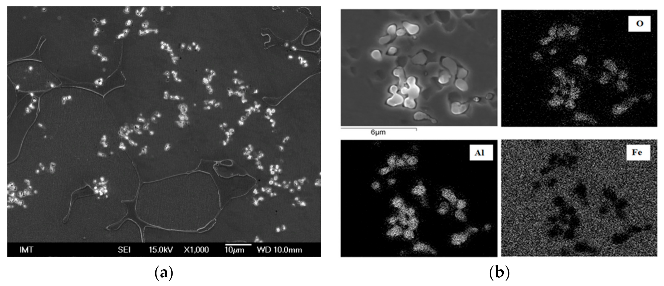
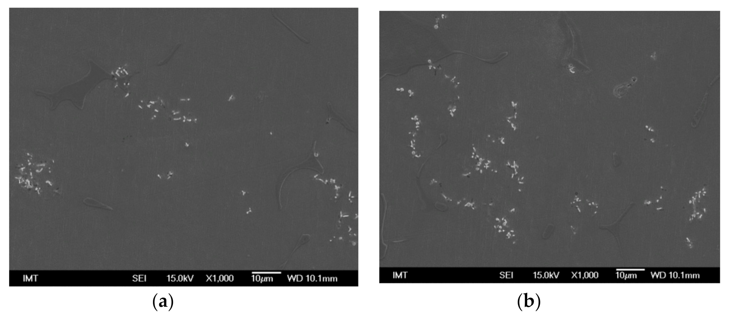
Experimental results from the pouring over method (P samples) indicate that the Al2O3 nano-particles can be successfully incorporated into the stainless steel matrix (Figure 5). From the SEM/EDS elemental mapping analysis shown in Figure 5b, it was confirmed that the bright, small, spot-like features represent the incorporated Al2O3 nano-particles, which are coherent bonded in the steel matrix (Figure 6). However, as shown in Figure 7, Figure 8 and Figure 9, the distribution of Al2O3 particles is non-homogeneous and concentrated in certain areas, forming reinforcement-particle clusters. Increasing the particle size and concentration leads to more pronounced agglomeration and clustering. On the other hand, when performing particle volumetric distribution analysis across the whole ingot (samples taken from different ingot positions, Figure 2), an even distribution of particles was observed for particle concentrations of 0.5 and 1.0 wt %, with very small deviations in the distribution over the ingot height of about 0.01 particles/μm2. Similar results were obtained regardless of whether the 50-nm or 500-nm sized particles were used. Nevertheless, when the mass fraction of added nano-particles was increased to 2.5 wt %, the particle volumetric distribution became non-uniform, with the nano-particles concentration decreasing toward the bottom of the as-cast ingot. Furthermore, at large concentrations, also the size of the particles starts to play a role, with the larger particles being more effectively incorporated into the steel matrix.

3.2.4. Insertion of Sealed Tube into the Melt Flow

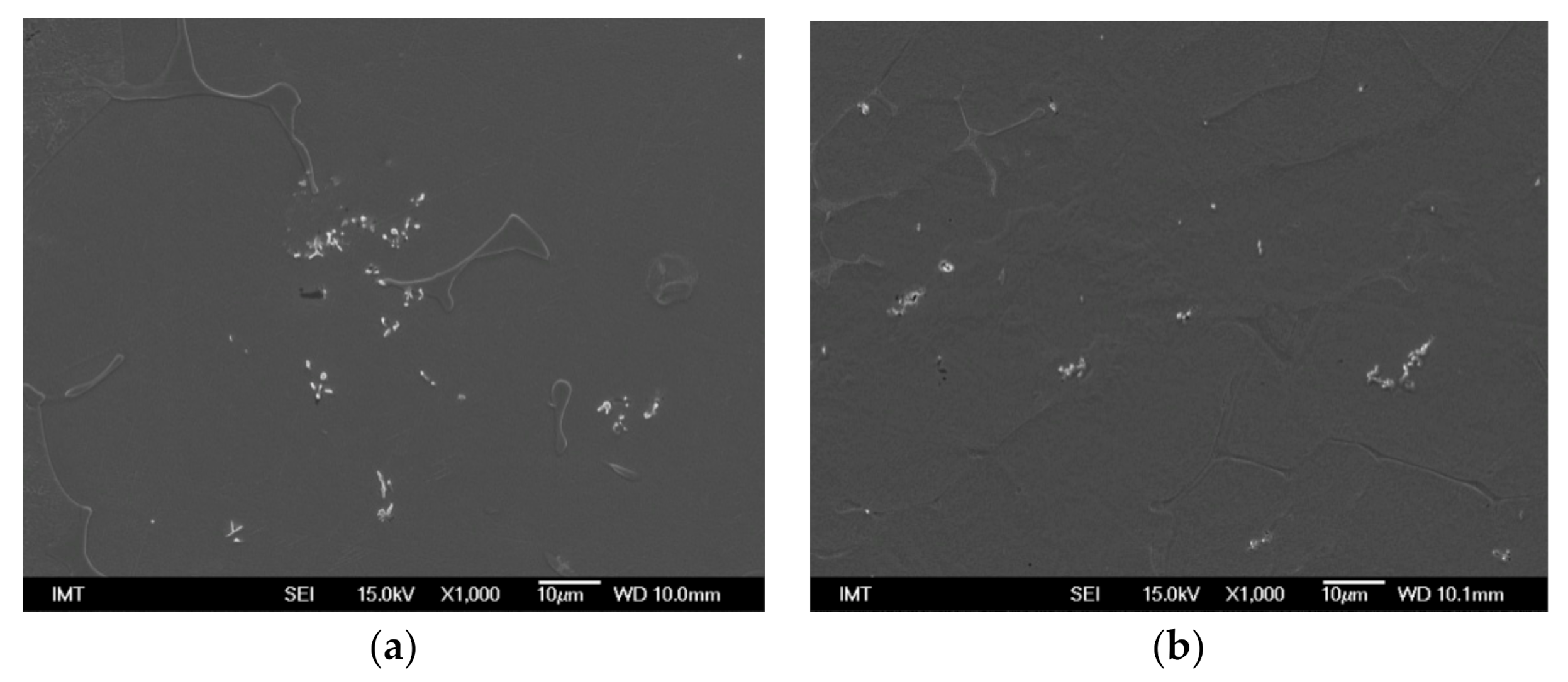
The third set of experiments comprised four batches (F1–F4) where Al2O3 nano-particles were encapsulated into the Al tube, and the tube was held in the path of the melt flow during casting. Two nano-particle sizes (500 nm and 50 nm) in the concentration of 0.5 wt % were used, once in a non-modified condition without any supplements (F1 and F3) and secondly mixed with a CaSi de-oxidant agent in a 1:1 mass ratio (F2 and F4). As shown in Figure 9, by using the in-melt flow insertion method and mixing nano-particles with CaSi, which may act as a dispersion agent, reduced nano-particle clustering and a more homogeneous distribution are obtained. The particle distribution analysis also showed a reduced particle size effect if nano-particles are mixed with a dispersion agent [12]. When the CaSi comes into contact with molten steel, a turbulent reaction scatters the particles through the whole volume of the melt, thus providing more effective particle dispersion, reduced particle clustering, and a more homogeneous distribution in the metal matrix.
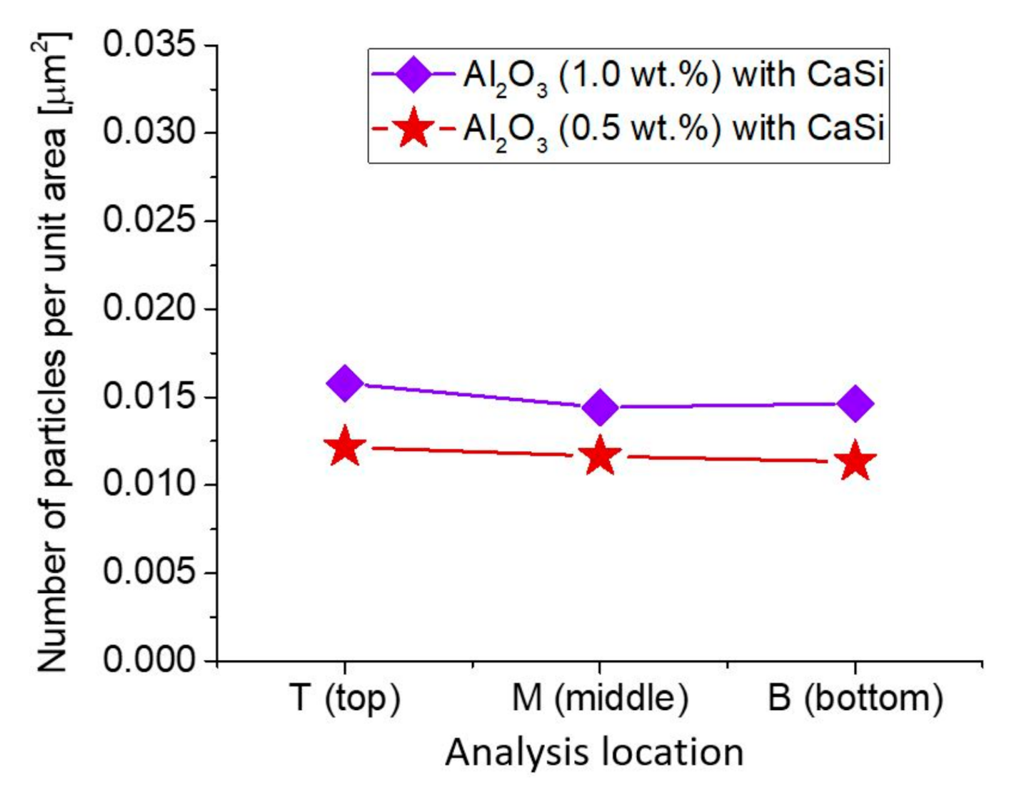
Due to the improved distribution homogeneity, all further experiments were conducted using an in-melt flow insertion method and nano-particles/CaSi mixture in a 1:1 mass ratio. Furthermore, to eliminate any potential influence of the aluminum tube on the formation of non-metallic inclusions, i.e., aluminates, it was replaced by a ferritic steel tube of the same dimensions. Thus, the fourth set of experiments (F5 and F6) was conducted, analyzing the effect of 50 nm sized nano-particles concentration (0.5 wt % and 1.0 wt %) when mixed with a CaSi dispersion agent and added by being encapsulated in the steel tube and inserted into the melt flow during casting. Using a steel tube and CaSi as a dispersion agent resulted in reduced particle clustering, reduced non-metallic inclusions formation, and a more homogeneous distribution of the reinforcement nano-particles in the steel matrix. A concentration-dependent analysis, as presented in Figure 10, shows that with increased nano-particles concentration, the mass fraction of incorporated Al2O3 nano-particles in the steel matrix increases, but it become less homogeneously distributed through the whole volume of the as-cast ingot. In the case of 0.5 wt % concentration, the incorporated nano-particles mass fraction is around 0.012/µm2 and increases to 0.015/µm2 for 1.0 wt % concentration, but it shows a more pronounced drop toward the bottom of the as-cast ingot.
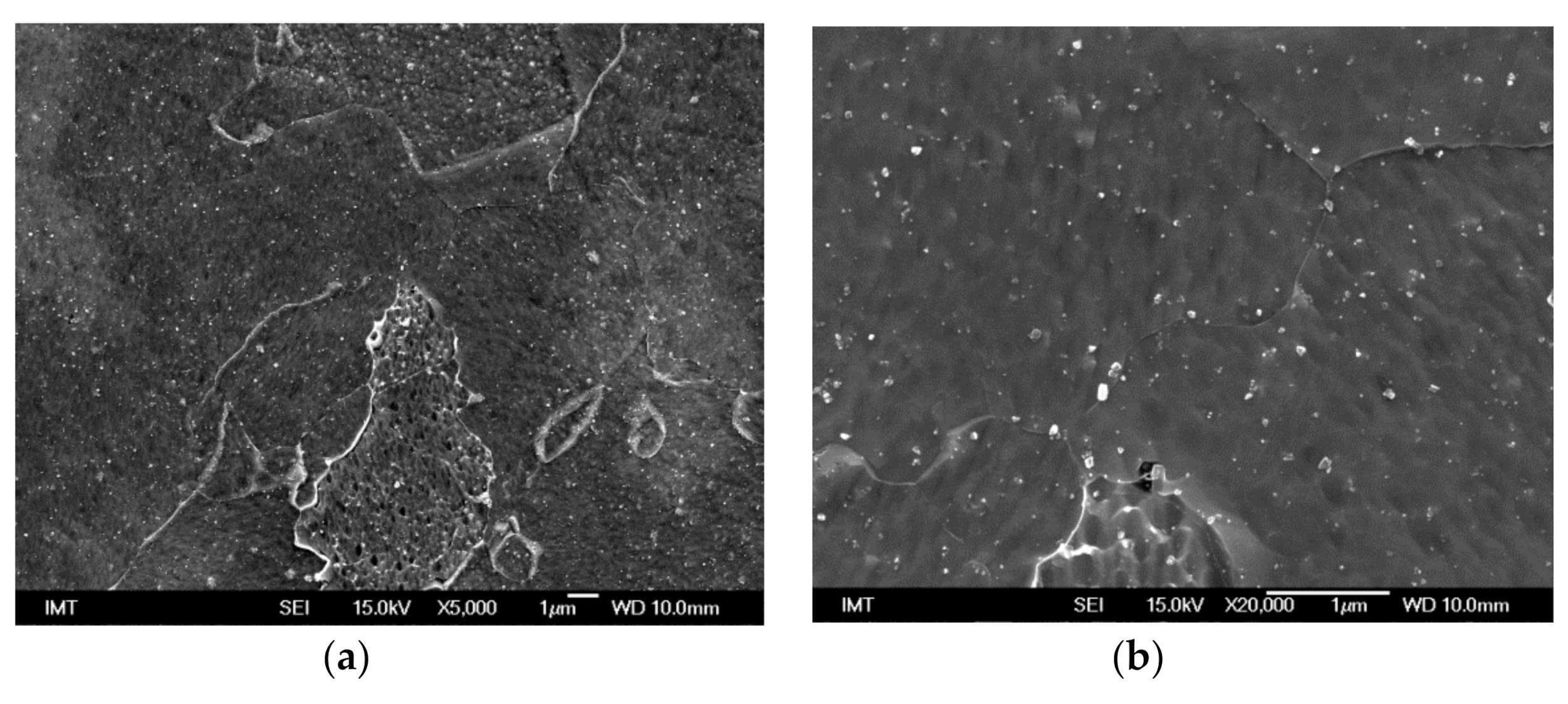
To confirm and further investigate the effectiveness of Al2O3 nano-particles incorporation into the stainless steel matrix, additional 8 kg batches involving 50 nm sized nano-particles added in 0.5 wt % concentration through the in-melt flow insertion method were produced, and as-cast ingots were subjected to an additional hot-rolling process. As shown in Figure 11, Figure 12, Figure 13, Figure 14 and Figure 15, also for larger batches and after thermo-mechanical treatment, the effective incorporation of Al2O3 nano-particles in the stainless steel matrix without any evident intermetallic reactions can be obtained. However, nano-particles powder preparation is important. In the case of “pure” Al2O3 nano-particles, which are not mixed with the dispersion agent (sample A1), the particles are non-uniformly distributed in the matrix, with particle clustering taking place (Figure 11). Increasing the Al2O3 nano-particles’ surface energy by activation in oxygen plasma (A3) [13] did not had any evident effect, neither on the way the nano-particles are incorporated into the steel matrix, nor on the distribution homogeneity and clustering. However, when Al2O3 nano-particles are mixed with the CaSi de-oxidant agent (sample A2) and/or activated (sample A4), they are more effectively incorporated and more uniformly distributed in the matrix with reduced clustering, as shown in Figure 12.
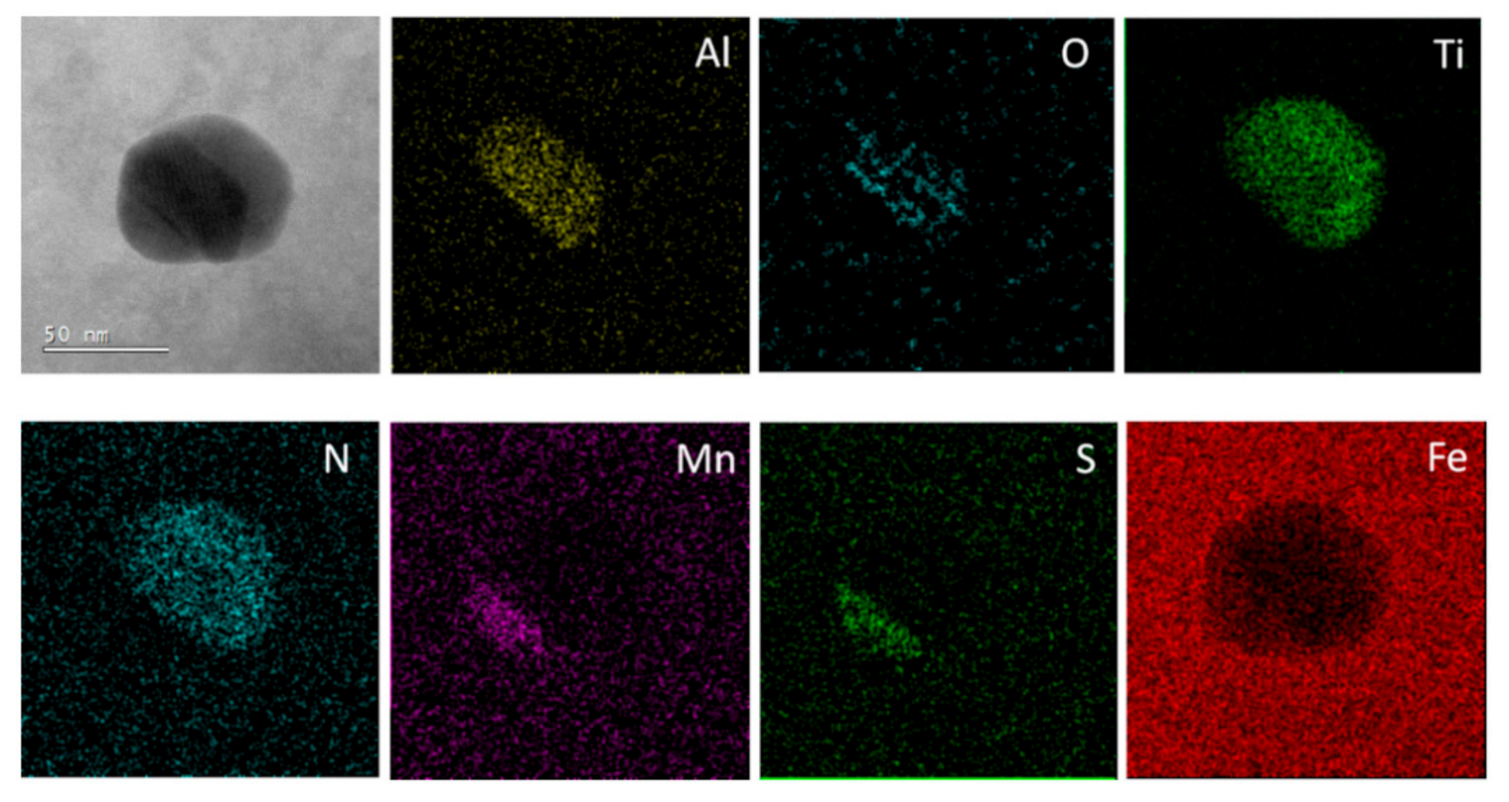
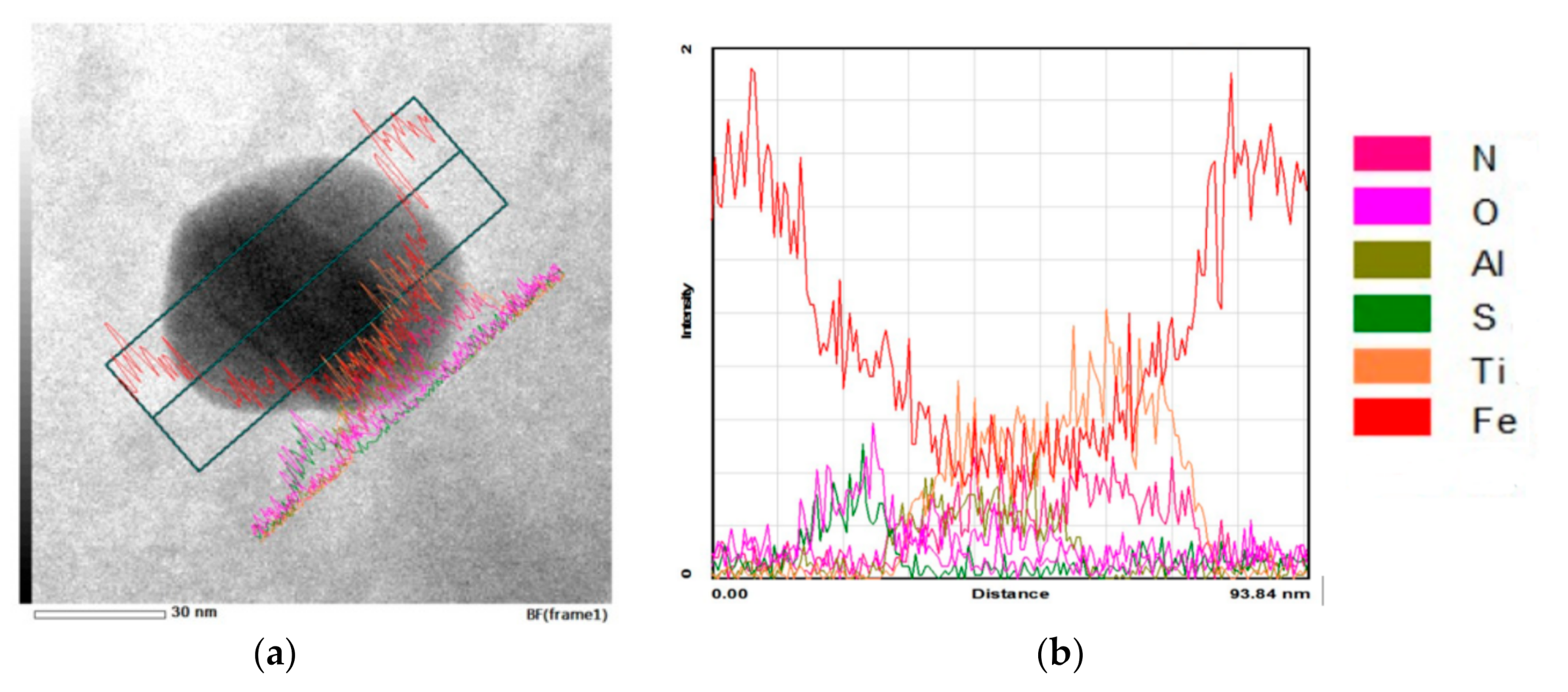
The successful incorporation of Al2O3 nano-particles in the stainless steel matrix without any evident intermetallic reactions and their coherent bonding was confirmed by Transmission Electron Microscopy (TEM) analysis (Figure 13, Figure 14 and Figure 15). TEM/EDS elemental mapping was used to confirm the presence of nano-particles incorporated into the steel matrix, which are smaller than 500 nm (Figure 14), while STEM line-profile analysis showed no intermetallic phases at the nano-particle/matrix interface (Figure 15). TEM analysis indicate that the thermodynamically stable Al2O3 nano-particles stayed largely undissolved in the steel matrix. However, also some other elements could be detected around the Al2O3 nano-particles, such as titanium, nitrogen, manganese, and sulfur. Titanium in base steel could react with the Al2O3 nano-particles, resulting in the formation of complex oxides. Another explanation could be the nucleation and formation of TiN and MnS on the added nano-particles. The whole system is in the 50-nm size range. The ThermoCalc calculations also predicted the presence of titanium in the corundum phase (Figure 3b).
The nano-particle homogeneity was further investigated by particle size distribution analysis performed by using the automated Oxford INCA Feature (particle size above 500 nm), which classifies particles by morphology, chemistry, and position, and FIJI (ImageJ) software (particles smaller than 500 nm) based on manual image analysis. The size distribution of the nano-particles is presented with the equivalent circular dimeter (ECD). In the case of adding 50 nm sized Al2O3 nano-particles in 0.5 wt % concentration without using any dispersion agent (sample A1), about 15% of incorporated particles were smaller than 600 nm, and out of those, 15% were smaller than 200 nm, with the size distribution showing an exponential increase in density as the particles become smaller (Figure 16a). In general, particle size distribution follows the distribution shown by the starting powder analysis, with the particles ranging from 50 nm up to over 1 µm. By mixing Al2O3 nano-particles with a dispersion agent (sample A2 and A4), the density of particles smaller than 600 nm increased to over 15%, and particles smaller than 200 nm increased to about 25% (Figure 16b). This confirms that the dispersion agent (i.e., CaSi) reduces the particle clustering and helps maintain a smaller particle size.

4. Conclusions

The results of this investigation indicate that the ex-situ Al2O3 nano-particles incorporation and reinforcement of steel is feasible even when using simple liquid–metal casting routes. The most promising results and homogenous distribution of Al2O3 nano-particles in the steel matrix is obtained when the 50 nm sized nano-particles in low concentration (below 1.0 wt %) are mixed with the CaSi, sealed into a thin steel tube, and inserted into the melt flow during the ingot casting process. Furthermore, no negative effect of nano-particle addition on microstructure or grain size of AISI 316L austenitic stainless steel could be identified.
By using CaSi as a dispersion agent, reduced particle clustering and a more homogeneous distribution of the reinforcing nano-particles in the steel matrix and throughout the whole volume of the cast ingot is obtained. CaSi, when in contact with molten steel, causes a turbulent reaction and scatters the nano-particles throughout the whole volume of the melt. The dispersion agent also reduces the influence of the particle size on the particle distribution in the steel matrix. On the other hand, the plasma surface activation of Al2O3 nano-particles does not show any signs of improvement in terms of the uniformity of nano-particle distribution or the prevention of particles agglomeration and clustering.
Al2O3 nano-particles were selected due to the high thermodynamic stability as indicated by the thermodynamic calculations. TEM analysis revealed that Al2O3 nano-particles, which remained largely undissolved, were successfully incorporated in the stainless steel matrix by coherent bonding and without any evident intermetallic reactions. However, some of the other elements were also detected around the Al2O3 nano-particles, including TiN and MnS, indicating that added Al2O3 nano-particles may act as the nucleation sites for complex non-metallic inclusions formation.

Author Contributions

Conceptualization, writing—review and editing, A.K. and B.P.; methodology, A.K., B.P. and F.T.; software, funding acquisition and project administration, B.P.; validation and supervision, B.P. and F.T.; formal analysis, resources and data curation, A.K. and F.K.; investigation, writing—original draft preparation and visualization, A.K. All authors have read and agreed to the published version of the manuscript.

Funding

This work was done in the frame of the research programs P2-0050 which is financed by the Slovenian Research Agency.

Acknowledgments

The authors would also like to acknowledge help from Francisco Ruiz Zepeda from the Institute of Metals and Technology for TEM investigations. M. Torkar, B. Arh, F. Vode and Z. Majer from the Institute of Metals and Technology for the melting and casting.

Conflicts of Interest

The authors declare no conflict of interest. The funders had no role in the design of the study; in the collection, analyses, or interpretation of data; in the writing of the manuscript, or in the decision to publish the results.

References

  1. Kaczmar, J.W.; Pietrzak, K.; Wlosinski, W. The production and application of metal matrix composite materials. J. Mater. Process. Technol. 2000, 106, 58–67. [Google Scholar]
  2. Casati, R.; Vedani, M. Metal Matrix Composites Reinforced by Nano-Particles—A Review. Metals 2014, 4, 65–83. [Google Scholar] [CrossRef]
  3. Bakshi, S.R.; Lahiri, D.; Agarwal, A. Carbon nanotube reinforced metal matrix composites—A review. Int. Mater. Rev. 2010, 55, 41–64. [Google Scholar] [CrossRef]
  4. Hussainova, I. Effect of microstructure on the erosive wear of titanium carbide-based cermets. Wear 2003, 255, 121–128. [Google Scholar] [CrossRef]
  5. Sethi, G. Pressing to Full Density: Fundamental Limitations and Capabilities of High Density Powder Metallurgy. Ph.D. Thesis, Pennsylvania State University, University Park, PA, USA, December 2004. [Google Scholar]
  6. Swift, K.G.; Booker, J.D. Manufacturing Process Selection Handbook; Butterworth-Heinemann: Oxford, UK, 2013. [Google Scholar]
  7. Chawla, K.K. Metal matrix composites. In Composite Materials; Springer: Birmingham, AL, USA, 2012; pp. 197–248. [Google Scholar]
  8. Sarma, M.; Grants, I.; Kaldre, I.; Bojarevics, A.; Gerbeth, G. Casting technology for ODS steels - Dispersion of nanoparticles in liquid metals. IOP Conf. Ser. Mater. Sci. Eng. 2017, 228, 012020. [Google Scholar] [CrossRef] [Green Version]
  9. Chen, S.; Seda, P.; Krugla, M.; Rijkenberg, A. High-modulus steels reinforced with ceramic particles through ingot casting process. Mater. Sci. Technol. 2016, 32, 992–1003. [Google Scholar] [CrossRef]
  10. Kračun, A.; Jenko, D.; Godec, M.; Savilov, S.V.; Prieto, G.; Tuckart, W.; Podgornik, B. Nanoparticles Reinforcement for the Improved Strength and High-Temperature Wear Resistance of Mn-Cr Steel. Metall. Mater. Trans. A Phys. Metall. Mater. Sci. 2018, 49, 5683–5694. [Google Scholar] [CrossRef]
  11. Thermo-Calc Software: Thermo-Calc. Available online: http://www.thermocalc.com/products-services/software/thermo-calc/ (accessed on 13 May 2020).
  12. Kračun, A.; Torkar, M.; Burja, J.; Podgornik, B. Microscopic characterization and particle distribution in a cast steel matrix composite. Mater. Tehnol. 2016, 50, 451–454. [Google Scholar] [CrossRef]
  13. Bazaka, K.; Baranov, O.; Cvelbar, U.; Podgornik, B.; Wang, Y.; Huang, S.; Xu, L.; Lim, J.W.M.; Levchenko, I.; Xu, S. Oxygen plasmas: A sharp chisel and handy trowel for nanofabrication. Nanoscale 2018, 10, 17494–17511. [Google Scholar] [PubMed]
Figure 1. The methods of particle additions: (a) submerging, (b) pouring over method, (c) insertion of sealed tube into the melt flow during casting.
Metals 10 01287 g001
Figure 2. Schematic diagram of the subtraction of the metallographic samples.
Metals 10 01287 g002
Figure 3. ThermoCalc calculations of phase stability for AISI 316L stainless-steel matrix with the addition of 0.5 wt % Al2O3 nano-particles: (a) mass fraction of all phases present from 0 to 0.1% and (b) elemental composition of CORUNDUM phase.
Metals 10 01287 g003
Figure 4. Cast and hot-rolled microstructure of reference AISI 316L austenitic stainless steel sample (R1) without the addition of nano-particles at (a) 5000× magnification and (b) 20,000× magnification.
Metals 10 01287 g004
Figure 5. As-cast microstructure of AISI 316L austenitic stainless steel with the addition of 0.5 wt % 500 nm sized Al2O3 nano-particles (sample P1-M taken from the middle part of the as-cast ingot): (a) scanning electron microscope SEM micrograph and (b) SEM/EDS elemental mapping.
Metals 10 01287 g005
Figure 6. Scaning transimison electron microscope (STEM) line profile of the incorporated Al2O3 nano-particle (500 nm, 0.5 wt %—sample P1) in the as-cast microstructure of AISI 316L austenitic stainless steel with (a) indicated area of analysis and (b) STEM line profile.
Metals 10 01287 g006
Figure 7. As-cast microstructure of AISI 316L austenitic stainless steel with the addition of 500 nm sized Al2O3 nano-particles: (a) 1.0 wt % (sample P2) and (b) 2.5 wt % (sample P3); samples taken from the middle part of the as-cast ingot.
Metals 10 01287 g007
Figure 8. As-cast microstructure of AISI 316L austenitic stainless steel with the addition of 50 nm sized Al2O3 nano-particles: (a) 0.5 wt % (sample P4) and (b) 2.5 wt % (sample P6); samples taken from the middle part of the as-cast ingot.
Metals 10 01287 g008
Figure 9. As-cast microstructure of AISI 316L austenitic stainless steel with the 50-nm sized Al2O3 nano-particles (0.5 wt %) added through the in-melt flow insertion method: (a) non-modified Al2O3 nano-particles powder (sample F3) and (b) Al2O3 nano-particles mixed with CaSi in a 1:1 mass ratio (sample F4); samples taken from the middle part of the as-cast ingot.
Metals 10 01287 g009
Figure 10. Influence of nano-particles concentration on the particle distribution in the as-cast ingot.
Metals 10 01287 g010
Figure 11. Cast and hot-rolled microstructure of AISI 316L austenitic stainless steel with the addition of 0.5 wt % Al2O3 nano-particles (sample A1); (a) 5000× magnification and (b) 20,000× magnification.
Metals 10 01287 g011
Figure 12. Cast and hot-rolled microstructure of AISI 316L austenitic stainless steel with the addition of 0.5 wt % Al2O3 nano-particles activated in oxygen plasma and mixed with CaSi in 1:1 mass ratio (sample A4); (a) 5000× magnification and (b) 20,000× magnification.
Metals 10 01287 g012
Figure 13. High-angle annular dark-field imaging (HAADF)/STEM image of AISI 316L austenitic stainless steel with the incorporated nano-particles (indicated by arrows).
Metals 10 01287 g013
Figure 14. STEM/EDS elemental mapping of Al2O3 nano-particles in the microstructure of AISI 316L austenitic stainless steel; sample A2.
Metals 10 01287 g014
Figure 15. STEM line-profile analyses of Al2O3 nano-particle in the microstructure of AISI 316L austenitic stainless steel; sample A2: (a) indicated area of analysis and (b) STEM line profile.
Metals 10 01287 g015
Figure 16. Al2O3 particle size distribution within the steel matrix for (a) sample A1 (0.5 wt % Al2O3 nano-particles) and (b) sample A2 (0.5 wt % Al2O3 nano-particles mixed with CaSi in 1:1 mass ratio).
Metals 10 01287 g016
Table 1. Chemical composition of the base AISI 316L austenitic stainless steel in wt %.
CSiMnPCuSCrNiMoTiNCoV
0.020.481.880.030.320.0316.6010.702.010.160.020.170.04
Table 2. Al2O3 nano-particles concentration, size, and method of introduction.
SampleParticle Size [nm]Particle Concentration [%]MethodDispersant/Particle Activation
As-cast experiments
R1--Reference material-
S15001.0Submerging 1-
P15000.5Pouring over method 2-
P21.0-
P32.5-
P4500.5-
P51.0-
P62.5-
F15000.5Insertion into the melt flow during casting 3-
F2CaSi (1:1)
F350-
F4CaSi (1:1)
F5500.5Insertion into the melt flow during casting 4CaSi (1:1)
F61.0CaSi (1:1)
Cast and hot rolled experiments
R2--Reference material-
A1500.5Insertion into the melt flow during casting 4-
A2CaSi (1:1)
A3activated
A4CaSi (1:1)/activated
1 Submerging of the steel tube with encapsulated nano-particles directly into the melt prior to casting. 2 Nano-particles were placed on the bottom of the cuboid-shaped steel mold wrapped in an aluminum foil and then poured over with molten steel matrix (2 kg). 3 Nano-particles were encapsulated in an aluminum tube and held in the path of the melt flow when casting into the mold started (2 kg). 4 Nano-particles were encapsulated into the steel tube and held in the path of the melt flow when casting into the mold started.