1. Introduction
Since the pre–Hispanic era to date, Mexico has been a mining country, and this activity has pointed more on precious metals ores. Particularly in the mining district of “Pachuca-Real del Monte” in the State of Hidalgo, the mineral processing has included several technologies ranging from the benefit of “Patio”, froth flotation, and cyaniding, generating over 460 years of tailings that is deposited in four mining dams. “Dos Carlos” is one of the oldest [
1]. The principal species found in this kind of residues is Si with content from 56% to 70%, and the presence of Ag and Au, which has given added value to these waste [
1,
2].
Due to the above pointed, some works have devoted to recovering the metallic values involved in these waste [
1,
3,
4], leading so a second residue with important amounts of SiO
2 and feldspars, which could also be of commercial interest.
As was pointed, the “Dos Carlos” dam is one of the oldest in the Pachuca-Real del Monte Mining District, established since 1912. Consequently, this dam has an approximate amount of waste (coming from the processes of grinding, flotation and cyanidation) of more than 14.3 million tons [
1]. These residues have a chemical composition corresponding to 70.43% SiO
2, 7.32% Al
2O
3, 2.32% Na
2O, 0.08% K
2O, 0.69% CaO, 0.54% MgO, 0.73% MnO, 2.80% Fe
2O
3, 2.41% FeO, 0.53% TiO
2, 0.12% P
2O
5, 55 ppm of Ag, and 0.58 ppm of Au [
5,
6]. Similarly, the described residues show a coarse granulometry of the order of 60% accumulated up to the 270 mesh (53 μm) [
5].
These residues constitute an important source of materials that can be effectively reused, considering that the contents of silica and feldspars can be recovered; the silver and gold and finally the residual oxides. Therefore, the recovery and the obvious market for precious metals [
7] results in direct profits, while the demand for silica and feldspars includes the ceramics, chemistry, glass, abrasives, silicate acid refractories, additives [
8], and finally the oxides for the cement and glass industry.
Regarding the flotation of material from natural siliceous sand deposits, there are different methods and uses of reagents, depending on the impurities contained in the siliceous sand. For feldspathic sands with quartz, fatty acids are mainly used as collectors in a neutral or slightly basic medium during the primary phase of elimination of iron and titanium oxides. In the secondary stage, it is necessary the elimination of micas and feldspars, which is achieved from primary amine collectors in acid medium, by the addition of sulfuric acid. In addition, in the removal of feldspars, ammonium bifluorofuroide is used as a depressant agent, achieving that the silica law reaches 98% of purity, with minimum additions of the order of 0.97% Al
2O
3 and 0.05% Fe
2O
3 [
9].
Moreover, the separation during the second phase is achieved by acidic pH of the order of 2 to 2.5, using H
2SO
4 or failing with HF, in a concentration of 2000–2500 ppm. The latter is also a depressant of the feldspathic portion, providing that the silica particle can be cleaned superficially from metal oxides; this modified process generated a silica content of 98.36% [
10].
Besides, it is also possible to use cationic reagents based on complex sulfates, for the flotation of the silica from sands containing quartz and feldspar; by using silica activating agents such as Ca
2+, Ba
2+ and Sr
2+, thus achieving an adequate flotation of the silica without the use of HF [
11].
In a nutshell, the glass and chemical industries require a high standard of silica quality that means composition over 99.8%, with impurities less than 0.02% of hematite and alumina, as well as values lower than 0.1% of lime and magnesia [
12]. Nevertheless, comparing with the previous investigations, the silica recoveries are still far from the amount expected to place it in the industries mentioned above.
Since flotation is a process widely used for mineral concentration, the study of size and quantity of bubbles, the particle sizes and hydrophobic conditions, and many other factors are of great importance [
13]. According to this, mineral extraction from tailing is a technological challenge in mining and metallurgical operations. It needs an in-depth study of technical and economic feasibility [
14], being the flotation an adequate technique for the concentration and recovery of minerals from ores and waste. The flotation in column also represents an appropriate option for the recovery and or concentration of minerals, where the model studied is related to a stable state behavior, taking in account variables such as dynamic mass balance, type of pulp, markers, bubble distribution and flux, bubble size, cations effect, and bubble coalescence, among others [
15,
16,
17].
In this context, the principal aim of this work is to recover silica by column flotation, using the tailings form the “Dos Carlos” dam. This proposal offers significant advantages since it reuses a material considered waste. Thus it will be given a higher value, and unlike the processes used commercially, as described in previous paragraphs, it will be more advantageous and viable.
2. Materials and Methods
Firstly, the material used in this work was waste coming from the mining industry of the mining district of Pachuca-Real del Monte, which was sampled selectively at the “Dos Carlos” dam, using the channel technique. The sample so collected was homogenized by quartering and then characterized to disclose the mineral species involved and its chemical composition. The whole characterization was carried out by X-ray diffraction (XRD), using an Equinox 2000 diffractometer (INEL, Artenay, France) with CoKα 1 radiation (λ = 1.78901 Å), at 30 kV, 20 mA and a scanning speed of 22 θ/min. Phase identification was based on the COD Inorganics 2015 and Cements 2014 databases included in the Crystallography Open Database; Match! software used in this procedure (v.1.10, Crystal Impact, Bonn, Germany).
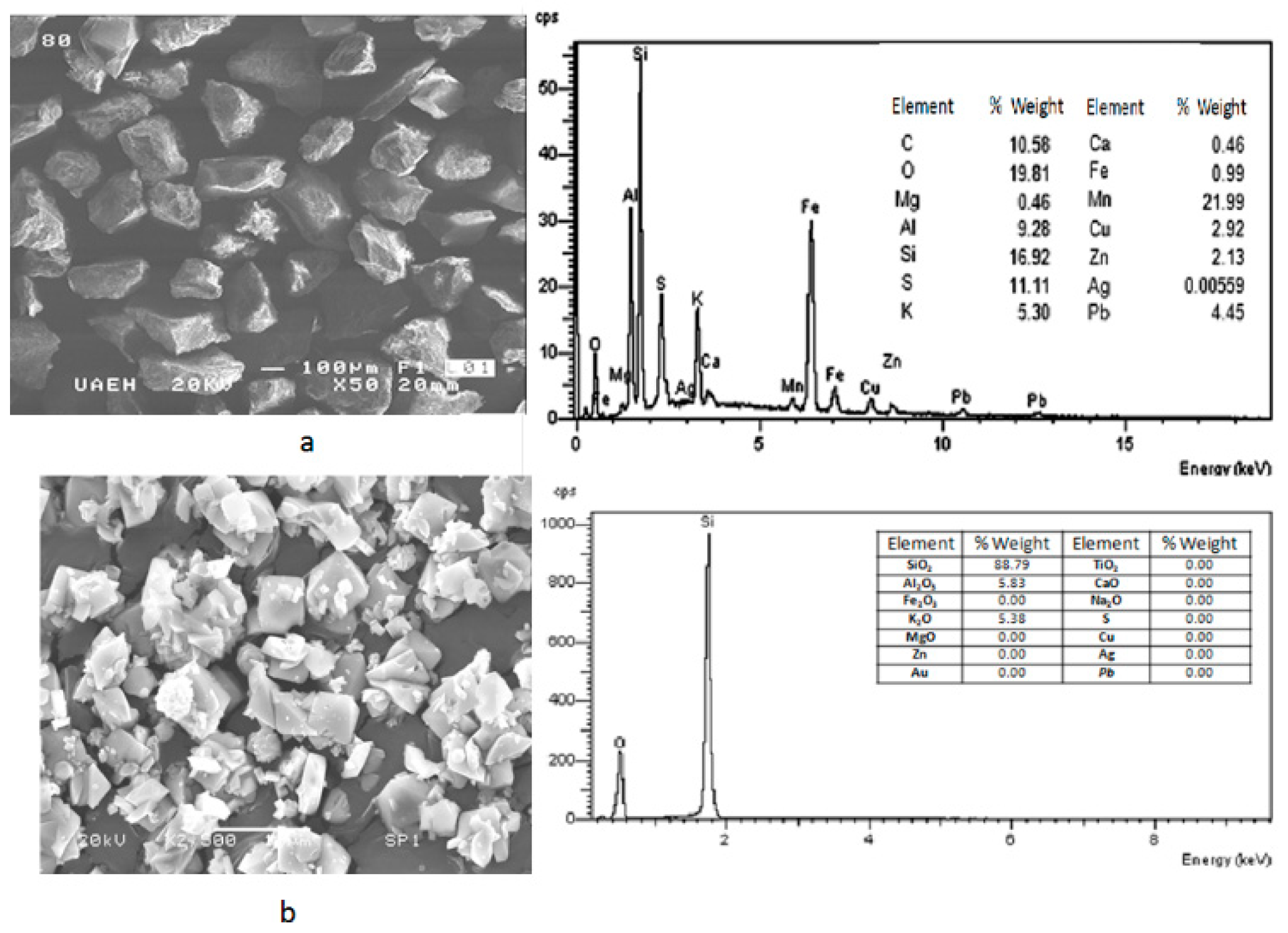
In addition, the shape and size of waste particles were determined by a scanning electron microscopy, in conjunction with energy dispersive spectrometry of X-Rays (SEM-EDS). In this case was used a JEOL scanning electron microscope, model JSM-IT300 (JEOL Ltd., Tokyo, Japan) which has an OXFORD X-ray detector (OXFORD Instruments, Oxfordshire, UK), employing an acceleration voltage of 30 kV.
Secondly, the chemical determination was executed by atomic absorption spectroscopy (AAS) using a spectrophotometer Perkin Elmer model 2380. In addition, X-ray fluorescence (XRF) chemical analysis was run by a SIEMENS spectrophotometer belonging to the ceramic company Morgan SA of CV, located in Pachuca, Mexico. Samples were mixed with lithium hexaborate in a 5:1 ratio and then fused in a furnace at 1473 K to obtain a button, which was irradiated with an Rh anticathode using the following crystals for their evaluation; LiF200, Ge111, and T1AP. Calibration was done using different oxides of known composition.
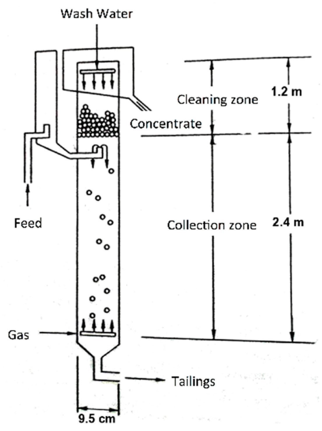
On the other hand, the recovery of the silica was carried out in a flotation column with two cleaning stages (
Figure 1), using a concentration of 3% solids, and 50 ppm of analytical grade dodecylamine of the brand Sigma-Aldrich (C
12H
25-NH
2). The frother reagent was methyl isobutylcarbonyl or MIBC in a concentration of 60 ppm (Alkemin), adjusting to a
Jg value of 0.3 cm/s, a
JLT of 0.45 and 0.68 cm/s, respectively, and without the addition of any depressant.
The respective values of εg (retained gas), Db (particle size), and Sb (surface bubble rate) were determined from the experiments; taking samples in each Jg value, in the feed streams, tails and concentrate.
Finally, the concentrates resulting from the batch tests were characterized by XRD. The samples were sieved to obtain sizes between 74 and 53 μm (Tyler® 200 and 270 series meshes, respectively). Once this range of sizes was obtained, 1 g of sample was weighed and compacted in an aluminum sample holder for further analysis by XRD, determining the mineral phases present.
3. Results
The results obtained by SEM-EDS are shown in
Figure 2, where can be seen the general morphology of samples (Saning Electron Microscopy–Secondary Electrons (SEM-SE)) and its punctual composition obtained by EDS (a) before flotation stage, and (b) after flotation process. It can be noted that after the flotation of material, the residue resting has been enriched with SiO
2.
In the case of the X-ray fluorescence, the obtained results are shown in
Table 1. It is appreciated that the dominant species contained were silica, alumina, hematite, and potassium oxide, having also minor species such as magnesium oxide, calcium oxide, lead, zinc copper, silver, and gold.
Figure 3 (1st stage line) displays the gas retained in the columnar flotation system, for the recovery in the batch system during the first stage of cleaning, with a flow of liquid in the stream of tails (
JLT) of 0.45 cm/s, and applying a gas flow (
Jg) of 0.3 cm/s. Additionally, the lowest concentration of gas retained appeared in the central area of the column (manometers 2 and 3), because in this zone, the bubble pack had a higher rate of ascent. On the other hand, in the upper part of the column, an increase of gas retained in the system was observed, with a value of 3.3%, decreasing the rising speed of the bubble package. The percentage of global retained gas was 2.3%.
Likewise, same
Figure 3 (2nd stage line) shows the determination of retained gas (
εg) in the columnar flotation system, for the recovery in batch system during the second cleaning stage, with a flow of liquid in the queuing stream (
JLT) of 0.45 cm/s, applying the gas flow (
Jg) of 0.3 cm/s. In the central zone of the column (manometers 2 and 3), the highest concentration of gas retained in the system was presented, where the bubble packing has a lower acceleration. Besides, the values of gas retained at the ends of the column were similar at the top, which were slightly higher. The global percentage of gas retained was set at 15.2%.
Similarly,
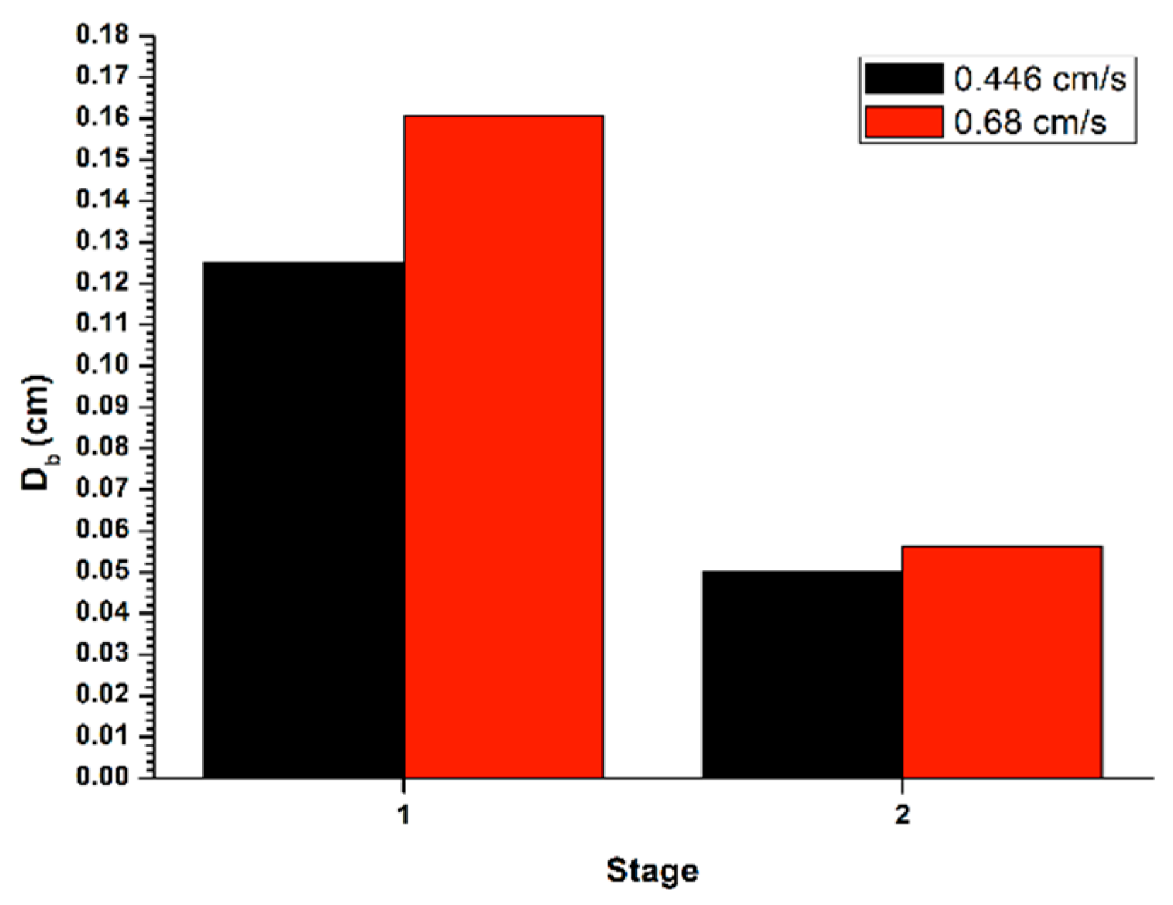
Figure 4 shows the bubble size (
Db) generated in the disperser, for the recovery in a batch system, with a flow of liquid in the tail stream (
JLT) of 0.45 cm/s, applying the gas flow (
Jg) of 0.3 cm/s. The bubble size decreased between the two cleaning stages, thus generating an increase in gas retained in the system, as well as an increase in the superficial flow of bubbles. This, in turn, decreases the rising speed of the bubble pack, causing a lower recovery in the second stage.
In the same
Figure 4, it is shown the determination of the bubble size (
Db) formed in the disperser, for the recovery in a batch system, with a flow in the tail stream (
JLT) of 0.68 cm/s, applying the flow of gas (
Jg) of 0.3 cm/s. The bubble size decreased among the two cleaning stages, thus causing an increase in gas retained in system, as well as an increment in the superficial flow of bubbles. This caused a reduction in the bubble rising and hence a lower recovery in the second stage.
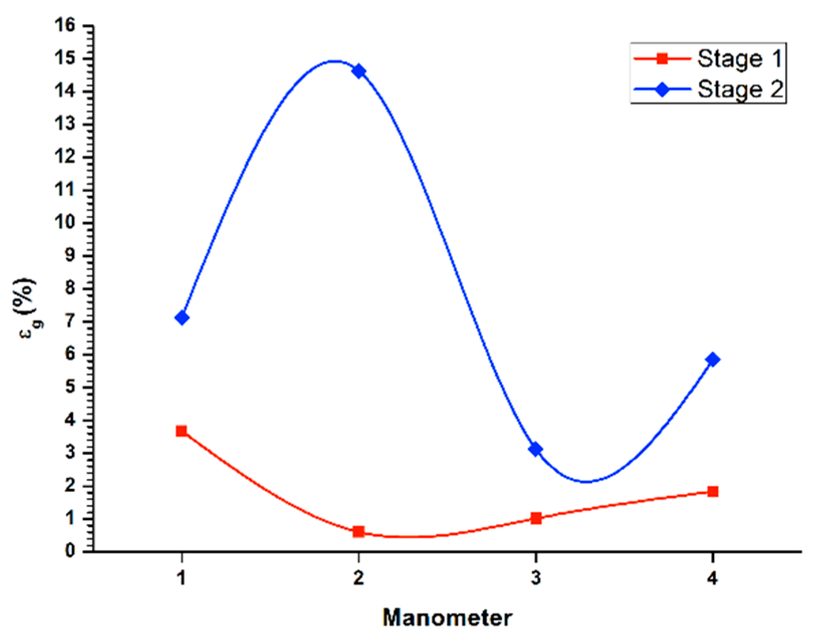
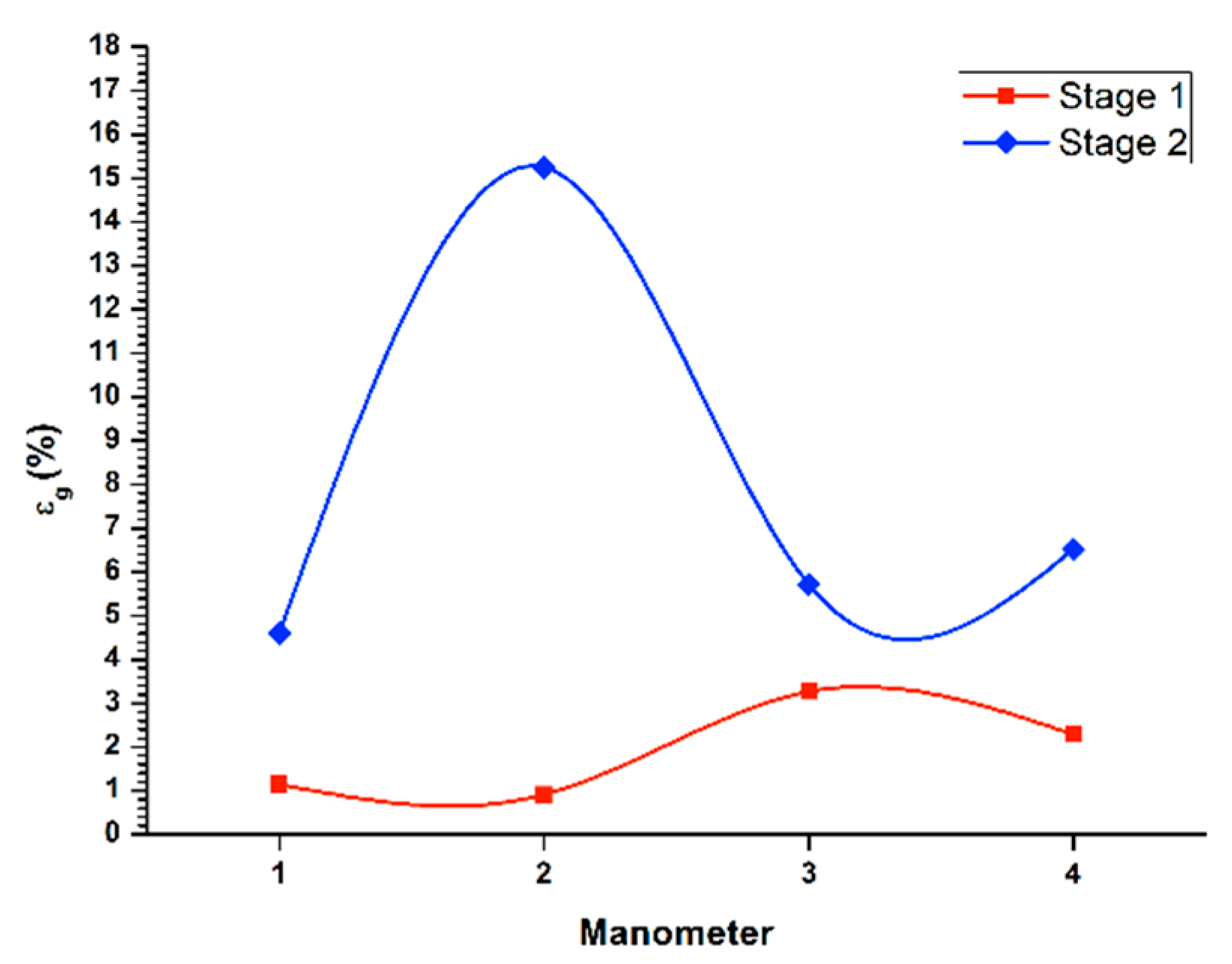
Figure 5 (1st stage line) shows the determination of gas retained in the columnar flotation cell, for the recovery in a batch system through the first cleaning stage, with a flow of liquid in the tail flow (
JLT) of 0.68 cm/s, applying the gas flow (
Jg) of 0.3 cm/s. There was a higher concentration of gas retained in the lower part of the system (manometers 1 and 2), thus creating a low ascent velocity of the bubble pack. Likewise, the middle and upper parts, presented an increase in the speed of ascent of the bubble pack, the middle section being the fastest rise. This makes the bubble pack disperse, increasing the possibility of recovery. Regarding the global retained gas, a value of 1.84% was found, generally giving a higher ascent rate, although with a low bubble concentration that recovered the mineral and with other bubbles of considerable size.
Similarly,
Figure 5 (stage 2 line) illustrates the determination of retained gas (
εg) in the columnar flotation system, for the recovery in the batch system during the second cleaning stage, with a flow of liquid in the tail stream (
JLT) of 0.68 cm/s, applying the gas flow (
Jg) of 0.3 cm/s. In the middle zone of the flotation column (manometers 2 and 3), there was an increase in the concentration of the retained gas. This decelerated the ascent speed, and the recovery decreased, overloading the surface of the bubble with mineral. On the other hand, at the end of the flotation column, low concentrations of retained gas were present, and, therefore, higher rising rates of the bubble package. This result was more evident in the upper part of the column. Concerning global retained gas, a value of 5.9% is shown.
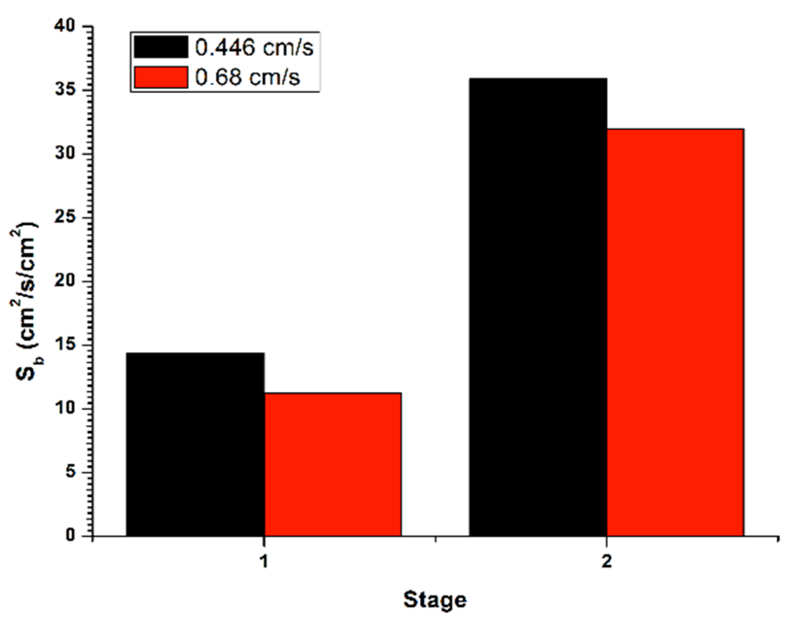
Figure 6 (stage 1) shows the determination of the bubble surface flow (
Sb) from
εg and
Db, for the recovery in batch system, with a flow of liquid in the tail stream (
JLT) of 0.45 cm/s, applying the gas flow (
Jg) of 0.3 cm/s. The bubble surface flow increased between the two cleaning stages, thus generating an increase in gas retained in the system. Such effect was provided by a decrease in the initial bubble size from the first stage to a final one, in the second stage. Moreover, in
Figure 6 (stage 2) is exposed the determination of the bubble surface flow (
Sb) from
εg and
Db, for the recovery in a batch system, with a flow in the stream of tails (
JLT) of 0.68 cm/s, applying the gas flow (
Jg) of 0.3 cm/s. The bubble surface flow increased within the two cleaning stages, thus causing an increase in gas retained in the system. Such effect was provided by a decrease in the initial bubble size from the first stage to a final one, in the second stage. This, in turn, caused a reduction in the rising rate the bubble pack and, accordingly, a lower recovery in the second stage.
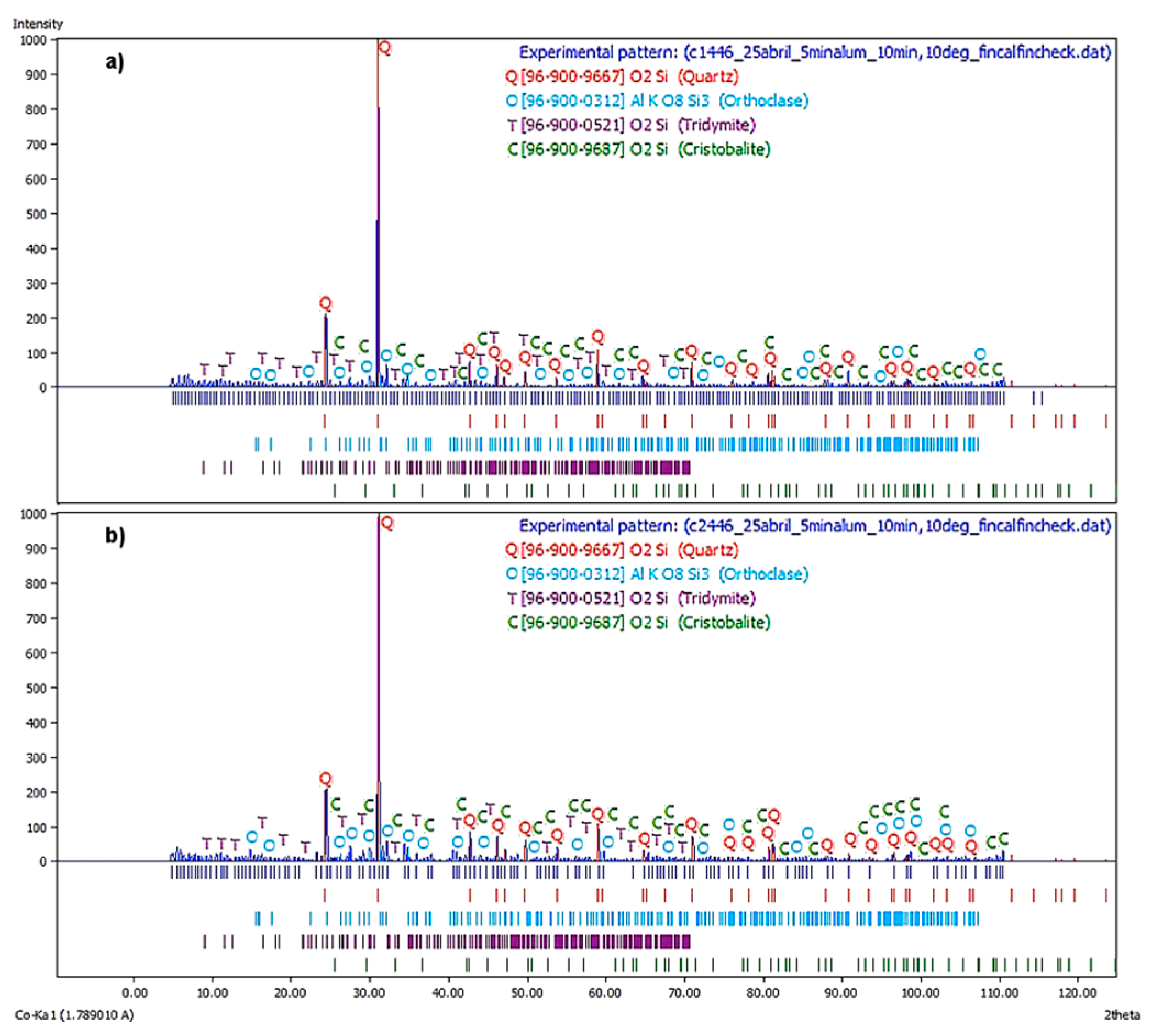
Figure 7a illustrate the X-ray diffractogram corresponding to the first flotation stage at a
JLT = 0.446 cm/s. The major phases are Quartz, Orthoclase, and Tridymite, being the Cristobalite the remaining phase.
In
Figure 7b, the X-ray diffractogram corresponds to the second flotation stage at a
JLT = 0.45 cm/s. It is observed that the principal phases were quartz, orthoclase, and tridymite. The cristobalite was a remaining phase. This spectrum displayed similar behavior to the previous.
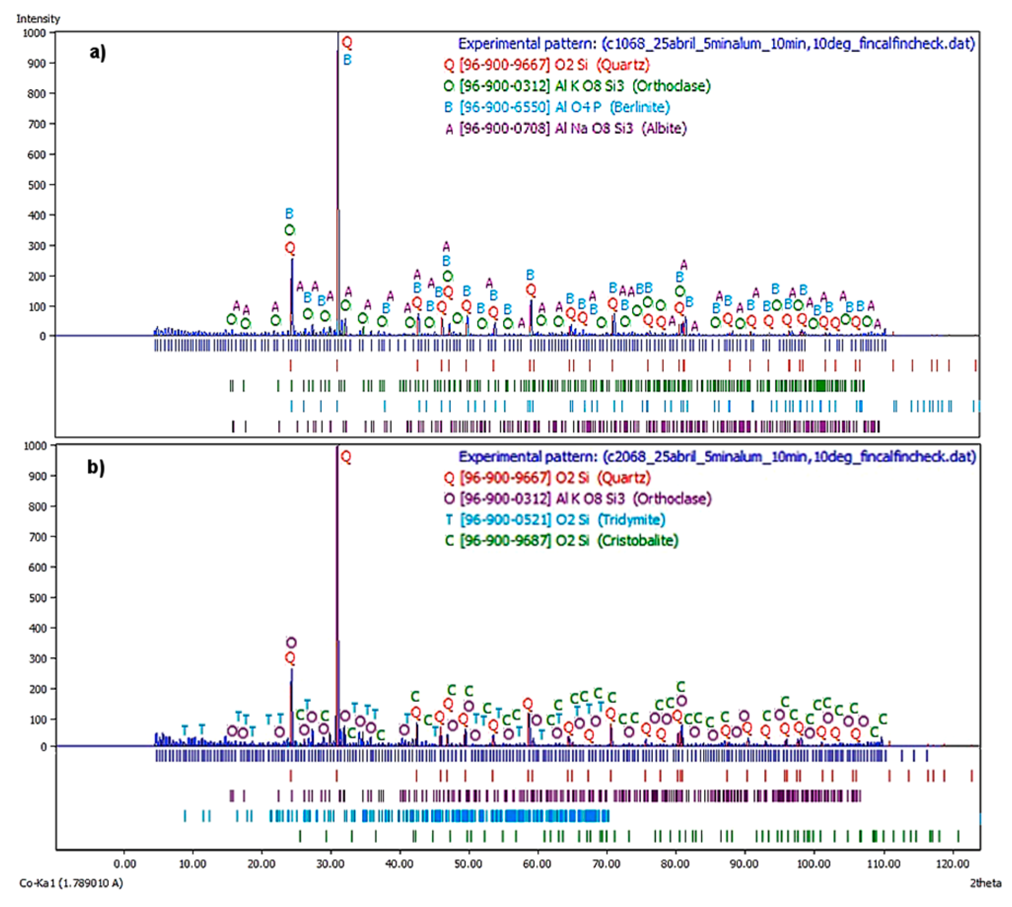
On the other hand,
Figure 8a shows the X-ray diffractogram corresponding to the first flotation stage at a
JLT = 0.68 cm/s. The principal phases were quartz, orthoclase, and berlinite, where the albite was the remaining phase. Note that due to an increase in liquid flow rates, there were more feldspathic phases and a phase analogous to quartz, although the major one was still quartz, concerning the same stage and at a
JLT = 0.47 cm/s.
Figure 8B shows the X-ray diffractogram corresponding to the second flotation stage at a
JLT = 0.45 cm/s. It is observed that the major phases were quartz, orthoclase, and tridymite, while cristobalite was the remaining phase. The behavior was similar to the two stages of the batch process
JLT = 0.45 cm/s.
Regarding the percentages by weight of each phase, it is recognized in
Table 2 that at a lower liquid velocity, a higher concentration of quartz was present. In the second stage at a
JLT = 0.68 cm/s, there was an increase in the level of quartz and orthoclase, cristobalite and tridymite also appearing. This might have happened due to the elimination of albite and berlinite. For flotation at lower liquid velocity, as well as a value of
JLT = 0.45 cm/s, a similar behavior was found between the two stages, since it increased the concentration of allotropic phases of the silica, decreasing the concentration of orthoclase.
4. Discussion
In this work, a flotation column was used for the separation of silica and feldspars from mining waste, since flotation columns have advantages over conventional cells [
18], because they do not use mechanical agitation, they operate with bubbles much smaller than common cells, and with long residence times, an improvement in the degree of recovery is achieved. Similarly, another additional advantage is that flotation columns can treat a large volume of ore, occupying a small area, as well as very fine minerals, at very attractive investment and operation costs [
19,
20].
Consequently, the main disadvantage of the flotation columns lies in their low capacity to recover thick particles [
21], but this is not the case where there is a fine grain size.
Therefore, the use of flotation columns for the recovery of silica and feldspar, offers many advantages, especially in the improvement in grade and recovery for an isochemical mineral like the one studied here.
Due to the need of understanding what happens during quartz flotation, precious studies related to this topic using DDA, showed that flotation radically decrease with sizes from hydrophobic aggregate, which in turn increases with the length of the collector chain [
22]. Similarly, flotation depends more significant on particle and bubble sizes. For instance, when there are small bubbles, high flotation rates can be reached at very low power intensities. On the other hand, when larger bubbles are present, flotation rate increases with increasing of the surface area’s intensity, when both fine and intermediate particle sizes are treated. In addition, an optimal intensity of power was reached for thicker particles, just as is the case found in this work [
23]. In the same way, flotation was not affected by the particle size, although we did the study with fine and thick particle sizes.
For SiO
2 flotation, the influence of ions (type, concentration, and their combination) on the bubble coalescence disclosed that the hydrophobic attraction was reduced with the increase of collector concentration. Due to the decrease in the solubility of the gas phase, the change of the superficial tension and the rheology of the thin liquid film in the gas–water and ion–water interfaces, depending on the hydrodynamic condition (static condition) [
16]. In the case of this study, a low concentration of retained gas was generated. Therefore, a continuous recovery was obtained, due to the existence of a good flux rate, which was generated for the bubble pack, and also due to the minimum concentration of sulphur species and the Fe
2O
3, when using C
12H
25NH
2 as collector, because at low values of
Jg, especially 0.3 cm/s, a concentration of 81.66% was reached joint to a decrease to zero concentration of Fe
2O
3.
Similarly, some researchers [
24] did conventional flotation experiments with a mixture of feldspars and quartz in diluted solutions of hydrofluoric acid (HF), obtaining important recoveries for quartz (95.4% quartz recovery with a global recovery of 88.6%), and a concentration of feldspar of 99.9% (95.9% for albite and 95.5 for microcline). In this work during the batch flotation in column a 75.13% of recovery was reached for all the allotropic phases of silica (quartz, tridymite and cristobalite), and of 24.87% of a feldspathic phase (orthoclase), which is favourable to environment because there is no use of acids, activators and depressants, combined with a low concentration of collecting agents and foaming agents.
Consequently, as is shown in this work, this new concept could be used to produce a quartz concentrate, which also could be of great value as an important stage of cleaning to remove the last remnants of feldspars from the product. In the same way, this process has also probed for recycling porpoises. Some researches [
14] have pointed that the used model for the flotation, are efficient for this kind of processes used for iron minerals waste. Larsen and Kleiv [
24], found that silica was recovered quite successfully from a slag coming from the production of silicon in an electric reduction smelting furnace.
5. Conclusions
In the medium dodecylamine (C12H25-NH2), it was studied the recovery of silica from the waste of the “Dos Carlos” dam, in a batch flotation system with two cleaning stages. The experimental condition considered Jg of 0.3 cm/s, in both cleaning stages, and JLT of 0.45 and 0.68 cm/s, for each one. Similar bubble sizes were obtained for the range of Jg 0.1 to 0.3 cm/s of the effect of JL, generating a similar retained gas concentration and therefore promoting a steady recovery, since there was a comparable rising speed of the bubble pack.
In the characterization by XRD, a particular phenomenon was presented since at a lower surface velocity of the liquid and especially at a JLT value of 0.45 cm/s, an area of the higher collection was introduced in the lower half of the column. So in the batch column flotation, consisting of two stages, 75.13% of recovery was achieved for all the allotropic phases of the silica (quartz, tridymite and cristobalite). This leaves a concentration of 24.87% of a feldspathic phase (orthoclase) as a remnant. Finally, according the obtained results, we can propose the use of the silica obtained in the cement industry, principally.
Feldspar residue with varying amounts of calcium, potassium or sodium [
25,
26], has a low melting point 758 K (485 °C), and it is used in the manufacture of glass, since alumina gives it hardness, durability and resistance to chemical corrosion. The second use of feldspar is in the ceramic industry, where its use as a flux for ceramic vitrification. Similarly, it is known that according to the content of potassium, the greater the amount of it, the material has a better performance as a cementing agent [
27].
The advantage of using feldspar obtained as a byproduct of an epithermal reservoir like the one studied here, offers advantages over one of residual origin; since feldspar of isochemical primary origin is a pure material [
25]. Additionally, the bounded particle size is of importance for the ceramic industry, because the ideal size should be greater than 170–200 meshes (74–88 microns), according to the US Geological Survey [
27,
28]. For this case, the waste material recovered here, exceeds 170 meshes (88 microns), and due to the comminution of the waste is more competent, mechanically. Likewise, due to surface exposure, the secondary feldspar usually has hematite alterations that affect the color of the ceramics and the flux function is modified because the iron is high temperature.
Consequently, recovered feldspars can be considered mixed because of their sodium, potassium and calcium contents. Therefore, its use could be in the elaboration of construction material (tiles, decoration material), abrasives (sandpaper for wood), seed coating, scrubbing soaps. However, this feldspar could be used in white paste and fine porcelain ceramics, but a second flotation would have to be done to remove residual impurities such as iron, since a maximum of 1% Fe is required for this use.
On the other hand, quartz, tridymite, and cristobalite, since they are of primary origin, are usually isochemicals of greater purity, unlike the supergenic quartz of areas of residual sand, due to the great variety of quartz components that are the result of their secondary alteration, such as el, jasper, chalcedony, chert, opal, or other siliceous varieties. This is due to the fact that the chemistry of supergenic quartz is varied and depends essentially on the type of rock affected. Industrial sand and gravel, often called “silica,” “silica sand,” and “quartz sand,” include sands and gravels that are high in silicon dioxide (SiO2). These arenas are used in the manufacture of glass; for hydraulic fracture, fracture, and abrasive applications, mainly.
The chemical composition and physical properties of the silica recovered from the “Dos Carlos” dam, show that it can be used as a raw material for the ceramic industry. Similarly, it can also be an alternative for the cement industry because of its silica content [
29], and for the manufacture of building materials, as well as a substitute for mixed feldspars, in some common applications and uses.
Similarly, silica sand is used as a granular filter medium in the treatment of drinking and wastewater. Because of its hardness, it can be used in the manufacture of sandpaper, industrial abrasives, and blasting sand, in formulas of detergents, paints, concrete, and special mortars, in addition to being the basis for the manufacture of refractories based on silica [
30,
31,
32,
33].

 ,
, 


