1. Introduction
Carbon nanohorns (CNH) represent a type of carbon allotrope also discovered by Iijima in 1999 [
1] which hasn’t received as much attention as other members of the carbon nanoparticle family, such as carbon nanotubes (CNT) or onion-like carbons (OLC).
CNH consist of multiple singlewall nanohorns (SWNH) which have the same tubular body as single wall carbon nanotubes, but instead of being either open-ended or capped, these structures have a horn-like ending with a cone angle of 20°. With a diameter of 4–5 nm at the tubular part SWNH are similar in size to smaller varieties of multi wall carbon nanotubes [
2]. The structural arrangement of SWNH in CNH is similar to that of the needles in a sea urchin and form ball-like suprastructures measuring up to 100 nm in diameter [
2,
3]. Even though CNH are often referred to as aggregates, it remains unclear, whether CNH actually consist of aggregated SWNH or they possess a graphitic core [
4]. Different synthesis techniques and process conditions lead to the formation of multiple subtypes of CNH [
3,
5]. So far, three different types, ‘dahlia-like’, ‘bud-like’, and ‘seed-like’, have been identified each of which differs slightly regarding their morphology from its siblings. A characteristic of dahlia-type CNH are the protruding ends of the horn caps [
6]. As currently only dahlia-type CNH are being synthesized in significant amounts, this type of CNH will be used for this work.
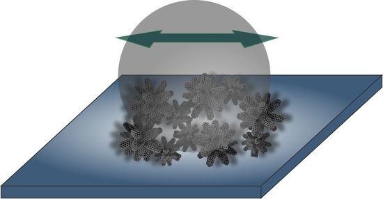
Due to their spherical morphology, CNH may have the ability to roll while separating sliding surfaces in a loaded contact and therefore act as a nanoscale bearing. Similar behavior has been observed with other sp
2 carbon nanostructures (e.g. CNT or OLC), a material class well-known for its ability to reduce friction and wear [
7,
8].
However, specifically for OLC, it has been shown that their lubricity is strongly dependent on the surface finish of the supporting substrate [
9]. This is a consequence of their small size (diameter < 5 nm), which renders them prone to be stored within the surface grooves, avoiding their positioning between the contacting surfaces. For CNH, this would not be a defining factor, since their size and morphology would allow them to be dragged into the contact.
Combining this with the mechanical strength of sigma bonds stemming from the sp2 hybridized carbon frame, CNH have a high potential as solid lubricants in dry sliding.
To the best of our knowledge, no experimental studies on the mechanical properties of CNH have been conducted so far. However, simulations carried out by Jordan et al. aimed at predicting the mechanical response of single- and two-pentagon graphene cones when subjected to vertical indentation at its apex [
10]. The model predicts a mechanical behavior initially following the elastic Hooke’s law. Once a critical energy is exceeded, the cone buckles inwards, leading to the formation of a fold. With continuing indentation, the mechanical response transitions into a state known as constant-force mode during which elastic energy is stored in the fold. Eventually, further compression leads to a complete inward inversion of the cone. Described mechanism is entirely reversible and gives CNH the potential to absorb a significant amount of mechanical energy.
Tanaka et al. studied the friction and wear reducing properties of CNH as reinforcement phase in polyimide-based composites and came to the conclusion that an addition of 5 wt % of CNH to the composite reduces the specific wear rate by two orders of magnitude [
11].
In previous reports, the differences between carbon nanoparticles and graphite have been discussed extensively. The most significant difference is that graphite only lubricates when the relative humidity exceeds a threshold value, whereas the closed carbon nanoparticles do lubricate in dry environments as well. The key aspect is the fact that the nanoparticles can roll/glide [
12] between the contacting surfaces as opposed to graphite which depends on the intercalation of water molecules [
13] to reduce the shear strength between the consecutive graphene layers. Another important feature is that, graphite is a product of the carbon nanostructure degradation. Finally, due to the lack of edges, CNH are less susceptible to oxidation which means that CNH could theoretically lubricate at higher temperatures and also in vacuum. In summary, we believe that the lubrication properties of CNH are much less dependent on its surroundings compared to current solid lubricants and could have a much wider range of applications.
The objective of this work is to research and understand the friction and wear behavior under dry sliding of CNH coatings deposited on steel substrates. In order to examine the lubrication properties of such a coating, dahlia-type CNH will be deposited onto a steel substrate by the use of electrophoretic deposition (EPD).
EPD is a well-studied and simple technique allowing for the deposition of particles with a surface charge onto conductive substrates [
14,
15]. In the case of carbon nanoparticles, the presence of oxygen-containing functional groups such as carboxylates provides a negative surface charge which enables the deposition in the first place [
14,
16,
17]. EPD has been used in the past to form heterogeneous and uniform carbon nanoparticle coatings [
14,
15] which act as solid lubricant [
18,
19] or provide protection from either mechanical impact or corrosion [
19].
2. Materials and Methods
2.1. Materials
Dahlia-type CNH synthesized by sublimating graphite were purchased at Carbonium SRL (Italy). According to the manufacturer, the single nanohorns measure 30–50 nm in length and 2–5 nm in diameter.
Single CNH clusters as depicted in
Figure 1a are of spherical shape with individual horns protruding to the outside. The aggregated clusters shown in
Figure 1b measure anywhere between 35 nm and 220 nm in diameter. Austenitic stainless steel platelets (AISI 304, 20 by 20 by 1 mm
3) with a mirror-polished surface finish were used as substrate.
2.2. Particle Dispersion and Deposition
First, steel platelets were thoroughly cleaned in order to remove any type of contaminants from the surface. Each platelet was sonicated for 10 min consecutively in cyclohexane then acetone and finally isopropanol.
The deposition solution consists of 80 mL of isopropanol, 0.05 mg mL−1 CNH, 0.5 mL of deionized water, and 0.0125 mg mL−1 of magnesium nitrate hexahydrate. Small amounts of deionized water were added to support the formation of a Mg(OH)2 holding layer.
The process of dispersing CNH in the solution consists of two consecutive steps. First, the solution undergoes shear mixing in an IKA T25 for 10 min at 12 k rpm. Subsequently, the solution was placed in an ultrasonic bath (Bandelin sonorex super RK 514 BH, 35 kHz-860 W), again for 15 min.
Two steel platelets serving as electrodes are partially immersed in the solution and connected to a DC voltage source (Consort EV3020, 0–300 V, 0–2000 mA, 0–300 W). Inter-electrode distance was kept constant at 1.3 cm. EPD was conducted at 300 V for 15 min.
2.3. Tribological Experiments
During this study, a CETR-UMT ball-on-disc tribometer (Bruker, Billerica, MA, USA) was used under dry sliding conditions in linear reciprocating mode and a stroke length of 0.6 mm. The tribological measurements were conducted under a normal load of 0.1 N, 1 mm s−1 sliding speed and a humidity of 7 ± 2% in order to exclude graphite lubrication. Al2O3 balls measuring 6 mm in diameter with a surface roughness Rrms = 55.5 ± 12.8 nm (determined by white light interferometry, 12 measurements) were used as counter body.
2.4. Raman Characterization
Raman characterization was conducted with a spectrometer from Renishaw (Wotton-under-Edge, UK) using an excitation wavelength of 532 nm. For each sample, measurements were taken at three different points with three accumulations at 0.5% laser power and 2400 mm/lines grating. Furthermore, the background was removed from the raw data and each of the peaks was fitted and subsequently analyzed with a Lorentzian curve.
2.5. Chemical Characterization and Wear Track Analysis
A SEM/focused ion beam (FIB) Helios Nanolab 600 dual beam station (FEI, Hillsboro, OR, USA) with integrated energy dispersive X-ray spectroscopy (EDX) was used to take the SEM images and investigate the wear tracks. An acceleration voltage of 5 kV and a current of 1.4 nA was used. EDX was performed to analyze the chemical composition of the surface at 15 kV and 11 nA.
3. Results and Discussion
3.1. CNH Coating Characteristics
As shown in
Figure 2a, the top view of the coating depicts a compact, homogeneous covering of the surface with the presence of some cracks which are more clearly visible at higher magnification in
Figure 2b. These might be a consequence of the high voltage deposition and the dimensional changes during drying.
The thickness and the sub-superficial features were characterized by performing a FIB cross section of the CNH deposition which is shown in
Figure 2c. The individual CNH particles seem to be forming elongated aggregates which are stacked on top of each other. This sort of arrangement leaves plenty of space between the aggregates, hence a foam-like structure with significant void volume can be identified. Their connection is predominantly of electrostatic nature (π–π interaction) and very weak, which is desired in lubrication applications as it allows for free rolling and/or gliding of the individual particle and therefore, theoretically, a behavior equivalent to that of a bearing.
Directly at the uppermost region of the CNH deposition, the packing density of the aggregates is clearly higher due to compression by the Pt protective coating. In order to avoid such compression, the average thickness of the coating was measured by laser scanning microscopy at three different spots and yields a value of 5.3 ± 0.7 µm.
The fact that CNH were able to be deposited by EPD vouches for the presence of oxygen-containing functional groups, which play a fundamental role in this deposition technique as they form a negative surface charge in solution. When adding magnesium nitrate hexahydrate as an additive, the magnesium cations attach to the negative surface groups, which leads to a reversal of the surface charge. This is further confirmed by the fact that the deposition was formed on the cathode (cathodic EPD). The deposited particles measure 70–100 nm in diameter.
3.2. Frictional Behavior
Figure 3 shows the temporal evolution of the coefficient of friction (COF) both, the CNH-coated steel substrate (CNH) and an uncoated polished steel reference (Ref) over a time period of 13,000 s. At the beginning of the test, the asperities on the surface of both friction partners only allow for a small contact area therefore in both cases, the initial COF is low.
The COF of the reference increases to 0.75 within the first 500 s. After that, the COF decreases slightly down to 0.70 and gradually climbs from there up to around 0.79 where it enters the steady state after approximately 4000 s. The shape of the run-in region is in good agreement with one of the curves proposed by Blau [
20], where the removal of surface oxide combined with plastic deformation of the metal substrate is responsible for the formation of the first peak. Dislocation density increases as a consequence of the plastic deformation and leads to work hardening which explains the following COF decrease. The second increase is likely to be caused by abrasive debris [
20]. The remaining asperities are worn off rapidly as the alumina counter body indents deeper into the substrate. Subsequently, the contact area further increases and along with it, the COF. The value of the steady state COF for the metal-ceramic contact agrees with those reported previously in the literature [
21].
The CNH coating shows a different tribological behavior when compared to the reference. At the initial stages of the test, its COF decreases right away and reaches a minimum between 0.13 and 0.14 after roughly 650 s. After 2300 s, the COF starts to increase steadily over the subsequent 9500 s during which the dispersion in the COF values is considerable. As reported in a previous paper [
19], the use of Mg-Nit as additive during EPD leads to the formation of a Mg(OH)
2 layer between the steel surface and the CNH deposition. This holding layer first described by Santhanagopalan et al. [
22] has the ability to mechanically incorporate parts of individual CNT thus pinning the particles and holding them in the contact area where they provide lubrication. As CNH are composed of individual single wall CNT, it is probable that the same anchoring mechanism is occurring. However, the formation and distribution of the aforementioned holding layer is not uniform. Consequently, once the weakly-bound superficial CNH are removed from the contact and the region where the holding layer acts is reached, the frictional behavior is dominated by the CNH-holding layer interaction, rendering a very unstable evolution. Eventually after approximately 12,000 s, the COF enters steady-state behavior. This gradual increase indicates a progressive removal of CNH from the contact area until most particles are removed from the contact area and the contact situation turns into that of a metal-ceramic system.
According to Aouadi et al. [
23], an effective lubrication is given at a COF < 0.2 which, in the case of the CNH coating, is retained for almost 3000 s or roughly 50 min. Minimum COF values between 0.13 and 0.14 were obtained which surpasses the values measured for carbon nanotubes tested under comparable conditions by MacLucas et al. [
19] and Reinert et al. [
18] where, in both cases, the minimum COF was around 0.18.
3.3. Wear Track Analysis
The wear track analysis shows very different morphologies in both studied systems.
Figure 4a depicts a representative scar resulting from sliding against the metal reference. In this case, the main wear mechanism is evidently adhesion, resulting from the solid-state welding during contact. Furthermore, the difference in contrast within the scar is a consequence of tribologically-activated oxidation. On the other hand, the CNH-coated sample (
Figure 4b) shows a similar morphology as the reference after the test, with evidences of adhesive wear. However, there are two features that differentiate the CNH-coated sample from the metal-ceramic system. First, an accumulation of swiped material at the ends of the track is clearly noticeable. Second, the internal region of the track does not show very strong contrasting and certain regions do not seem to be significantly affected (e.g. the right end of the track). Hence, the main difference between both systems seems to be that the reference state reaches a severe wear stage earlier than the CNH-coated samples. This delay is clearly associated to the retardation of the metal-ceramic interaction by the presence of the CNH deposition. Simultaneously abrasive particles stemming from both surfaces are formed in the contact area which enhance and accelerate wear.
3.4. Chemical Characterization
To further understand the interaction and tribo-chemistry during sliding, elemental distribution maps of the wear tracks were acquired.
Figure 5 shows a set of chemical maps of oxygen (b) and iron (c) of the reference wear track. From
Figure 5b it is evident that the internal region of the scar is strongly oxidized. This stems from the accelerated oxidation kinetics during sliding contact [
24]. It is worth mentioning that no aluminum signal was detected, meaning that no material transfer from counter body to substrate has occurred.
As expected, iron (
Figure 5c) is detected inside of the wear scar as well, indicating that a significant amount of the oxide formed is iron oxide.
Figure 6 consists of elemental maps of the wear track from the CNH-coated sample. Here, oxidation is also noticed but limited to a smaller region. Furthermore, the piled-up material on the edges of the track consists mainly of oxide particles. The very low carbon concentration within the wear track (
Figure 6c) further supports the assumption about the complete carbon removal, explaining the high final COF. As expected, since there is no hindering for the carbon removal, after a certain amount of sliding cycles, the CNH lubrication is gone and the system behaves as in the reference state. The distribution of the detected magnesium depicted in
Figure 6d coincides with the same areas as the carbon, confirming the assumption that already during EPD, the magnesium is mainly attached to the carbon nanoparticles. Additionally, as already mentioned, once the reference COF is achieved, it is certain that the original Mg(OH)
2 holding layer has been rubbed away.
3.5. Solid Lubricant Structural Analysis
For the structural analysis after the friction experiment, three positions were chosen (as indicated in
Figure 7a, namely: (I) central position in the internal region of the track, (II) edge of the internal region of the track and (III) on the CNH coating.
The spectrum of region I (
Figure 7b) confirms the hypothesis that the oxide formed during sliding was iron oxide, as observed from the chemical maps. Regarding the lubricant itself, the assessment of the CNHs’ structural state will be based on the most widely used qualitative indicators for sp
2 hybridized carbons, which are: The defect index (I
D/I
G) [
25], the purity index (I
G’/I
D) [
26], the full width at half maximum of the G-band (w
G) [
27], as well as the G-band position (X
CG) [
28]. The latter two indicators are mainly related to the crystalline state (domain size and amorphisation state) of the carbon structure. The corresponding data is listed in
Table 1.
The Raman characteristics of both, pristine and deposited CNH, show two main disparities.
The first one is the difference in the I
D/I
G ratio. The value of the pristine CNH is 0.89, whereas the corresponding value for the CNH outside the tribological contact zone is 1.05. This difference between the two states can be traced back to the fact that prior to electrophoretic deposition, CNH must be dispersed in a solvent. During this step, the particles are exposed to shear forces as well as ultrasonication. The latter in particular is known to be able to cause structural damage to the closely-related multiwall CNT [
29]. The highest defect index is, as expected, observed for the spectrum acquired inside the wear track and vouches for a mechanical degradation of the carbon structure stemming from the tribological contact.
The second major distinction can be observed at the G’-band around 2660 cm
−1 where pristine CNH generate a stronger signal. At 0.34, the resulting purity index of deposited is lower than the one of pristine CNH (0.53). The amount of impurities should rather decrease during dispersion and especially deposition as only negatively charged particles are attracted by the anode. However, as has been shown in a previous study [
19], when Mg-Nit is used as an additive, after EPD, the magnesium ions remain on the surface attached to the CNT which possibly affects the Raman interaction.
The remaining two qualitative indicators do not show significant variations. Considering the spectral resolution of the spectrometer under the chosen configuration (1.2 cm−1) both parameters of the pristine CNH do not deviate from deposited CNH or even tribologically affected CNH, therefore no significant change in crystallinity was determined.
Furthermore, the G-band positions of all analysed states are very similar, indicating that no significant overall structural change has occurred regarding the crystallite size. However, in all states the G-band is located at 1588 cm−1 instead of 1581 cm−1 (which is typical for graphitic structures). This might be related to the presence of the D’-band (at approximately 1620 cm−1), which is associated to the short range order of these small structures. Hence, when analysing the degradation of CNH during sliding, it would be recommendable to focus the analysis on the D-band evolution, since it seems to be more sensitive to disorder and degradation in these structures than wG and the G-band position.
4. Conclusions
To the best of our knowledge, a homogeneous CNH coating has been successfully deposited from solution onto a stainless steel substrate via electrophoretic deposition for the first time.
Structural analysis revealed that the dispersion process causes the defect density in the CNHs’ structure to increase. Exposing CNH to tribological stress increases the particles’ ID/IG ratio even more due to mechanical degradation. At the same time, the purity of the particles decreased due to the attachment of magnesium ions to the carbon as well as wear byproducts.
Furthermore, the tribological properties of a CNH coating were investigated and the predicted lubrication ability was proven. Compared to the uncoated reference, an initial friction reduction of 83% was achieved. Under chosen specific conditions, CNH are able to provide effective solid lubrication for an extended period of time. Likely, this is related to the morphology of the particles. CNH have the ability to roll in all directions whereas CNT do not. In addition to that, the CNHs’ morphology leads to a lower reagglomeration probability when compared to CNT, likely as a consequence of reduced effective contact surface.
In summary, CNH represent promising candidates for tribological applications as solid lubricants, even at low humidity levels as opposed to conventional solid lubricants (e.g., graphite).


