Article

Numerical Study of Power Loss and Lubrication of Connecting Rod Big-End

Department of Mechanical and Aerospace Engineering, Politecnico di Torino, 10129 Torino, Italy
*
Author to whom correspondence should be addressed.
Lubricants 2019, 7(6), 47; https://doi.org/10.3390/lubricants7060047
Submission received: 10 April 2019 / Revised: 19 May 2019 / Accepted: 29 May 2019 / Published: 1 June 2019
(This article belongs to the Special Issue Tribology of Powertrain Systems)

Abstract

:
A hydrodynamic lubrication analysis for connecting rod big-end bearing is conducted. The effects of engine speed, operating condition, lubricant viscosity and oil temperature on tribological performance of big-end bearing have been examined. Force equilibrium is solved to define instantaneous eccentricity between journal and bearing to have accurate estimation of oil film thickness at interface of connecting rod big-end bearing and crankpin. Connecting rod big-end is treated as π film hydrodynamic journal bearing and finite difference scheme is applied to calculate generated hydrodynamic pressure and frictional power loss at each crank angle. Beside the development of analytical formulation, well-known Mobility model introduced by Booker has been employed to be compared with the analytical model. The presented analytical model reduces the complexity and the numerical effort with respect to Mobility method, thus shortening the computation time. The simulation results show good agreement between analytical model, Mobility approach and experimental data.

1. Introduction

The primary purpose of hydrodynamic bearings is to support a rotating shaft and to guaranty the hydrodynamic lubrication at bearing surfaces interface. Journal bearings are one of the most common types of hydrodynamic bearing. They can be found in various subsystems of reciprocating engines and powertrains. Connecting rod big-end bearing is the one form of journal bearings. Journal bearings are designed to operate under hydrodynamic lubrication. This is under influence of applied load and relative motion of bearing components that create hydrodynamic wedge and consequently hydrodynamic pressure within the oil film to stand against the applied load. The formed hydrodynamic pressure at the journal and bearing junction is typically distributed over half of the journal/bearing interface, but also this hydrodynamic pressure distribution can be limited to small fraction of the bearing area under severe conditions. The magnitude of the hydrodynamic pressure at journal/bearing interface is influenced by the film thickness in which the amount of available oil is a function of initial clearance and instantaneous eccentricity between centres of the lubricated pairs [1,2,3].
Frictional power loss reduction at reciprocating and rotating lubricated components is recognised as a promising way to improve internal combustion engines (ICEs). Experimental observation is the most adopted approach to investigate the tribological performance of lubricated reciprocating and rotating bearing couples which brings some disadvantages such as being costly and time-consuming as well as varying from case to case. In contrary, analytical and numerical investigations shorten the observation time, reduce cost and can achieve a reliable representation of the real system behavior, providing opportunity to study the effect of influential parameters [4,5].
In 1965 Booker presented an analytical, graphical and numerical approach to simplify the solution for general problems associated with dynamically loaded bearings, so called Mobility Method [6]. The method is not based on the particular solution for Reynolds equation. Six different cases considering fully and partially lubricated journal bearings have been considered and solutions are discussed. Later the author [7] reversed the method and provided more numerical details, which are applicable for reciprocating engines.
The Mobility Method is frequently applied to evaluate dynamically loaded journal bearings. Curve fitting of eccentricity of journal bearing is a part of the method, which is affected by solution accuracy and the required details and time. A set of analytical curve fits was introduced including two components of mobility vectors, location and magnitude of maximum film pressure, as well as the starting and finishing angles of the pressure curve. From accuracy and solution detail aspects, the approach is comparable with finite-element analysis but with a computation time comparable to that required for the short bearing approximation [8].
The dynamic behaviour of an elastic connecting rod bearing was evaluated and the performance of two different bearings of a petrol and a diesel engine were compared [9,10]. Instantaneous elastic deformations and pressure distribution were calculated for different values of the load.
Hirani et al. [11], based on the Mobility Method [6], proposed a closed form pressure distribution over dynamically loaded journal bearings, applying combination of short and long bearing approximations. Determination of start and end points of positive pressure at journal/bearing interface can be defined through simple analytical equations, and simplifies the application of Mobility Method. The model encourages the estimation of instantaneous maximum pressure and its angular location.
Paranjpe [12] incorporated the non-Newtonian effect in a general way to detailed analysis of dynamically loaded finite journal bearings. Oil viscosity was expressed as function of shear rate and the effects of shear thinning and viscoelastic properties were taken into account.
Later in 2006, Livanos and Kyrtatos [13] applied the method introduced in [11] to determine the instantaneous hydrodynamic pressure acting on the journal and to calculate friction force and power loss contributed by fluid shear stress ( τ ).
An analytical solution of Reynolds equation for isothermal finite length journal bearings was intended using regular perturbation method [14]. The model relied on the modification of the Ocvirk number as an expansible parameter [15].
Recently, an approach to solve Reynolds equation to evaluate the lubrication of plain journal bearing with finite length has been applied to determine the impedance forces of the fluid film in closed form analytical expression [16]. The model evaluates design parameters such as eccentricity ratio, location of the minimum fluid film thickness, location of the maximum pressure, stiffness and squeeze action coefficients.
The effects of nonlinear suspensions of a rotor bearing system on the bearing dynamic response have been studied considering short bearing approximation. The complex dynamic responses of the rotating system components were detected using numerical simulations [17].
Constantinescu’s theory was employed to develop a full extended Reynolds equation to evaluate tribological performance of finite length bearings considering laminar and turbulent regimes [18]. The effects of both convective and temporal inertia have been examined without consideration of the normal thin film assumption. The nonlinear contribution of convective inertia terms to damping characteristics of radial bearings was evaluated.
The present study was designed to determine the effect of influential parameters such as engine speed, operating condition, lubricant viscosity and temperature. An analytical tribology model was developed to gain insight into connecting rod big-end bearing and crankpin lubrication mechanism. Force balance and Reynolds equation were solved to calculate instantaneous eccentricity of bearing pairs to obtain accurate oil film thickness at big-end and journal interface. Finite difference scheme has been used to calculate generated hydrodynamic pressure and power loss. Mobility method presented by Booker [6,7] was employed to be compared with the proposed model.

2. Model and Procedure

It is common to make some assumptions during analytical modelling and numerical simulation to simplify problems. Following assumptions have been made during model development procedure:
  • Lubricant is assumed to be Newtonian and incompressible, therefore oil density remains unchanged;
  • Lubricant is treated as an iso-viscous fluid;
  • Oil flow is assumed laminar;
  • Hydrodynamic lubrication has been considered at connecting rod big-end and crankpin interface;
  • There is no slippage at the boundaries;
  • Elastic deformation of bearing surfaces has been neglected.
To evaluate the tribological performance of connecting rod big-end bearing, some steps have been taken. To calculate frictional power loss it has prime importance to define the magnitude and direction of forces acting on big-end bearing and journal with respect to the crank angle.

2.1. Connecting Rod Big-End Loads

At each time instant or crank angle, the applied load acting on a big-end bearing can be regarded as contribution of combustion chamber gas force and inertial imbalances due to reciprocating and rotating masses. Three further simplifications are necessary to have a quick estimation of connecting rod big-end tribological performance. Firstly, the imposed loads on the big-end are analysed for a single cylinder and can be applied as an approximation to a multi-cylinder engine [1]. Secondly, the elements are treated as rigid bodies and there is no elastic deformation associated with them. For the last, the dynamic effects of engine fluctuations caused by firing order and inertial imbalances can be confined to few harmonics.
The forces acting on connecting rod big-end due to gas force, F g a s , and induced by rotational and reciprocating inertial forces, F r o t and F r e c , respectively can be calculated through the following equations:
F g a s = p g a s π D 2 4
F r e c = ( m p i s + m p i n + m c r , a ) a p i s ( m p i s + m p i n + 0.3 m c r ) a p i s
F r o t = m c r , r ω c r 2 r 0.7 m c r ω c r 2 r
where D is the bore, r the crank radius, m p i s the piston mass, m p i n the wrist pin mass, m c r , a the connecting rod upper mass, m c r the connecting rod mass, m c r , r the connecting rod rotating mass, ω c r the connecting rod big-end rotating speed, and a p i s the piston acceleration.
The piston acceleration can be expressed as:
a p i s = ω 2 r cos θ sin θ Λ sin θ δ 1 Λ sin θ δ 2 + Λ cos 2 θ 1 Λ sin θ δ 2 + Λ cos 2 θ Λ sin θ δ 2 1 Λ sin θ δ 2 3
where ω is the engine spin speed, Λ = r / l the elongation ratio (with l the connecting rod length), δ = z o / l the offset parameter (with z o = z o c + z o w p the overall offset contributed by crankshaft offset z o c and wrist-pin offset z o w p ), and θ the crank angle.
Regarding to Figure 1, the connecting rod big-end rotating speed can be computed as follows:
sin β = r sin θ z o l = Λ sin θ δ
cos β = 1 sin 2 β = 1 ( Λ sin θ δ ) 2
ω c r = d β d t = ω Λ cos θ cos β = ω Λ cos θ 1 ( Λ sin θ δ ) 2
Thus, the net load W acting on the bearing is:
W = F g a s + F r e c F r o t cos θ

2.2. Reynolds Equation for Bearing Analysis

Generated hydrodynamic pressure at connecting rod big-end bearing can be governed by 2D Reynolds equation as expressed by:
R j 2 α ( h 3 p α ) + x ( h 3 p x ) = 6 η U h R j α + 12 η h t
where x is the coordinate parallel to the journal axis, α the journal circumferential coordinate, R j the journal radius, η the lubricant dynamic viscosity, and U the velocity of entraining motion in rotation direction of the journal that can be defined using:
U = 1 2 ( ω c r + ω j ) R j = 1 2 ω Λ cos θ 1 ( Λ sin θ δ ) 2 + ω R j
where ω j is the crankpin spin speed, assumed to be equal to the engine spin speed ω .
In this study connecting rod big-end and the crankpin are treated as rigid body, and the radial and tangential bearing displacement have been neglected, therefore classical film thickness expression has been used [1,9]. Therefore, the instantaneous oil film thickness h ( x , α ) at bearing surfaces interface can be expressed as:
h ( x , α ) = c ( 1 + E cos α )
where c is the clearance, and E = e / c the ratio of eccentricity between bearing bodies axes to clearance.
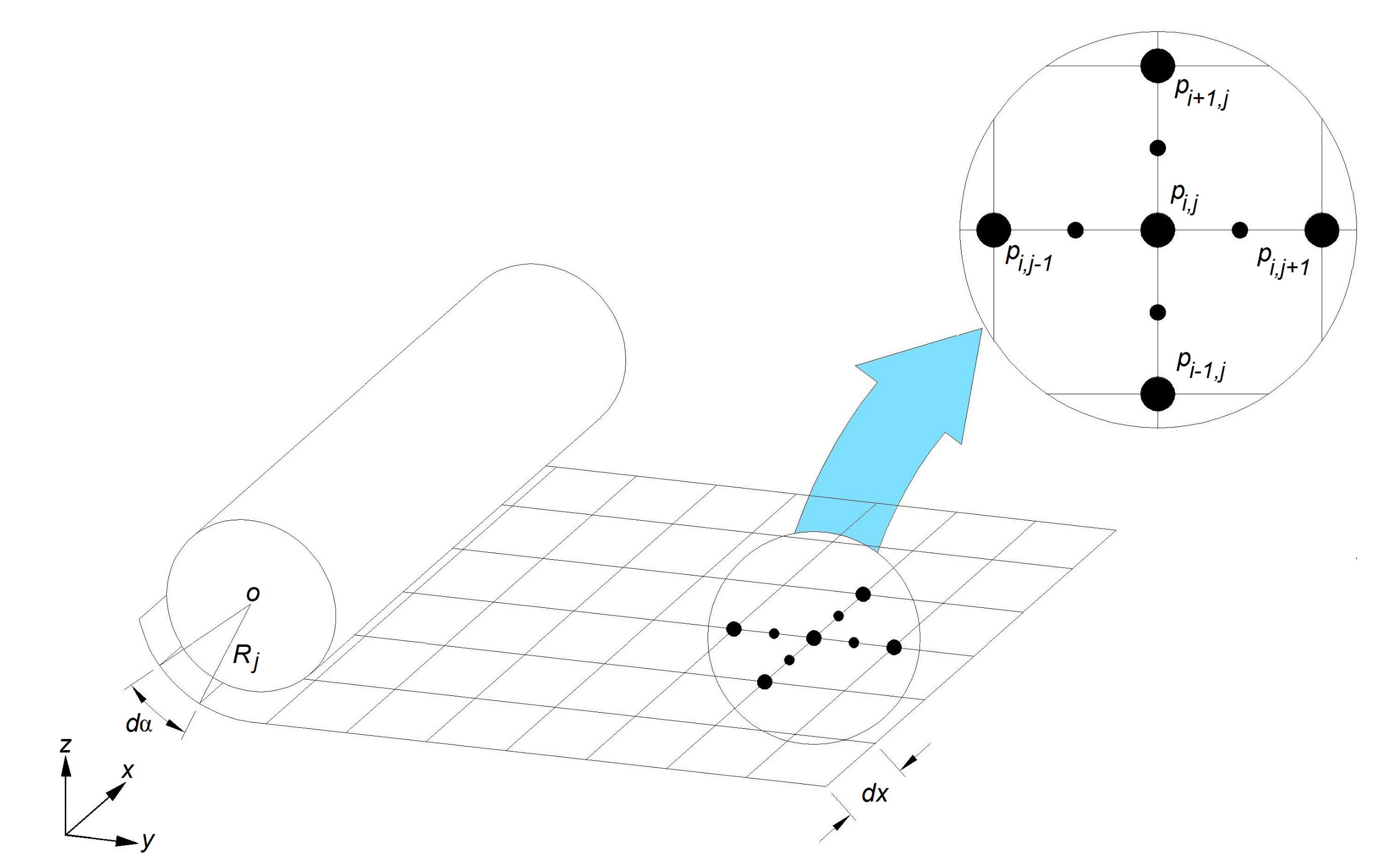
Finite difference scheme can be applied to solve 2D Reynolds Equation (9) and determine the pressure distribution at journal/bearing interface, with a finite difference mesh defined over the journal as shown by Figure 2.
h i + 1 2 , j 3 p i + 1 , j p i , j Δ x h i 1 2 , j 3 p i , j p i 1 , j Δ x Δ x + 1 R j 2 h i , j + 1 2 3 p i , j + 1 p i , j Δ α h i , j 1 2 3 p i , j p i , j 1 Δ α Δ α = = 6 η U h i + 1 2 , j h i 1 2 , j Δ x + 12 η ω h i , j θ + Δ θ h i , j θ Δ θ
Re-equating Equation (12) yields the hydrodynamic pressure at each node p ( i , j ) with respect to adjacent nodes:
p ( i , j ) = a 2 a 1 p i + 1 , j + a 3 a 1 p i 1 , j + a 4 a 1 p i , j + 1 + a 5 a 1 p i , j 1 6 η U a 6 a 1 12 η ω a 7 a 1
where
a 1 = h i , j + 1 + h i , j 2 3 R j Δ α 2 + h i , j + h i , j 1 2 3 R j Δ α 2 + h i + 1 , j + h i , j 2 3 Δ x 2 + h i , j + h i 1 , j 2 3 Δ x 2 a 2 = h i + 1 , j + h i , j 2 3 ( Δ x ) 2 a 3 = h i , j + h i 1 , j 2 3 ( Δ x ) 2 a 4 = h i , j + 1 + h i , j 2 3 ( R j Δ α ) 2 a 5 = h i , j + h i , j 1 2 3 ( R j Δ α ) 2 a 6 = h i , j + 1 + h i , j 1 2 R j Δ α a 7 = h i , j θ + Δ θ + h i , j θ 2 R j Δ α
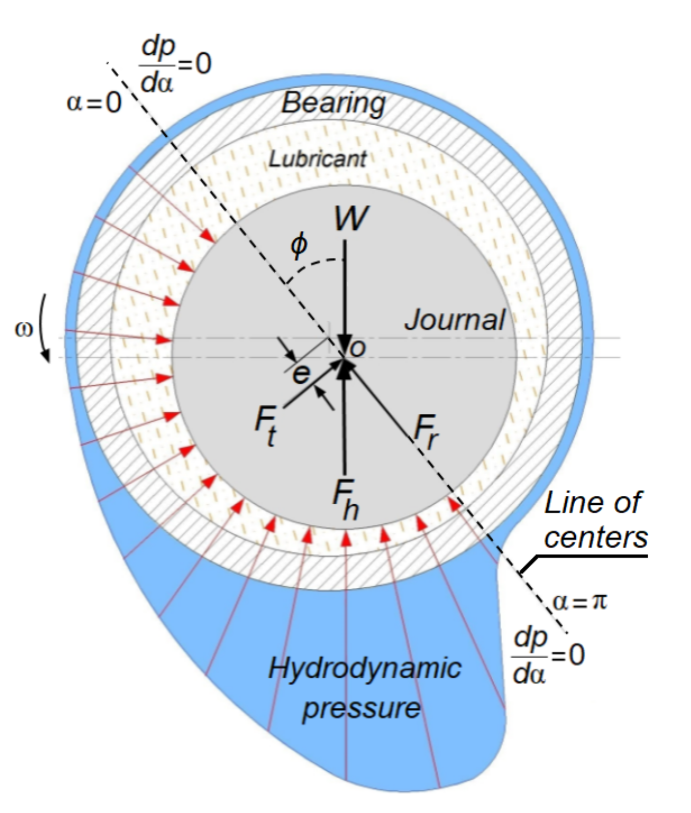
Boundary conditions that must be applied during computation are saturation pressure (crankcase pressure assumed equal to atmospheric pressure) at each edge of the journal, and d p / d α = 0 at each side of the line of centres (Figure 3) as follows:
p = p a t m x = ± L x 2 d p d α = 0 α = 0 , π
where L x is the journal length.

2.3. Numerical Solution

To apply finite difference scheme to calculate hydrodynamic pressure at bearing surfaces interface, it is necessary to define the instantaneous eccentricity between connecting rod big-end and crankpin axes to update the oil film thickness at each time instant (i.e., crank angle).
The following dimensionless quantities have been applied to form an appropriate scale to dimensionless Reynolds equation and oil film thickness expressions:
x ¯ = x L x , h ¯ = h c , θ = ω t , U ¯ = U R j ω , R ¯ = R j R j L ¯ = L x R j , p ¯ = c 2 6 η ω R j 2 p , W ¯ = c 2 6 η ω R j 3 L x W
Applying parameters (15) to Equations (9) and (11), the following dimensionless forms of Reynolds equation and oil film thickness expression are obtained:
α h ¯ 3 p ¯ α + R j 2 L x 2 x ¯ h ¯ 3 p ¯ x ¯ = U ¯ h ¯ α + 2 h ¯ θ
h ¯ ( x , α ) = ( 1 + E cos α )
Knowing that terms on the left side of Equation (16) are pressure terms, it can be re-written as:
p ¯ = U ¯ 1 + R 2 L x 2 h ¯ α + 2 1 + R 2 L x 2 h ¯ θ
Substituting Equation (17) in Equation (18) and performing the derivatives, the expression of hydrodynamic pressure can be obtained:
p ¯ = U ¯ K E sin α + 2 K E ˙ cos α
where K = 1 + R 2 / L x 2 , and E ˙ = e ˙ / ( c ω ) which is the relative linear velocity of the journal and the bearing.
Instantaneous force equilibrium (Figure 3) is applied to define the eccentricity between two bearing surfaces as:
W F h = 0
where the net load W acting on the bearing is expressed by Equation (8), and F h is the hydrodynamic lifting force acting on the journal.
According to Figure 3, F h is the resultant of radial and tangential components, F r and F t respectively, that can be calculated as:
F r = 0 π L x 2 L x 2 p ( x , α ) R cos α d x d α
F t = 0 π L x 2 L x 2 p ( x , α ) R sin α d x d α
Applying non-dimensional parameters (15) to Equations (21) and (22), gives the dimensionless form of such forces as:
F r ¯ = 0 π L ¯ x 2 L ¯ x 2 p ¯ ( x ¯ , α ) cos α d x ¯ d α
F t ¯ = 0 π L ¯ x 2 L ¯ x 2 p ¯ ( x ¯ , α ) sin α d x ¯ d α
Solving the integrals in Equations (23) and (24) results in:
F r ¯ = L ¯ x K E ˙ π
F t ¯ = L ¯ x K tan π 2 2 4 E ˙ + tan π 2 tan π 3 2 E U ¯ tan π 2 2 + 1 2 L ¯ x 2 K E U ¯ π
From Equations (25) and (26), the dimensionless hydrodynamic lifting force acting on the journal can be calculated as:
F ¯ h = F ¯ r 2 + F ¯ t 2
To calculate the eccentricity between connecting rod big-end and crankpin, the first order equation derived from non-dimensional form of Equation (20), containing E ˙ and E, must be iteratively solved at each time step. Newton-Rophson method, or “ s o l v e ” function in MATLAB®, can be used as solver in which an initial value of E is known at the beginning of a time step.
As a hydrodynamic bearing is designed to operate under hydrodynamic lubrication, eccentricity between the axis of both bearing surfaces is assumed to be in the range of 0 e c 5 σ , where σ is the combined surface roughness of bearing surfaces to guarantee the hydrodynamic lubrication at journal and connecting rod big-end junction.
After defining instantaneous eccentricity, the hydrodynamic pressure acting over the journal can be calculated using finite difference method, and consequently the power loss P f due to viscous shear stress and squeeze action [19] can be evaluated as:
P f = 0 π L x 2 L x 2 η U 2 R j h ( x , α ) d x d α + 0 π L x 2 L x 2 h 3 ( x , α ) p 2 R j 12 η d x d α
On the other hand, knowing axes eccentricity and considering power loss contributed by pressure gradient and due to rotation of the journal and the bearing, journal bearing power loss [20] can be also calculated via:
P f ( θ ) = η R j 3 L x c J 1 00 ( ω j ω b ) 2 + ω j + ω b 2 e W sin ( ϕ )
where J 1 00 is a journal bearing integral for π film extant [21] and ϕ (Figure 3) is the instantaneous angle between normal load acting on the journal and the line of centers. These two quantities can be calculated applying the following equations:
J 1 00 = π 1 ϵ 2
ϕ = arctan π 1 ϵ 2 4 ϵ
The obtained data from aforementioned model are compared against the introduced Mobility method by Booker [6,7], which is briefly described in this section. Substituting Equation (11) in Equation (9) and performing the derivatives h α and h t on the right side, Reynolds equation can be written as:
α ( ( 1 + ϵ cos α ) 3 p α ) + R j 2 x ( ( 1 + ϵ cos α ) 3 p x ) = 12 η R j 2 c 3 U 2 R j ( c ϵ sin ( α ) ) + ( e ˙ cos ( α ) e ϕ ˙ sin α )
Complete solution of Equation (32) is complicated and associated with huge numerical effort. Satisfactory analytical solutions were introduced by Ocvirk (short bearing solution), Sommerfeld (long bearing solution) and Goenka (finite width method) explained in much detail by Booker [6].
The Sommerfeld solution assumes that the first term in Equation (32) is negligible as it assumes that if the bearing is long in the axial direction then the variation of pressure in circumferential direction is much more significant than that in the axial direction, therefore the second term is dominant and the first term is discarded. The short bearing solution assumes that the first term in Equation (32) is negligible as it assumes that if the bearing is short in the axial direction then the variation of pressure in this direction is much more significant than that in the circumferential direction. This method is fairly accurate for bearings of width to diameter ratios less than 0.7, operating at moderate eccentricity ratio less than 0.6. Short bearing solutions become inaccurate at high eccentricity ratios. Besides this, it is a good method because of the simplicity of the approximated Reynolds equation and its solution, Equation (33). Therefore this method was used in the present analysis.
R j 2 x ( ( 1 + ϵ cos α ) 3 p x ) = 12 η ( R j c ) 2 ϵ ˙ cos ( α ) ϵ ( ω ¯ + ϕ ˙ ) sin α
where ω ¯ is the mean angular velocity of connecting rod big-end and crankpin, ϕ ˙ is variation of line of centers with respect to time (Figure 3).
Two times integration of Equation (33) yields the hydrodynamic expression at journal and bearing interface:
p ( α ) = 12 η 1 c 2 ϵ ˙ cos ( α ) + ϵ ( ω ¯ + ϕ ˙ ) sin α ( 1 + ϵ cos α ) 3 x 2 2 + C 1 x + C 2
where C 1 and C 2 are the integration constants that can be determined using the following boundary conditions:
p = 0 x = ± L x 2
Applying boundary condition and considering steady-state condition in which ϵ ˙ and ϕ ˙ are null [6], hydrodynamic pressure at journal and bearing interface can be written as:
p ( α ) = 6 η 1 c 2 ϵ ω ¯ sin α ( 1 + ϵ cos α ) 3 ( x 2 L x 2 4 )
For a π film bearing where ω ¯ > 0 , the angle between normal load and line of centers ϕ can be defined using Equation (31).
Substituting Equation (36) in Equations (21) and (22) and calculating the integrals using Booker tables of integrals [21] from 0 to π (cavitated) yields:
F r = R η ω ¯ L x 3 c 3 2 ϵ ( 1 + ϵ ) 2 ( ϵ 1 ) 2 e
F t = R η ω ¯ L x 3 c 3 π ( 1 ϵ 2 ) 3 2 e
detailed calculation of Equations (37) and (38) are presented at Appendix A.
Journal and bearing instantaneous misalignment is defined via force equilibrium (Equation (20)) and consequently journal power loss can be calculated using Equation (28).

3. Model Validation

Experimental trials have been done on 2.2 L cast iron 200 hp engine using the strip down method. Lubricant was supplied to the lubricated parts interface by means of applying external pump. Oil and coolant temperature were stabilized using a separated external circuits. Investigated angular speed of the engine varied from 1000 rpm to 4000 rpm and oil temperature was kept constant by the value of 90 ° C. SAE 0W30 was used as lubricant.
The friction mean effective pressure (FMEP) measurement of the piston ring assembly (PRA) and connecting rod big-end was carried out at two steps. First, the FMEP was calculated for the crankshaft journal bearings and all the other components were dismounted. Then the FMEP has been measured for crankshaft, PRA and connecting rod big-end and at the end net FMEP was defined by subtracting the calculated crankshaft journal bearings FMEP at the first stage.
The net FMEP for PRA and connecting (4 sets) rod big-end was converted to mean power loss (W) to be compared with the obtained data from the model. Relevant data for engine and connecting rod big-end are reported in Table 1.
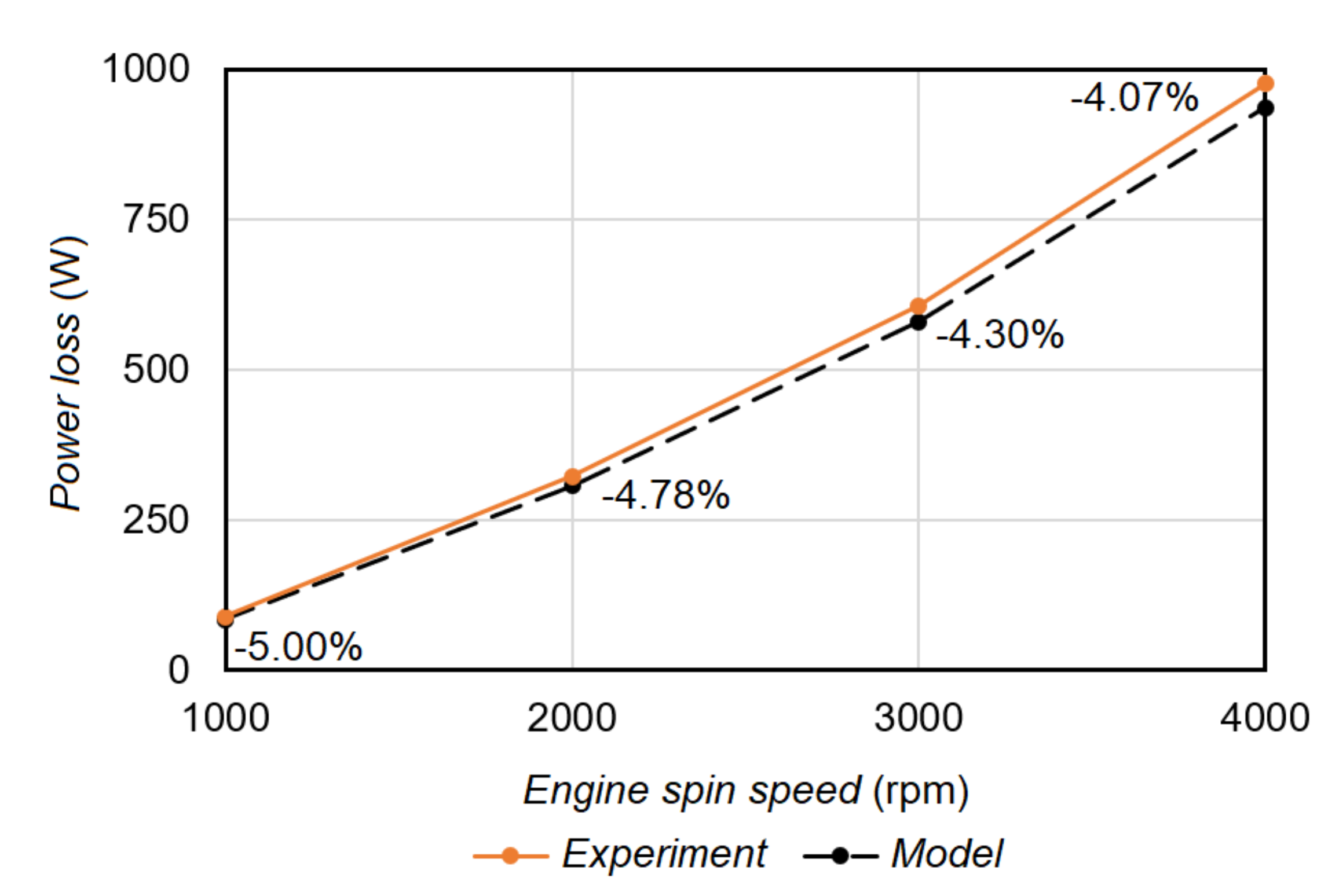
The net connecting rod big-end was converted to mean power loss to be compared with the results computed by the model. Figure 4 shows the experimental data versus the model results, together with the associated percentage relative error. A good agreement can be observed (maximum percentage relative error equal to 5%).

4. Results and Discussion

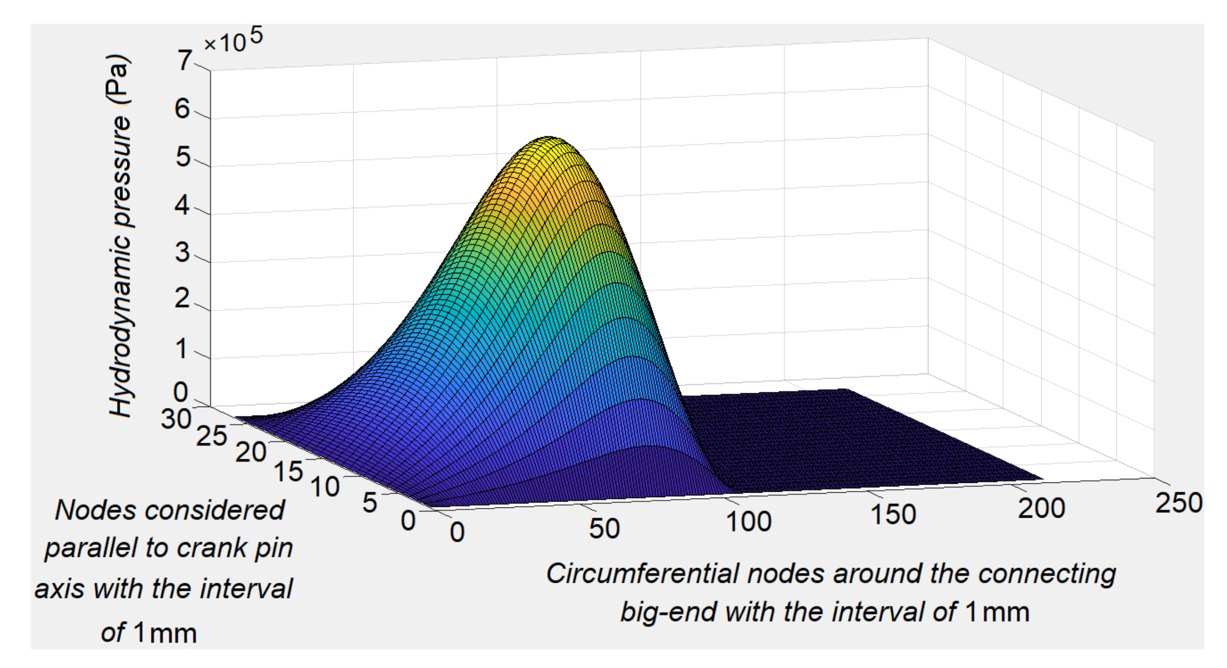
Generated hydrodynamic pressure at connecting rod big-end and crankpin is illustrated by Figure 5. Positive hydrodynamic pressure has been developed at half of the journal/bearing interface as it is treated as a π film bearing; the pressure at second half of the journal/bearing junction is considered equal to the saturation pressure (crankcase pressure assumed equal to the atmospheric pressure).
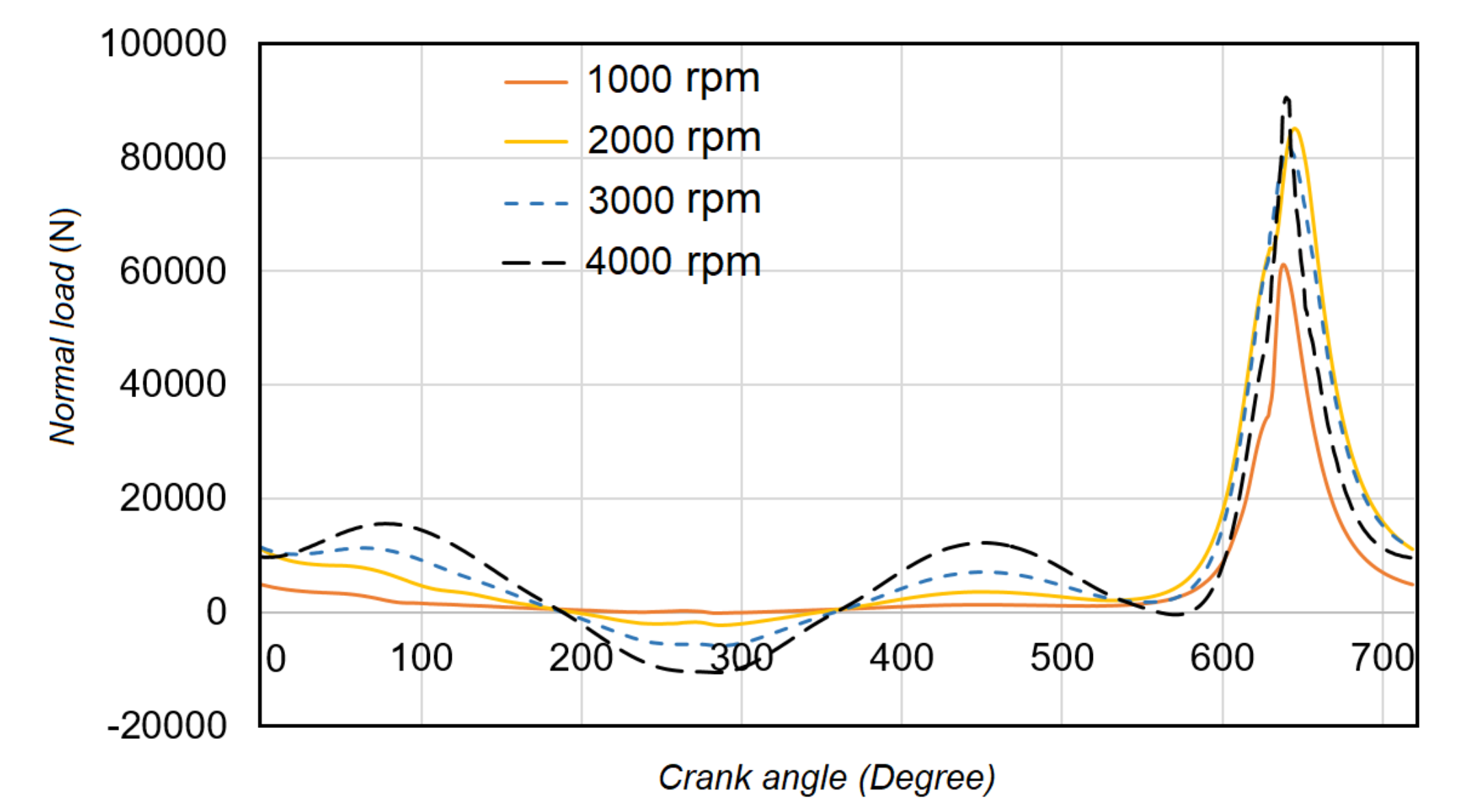
Figure 6 shows instantaneous net load, W, acting on the crankpin which is contributed by gas pressure and inertial imbalances due to reciprocating and rotating masses. During exhaust and intake strokes, inertial forces are major contributors as the gas pressure acting on the piston mostly equals to saturation pressure; in contrary, during compression and expansion strokes, gas pressure acting on the piston plays significant role in comparison to reciprocating and rotating inertial forces.
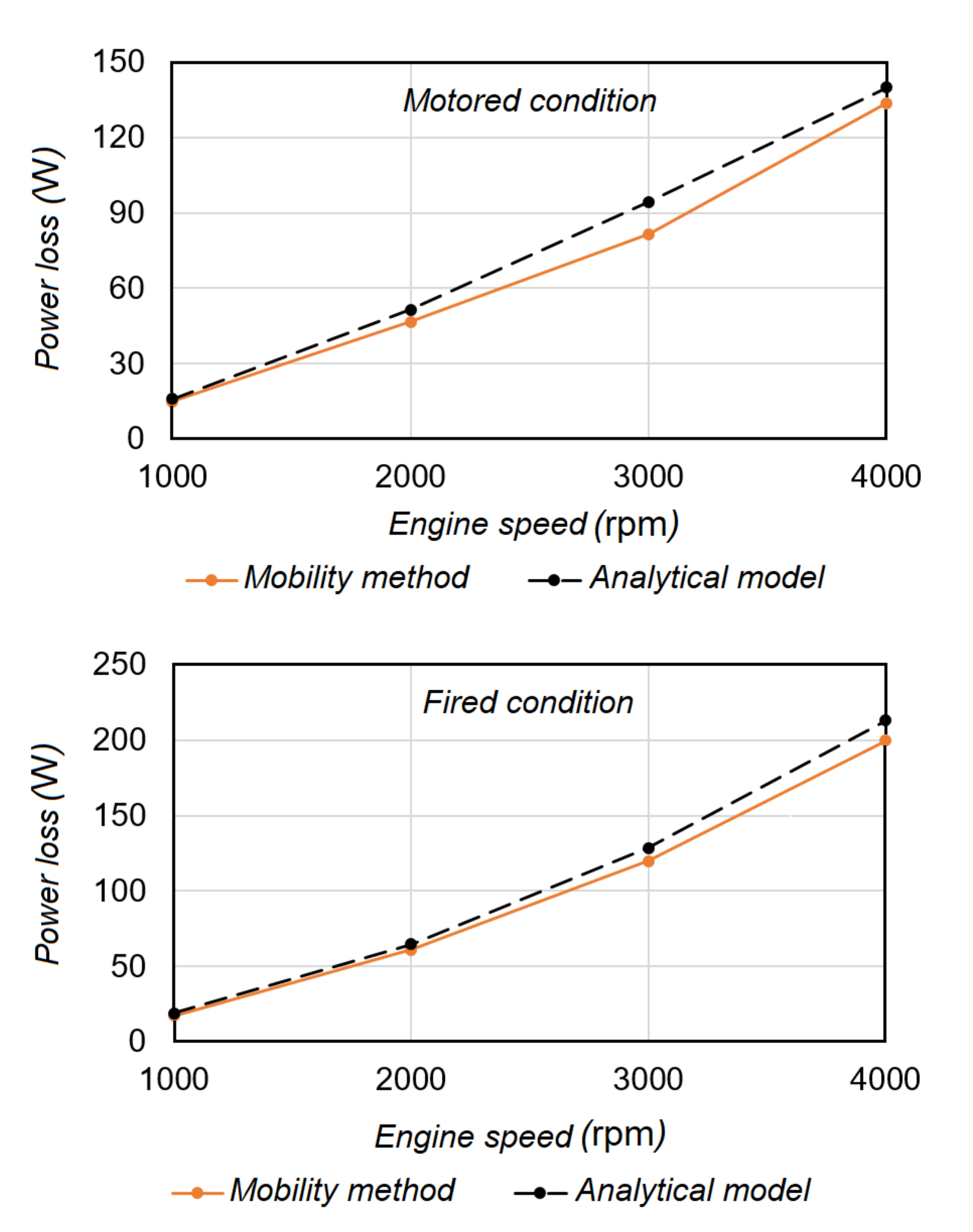
Increment in the relative surface velocities of the connecting rod big-end and crankpin journal increases the power loss caused by the increase in shear stress within the oil film at bearing surfaces junction. On the other hand, as hydrodynamic lubrication is considered at lubricated surfaces interface, friction loss is directly proportional to engine spin speed, oil viscosity and inlet oil temperature. Figure 7 demonstrates the effect of engine spin speed on power loss calculated by the model, at inlet lubricant temperature of 90 ° C ( η = 11.734 mPa·s), under fired and motored conditions. A comparative illustration is provided by Figure 8, where reasonable agreement can be found between power loss calculated by two approaches, with the benefit of reduced numerical effort by current model. The power loss under fired condition is higher in comparison to that obtained under motored condition as the gas pressure is dramatically high under fired condition.
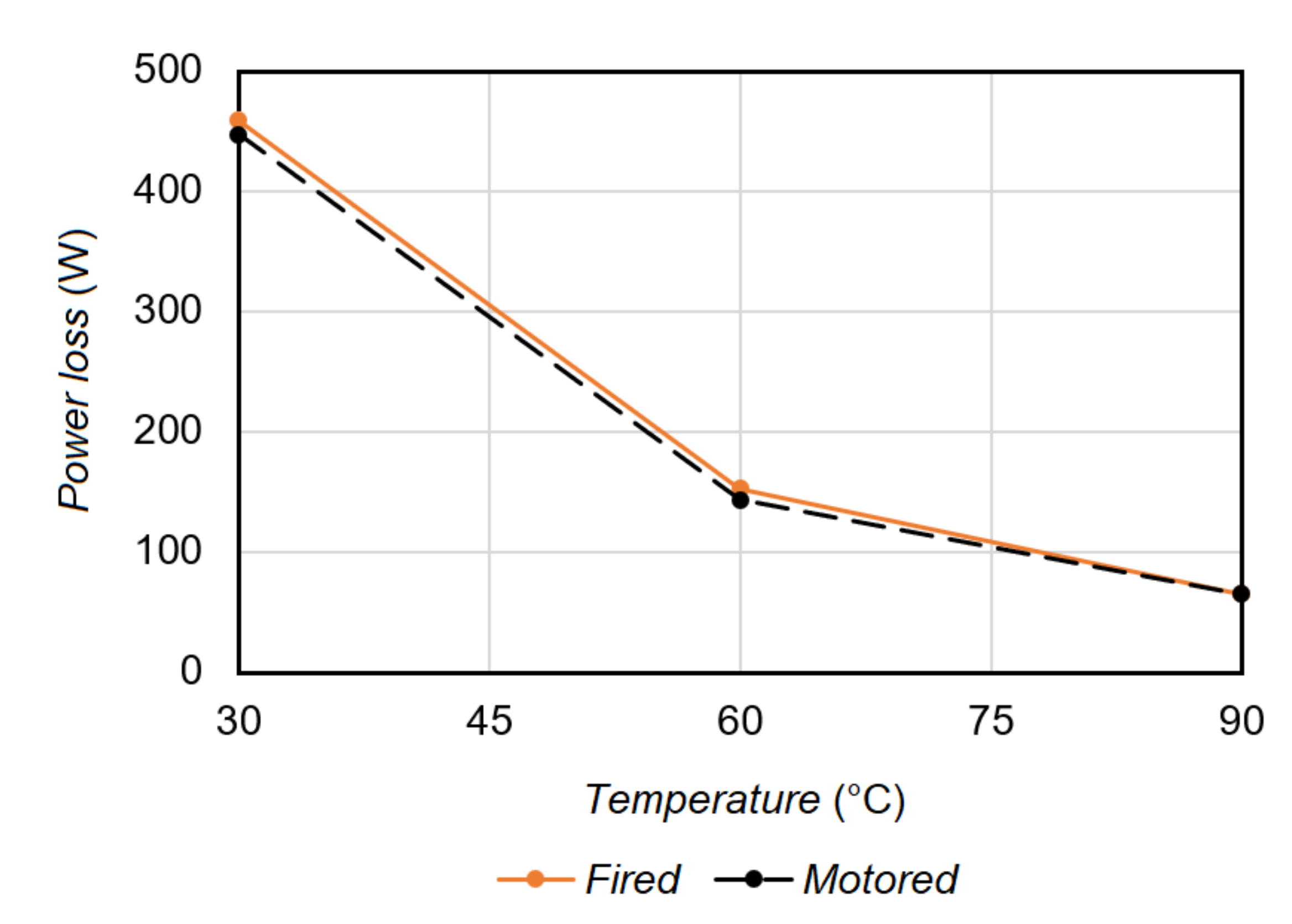
For a given oil, as the lubricant temperature increase, power loss reduces due to the reduction of oil viscosity and resistance against shear stress. Figure 9 illustrates the power loss dependence on lubricant temperature under fired and motored conditions at engine speed of 1000 rpm. Power loss calculated under both operating conditions significantly reduces as oil temperature increases. As the oil viscosity is reduced with temperature increment, fluid resistance against shear stress drops down, therefore power loss has been lessened. Highest resistance against shear stress occurs at 30 ° C (11.734 mPa), the steep slope of power loss from 30 ° C to 60 ° C is observed, while temperature exceeds the 60 ° C, the lubricant is changed and the rate of power loss is reduced. As the viscosity dependency on temperature is not linear and it can be varied and behaves with deviant manner at different ranges of temperature, it can be observed that the oil ( S A E 0 W   30 ) viscosity is more sensitive to the temperature range lower than 60 ° C.
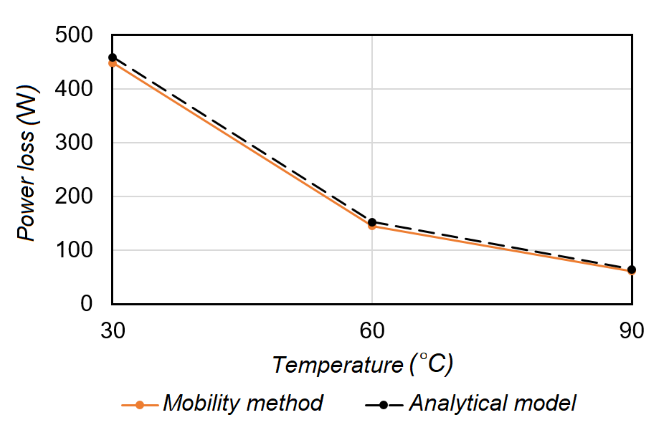
Figure 10 illustrates the same effect of temperature and behavior using proposed formulation and Mobility method to calculate the power loss. One of the main disadvantages of high operating temperature is to encourage mixed lubrication at bearing surfaces junction due to low effective oil viscosity and reduction of lubricant load carrying capacity.
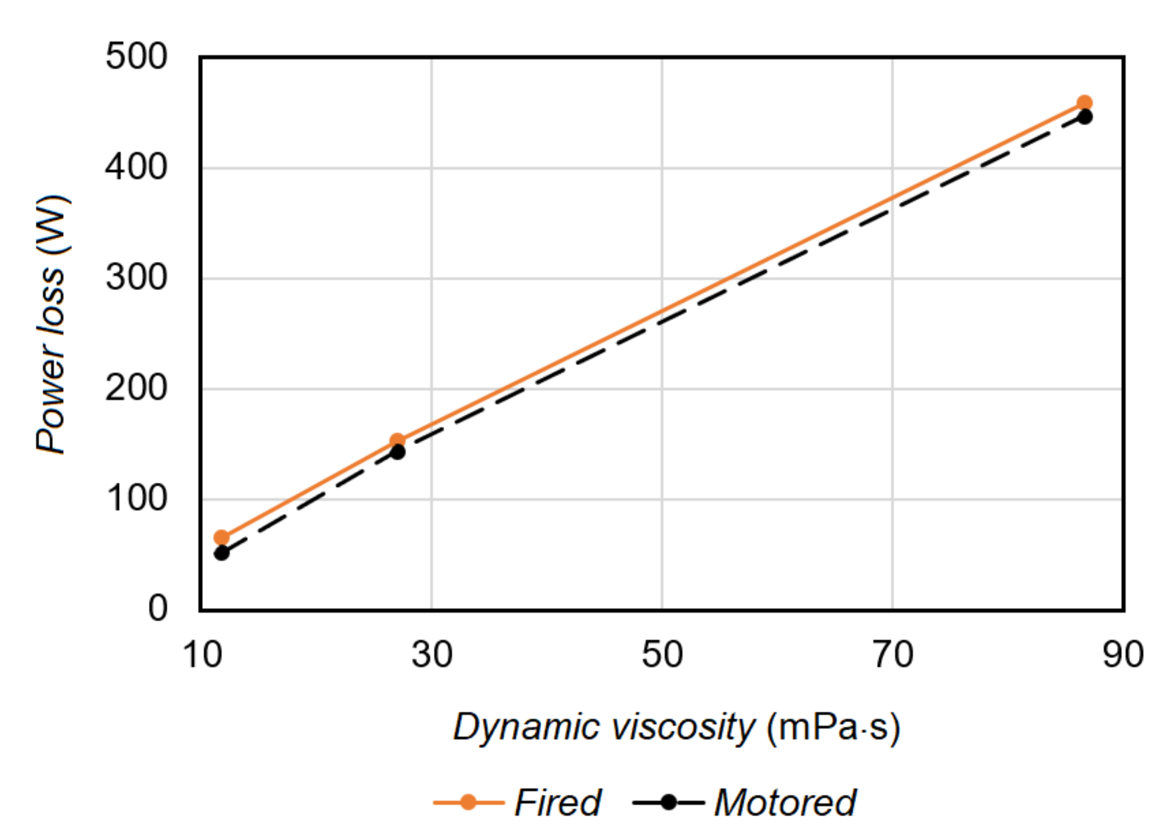
Also the effect of different lubricant viscosities (11.734, 27.008 and 86.600 mPa·s) has been examined and the results are shown by Figure 11. It is proved that as oil viscosity increases, its resistance against shear stress is improved and consequently higher power loss is obtained.

5. Conclusions

The purpose of the current study is to develop a hydrodynamic lubrication model to evaluate tribological performance of connecting rod big-end bearing. Instantaneous eccentricity between journal and bearing has been calculated through the force equilibrium acting on the journal using Newton–Raphson’s scheme. Finite difference method is applied to calculate hydrodynamic pressure at connecting rod big-end and crankpin interface as well as frictional power loss. Besides, well known Mobility method has been applied to be compared against the analytical model; good agreement has been observed between the two approaches. In addition the proposed model was validated by experimental data, which encourages reduction of huge numerical efforts associated with Mobility method. The effects of engine spin speed, operating condition, lubricant viscosity and oil temperature on connecting rod big-end bearing lubrication are investigated. Current study can be employed as a practical tool for companies’ engineers and researchers to have a reliable estimation of power loss at connecting rod big-end and crank pin at early stages of design with lower computational time costs. It can be used along piston ring assembly lubrication model to have an overall sense of design parameters and their effects on engine tribological performance. Other important and influential parameters such as definition of temperature field and sliding surface deformation must be involved to have more accurate and realistic evaluation of connecting rod big-end lubrication and tribology.

Author Contributions

A.R. and C.D. developed and verify the formulation, A.R. and P.B. implement the MATLAB® codes and perform experimental trials, and C.D. supervised and finalized the research to be submitted.

Funding

This research received no external funding.

Acknowledgments

The authors wish to gratefully thank DEPEC group.

Conflicts of Interest

The authors declare no conflict of interest.

Appendix A. Hydrodynamic Force Components, Fr and Ft Based on Mobility Method for π Film Lubricated Journal Bearing

According to Figure 3, hydrodynamic force components acting on the journal, F h , is the resultant force of radial force, F r and tangential force, F t can be calculated using following equations:
F r = 0 π L x 2 L x 2 p ( x , α ) R cos α d x d α
F t = 0 π L x 2 L x 2 p ( x , α ) R sin α d x d α
where
p ( α ) = 6 η 1 c 2 ϵ ω ¯ sin α ( 1 + ϵ cos α ) 3 ( x 2 L x 2 4 )
Substituting (A3) in (A1) gives:
F r = R η ω ¯ L x 3 c 3 e 0 π sin ( α ) cos ( α ) ( 1 + ϵ cos ( α ) ) 3 d α
Regarding the solution presented by Booker [21], Equation (A4) can be written as:
F r = R η ω ¯ L x 3 c 3 e I 3 11 ( π ) I 3 11 ( 0 )
where
I 3 11 ( α ) = 1 ϵ I 3 10 ( α ) + I 2 10 ( α )
and
I 3 10 ( α ) = 1 2 ϵ ( 1 + ϵ cos ( α ) ) 2
I 2 10 ( α ) = 1 ϵ ( 1 + ϵ cos ( α ) )
Substituting (A3) in (A2) gives:
F t = R η ω ¯ L x 3 c 3 e 0 π sin 2 ( α ) ( 1 + ϵ cos ( α ) ) 3 d α
Applying Booker table of integrals [6] yields:
F t = R η ω ¯ L x 3 c 3 e I 3 20 ( π ) I 3 20 ( 0 )
where
I 3 20 ( α ) = 1 ϵ 2 ( 1 ϵ 2 ) I 3 00 ( α ) + 2 I 2 00 ( α ) I 1 00 ( α )
and
I 3 00 ( α ) = 1 2 ( 1 ϵ 2 ) ϵ sin ( α ) ( 1 + ϵ cos ( α ) ) 2 + 6 I 2 00 I 1 00
I 2 00 ( α ) = 1 ( 1 ϵ 2 ) ϵ sin ( α ) ( 1 + ϵ cos ( α ) ) + I 1 00
I 1 00 ( α ) = 1 ( 1 ϵ 2 ) cos 1 ϵ + cos ( α ) 1 + ϵ cos ( α )

References

  1. Rahnejat, H. (Ed.) Tribology and Dynamics of Engine and Powertrain: Fundamentals, Applications and Future Trends; Woodhead Publishing: Cambridge, UK, 2010. [Google Scholar]
  2. Stachowiak, G.; Batchelor, A.W. Engineering Tribology; Butterworth-Heinemann: Oxford, UK, 2013. [Google Scholar]
  3. Khonsari, M.M.; Booser, E.R. Applied Tribology: Bearing Design and Lubrication; John Wiley and Sons: New York, NY, USA, 2017. [Google Scholar]
  4. Delprete, C.; Razavykia, A. Piston dynamics, lubrication and tribological performance evaluation: A review. J. Eng. Res. 2018. [Google Scholar] [CrossRef]
  5. Delprete, C.; Razavykia, A. Piston ring–liner lubrication and tribological performance evaluation: A review. J. Eng. Tribol. 2018, 232, 193–209. [Google Scholar] [CrossRef]
  6. Booker, J.F. Dynamically loaded journal bearings: Mobility method of solution. J. Basic Eng. 1965, 87, 537–546. [Google Scholar] [CrossRef]
  7. Booker, J.F. Dynamically-loaded journal bearings: Numerical application of the mobility method. J. Lubr. Technol. 1971, 93, 168–174. [Google Scholar] [CrossRef]
  8. Goenka, P.K. Analytical curve fits for solution parameters of dynamically loaded journal bearings. J. Tribol. 1984, 106, 421–427. [Google Scholar] [CrossRef]
  9. Fantino, B.; Godet, M.; Frêne, J. Dynamic Behaviour of an Elastic Connecting—Rod Bearing—Theoretical Study; SAE Technical Paper; SAE International: Warrendale, PA, USA, 1983; Volume 830307. [Google Scholar]
  10. Fantino, B.; Frene, J. Comparison of dynamic behavior of elastic connecting-rod bearing in both petrol and diesel engines. J. Tribol. 1985, 107, 87–91. [Google Scholar] [CrossRef]
  11. Hirani, H.; Athre, K.; Biswas, S. Dynamically loaded finite length journal bearings: Analytical method of solution. J. Tribol. 1999, 121, 844–852. [Google Scholar] [CrossRef]
  12. Paranjpe, R.S. Analysis of non-Newtonian effects in dynamically loaded finite journal bearings including mass conserving cavitation. J. Tribol. 1992, 114, 736–744. [Google Scholar] [CrossRef]
  13. Livanos, G.; Kyrtatos, N.P. A Model of the Friction Losses in Diesel Engines; SAE Technical Paper; 2006-01-0888; SAE International: Warrendale, PA, USA, 2006. [Google Scholar]
  14. DuBois, G.B.; Ocvirk, F.W. Analytical Derivation and Experimental Evaluation of Short-bearing Approximation for Full Journal Bearing; NACA Report; NACA: Boston, MA, USA, 1953; Volume 1157. [Google Scholar]
  15. Vignolo, G.G.; Barilá, D.O.; Quinzani, L.M. Approximate analytical solution to Reynolds equation for finite length journal bearings. Tribol. Int. 2011, 44, 1089–1099. [Google Scholar] [CrossRef]
  16. Chasalevris, A.; Sfyris, D. Evaluation of the finite journal bearing characteristics, using the exact analytical solution of the Reynolds equation. Tribol. Int. 2013, 57, 216–234. [Google Scholar] [CrossRef]
  17. Abbasi, A.; Khadem, S.E.; Bab, S.; Friswell, M.I. Vibration control of a rotor supported by journal bearings and an asymmetric high-static low-dynamic stiffness suspension. Nonlinear Dyn. 2016, 85, 525–545. [Google Scholar] [CrossRef]
  18. Dousti, S.; Allaire, P.; Dimond, T.; Cao, J. An extended Reynold equation applicable to high reduced Reynolds number operation of journal bearings. Tribol. Int. 2016, 102, 182–197. [Google Scholar] [CrossRef]
  19. Booker, J.F. Basic equations for fluid films with variable properties. J. Tribol. 1989, 111, 475–479. [Google Scholar] [CrossRef]
  20. Martin, F.A. Friction in Internal Combustion Engine Bearings. Proc. Inst. Mech. Eng. 1985, C67/85, 1–17. [Google Scholar]
  21. Booker, J.F. A Table of the Journal-Bearing Integral. J. Basic Eng. 1965, 87, 533–535. [Google Scholar] [CrossRef]
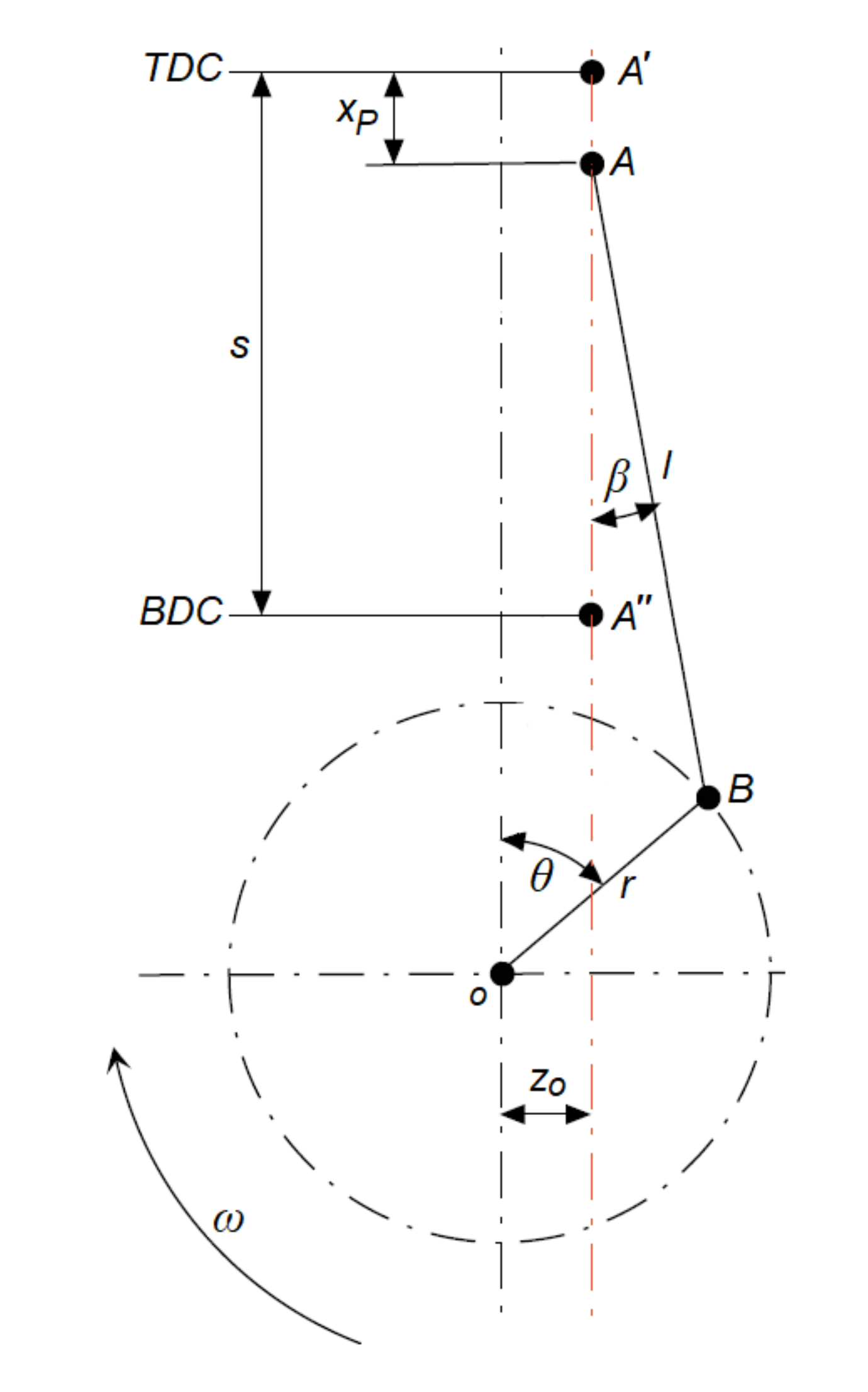
Figure 1. Schematic representation of crank mechanism with offset layout.
Lubricants 07 00047 g001
Figure 2. Finite difference mesh developed over the journal.
Lubricants 07 00047 g002
Figure 3. Schematic representation of journal and bearing.
Lubricants 07 00047 g003
Figure 4. Model validation.
Lubricants 07 00047 g004
Figure 5. Hydrodynamic pressure at crankpin journal/connecting rod big-end interface (engine spin speed ω = 2000 rpm).
Lubricants 07 00047 g005
Figure 6. Instantaneous net load, W, contributed by the gas pressure and reciprocating masses.
Lubricants 07 00047 g006
Figure 7. Effect of engine spin speed on power loss under fired and motored conditions.
Lubricants 07 00047 g007
Figure 8. Power loss at connecting rod big-end calculated by proposed model and Mobility method under motored and fired conditions.
Lubricants 07 00047 g008
Figure 9. Effect of temperature on power loss under fired and motored conditions.
Lubricants 07 00047 g009
Figure 10. Effect of temperature on power loss under fired condition, calculated by Mobility method and model.
Lubricants 07 00047 g010
Figure 11. Effect of oil viscosity on power loss under fired and motored conditions.
Lubricants 07 00047 g011
Table 1. Relevant data for engine, connecting rod big-end and crankpin journal.
cjournal-bearing clearance (mm)0.026
Dcylinder bore (mm)83.80
lconnecting rod length (mm)153
L x journal width (mm)19.5
rcrank radius (mm)49.5
R j crankpin radius (mm)25.45
m p i s piston mass (kg)0.540
m p i n wrist pin mass (kg)0.257
m c r connecting rod mass (kg)0.714
z o w p wrist pin offset (mm)0.5
z o c crankshaft offset (mm)0
η oil dynamic viscosity (mPa·s)11.734
σ combined surface roughness ( μ m)0.37