Abstract
Fluid friction in elastohydrodynamically lubricated (EHL) contacts depends strongly on the lubricant considered. Synthetic oils can have significantly lower fluid friction than mineral oils. Water-containing fluids have the potential to significantly reduce fluid friction further. The aim of this study is to investigate the film formation and frictional behavior of highly-loaded EHL contacts with water-containing fluids. Comparisons are made with mineral and polyalphaolefin oils. Measurements at an optical EHL tribometer show good lubricant film formation of the considered water-containing gear fluids. Measurements at a twin-disk test rig show coefficients of friction smaller than 0.01, which is referred to as superlubricity, for all considered operating conditions.
1. Introduction
Fluid friction in elastohydrodynamically lubricated (EHL) contacts, e.g., in gears and bearings, is determined by inner friction due to molecular interactions of molecules. Characteristic flow behavior of gear fluids is non-Newtonian with decreasing viscosity with increasing shear rate. Friction curves are typically represented by the coefficient of friction over slip ratio (e.g., Mayer [1], Bobach et al. [2], Bader et al. [3], Evans et al. [4], Björling et al. [5]). The pressurized contact area of highly-loaded EHL contacts with more than 1000 N/mm2 results in a complex lubricant behavior and different friction regimes over the slip ratio (Ndiaye et al. [6], Bair et al. [7], Martinie et al. [8], Bair [9], Bair et al. [10]). For very low slip ratios, a linear (Newtonian) regime is observed. This is followed by a non-linear (shear thinning) regime with the coefficient of friction increasing digressively until, commonly, a maximum of the coefficient of friction is reached. This plateau is generally referred to as limiting shear stress. Its physical origin is discussed in terms of shear banding, wall slip, glassy state transitions, and shear localization (Martinie et al. [8]). For even higher slip ratios, the coefficient of friction is governed by the thermal regime and is reduced due to increasing frictional heat and contact temperatures.
Mayer [1] measured friction curves of highly-loaded EHL contacts at a twin-disk test rig under various operating conditions and with various base oils. For fluid film lubrication, the measured coefficient of friction was between 0.020 ≤ µ ≤ 0.060 for a mineral oil, between 0.010 ≤ µ ≤ 0.040 for a polyalphaolefin oil, between 0.010 ≤ µ ≤ 0.035 for a polyalkylene glycol oil and between 0.008 ≤ µ ≤ 0.020 for a polyether oil. Even though the base oil’s molecular structure and relating properties, e.g., viscosity index, pressure–viscosity coefficient, and density, are different, the friction curves exhibit the typical characteristic regimes described above. Sagraloff et al. [11] used the same twin-disk test rig to measure friction curves of highly-loaded EHL contacts with a water-based fluid in a fluid film lubrication regime. The water-based fluid is referred to a liquid solution of water as base fluid and polymers. Results show very low coefficients of friction of below 0.01. The low friction is expected to be related to the low pressure–viscosity coefficient of the water-based fluid, resulting in low contact viscosity and shear stress. Martin et al. [12] state a low capability of water to form lubricant films at high pressures.
The frictional behavior of water-containing fluids was analyzed in several studies. A water-containing fluid is referred to as a water-soluble base oil with significant water content. Chen et al. [13] performed experimental investigations on highly-loaded EHL contacts at a ball-on-disk tribometer with a water-soluble glycerol as base oil with water content. Ultra-low coefficients of friction between 0.005 ≤ µ ≤ 0.010 were measured at quasi-stationary operating conditions after run-in. They propose the following lubrication mechanism to explain the remarkable friction reduction: In ambient conditions, a microscopic layer of FeOOH is formed on the steel surfaces. Based on that, layers of hydrogen bonded networks of base oil molecules are adsorbed to the surfaces via hydrogen bonds. Between these layers, a thin layer of mainly water molecules allows easy sliding, which results in ultra-low friction. Li et al. [14,15] conducted further investigations at a ball-on-disk tribometer and measured ultra-low coefficients of friction of 0.004 ≤ µ ≤ 0.006 for highly-loaded EHL contacts using polyhydroxy alcohol or glycerol as base oil with water and acid content. The very low friction is explained by a lubrication model similar to the one by Chen et al. [13]. They also show increasing lubricant film thickness with increasing base oil content. Wang et al. [16] performed friction measurements with water-containing fluids at a ball-on-disk tribometer. Polyalkylene glycol was used as water-soluble base oil. The water content was varied between 10% and 90% and showed a significant influence on the coefficient of friction and operational stability. Ultra-low friction of µ < 0.01 was achieved for water contents of up to 60%. For water contents below 30%, stable operating conditions were only observed at a long running time. A water content between 30% and 60% was recommended to achieve ultra-low and stable operating conditions. The proposed lubrication mechanism is similar to the ones suggested by Chen et al. [13].
The literature indicates a large potential of water-containing fluids to achieve ultra-low friction in highly-loaded EHL contacts, while at the same time providing good EHL film formation. The aim of this study is to evaluate the EHL film formation of water-containing gear fluids at an optical EHL tribometer and friction at a twin-disk test rig. The results of this study were partly presented at a technical session at the 7th European Conference in Tribology in Vienna in 2019 (Yilmaz et al. [17]).
2. Lubricants
Within this study, three water-containing fluid designs for gearbox applications were compared with conventional gear oils. Table 1 shows the corresponding kinematic viscosities and densities. The mineral oil MIN-10 is specified by Laukotka [18] and used as a link to the results of Mayer [1]. The polyalphaolefin oils PAO-09 and PAO-05 have the same base oil with typical gear oil additives incorporated. Its nominal kinematic viscosities of 9.0 and 5.0 mm2/s are specified at 100 °C. The water-containing fluids PAGW-09, PAGW-05A, and PAGW-05B are based on water-soluble polyalkylene glycols with water content of up to 70%. Note that the given kinematic viscosities at 100 °C are approximated. PAGW-09 and PAGW-05A have the same additives incorporated but different kinematic viscosities. PAGW-05B has the same kinematic viscosity as PAGW-05A but different additives incorporated. The densities of the water-containing gear fluids are approximately 30% higher than for the conventional gear oils.

Table 1.
Properties of the investigated lubricants.
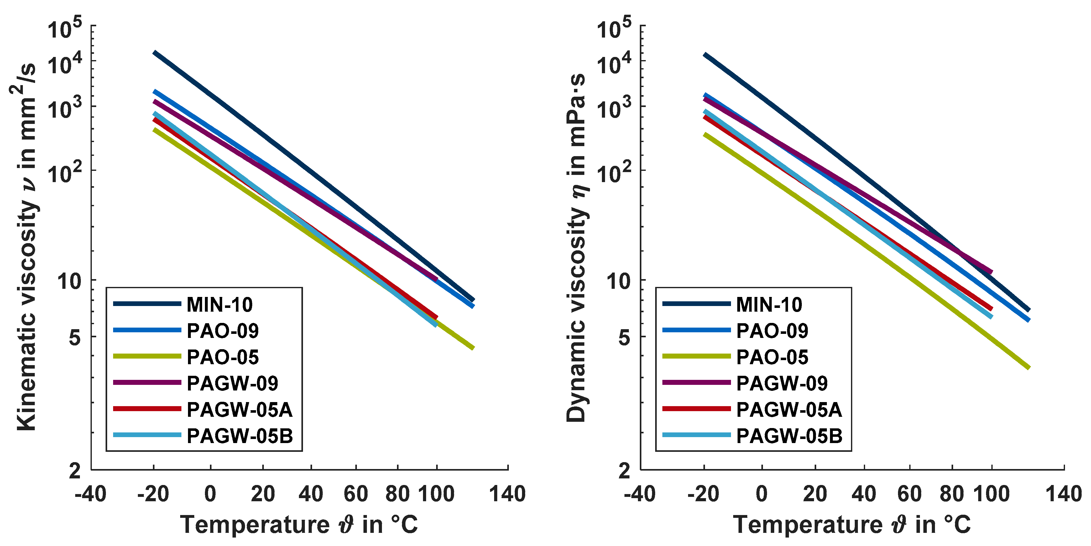
Figure 1 illustrates the kinematic and dynamic viscosity over temperature according to DIN 51563 [19]. The different viscosity levels and indices can be recognized. As the dynamic viscosity includes the influence of the lubricant density, the higher density of the water-containing gear fluids comes into effect.
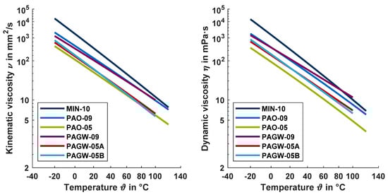
Figure 1.
Viscosity–temperature behavior of the lubricants investigated, according to DIN 51563.
3. Experimental Setups
This section describes the experimental setups of the optical EHL tribometer and twin-disk test rig considered, as well as the test parts and operating conditions.
3.1. Optical EHL Tribometer
The EHL film thickness of the lubricants considered was observed and evaluated using an optical EHL tribometer based on thin film colorimetric interferometry.
3.1.1. Description and Measurement Technique
The optical EHL tribometer at FZG is from the Brno University of Technology (BUT) and identical in construction to the one considered by Omasta et al. [20] and Ebner et al. [21]. The following short description of the test rig is mainly based on these works and formulations.
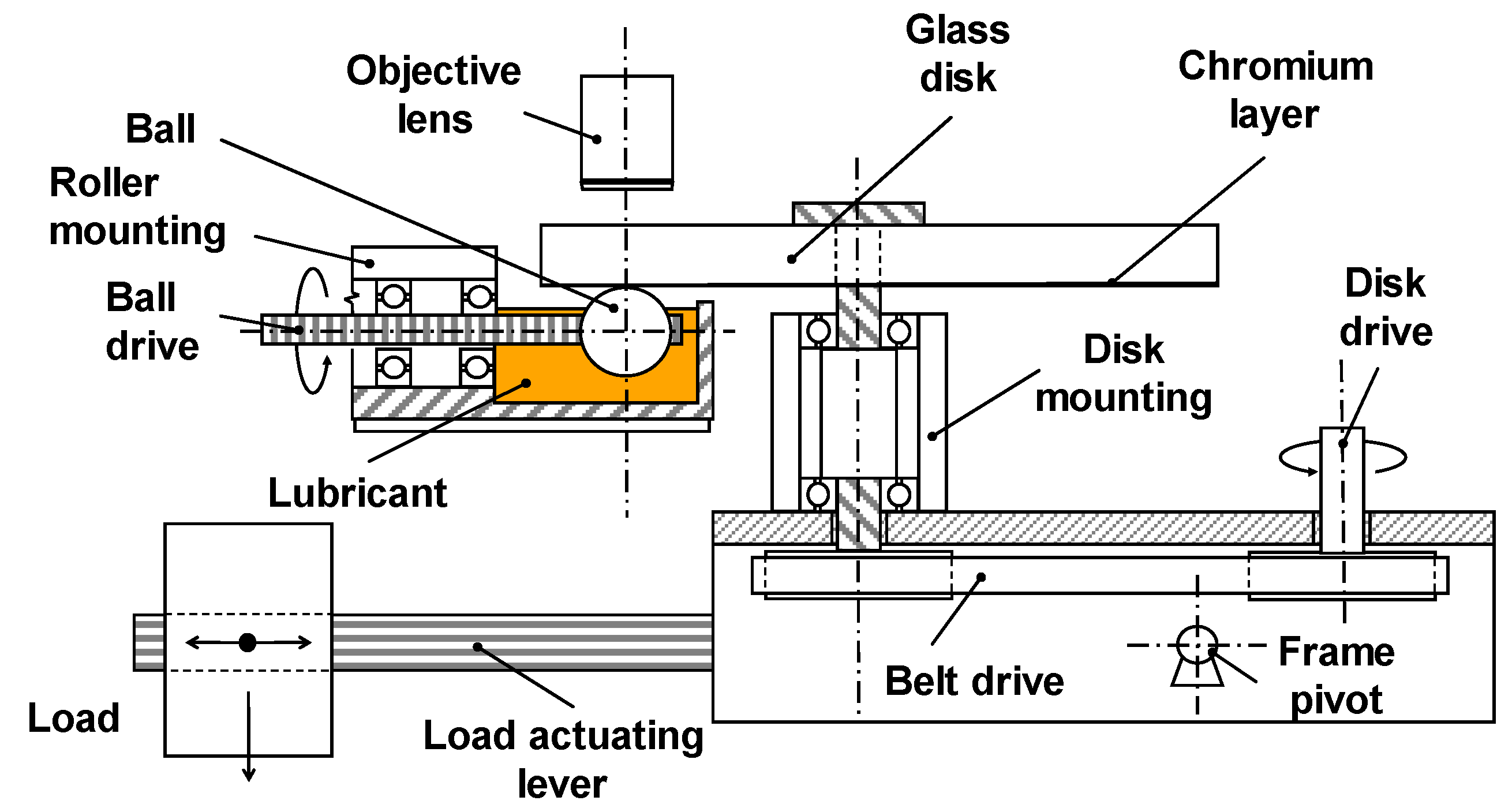
Figure 2 shows the mechanical layout of the optical EHL tribometer. In this ball-on-disk tribometer, a transparent disk made from BK7 glass is loaded using a dead-weight lever mechanism against a polished steel ball. The disk, as well as the ball, is driven separately by two speed-controlled electric motors, which allows continuous variation of the surface velocities. The sum of the surface velocities v1 and v2 is defined as sum velocity vΣ, whereas the difference between the surface velocities v1 and v2 is the sliding velocity vg:
vΣ = v1 + v2
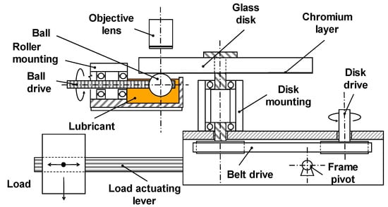
Figure 2.
Mechanical layout of the optical elastohydrodynamically lubricated (EHL) tribometer similar to Omasta et al. [20].
vg = v1 − v2 with v1 > v2
The slip ratio s is defined as:
The glass disk was coated with a thin chromium layer on the contact side with the polished steel ball, which allows an optical interference to occur. The contact was observed through an industrial microscope and was illuminated episodically with a high-intensity xenon continuous lamp. The resulting chromatic interferograms were recorded using a high-speed CMOS camera. The lubricant film thickness was evaluated based on the thin film colorimetric interferometry (Hartl et al. [22], Molimard et al. [23]). An optical interference occurs when two light beams reflected from nearby interfaces are composed together. In the case of the optical EHL tribometer, the first interface was between the thin chromium layer of the glass disk and the lubricant, and the second interface was between the ball and the lubricant. The resulting chromatic interferograms were converted to a quantitative lubricant film thickness using a color-matching algorithm and CIELAB color-film thickness calibration integrated in the AChILES software.
3.1.2. Operating Conditions
Table 2 shows the operating conditions considered at the EHL tribometer. Overall, 14 sum velocities v∑ from 1.6 to 4.0 m/s were investigated, and a color interferogram was recorded for each for pure rolling (slip ratio of s = 0%). The applied normal load of FN = 30 N corresponds to a Hertzian pressure of pH = 530 N/mm2. The experiments were conducted under dip lubrication with an oil temperature of ϑOil = 40 °C.
Table 2.
Operating conditions at the EHL tribometer.
3.2. Twin-Disk Test Rig
Twin-disk test rigs are often used for basic investigations on rolling-sliding contacts of gears. Good transferability of friction behavior is known.
3.2.1. Mechanical Setup
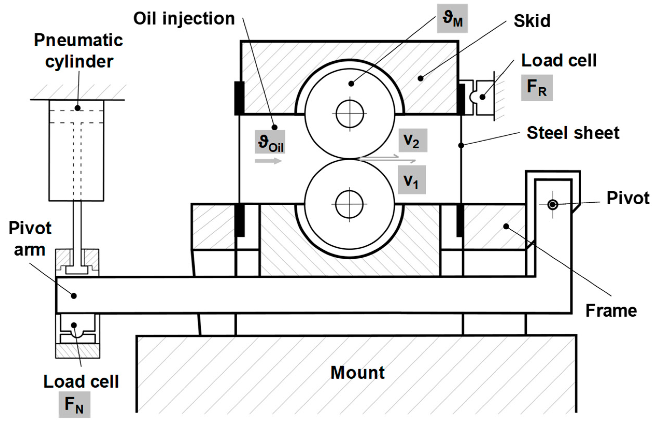
Figure 3 shows the mechanical layout of the considered FZG twin-disk test rig, which was designed by Stößel [24]. The following description of the test rig is based mainly on the works and formulations of Lohner et al. [25] and Ebner et al. [26].
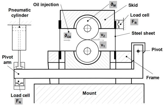
Figure 3.
Mechanical layout of the FZG twin-disk test rig considered, according to Yilmaz et al. [27].
Both test disks were press-fitted onto shafts, which can be independently driven by two three-phase motors. Traction drives mounted between the motors and driving shafts allow continuous variation of speed. The normal force FN in the disk contact was applied by a pneumatic cylinder via the pivot arm where the lower disk was mounted. The upper disk was mounted in a skid, which was attached to the frame by thin steel sheets. The skid was supported laterally by a load cell so that the friction force FR in the disk contact for sliding velocities vg ≠ 0 m/s can be measured as reaction force with hardly any displacement of the skid. An injection lubrication unit with heating and cooling possibilities and a filter system provides lubricant at the desired oil inlet temperature ϑOil to be injected directly into the inlet region of the disk contact. Normal force FN, friction force FR, oil inlet temperature ϑOil, surface velocities v1 and v2, and bulk temperature of the upper disk ϑM were measured. ϑM is recorded by a Pt100 resistance temperature sensor 5 mm below the surface of the disk. The definitions of the sum velocity v∑, sliding velocity vg, and slip s are in accordance with the EHL tribometer (Equations (2)–(4)). The coefficient of friction can be calculated as follows:
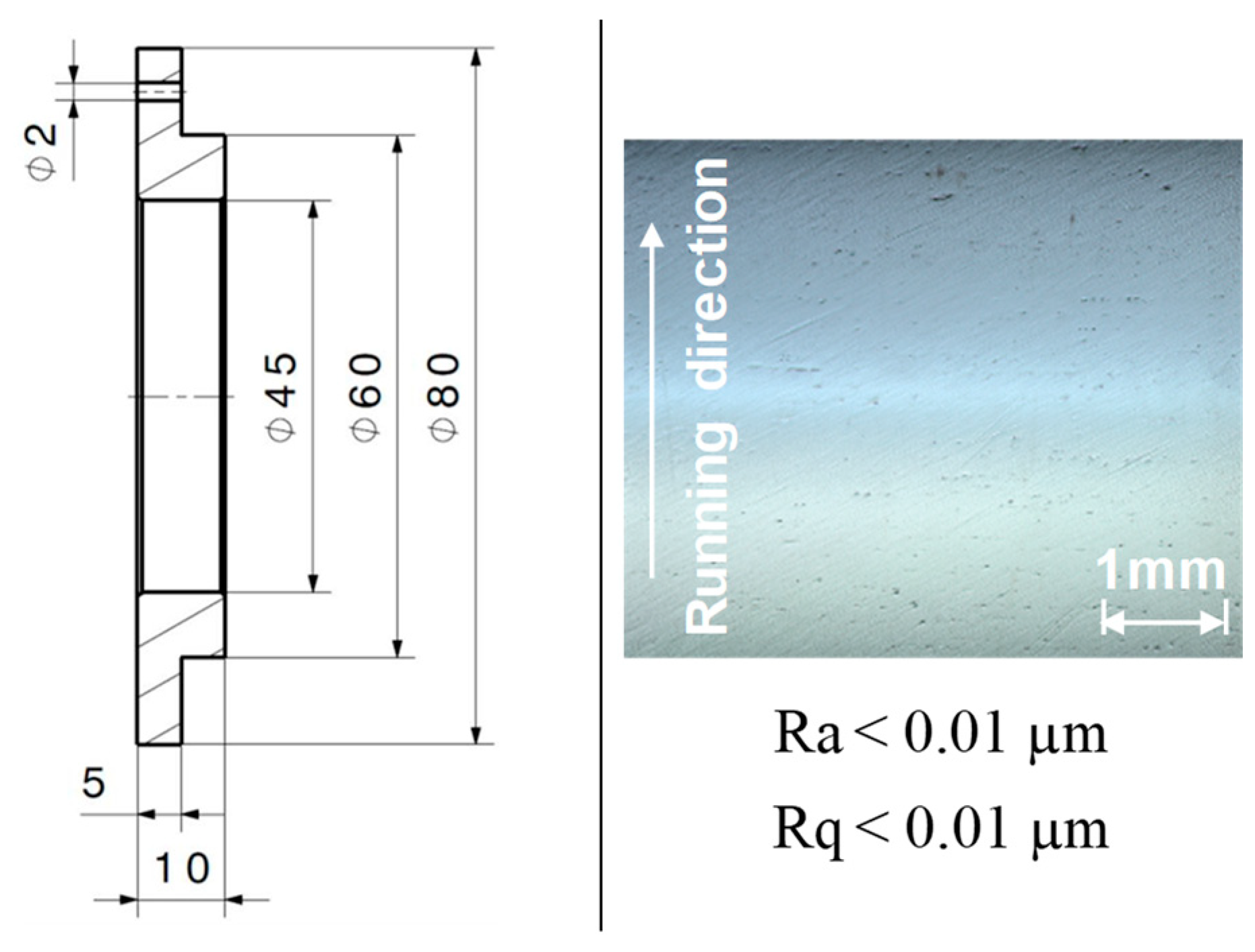
All experiments were conducted under line contact conditions with cylindrical disks having a diameter of 80 mm and a width of 5 mm, as shown in Figure 4, left. To ensure an evenly distributed load over the disk width of 5 mm, a contact print on aluminum foil was evaluated before each test. Any misalignment was carefully corrected mechanically.
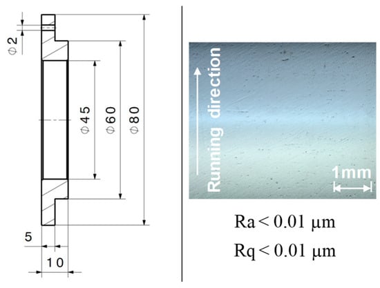
Figure 4.
Test disk geometry (left) and light microscope picture of the polished surface before test run (right).
The disks were made of case-carburized steel 16MnCr5 (AISI 5115) with a surface hardness of 690–740 HV1 and case-hardening depth of CHD550HV1 = 0.9 + 0.2 mm. All disk surfaces were peripherally ground and mechanically polished to an arithmetic mean roughness of Ra < 0.01 µm, as shown in Figure 4, right. The profile method was used to measure the surface roughness across the disk width direction with a measurement length of Lt = 4 mm and a cut-off wavelength of λc = 0.08 mm.
3.2.2. Operating Conditions
Table 3 shows the operating conditions considered at the twin-disk test rig. Each friction curve was recorded for slip ratios s from 0% to 50% at constant load and sum velocity. Thereby, the surface velocities were adjusted to s = 0% before the disks were brought into contact. After applying load, the slip ratio was increased incrementally. The coefficients of friction and bulk temperatures were recorded as quasi-stationary values, i.e., when the change in bulk temperature ΔϑM/Δt was smaller than 0.5 K/min. Five sum velocities of vΣ = {1; 2; 4; 8; 16} m/s were investigated for loads of FN = {980; 3920} N, which corresponds to Hertzian pressures of pH = {600; 1200} N/mm2.
Table 3.
Operating conditions at the twin-disk test rig.
The experiments were conducted under injection lubrication, whereby the lubricant was injected with a flow rate of 1.6 l/min to the disk contact inlet with an oil injection temperature ϑOil = 60 °C.
Friction curves were aborted when the measured disk bulk temperature ϑM exceeded 160 °C, due to initiated annealing effects in AISI 5115. A new pair of mechanically polished disks was used for each lubricant. Each new pair of disks was run-in with the investigated lubricant for 30 min at ϑOil = 60 °C, pH = 1200 N/mm2 (FN = 3920 N), vΣ = 1 m/s, and s = 20%.
4. Results and Discussion
In this section, the experimental results from the optical EHL tribometer and twin-disk test rig are presented and discussed.
4.1. Optical EHL Tribometer
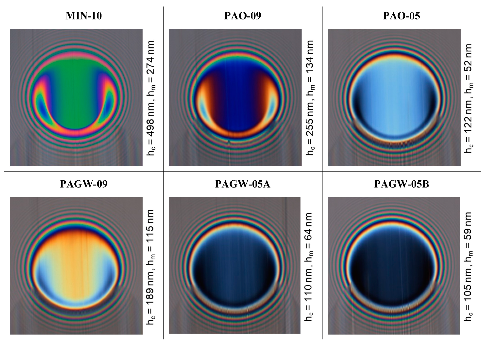
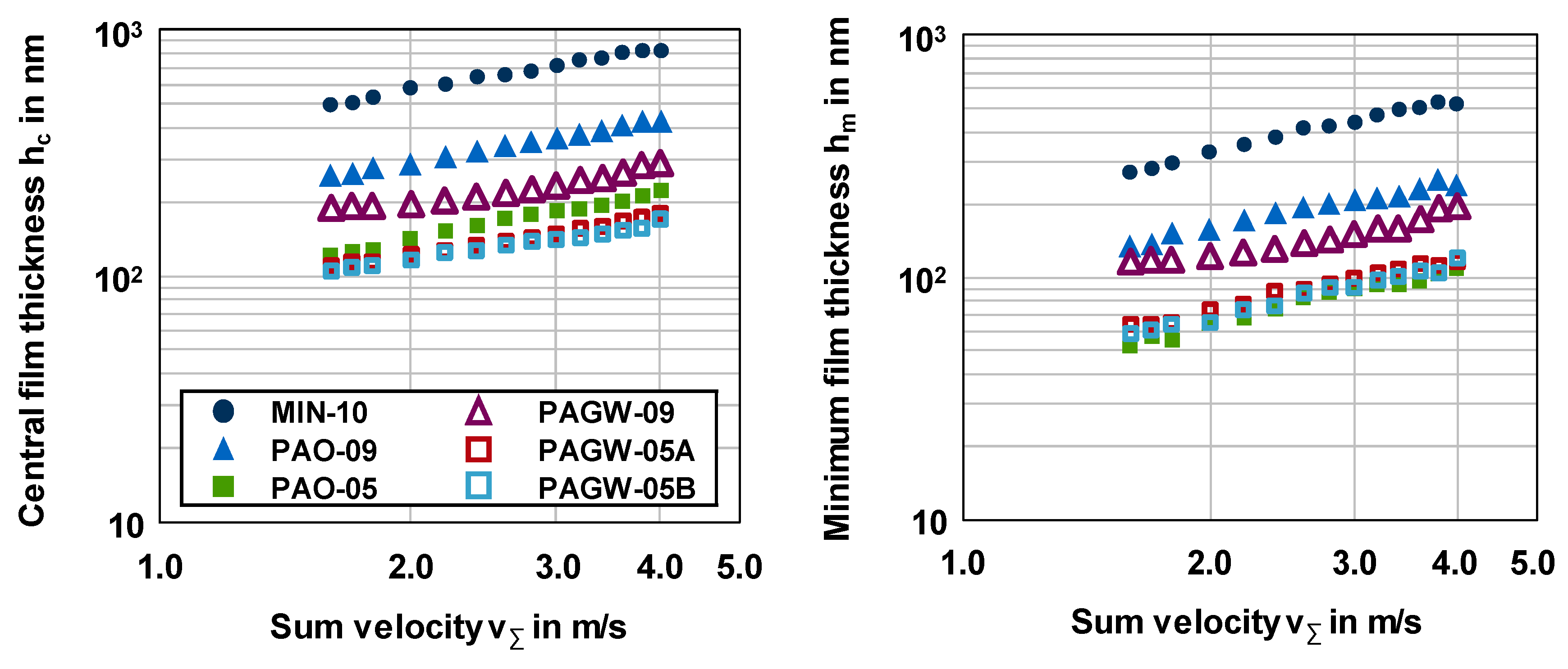
Figure 5 shows measured interferograms for an oil temperature of ϑOil = 40 °C, a Hertzian pressure of pH = 530 N/mm2, and a slip ratio of s = 0% for all considered lubricants with an example sum velocity of vΣ = 1.6 m/s. Figure 6 explicitly shows the averaged measured central and minimum film thickness values hc and hm over the sum velocity for ϑOil = 40 °C, pH = 530 N/mm2, and s = 0%. All film thickness curves were repeated once. The maximum deviation was 9.3 nm for MIN-10, 7.3 nm for PAO-09, 3.6 nm for PAO-05, 8.1 nm for PAGW-09, 8.1 nm for PAGW-05A, and 5.0 nm for PAGW-05B. For all lubricants, the film thickness curves show a typical behavior with an almost linear increase of hc and hm, with increasing sum velocity in double-logarithmic scale. The mineral oil MIN-10 shows the highest lubricant film thickness. The water-containing fluid PAGW-09 shows on average a 33% smaller central film thickness hc and 23% smaller minimum film thickness hm than the polyalphaolefin oil PAO-09. The water-containing fluids PAGW-05A and PAGW-05B show almost comparable film thickness values to the polyalphaolefin oil PAO-05 with, on average, a 16% and 20% smaller central film thickness hc and 13% and 6% higher minimum film thickness hm.
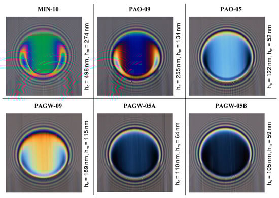
Figure 5.
Measured interferograms at ϑOil = 40 °C, pH = 530 N/mm2, v∑ = 1.6 m/s, and s = 0%.
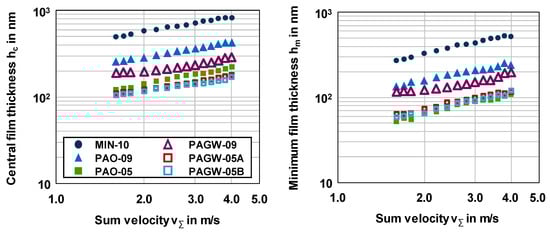
Figure 6.
Measured central and minimum film thickness hc (left) and hm (right) over the sum velocity v∑ at ϑOil = 40 °C, pH = 530 N/mm2, and s = 0%.
Based on the measured central film thickness hc in Figure 6, the pressure–viscosity coefficients αp of the lubricants considered can be derived using the Hamrock et al. [28] formula:
where U is the velocity parameter, G the material parameter, and W the load parameter:
The derived pressure–viscosity coefficients αp are summarized in Table 4. The coefficients can be classified according to the base oil type. The mineral oil MIN-10 shows the highest αp-value, which is approximately 1.7-fold the αp-values of the polyalphaolefin oils PAO-09 and PAO-05 and approximately 4.3-fold the αp-values of the water-containing gear fluids PAGW-09, PAGW-05A, and PAGW-05B. Note that the lubricant film thickness formation of the water-containing gear fluids is supported by the approximately 30% higher density, which goes in Equation (5) by the power of 0.67.
Table 4.
Derived pressure–viscosity coefficients from the optical EHL tribometer for investigated lubricants.
The results from the EHL optical tribometer show that the investigated water-containing lubricants have good EHL lubricant film formation capability.
4.2. Twin-Disk Test Rig
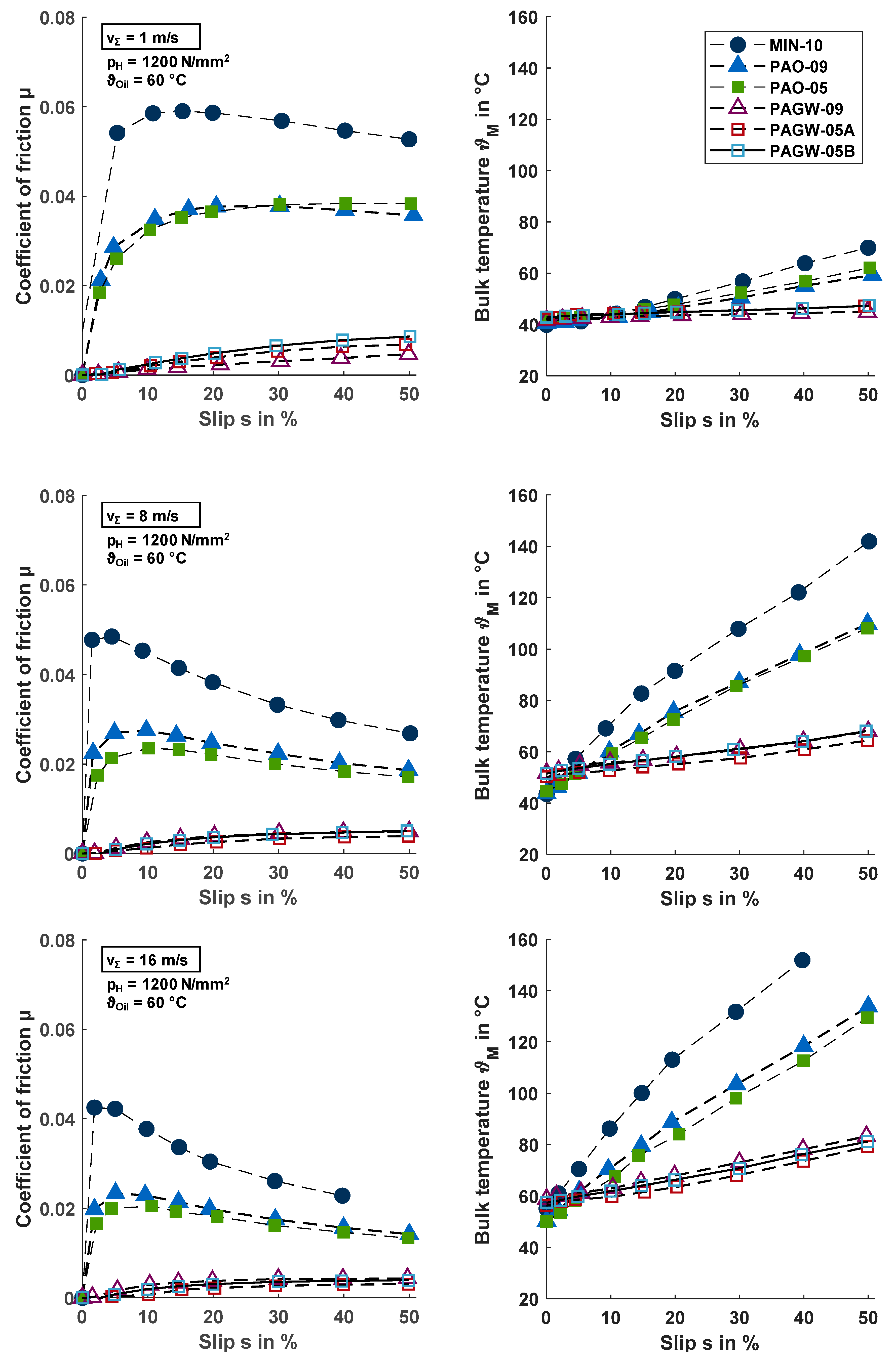
Figure 7 shows the averaged measured coefficients of friction µ and bulk temperatures ϑM over the slip ratio s for an oil inlet temperature of ϑOil = 60 °C, a Hertzian pressure of pH = 1200 N/mm2, and sum velocities vΣ = {1; 8; 16} m/s. All friction curves measured were repeated once with the same disk pairs. The maximum deviation was 0.0004 for MIN-10, 0.0011 for PAO-09, 0.0022 for PAO-05, 0.0028 for PAGW-09, 0.0013 for PAGW-05A, and 0.0006 for PAGW-05B.
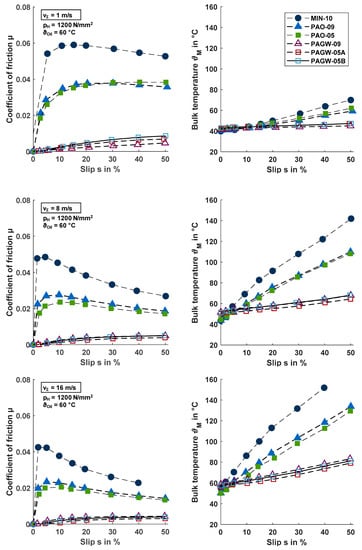
Figure 7.
Measured coefficients of friction µ and related bulk temperatures ϑM for ϑOil = 60 °C, pH = 1200 N/mm2, and vΣ = {1; 8; 16} m/s.
In the case of the conventional gear oils MIN-10, PAO-09, and PAO-05, all friction curves show a typical behavior, as described in Section 1. A strong increase of the coefficient of friction is followed by a maximum value at low slip ratios. With higher slip ratios, the friction curves become dominated by thermal effects due to the increase of friction power in the disk contact. The bulk temperatures ϑM as measure for the friction power increase continuously with the slip ratio and more strongly for higher sum velocities. The two polyalphaolefin oils PAO-09 and PAO-05 show considerably lower coefficients of friction than the mineral oil MIN-10, whereas the influence of the viscosity difference between PAO-09 and PAO-05 is small. These findings correlate well with the general findings of Mayer [1]. The lowest coefficient of friction of the conventional gear oils was observed for PAO-05.
In the case of the water-containing gear fluids PAGW-09, PAGW-05A, and PAGW-05B, significantly lower coefficients of friction and bulk temperatures were measured compared to the conventional gear oils. In fact, all coefficients of friction were lower than μ < 0.01, which is the value that classifies superlubricity (Hirano et al. [29]). Contrary to the conventional gear oils, the coefficients of friction increase steadily with increasing slip ratio. No strong increase or pronounced maximum at low slip ratios was found. Some influence of thermal effects can be seen due to the flattening of friction curves at high slip ratios, which was particularly pronounced for higher sum velocities due to higher friction power. Corresponding to the ultra-low coefficients of friction µ, the bulk temperatures ϑM were much smaller compared to the conventional gear oils.
For estimation of the lubrication regime in the experiments, the relative film thickness λrel can be used:
The minimum film thickness hm for line contacts was calculated according to Dowson et al. [30] with values for αp adopted from Table 4. Fluid film lubrication was assumed for λrel > 3. Table 5 shows the calculated relative film thickness λrel for pH = 1200 N/mm2, vΣ = {1; 8; 16} m/s, and s = {0; 50}%. It indicates fluid film lubrication for all considered operating conditions. The lowest λrel values occur for PAO-05, PAGW-05A, and PAGW-05B at v∑ = 1 m/s, where some asperity contact cannot be excluded. This may correspond to the slightly lower friction of PAGW-09 at v∑ = 1 m/s in Figure 7.
Table 5.
Calculated relative film thickness λrel for pH = 1200 N/mm2, vΣ = {1; 8; 16} m/s, and s = {0; 50}%.
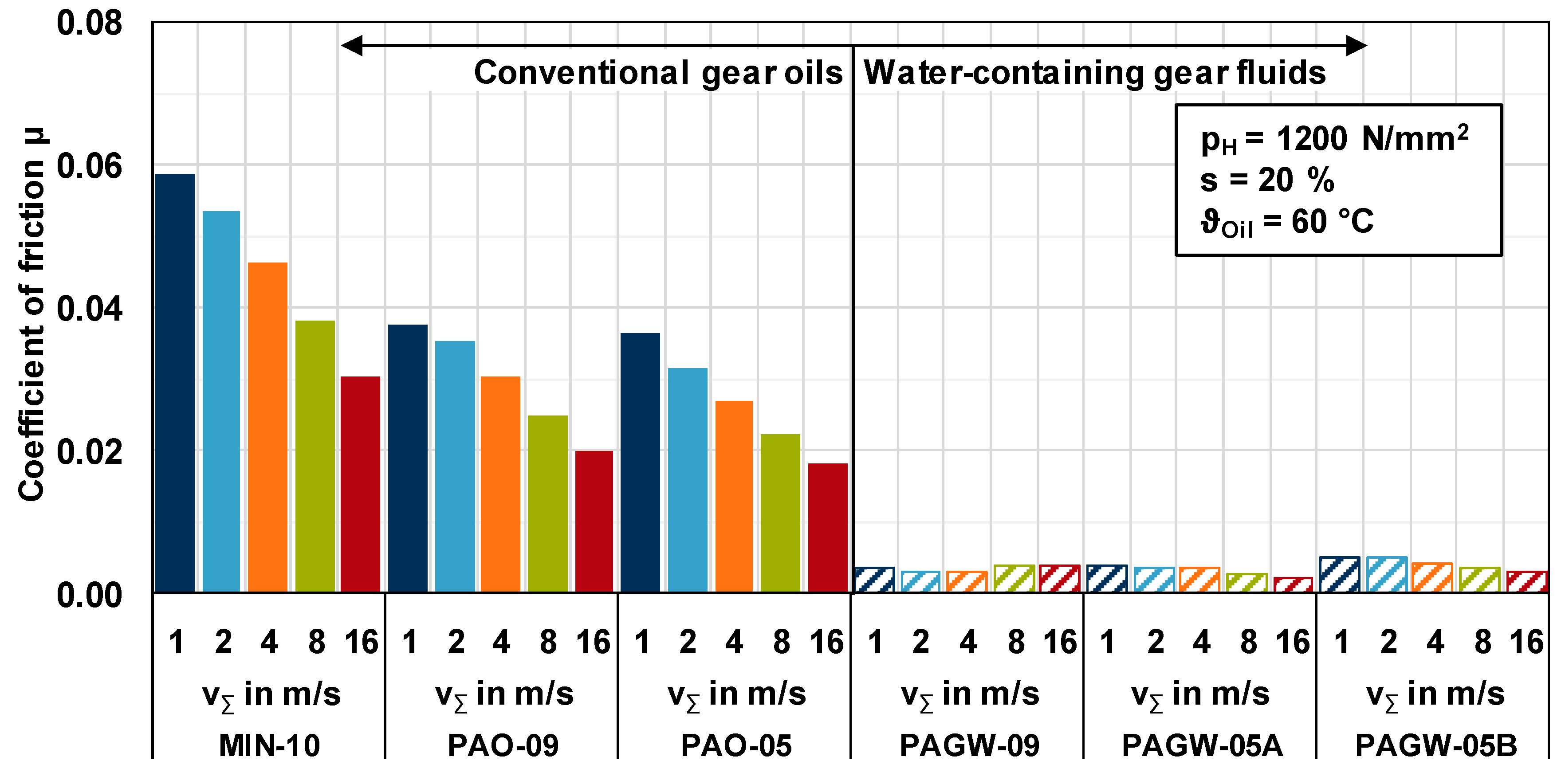
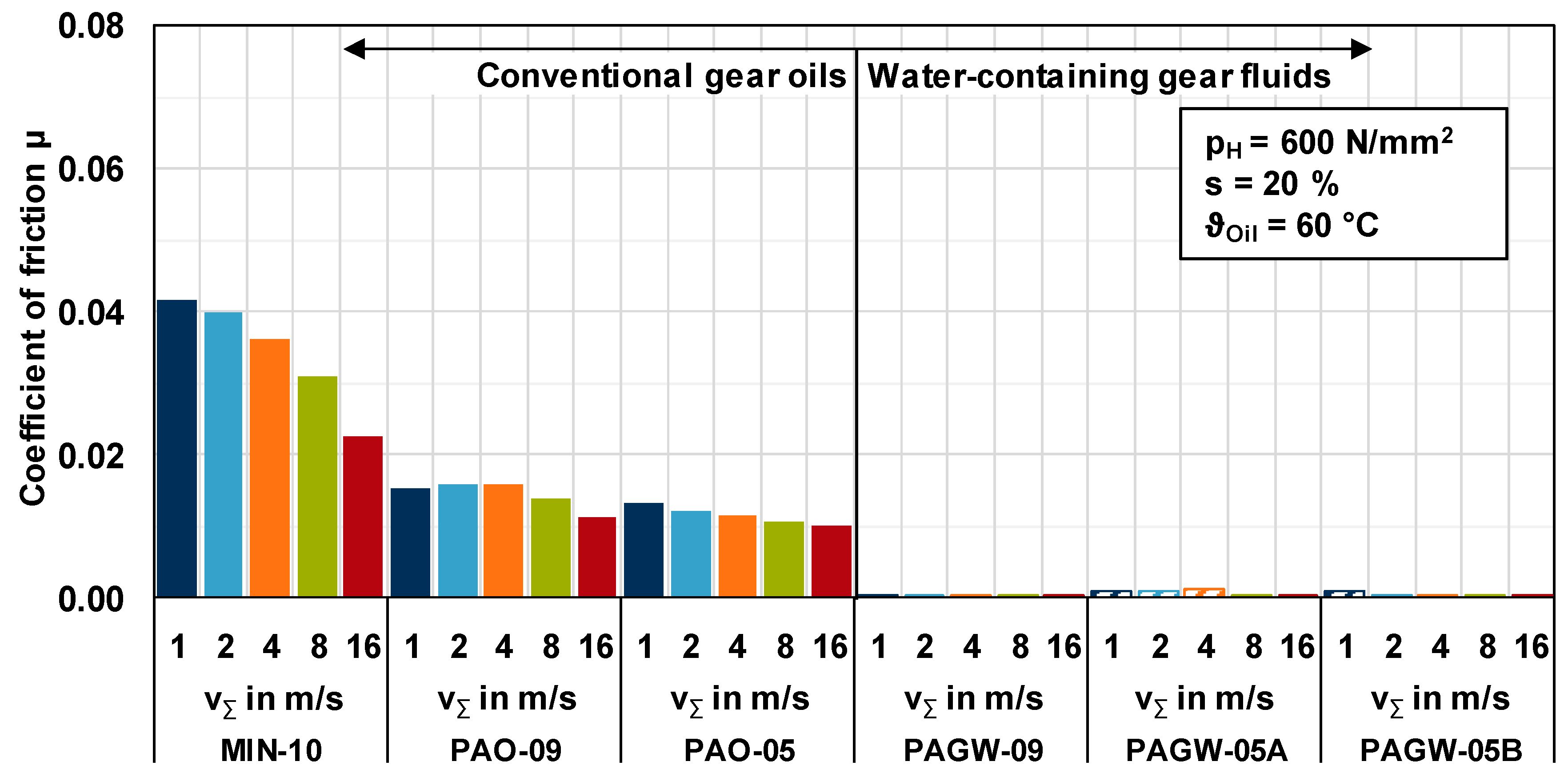
Figure 8 and Figure 9 summarize the averaged measured coefficients of friction µ for an oil inlet temperature of ϑOil = 60 °C, Hertzian pressures of pH = {600; 1200} N/mm2, and sum velocities of vΣ = {1; 2; 4; 8; 16} m/s for a slip ratio of s = 20%. For all lubricants considered, the coefficients of friction measured were lower for the lower Hertzian pressure of pH = 600 N/mm2. Again, ultra-low coefficients of friction were measured with the water-containing gear fluids for all operating conditions considered. The coefficient of friction was always lower than μ < 0.01, corresponding to superlubricity.

Figure 8.
Comparison of measured coefficients of friction µ at ϑOil = 60 °C, pH = 1200 N/mm2, vΣ = {1; 2; 4; 8; 16} m/s, and s = 20%.
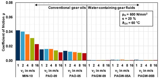
Figure 9.
Comparison of measured coefficients of friction µ at ϑOil = 60 °C, pH = 600 N/mm2, vΣ = {1; 2; 4; 8; 16} m/s, and s = 20%.
The friction behavior measured at the twin-disk test rig was very different in comparison to the conventional gear oils and water-containing gear fluids. The conventional gear oils MIN-10, PAG-09, and PAO-05 show coefficients of friction between 0.020 ≤ µ ≤ 0.060 and friction curve behavior typically known from highly-loaded EHL contacts. The water-containing gear fluids PAGW-09, PAGW-05A, and PAGW-05B show ultra-low coefficients of friction below µ < 0.010 in the superlubricity regime, and atypical friction curve behavior with a steady increase of friction over slip ratio.
As the pressure–viscosity coefficients and lubricant film formation of the water-containing gear fluids was evaluated as fairly good, its ultra-low friction cannot be referred to low contact viscosities as stated for water-based fluids with low pressure–viscosity coefficient. Existing model representations for the ultra-low friction of water-containing fluids were summarized in Section 1. According to Chen et al. [13], a microscopic layer of FeOOH is built on the substrate in ambient conditions, accumulating a hydrogen-bonded film of glycol and water molecules. Between these films, there is a zone of free water molecules allowing easy sliding, which results in ultra-low friction. A similar mechanism may apply for the water-containing gear fluids considered.
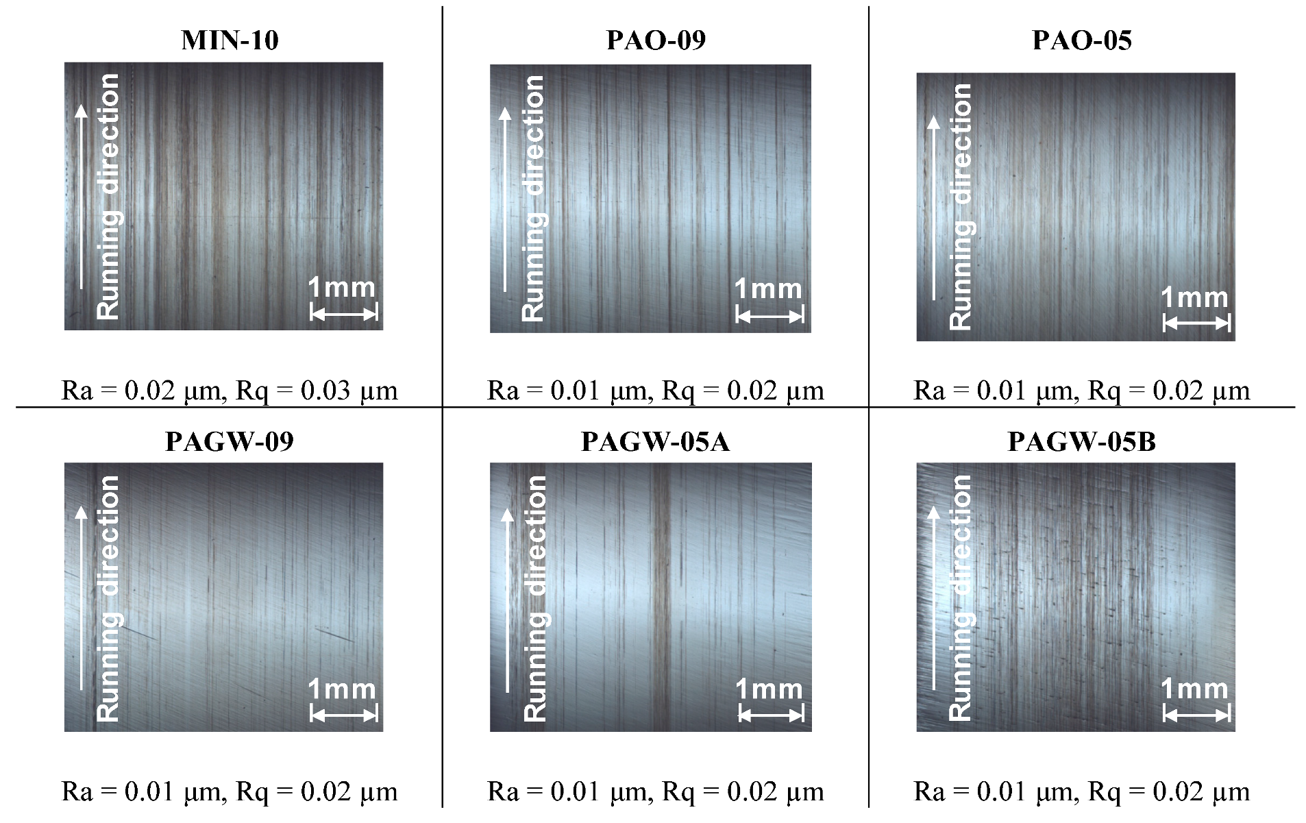
Figure 10 shows light microscope pictures and roughness parameters Ra and Rq of the upper disk after test runs. For all surfaces, typical light circumferential marks on the disk surfaces were observed. The arithmetic mean surface roughness value shows no significant change compared to the initial condition, whereas the root-mean-squared roughness shows a slight increase.
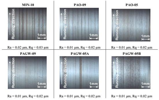
Figure 10.
Light microscope pictures and roughness parameters Ra and Rq of upper disk surfaces after test runs.
5. Conclusions
This study investigated the film formation and frictional behavior of highly-loaded EHL contacts with water-containing gear fluids. The film thickness measurements at the optical EHL tribometer showed good film formation capability. In comparison to polyalphaolefin oils with similar kinematic viscosity, the lubricant film thickness was only slightly smaller and supported by the approximately 30% higher density. The friction measurements at the twin-disk test rig showed ultra-low friction in the superlubricity regime. The friction curves increase steadily over the slip ratio. Thermal effects play a subordinate role. The results of this study indicate that the water-containing fluids considered have significant potential for gear applications in terms of efficiency and heat balance.
Author Contributions
M.Y. designed the experiments, analyzed the results and wrote the paper. M.M. carried out the twin-disk tests and supported the interpretation of the results. T.L. participated in the scientific discussions and revised the paper. K.S. proof read the paper.
Funding
This publication uses results from a project that has been funded by the German Federal Ministry for Economic Affairs and Energy with funding reference 03ET1286H. This publication is supported by the Technical University of Munich (TUM) in the framework of the Open Access Publishing Program. The author is responsible for the content of this publication.
Acknowledgments
Special thanks go to Nils Tärnhuvud for performing the experiments on the optical EHL tribometer.
Conflicts of Interest
The authors declare no conflict of interest.
Nomenclature
| Reduced Young’s Modulus | N/mm2 | |
| Normal force | N | |
| Friction force | N | |
| G | Material parameter | - |
| hc | Central film thickness | nm |
| hm | Minimum film thickness | nm |
| Hertzian pressure | N/mm2 | |
| U | Velocity parameter | - |
| Ra | Arithmetic mean roughness | µm |
| Rq | Root-mean-squared mean roughness | µm |
| Reduced radius | mm | |
| Slip | % | |
| Time | s | |
| Sliding velocity | m/s | |
| Sum velocity | m/s | |
| W | Load parameter | - |
| Greek symbols | ||
| αp | Pressure–viscosity coefficient | 1/GPa |
| η | Dynamic viscosity | Pa |
| κ | Ellipticity parameter | - |
| λrel | Relative film thickness | - |
| Coefficient of friction | - | |
| Bulk temperature | °C | |
| Oil temperature | °C | |
| Kinematic viscosity | mm2/s | |
| Indices | ||
| 1 | Lower disk | |
| 2 | Upper disk |
References
- Mayer, J. Einfluss der Oberfläche und des Schmierstoffs auf das Reibungsverhalten im EHD-Kontakt (Influence of surface texture and lubricant on the frictional behaviour of EHL contacts). Ph.D. Thesis, Technical University of Munich, Munich, Germany, 2013. [Google Scholar]
- Bobach, L.; Bartel, D.; Beilicke, R.; Mayer, J.; Michaelis, K.; Stahl, K.; Bachmann, S.; Schnagl, J.; Ziegele, H. Reduction in EHL Friction by a DLC Coating. Tribol. Lett. 2015, 60, 17. [Google Scholar] [CrossRef]
- Bader, N.; Wang, D.; Poll, G. Traction and local temperatures measured in an elastohydrodynamic lubrication contact. Proc. Inst. Mech. Eng. 2017, 231, 1128–1139. [Google Scholar] [CrossRef]
- Evans, C.R.; Johnson, K.L. The rheological properties of elastohydrodynamic lubricants. Proc. Inst. Mech. Eng. Sci. 1986, 200, 303–312. [Google Scholar] [CrossRef]
- Björling, M.; Larsson, R.; Marklund, P. The Effect of DLC Coating Thickness on Elastohydrodynamic Friction. Tribol. Lett. 2014, 55, 353–362. [Google Scholar]
- Ndiaye, S.-N.; Martinie, L.; Philippon, D.; Devaux, N.; Vergne, P. A Quantitative Friction-Based Approach of the Limiting Shear Stress Pressure and Temperature Dependence. Tribol. Lett. 2017, 65, 149. [Google Scholar] [CrossRef]
- Bair, S.; Winer, W.O. Shear Strength Measurements of Lubricants at High Pressure. J. Lubr. Technol. 1979, 101, 251–257. [Google Scholar] [CrossRef]
- Martinie, L.; Vergne, P. Lubrication at Extreme Conditions: A Discussion About the Limiting Shear Stress Concept. Tribol. Lett. 2016, 63, 21. [Google Scholar] [CrossRef]
- Bair, S. The viscosity at the glass transition of a liquid lubricant. Friction 2019, 7, 86–91. [Google Scholar]
- Bair, S.; Yamaguchi, T.; Brouwer, L.; Schwarze, H.; Vergne, P.; Poll, G. Oscillatory and steady shear viscosity: The Cox-Merz rule, superposition, and application to EHL friction. Tribol. Int. 2014, 79, 126–131. [Google Scholar] [CrossRef]
- Sagraloff, N.; Dobler, A.; Tobie, T.; Stahl, K.; Ostojewski, J. Development of an oil free water-based lubricant for gear apllications. Lubricants 2019, 7, 33. [Google Scholar] [CrossRef]
- Martin, J.M.; De Barros-Bouchet, M.I. Water-Like Lubrication of Hard Contacts by Polyhydric Alcohols. Aqueous Lubr. Nat. Biometric Approaches 2014, 3, 219–235. [Google Scholar]
- Chen, Z.; Liu, Y.; Zhang, S.; Luo, J. Controllable Superlubricity of Glycerol Solution via Environment Humidity. Langmuir 2013, 29, 11924–11930. [Google Scholar] [CrossRef]
- Li, J.; Zhang, C.; Luo, J. Superlubricity Achieved with Mixtures of Polyhydroxy Alcohols and Acids. Langmuir 2013, 29, 5239–5245. [Google Scholar] [CrossRef]
- Li, J.; Zhang, C.; Ma, L.; Liu, Y.; Luo, J. Superlubricity Achieved with Mixtures of Acids and Glycerol. Langmuir 2013, 29, 271–275. [Google Scholar] [CrossRef]
- Wang, H.; Liu, Y.; Li, J.; Luo, J. Investigation of Superlubricity Achieved by Polyalkylene Glycol Aqueous Solutions. Adv. Mater. Interfaces 2016, 3, 1600531. [Google Scholar] [CrossRef]
- Yilmaz, M.; Mirza, M.; Lohner, T.; Stahl, K. Superlubricity in EHL Contacts with Water-Containing Gear Fluids. In Proceedings of the 7th European Conference on Tribology, Vienna, Austria, 12–14 June 2019. [Google Scholar]
- Laukotka, E.M. FVA-Heft Nr. 660—Referenzöle Datensammlung; Forschungsvereinigung Antriebstechnik e.V.: Frankfurt/Main, Germany, 2007. [Google Scholar]
- Slope, M. DIN 51563. Prüfung von Mineralölen und verwandten Stoffen—Bestimmung des Viskosität-Temperatur-Verhaltens—Richtungskonstante (Testing of Mineral Oils and Related Materials—Determination of Viscosity Temperature Relation); DIN—German Institute for Standardization: Berlin, Germany, 1976. [Google Scholar]
- Omasta, M.; Ebner, M.; Sperka, P.; Lohner, T.; Krupka, I.; Hartl, M.; Höhn, B.-R.; Stahl, K. Film formation in EHL contacts with oil-impregnated sintered materials. Ind. Lubr. Tribo. 2018, 70, 612–619. [Google Scholar] [CrossRef]
- Ebner, M.; Omasta, M.; Lohner, T.; Sperka, P.; Krupka, I.; Hartl, M.; Michaelis, K.; Höhn, B.-R.; Stahl, K. Local Effects in EHL Contacts with Oil-Impregnated Sintered Materials. Lubricants 2019, 7, 1. [Google Scholar] [CrossRef]
- Hartl, M.; Krupka, I.; Liska, M. Differential colorimetry: tool for evaluation of chromatic interference patterns. Opt. Eng. 1997, 39, 2384–2391. [Google Scholar] [CrossRef]
- Molimard, J.; Querry, M.; Vergne, P.; Krupka, I.; Hartl, M.; Poliscuk, R.; Liska, M. Differential Colorimetry: A tool for the analysis of fluid film lubrication. Mec. Ind. 2002, 3, 571–581. [Google Scholar]
- Stößel, K. Reibungszahlen unter elasto-hydrodynamischen Bedingungen (Coefficients of friction under elastohydrodynamic conditions). Ph.D. Thesis, Technical University of Munich, Munich, Germany, 1971. [Google Scholar]
- Lohner, T.; Merz, R.; Mayer, J.; Michaelis, K.; Kopnarski, M.; Stahl, K. On the Effect of Plastic Deformation (PD) Additives in Lubricants. Tribol. Schmierungstech. 2015, 62, 13–24. [Google Scholar]
- Ebner, M.; Lohner, T.; Michaelis, K.; Stemplinger, J.-P.; Höhn, B.-R.; Stahl, K. Self-Lubricated Elastohydrodynamic (EHL) Contacts with Oil-Impregnated Sintered Materials. In Proceedings of the TAE Esslingen 20th International Colloquium, Tribology—Industrial and Automotive Lubrication, Stuttgart, Germany, 12–14 January 2016. [Google Scholar]
- Yilmaz, M.; Kratzer, D.; Lohner, T.; Michaelis, K.; Stahl, K. A study on highly-loaded contacts under dry lubrication for gear applications. Tribol. Int. 2018, 128, 410–420. [Google Scholar] [CrossRef]
- Hamrock, B.J.; Dowson, D. Isothermal Elastohydrodynamic Lubrication of Point Contacts. J. Lubr. Technol. 1977, 99, 264–276. [Google Scholar] [CrossRef]
- Hirano, M.; Shinjo, K. Atomistic locking and friction. Phys. Rev. B 1990, 41, 11837–11851. [Google Scholar] [CrossRef]
- Dowsonn, D.; Higginson, G.R. Elastohydrodynamic Lubrication—The Fundamental of Roller and Gear Lubrication; Perganom Press: Oxford, UK, 1966. [Google Scholar]
© 2019 by the authors. Licensee MDPI, Basel, Switzerland. This article is an open access article distributed under the terms and conditions of the Creative Commons Attribution (CC BY) license (http://creativecommons.org/licenses/by/4.0/).