Article

The Impact of Lubricant Film Thickness and Ball Bearings Failures †

by
Matthew David Marko
Naval Air Warfare Center Aircraft Division, Joint-Base McGuire-Dix-Lakehurst, Lakehurst, NJ 08733, USA
NAVAIR Public Release 2018-609 Distribution Statement A—“Approved for public release; distribution is unlimited”.
Lubricants 2019, 7(6), 48; https://doi.org/10.3390/lubricants7060048
Submission received: 14 February 2019 / Revised: 22 May 2019 / Accepted: 30 May 2019 / Published: 2 June 2019

Abstract

:
An effort was made to find a relationship between the lubricant thickness at the point of contact of rolling element ball bearings, and empirical equations to predict the life for bearings under constant motion. Two independent failure mechanisms were considered, fatigue failure and lubricant failure resulting in seizing of the roller bearing. A theoretical formula for both methods was established for the combined probability of failure using both failure mechanisms. Fatigue failure was modeled with the empirical equations of Lundberg and Palmgren and standardized in DIN/ISO281. The seizure failure, which this effort sought to investigate, was predicted using Greenwood and Williamson’s theories on surface roughness and asperities during lubricated contact. These two mechanisms were combined, and compared to predicted cycle lives of commercial roller bearing, and a clear correlation was demonstrated. This effort demonstrated that the Greenwood–Williams theories on the relative height of asperities versus lubricant film thickness can be used to predict the probability of a lubricant failure resulting in a roller bearing seizing during use.

1. Introduction

Ball bearings are used in countless mechanical applications to convert sliding mechanical contact into rolling contact [1,2,3], dramatically reducing friction energy losses. Sliding contact inherently has a high friction force, as random asperities can contact the surface and induce wear and damage to machined parts [4,5,6,7,8,9]. Rolling contact, however, has dramatically lower friction; the overwhelming majority of the friction loss is merely hysteresis from elastic deflections of the circular bearings.
Rolling element bearings are one of the most common configuration of ball bearings, with the bearings contained in a circular race to allow continued circular motion. As long as there is a minimum surface friction to enable the bearings to roll, there will be a dramatic reduction in circular friction for an object spinning inside or outside of the races. Bearings can be spherical, cylindrical, or a host of different configurations depending on the applications of the ball bearings.
A well built bearing can last indefinitely, however all mechanical objects have some risk of failure. Despite the previous assumptions that stresses less than half of yield have no significant risk of failure, there is always some risk of fatigue and fracture, which may manifest itself in the life of a ball bearing. The most likely bearing failure, however, is lubricant failure causing the bearings to seize. Ball bearings overwhelmingly use lubricant oils and greases to ensure there is not an excessive build-up of heat and friction between the races and the bearings. While a minimum amount of friction is necessary to ensure the bearings roll rather than slide (often specified as a minimum axial load), too much friction can cause the bearings to stick to the race and seize up, rather than allowing rolling.
Friction is inherently random and variable, as it is impacted by the different random surface asperities; as such, it is incredibly difficult to model. The usual (but not exclusive) mechanism of lubricant failure is as follows: a high enough friction will heat the lubricant, which will reduce the viscosity of the lubricant, which will increase the friction heating, and this feedback loop will continue until the friction between the bearing and the races is so great that the bearing seizes. If a bearing seizes during a critical application, the results can be catastrophic.
While it is impossible to truly know the exact nature of every bearing surface, empirical equations can be generated to determine the L 10 life from a known bearing load, lubricant cleanliness, lubricant viscosity, and continuous bearing speed. The L 10 life is defined as the number of revolutions a bearing can experience before a 10% chance of bearing failure. This effort was to study how tribological properties such as the lubricant film thickness [10,11,12] can serve to predict the change of failure after a single revolution, and thus estimate the L 10 life.

2. Empirical Equations for L 10 Life

To properly develop a numerical model for ball bearing failures, it is necessary to have empirical data on bearing failure to verify and validate it. In this aim, the L 10 empirical equations provided by Timken [13] was used as a basis for validating predictions of bearing life as a function of lubricant thickness. The world’s largest manufacturer of ball bearings is Svenska Kullagerfabriken (SKF), a Swedish company founded in 1907; they use a bearing life calculator [14,15] similar to Timken as well. Timken’s life equations were provided in easily duplicated empirical equations, versus a software life calculator; for the purpose of this analysis, Timken was used. These Timken empirical equation ultimately yield the L 10 life in revolutions before the bearings have a 10% chance of failure. The core equation for L 10 life is [13]
L 10 = A 10 · ( C a 1 P ) p ^ · 10 6 ,
where C a 1 (N) is the basic dynamic load rating, P (N) is the equivalent load, and A 10 is the life modification factor. The value of p ^ was found empirically, and it is 3 for spherical bearings and 10/3 for cylindrical bearings [16,17,18], based on empirical research of Lundberg and Palmgren [16,17,18].
The value of A 10 is a function of several dimensionless parameters
A 10 = a 1 · a 2 · C g · C l · C j · C s · C v · C g r ,
where a 2 is a material factor that was treated as 1 for steel bearings; C g is a geometry factor set to 1 for spherical roller bearings; G g r is the grease factor that is set to 1 if not using grease and 0.79 with grease; a 2 is a material factor set to 1 for steel bearings; and C j ranges between 0.747 and 1.0, depending on how tapered the bearing is, and this simulation assumed C j = 1 for non-tapered bearings. The value of C l is inverse proportional to the equivalent load P (N)
C l = P 0.25 , P = F a + 1.2 · F r ,
where F a (N) and F r (N) are the axial and radial loads. The speed factor is proportional to the square root of the speed in revolutions per minute
C s = Ω R P M ,
and the viscosity factor C v is proportional to the square root of the kinematic viscosity ν (cSt) in centistokes
C v = 1.6 · ν .
Finally, the factor a 1 is set to the probability of failure of interest,
a 1 = 4.26 · ( l o g 100 R ) 2 / 3 + 0.05 ,
where R represents the probability of surviving the calculated number of cycles. If R = 90, to represent L 10 , then the value of a 1 is 1.

3. Tribological Predictions of L 10 Life

Equation (1) can predict the L 10 , but it gives no information as to the mechanics of the failure; it is purely based on empirical data. To better understand the mechanism of failure, a model based on the tribological properties to find the values of L 10 needs to be developed, with Equation (1) being used to verify and validate this model.
Regardless of the L 10 life, a ball bearing failure can happen; L 10 life is really a function of the probability of failure in the face of random conditions such as surface asperities. One common form of bearing failure is seizure, where excessive friction can yield increased heating, which reduces the lubricant viscosity, increasing the friction; eventually, the friction increases until it is high enough that the bearing seizes. Another potential cause of failure is a failure in fatigue; this increases exponentially with increasing load relative to fatigue life. For the purpose of the analysis, the driving cause of failure is treated as an excessively high increase in friction from the approximated average friction.
The greater the lubricant thickness is at the point of elastohydrodynamic contact, the less wear and friction can be expected. According to Greenwood and Williamson’s research [19,20,21,22,23,24], wear and friction (other than from fluid stresses, and hysteresis of rolling contact) occur due to random asperities exceeding the thickness of the lubricant film [19,20,21,22,23,24,25,26]; the thicker is the lubricant, the lower is the mean ratio of true contact area ratio [1,27]. Assuming the surface asperities height follows a normal distribution, the ratio of metal-on-metal contact A r e a l / A with the lubricant thickness should roughly follow
A r e a l A e x p ( h σ ) ,
where A r e a l (m 2 ) represents the true metal-on-metal contact area, A (m 2 ) represents the apparent (but not true) surface contact area, h (m) represents the lubricant film thickness, and σ (m) represents the RMS average asperities height. In addition to the fatigue life, where the failure life is proportional to the load over the fatigue load to the power of 10/3, it is expected that the L 10 probability of lubricant failure will be a function of the lubricant film thickness h (m)
L 10 = f ( h ) + f ( C a 1 P )

4. First Parametric Study

The simulation assumed a lubricant with an ISO Viscosity Grade of 46, with a kinematic viscosity of 46 cSt at 40 C, and kinematic viscosity of 8.5 cSt at 100 C, lubricant properties of a typical commercially available bearing gear oil (Mobil SHC 625). The temperature range in the simulation was varied from 20 C to 300 C (112.2355 cSt to 1.0648 cSt). A copy of the Matlab computer code for this simulation is included in the Supplementary Materials.
A parametric study was conducted, utilizing the Timken 29348 roller bearing. This has an inner bore of 240 mm, a dynamic load rating C a 1 of 2,040 kN, and an average roller diameter of 315.7 mm. While the roller diameters are not clearly specified, CAD estimation yielded a length of 49.68 mm and an average roller radius of 18.87 mm, with a total of 23 rollers. The bearing is made of steel, thus the Young’s modulus E Y is 210 GPa, and the Poisson’s ratio p is 0.3. The parametric study calculated both the L 10 life as defined in Equation (1), and compared it to the predicted lubricant film thickness [10,11,12,28,29,30,31,32,33,34,35,36,37,38,39,40], and the relative fatigue load. The parametric study was conducted for a temperature ranging between 20 C and 300 C, in increments of 10 C; an equivalent axial load of 1–100% (in 1% increments) of the 2,040 kN dynamic load C a 1 ; and a bearing speed of 1,000–15,000 RPM, in increments of 500 RPM. With each of these parameters, the L 10 life was calculated with Equation (1).
The next step was to predict the film thickness of the lubricant at the point of contact between the bearings and the rollers during elastohydrodynamic contact [1,41,42,43,44,45,46,47,48]. In 1974, empirical equations by Hamrock and Dowson [33] characterized the minimum h 0 (m) and central h c (m) film thickness
h m i n = 3.63 R ( U n 0.68 ) ( G n 0.49 ) ( W n 0.073 ) ( 1 e x p [ 0.68 κ e l l i p s e ] ) ,
h c = 2.69 R ( U n 0.67 ) ( G n 0.53 ) ( W n 0.067 ) ( 1 0.61 · e x p [ 0.73 κ e l l i p s e ] ) ,
U n = μ 0 U E R ,
G n = α P V C E ,
W n = W E R 2 ,
where h m i n (m) is the minimum film thickness, h c (m) is the central film thickness, U n is the dimensionless speed parameter, G n is the dimensionless material parameter, W n is the dimensionless load parameter, κ e l l i p s e is the ellipticity of the contact area, μ 0 (Pa·s) is the dynamic viscosity of the lubricant at atmospheric pressure, and α P V C (Pa 1 ) is the pressure viscosity coefficient
α P V C = ( 0.965 · l o g 10 ( ν ) + 0.6 ) · 10 8 ,
where ν is the kinematic viscosity (m 2 /s) and U (m/s) is the velocity of contact. The reduced Young’s modulus E’ (Pa) and reduced radius R’ (m) are for Hertz contact equations for elastic deflection [1,49]. Assuming cylindrical rollers and a consistent material were used, the equations for E’ (Pa) and R’ (m) are
R = 1 / { 1 R r + 1 R R } ,
E = E Y 1 p 2 .
where R r (m) is the radius of the cylindrical bearing roller, R R (m) is the radius of the bearing race, and E Y (Pa) and p are the Young’s modulus and Poisson’s ratio of the bearing material.
To realize the minimum h m i n and central h c elastohydrodynamic film thickness, it is necessary to determine the dynamic viscosity of the lubricant. The viscosity of the lubricant, however, is affected by temperature [2,50,51,52,53], as hotter oils are inherently less viscous. A reduction in viscosity results in a reduced minimum film thickness [33], but this reduced film thickness results in a cooler oil film [29], as there is less thermal resistance from the center of the oil film to the surface of the ball bearing. As a result of this contradiction, it is necessary to use iteration to converge on a realistic lubricant oil temperature and viscosity, so that a minimum film thickness can be determined.
The first step is to calculate the flash temperature heating of the surface of the ball bearing. This is done by first calculating the dimensionless Peclet number [1,29]
L = U · b H 2 α b b ,
where b H (m) is the length of contact, also defined as the Hertzian half width of the contact between the roller and the race [1]
b H = 4 · W · R π · L r · E Y ,
where L r (m) is the half length of the roller, and α b b (m 2 /s) is the thermal diffusivity [54] of the ball bearing,
α b b = k b b ρ b b · C P , b b ,
where k b b ( W / m 2 · C ) is the thermal conductivity, ρ b b (kg/m 3 ) is the density, and C P , b b ( J / kg · C) is the specific heat capacity; all of these b b parameters are for the ball bearing material (steel).
Once the dimensionless Peclet number L is known, one can calculate the average flash temperature [55,56,57,58], which is defined as the temperature that results from the high-pressure and heating. For L < 0.1 , the friction heating is considered a stationary heat source, where the temperature distribution is effectively steady state, where the heat flow can be considered a flow of thermal current through a thermal resistance of the ball bearing. For 0.1 < L < 5.0 , the friction heating is considered a slow-moving heat source, where there is ample time for the temperature to be conducted through the ball bearing, and for L > 5.0 the friction heating is considered a high-speed heat source [29]. In this study, consistently the Peclet number has always exceeded the value of 5.
The predictive analytical equation used by this model for average flash temperature can vary with Peclet number, but the flash heating for Peclet numbers greater than 5 is [1,29]
Δ T F = 0.266 μ C O F · W · U k b b · b H α b b U · b H L > 5.0 ,
where μ C O F is the dimensionless coefficient of friction (COF), b H (m) is defined with Equation (18), W (N) is the load, and Δ T F ( C) is the surface temperature increase due to friction. The value of μ C O F is assumed to be 0.0018, which is a standard friction coefficient for the rolling resistance spherical roller bearings [13,14,15].
The friction temperature can be used to calculate the average viscosity [1,45,46,53], where
ν = Z ^ e x p [ 0.7487 3.295 · Z ^ + 0.6119 · Z ^ 2 0.3193 · Z ^ 3 ] , Z ^ = 10 [ 10 ( A B · l o g 10 T L ) ] 0.7
where ν (mm 2 /s) is the kinematic viscosity, and A and B are dimensionless coefficients derived empirically. They can be found by measuring the kinematic viscosity at two temperature points, calculating the Z-value [53],
Z = ν + 0.7 + e x p [ 1.47 1.84 ν 0.51 ν 2 ] ,
and obtaining the viscosity coefficients, where [53]
l o g 10 l o g 10 Z = A B · l o g 10 T , B = l o g 10 l o g 10 Z i l o g 10 l o g 10 Z j l o g 10 T j l o g 10 T i , A = l o g 10 l o g 10 Z i + B · l o g 10 T i ,
where T i , T j , Z i , and Z j are the temperature (Kelvin) and Z-coefficients at temperature points i and j. To convert the values of kinematic viscosity from cSt to m 2 / s , simply multiply it by 10 6 ; the kinematic viscosity ( m 2 / s ) can be used to calculate the dynamic viscosity μ (Pa·s) of the lubricant [59],
μ = ρ l u b · ν ,
and this value can be used to calculate the film thickness using the Hamrock–Dowson [33] empirical equations.
If there is a given friction force that will cause the bearings to seize, and the friction is affected by the ratio of the height of the surface asperities (which follow a normal distribution) over the lubricant film thickness, an accurate equation for L 10 in revolutions log 10 as a function of h c (m) is realized with Equation (25)
l o g 10 ( L 10 ) = b 1 + b 2 · ( P C a 1 ) 3 / 10 + b 3 · l o g ( h c ) ,
where h c (m) is the central film thickness in micrometers. Equation (25) incorporates two separate failure mechanisms, where b 2 is a coefficient for the rolling contact fatigue failure [16,17,18], and b 3 is a coefficient for the lubricant seizure based on friction (originating from Greenwood–Williams theory [19,20,21,22,23,24,25,26]). The fatigue life theory is an entirely different and independent failure mechanism from lubricant seizure; Equation (25) combines both potential failures into L 10 to obtain an overall probability of bearing failure during a given revolution.
The calculated value of L 10 found with Equation (25) closely matches the value of L 10 found with Equation (1), and is observed to match in Figure 1 for a Timken 29348 roller bearing. The coefficients for this particular design are b 1 = 18.7598 , b 2 = 7.6583 , and b 3 = 0.3086 , and the coefficient of determination R 2 between Equation (1) and Equation (25) is 0.96858, showing an extremely strong match.

5. Second Parametric Study

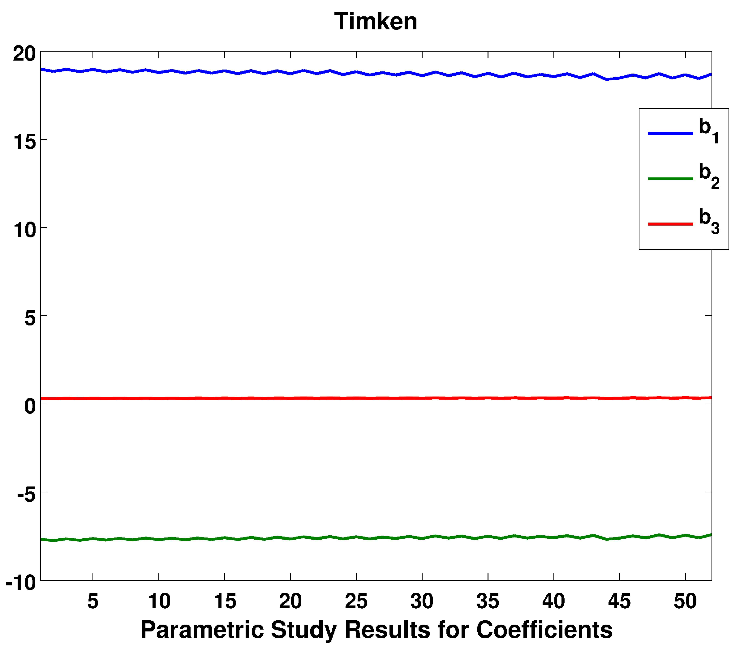
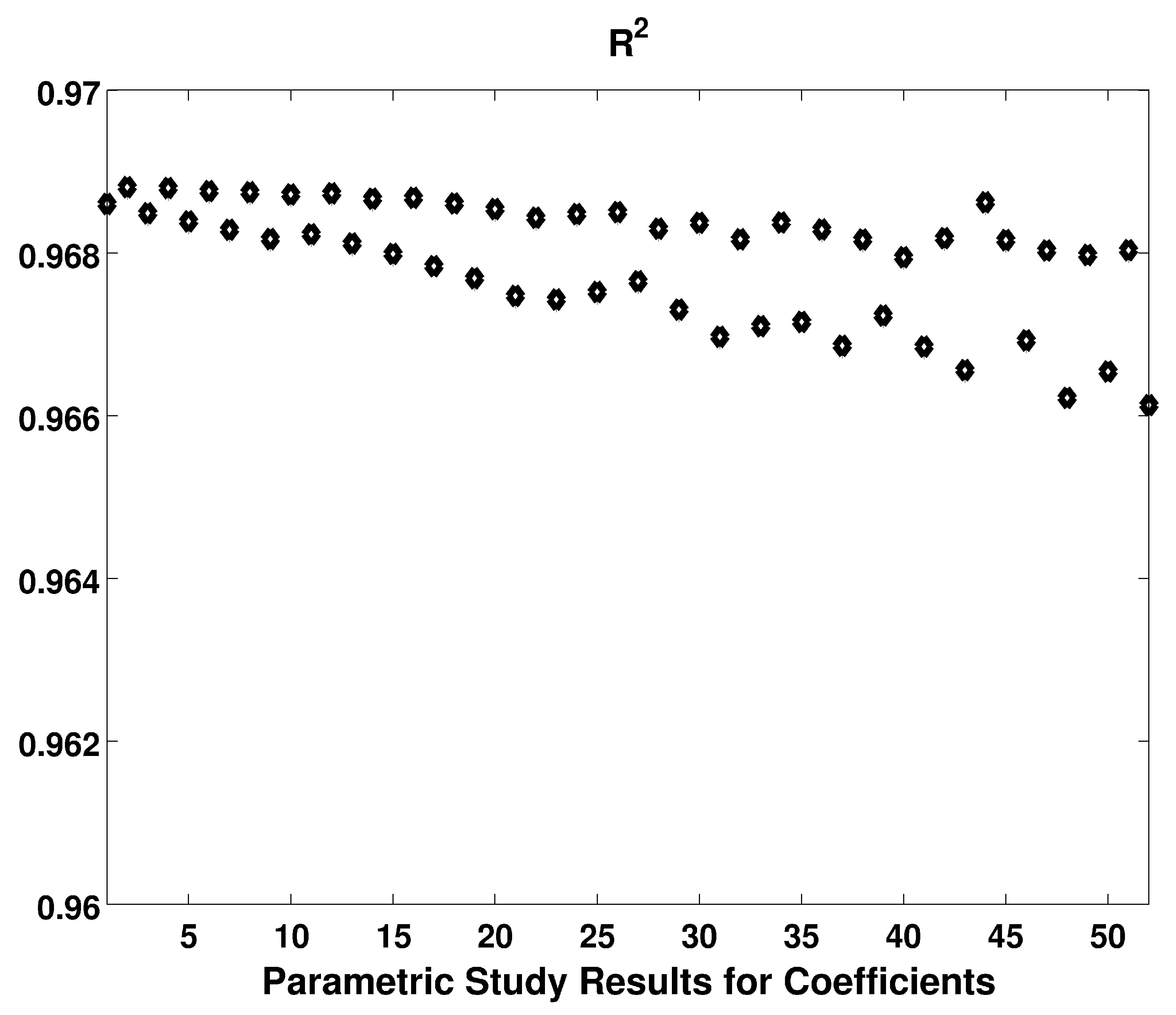
A second parametric was conducted to see if varying the bearing size would affect the coefficients for Equation (25), for 52 different spherical roller bearings, with dimensions tabulated in Table 1. The mean bearing radius was modeled from 90 mm to 480 mm. As observed in Figure 2, the three coefficients b 1 , b 2 , and b 3 vary slightly; the ratio of standard deviation to mean is well under 5%. The average values of the coefficients are b ¯ 1 = 18.73 , b ¯ 2 = 7.6 , and b ¯ 3 = 0.32 ; these values are nearly identical to the values found for the Timken 29348 described in Section 4. By plugging these values into Equation (25), a universal equation for the L 10 failure life for spherical roller bearing life could be obtained, presented as Equation (26). As observed in Figure 3, the coefficient of determination R 2 between this Equation (26) and the Timken equation (Equation (1)) never goes below 0.966, validating this theory of predicted lubricant thickness having a clear and calculable effect on the function life of roller bearings.
l o g 10 ( L 10 ) = 18.73 7.6 · ( P C a 1 ) 3 / 10 + 0.32 · l o g ( h c ) .
As a simple test, Equation (26) was compared to both the original Timken equation (Equation (1)) [13] and the SKF calculator [14], using the the Timken and SKF 29348 spherical roller thrust bearing, with the Mobil 625 oil (with a kinematic viscosity of 46 cSt at 40 C, and kinematic viscosity of 8.5 cSt at 100 C), at a temperature of 70 C (kinematic viscosity of 15.5429 cSt), a speed of 1,000 RPM, and an axial load of 408 kN (20% of the dynamic fatigue load of 2,040 kN). The calculated l o g 10 ( L 10 ) life with the Timken equation (Equation (1)) was 9.2495; the calculated l o g 10 ( L 10 ) life with Equation (26) was 9.4348, an error of less than 2%. The SKF calculator for the same dimension bearing, with the same speed, load, oil, and temperature, and a simplified lubricant cleanliness factor of 0.6 (middle range between dirtiest of 0.2 and cleanest of 1.0) is 31,700 h, which at 1,000 RPM corresponds to 1.902 billion revolutions; the l o g 10 ( L 10 ) of this value is 9.2792. It is clear that the Timken equation (Equation (1)) [13], the SKF calculator [14], and Equation (26) all yield comparable results, as a further validation of Equation (26).

6. Conclusions

A validated model to predict the probability of failures for roller bearings was developed. Empirical equations from Timken were developed from available data on commercial bearings to predict the L 10 life based on known bearing conditions (lubricant viscosity, bearing speed, and loads). These conditions were used, along with the roller bearing geometry, to predict the lubricant film thickness at the central point of contact. A thicker film thickness is expected to inherently have lower friction, and therefore a lower chance of lubricant failure, and a clear trend of lubricant thickness impacting the probability of bearing failure per revolution was observed. By knowing the relationship between lubricant film thickness and failure probability, more in-depth analysis of failure can be obtained, such as if one were to numerically solve the Reynolds equation for non-standard geometries, fluctuating temperatures, or rapid accelerations and decelerations. The relative load to the fatigue load is also considered; fatigue is a comparably significant influence on determining the bearing L 10 life. This model demonstrates how the lubricant film thickness can be used to obtain a reasonable approximation for the life and probability of failure in seizing of a roller bearing.

Supplementary Materials

The supplemenatry materials are available online at https://www.mdpi.com/2075-4442/7/6/48/s1.

Funding

This research was funded by NAVAIR.

Acknowledgments

The author would like to acknowledge Mark Husni and Glenn Shevach for useful discussions.

Conflicts of Interest

The founding sponsors had no role in the design of the study; in the collection, analyses, or interpretation of data; in the writing of the manuscript, and in the decision to publish the results. The author declare no conflict of interest.

Abbreviations

The following abbreviations are used in this manuscript:
L 10 Number of revolutions before 10% chance of failure
SKFSvenska Kullagerfabriken
RMSRoot Mean Square

References

  1. Stachowiak, G.; Batchelor, A. Engineering Tribology, 4th ed.; Butterworth-Heinemann: Oxford, UK, 2005. [Google Scholar]
  2. Gohar, R. Elastohydrodynamics; World Scientific Publishing Company: Singapore, 2002. [Google Scholar]
  3. Ranger, A.; Ettles, C.; Cameron, A. The solution of the point contact elasto-hydrodynamic problem. Proc. R. Soc. Lond. Ser. A Math. Phys. Sci. 1975, 346, 227–244. [Google Scholar] [CrossRef]
  4. Blau, P. On the nature of running-in. Tribol. Int. 2005, 38, 1007–1012. [Google Scholar] [CrossRef]
  5. Hu, Y.; Li, N.; Tønder, K. A dynamic system model for lubricated sliding wear and running-in. J. Tribol. 1991, 113, 499–505. [Google Scholar] [CrossRef]
  6. Suzuki, M.; Ludema, K. The wear process during the “running-in” of steel in lubricated sliding. J. Tribol. 1987, 109, 587–591. [Google Scholar] [CrossRef]
  7. Endo, K.; Kotani, S. Observations of steel surfaces under lubricated wear. Wear 1973, 26, 239–251. [Google Scholar] [CrossRef]
  8. Nanbu, T.; Yasuda, Y.; Ushijima, K.; Watanabe, J.; Zhu, D. Increase of traction coefficient due to surface microtexture. Tribol. Lett. 2008, 29, 105–118. [Google Scholar] [CrossRef]
  9. Wong, P.; Huang, P.; Wang, W.; Zhang, Z. Effect of geometry change of rough point contact due to lubricated sliding wear on lubrication. Tribol. Lett. 1998, 5, 265–274. [Google Scholar] [CrossRef]
  10. Cann, P.; Spikes, H. In-contact IR spectroscopy of hydrocarbon lubricants. Tribol. Lett. 2005, 19, 289–297. [Google Scholar] [CrossRef]
  11. Jiang, P.; Li, X.M.; Guo, F.; Chen, J. Interferometry measurement of spin effect on sliding EHL. Tribol. Lett. 2009, 33, 161–168. [Google Scholar] [CrossRef]
  12. Reddyhoff, T.; Spikes, H.A.; Olver, A.V. Compression heating and cooling in elastohydrodynamic contacts. Tribol. Lett. 2009, 36, 69–80. [Google Scholar] [CrossRef]
  13. Timken Manual 10424, October 2016. Available online: https://www.timken.com/resources/timken-engineering-manual/ (accessed on 13 April 2019).
  14. Svenska Kullager Fabriken AB. SKF Bearing Calculator. 2017. Available online: http://webtools3.skf.com/BearingCalc/selectProduct.action (accessed on 23 April 2019).
  15. SKF Bearing Maintenance Handbook; SKF Group: Gothenburg, Sweden, 2011; ISBN 978-91-978966-4-1.
  16. Zaretsky, E.V. Rolling Bearing Life Prediction, Theory, and Application; NASA Technical Report. Available online: https://ntrs.nasa.gov/search.jsp?R=20160013905 (accessed on 10 September 2018).
  17. Zaretsky, E.V. A. Palmgren Revisited a Basis for Bearing Life Prediction; NASA Technical Memorandum; Lewis Research Center: Clevelend, OH, USA, 1997. Available online: https://ntrs.nasa.gov/archive/nasa/casi.ntrs.nasa.gov/19970025228.pdf (accessed on 10 September 2018).
  18. Rolling Bearings: Dynamic Load Ratings and Rating Life; International Organization for Standardization (DIN): Berlin, Germany, 2007; Available online: https://www.iso.org/standard/38102.html (accessed on 10 September 2018).
  19. Greenwood, J.; Williamson, J. Contact of nominally flat surfaces. Proc. R. Soc. Lond. A 1966, 295, 300–319. [Google Scholar] [CrossRef]
  20. Bush, A.; Gibson, R.; Keogh, G. The limit of elastic deformation in the contact of rough surfaces. Mech. Res. Commun. 1976, 3, 169–174. [Google Scholar] [CrossRef]
  21. Carbone, G. A slightly corrected Greenwood and Williamson model predicts asymptotic linearity between contact area and load. J. Mech. Phys. Solids 2009, 57, 1093–1102. [Google Scholar] [CrossRef]
  22. McCool, J. Comparison of models for the contact of rough surfaces. Wear 1986, 107, 37–60. [Google Scholar] [CrossRef]
  23. Bush, A.; Gibson, R.; Thomas, T. The elastic contact of a rough surface. Wear 1975, 35, 87–111. [Google Scholar] [CrossRef]
  24. Persson, B. Contact mechanics for randomly rough surfaces. Surf. Sci. Rep. 2006, 61, 201–227. [Google Scholar] [CrossRef] [Green Version]
  25. Finkin, E. Applicability of Greenwood-Williamson theory to film covered surfaces. Wear 1970, 15, 291–293. [Google Scholar] [CrossRef]
  26. Cann, P.; Ioannides, E.; Jacobson, B.; Lubrecht, A. The lambda ratio—A critical Re-examination. Wear 1994, 175, 177–188. [Google Scholar] [CrossRef]
  27. Marko, M. Friction of Tungsten-based coatings of steel under sliding contact. Lubricants 2019, 7, 14. [Google Scholar] [CrossRef]
  28. Crook, A. The lubrication of rollers. Philos. Trans. R. Soc. Lond. Ser. A Math. Phys. Sci. 1958, 250, 387–409. [Google Scholar] [CrossRef]
  29. Archard, J. The temperature of rubbing surfaces. Wear 1958, 2, 438–455. [Google Scholar] [CrossRef]
  30. Jaeger, J. Moving sources of heat and the temperature at sliding contact. Proc. R. Soc. N. S. W. 1942, 76, 203–224. [Google Scholar]
  31. Blok, H. Theoretical study of temperature rise at surfaces of actual contact under oiliness conditions. Proc. Inst. Mech. Eng. Gen. Discuss. Lubr. 1937, 2, 222–235. [Google Scholar]
  32. Cameron, A.; Gohar, R. Theoretical and experimental studies of the oil film in lubricated point contact. Proc. R. Soc. Lond. Ser. A Math. Phys. Sci. 1966, 291, 520–536. [Google Scholar] [CrossRef]
  33. Hamrock, B.; Dowson, D. Isothermal Elastohydrodynamic Lubrication of Point Contacts, III Fully Flooded Results; NASA Tech. Note; National Aeronautics and Space Administration: Washington, DC, USA, 1976; p. D-8317.
  34. Hamrock, B.; Dowson, D. Isothermal Elastohydrodynamic Lubrication of Point Contacts, I Theoretical Formulation; NASA Tech. Note; National Aeronautics and Space Administration: Washington, DC, USA, 1975; p. D-8049.
  35. Hamrock, B.; Dowson, D. Isothermal Elastohydrodynamic Lubrication of Point Contacts, IV Starvation Results; NASA Tech. Note; National Aeronautics and Space Administration: Washington, DC, USA, 1976; p. D-8318.
  36. Dowson, D. Elastohydrodynamic and micro-elastohydrodynamic lubrication. Wear 1995, 190, 125–138. [Google Scholar] [CrossRef]
  37. Nam, J.; Ryou, H.; Cho, S. A numerical model of rotating bearings for thermo-mechanical coupled analysis. Proc. Int. Conf. Simul. Exp. Heat Transf. Appl. 2016, 106, 25–31. [Google Scholar] [CrossRef] [Green Version]
  38. Lugt, P.M.; Velichov, S.; Tripp, J.H. On the chaotic behavior of grease lubrication in rolling bearings. Tribol. Trans. 2009, 52, 581–590. [Google Scholar] [CrossRef]
  39. Van Zoelen, M.; Venner, C.; Lugt, P. Prediction of film thickness decay in starved elasto-hydrodynamically lubricated contacts using a thin layer flow model. J. Eng. Tribol. 2009, 223, 541–552. [Google Scholar] [CrossRef]
  40. Venner, C.H.; Popovici, G.; Lugt, P.M.; Organisciak, M. Film thickness modulations in starved elastohydrodynamically lubricated contacts induced by time varying lubricant supply. ASME J. Tribol. 2008, 130, 041501. [Google Scholar] [CrossRef]
  41. Venner, C.; van Zoelen, M.; Lugt, P. Thin layer flow and film decay modeling for grease lubricated rolling bearings. Tribol. Int. 2012, 47, 175–187. [Google Scholar] [CrossRef]
  42. Fillot, N.; Berro, H.; Vergne, P. From continuous to molecular scale in modelling elastohydrodynamic lubrication: Nanoscale surface slip effects on film thickness and friction. Tribol. Lett. 2011, 43, 257–266. [Google Scholar] [CrossRef]
  43. Guo, F.; Wong, P.L.; Geng, M.; Kaneta, M. Occurrence of wall slip in elastohydrodynamic lubrication contacts. Tribol. Lett. 2009, 34, 103–111. [Google Scholar] [CrossRef]
  44. Krupka, I.; Bair, S.; Kumar, P.; Svoboda, P.; Hartl, M. Mechanical degradation of the liquid in an operating EHL contact. Tribol. Lett. 2011, 41, 191–197. [Google Scholar] [CrossRef]
  45. Marko, M. The Tribological Effects of Lubricating Oil Containing Nanometer-Scale Diamond Particles. Ph.D. Thesis, Columbia University, New York, NY, USA, 2015. [Google Scholar] [CrossRef]
  46. Marko, M.; Kyle, J.P.; Wang, Y.S.; Terrell, E.J. Tribological investigations of the load, temperature, and time dependence of wear in sliding contact. PLOS ONE 2017, 12, e0175198. [Google Scholar] [CrossRef] [PubMed]
  47. Marko, M.D.; Kyle, J.P.; Branson, B.; Terrell, E.J. Tribological improvements of dispersed nano-diamond additives in lubricating mineral oil. J. Tribol. 2015, 137, 011802. [Google Scholar] [CrossRef]
  48. Marko, M.D.; Kyle, J.P.; Wang, Y.S.; Branson, B.; Terrell, E.J. Numerical and experimental tribological investigations of diamond nanoparticles. J. Tribol. 2016, 138, 032001. [Google Scholar] [CrossRef]
  49. Johnson, K. Contact Mechanics; Cambridge University Press: New York, NY, USA, 1987. [Google Scholar]
  50. Einstein, A. Neue Bestimmung der molekuldimensionen. Ann. Phys. 1906, 19, 289–306. [Google Scholar] [CrossRef]
  51. Pabst, W. Fundamental considerations on suspension rheology. Ceram. Silik. 2004, 48, 6–13. [Google Scholar]
  52. So, B.; Klaus, E. Viscosity-pressure correlation of liquids. ASLE Trans. 1980, 23, 409–421. [Google Scholar] [CrossRef]
  53. ASTM D341-09, Standard Practice for Viscosity-Temperature Charts for Liquid Petroleum Products; ASTM-International: West Conshohocken, PA, USA, 2009; Available online: www.astm.org (accessed on 21 January 2013).
  54. Cengel, Y. Heat Transfer, a Practical Approach, 2nd ed.; Mcgraw-Hill: Boston, MA, USA, 2002. [Google Scholar]
  55. Abdel-Aal, H. A remark on the flash temperature theory. Int. Commun. Heat Mass Transf. 1997, 24, 241–250. [Google Scholar] [CrossRef]
  56. Barber, J. Distribution of heat between sliding surfaces. J. Mech. Eng. Sci. 1967, 9, 351–354. [Google Scholar] [CrossRef]
  57. Blok, H. The flash temperature concept. Wear 1963, 6, 483–494. [Google Scholar] [CrossRef]
  58. Archard, J.; Rowntree, R. The temperature of rubbing bodies; Part 2, the distribution of temperatures. Wear 1988, 128, 1–17. [Google Scholar] [CrossRef]
  59. White, F. Fluid Mechanics, 5th ed.; McGraw-Hill: Boston, MA, USA, 2003. [Google Scholar]
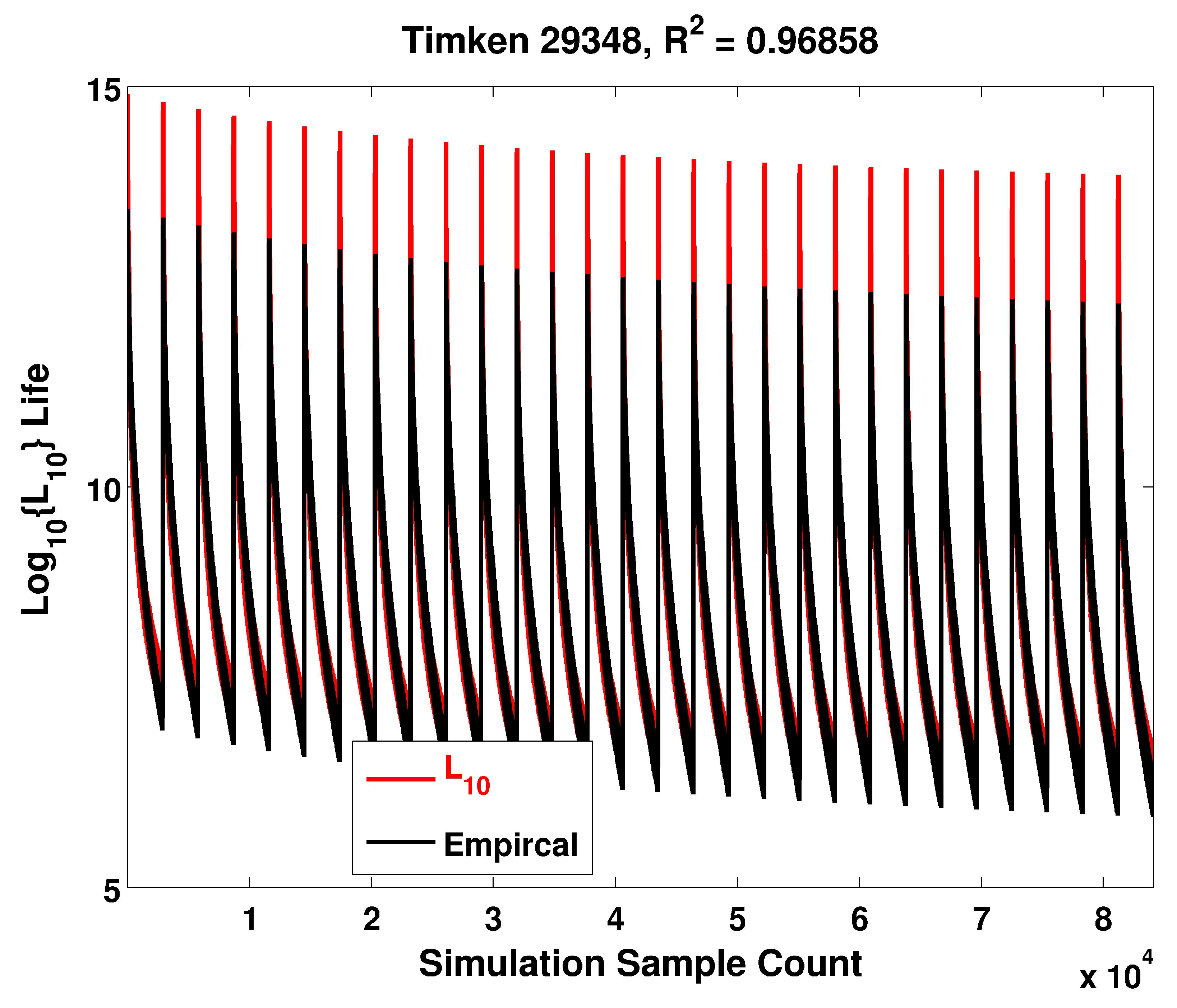
Figure 1. Calculated values of the L 10 life for the Timken 29348 roller bearing, utilizing theoretical Equation (25) and empirical Equation (1), all for a parametric series of loads, speeds, and lubricant temperatures. The data are placed in the order the parametric sample was conducted on the X-axis. The parametric study was conducted for a temperature ranging between 20 C and 300 C (112.2355 cSt to 1.0648 cSt), in increments of 10 C; an equivalent axial load of 1–100% (in 1% increments) of the 2040 kN dynamic load C a 1 ; and a bearing speed of 1000–15,000 RPM, in increments of 500 RPM.
Lubricants 07 00048 g001
Figure 2. Coefficients of Equation (25), for the 52 different Timken model bearings tabulated in Table 1.
Lubricants 07 00048 g002
Figure 3. The coefficient of determination R 2 between the calculated values of L 10 found with Equation (26), as compared to Timken’s empirical Equation (1), for the 52 different Timken model bearings tabulated in Table 1.
Lubricants 07 00048 g003
Table 1. Dimensions of Timken Spherical Roller Bearings, used in the parametric study described in Section 5. The average radius of the roller race R R (m) is the half the average of variables d b , H, E, and D, where R R = d b + H + E + D 8 .
Modeld (mm) C a 1 (kN) d b (mm)H (mm)E (mm)D (mm)
1294189082098.9148137190
229320100462108.1141134170
3294201001020108.8164151210
429322110604118.6157149190
5294221101200120.3180167230
629324120768128.5172163210
7294241201390131.6197182250
829326130852140.3186177225
9294261301600142.4213197270
1029328140970148.9199188240
11294281401640152.8223207280
1229330150993159.5209198250
13294301501860163.5238222300
14293321601190170.5225213270
15294321602100175255237320
16293341701230179.2235223280
17294341702380184.8270251340
18293361801430190.7251238300
19294361802660197.6286267360
20293381901620202.2268253320
21294381903040205.5303281380
22293402001880213.3284269340
23294402003210217317295400
24293442201950231.6303288360
25294442203350237.8339317420
26293482402040251.9323308380
27294482403410259360338440
28293522602580275.7356340420
29294522604160279.2391367480
30293562802580296.8376360440
31294562804920300.6423397520
32293603003150315.6407388480
33294603004990321.1443418540
34293643202830333.3427407500
35294643205155320469444580
36293683403120365.8463443540
37294683405922340500473620
38293723603632360476457560
39294723605440360528498640
40293763804295380507486600
41294763806493380546.1518670
42293804003850400534510620
43294804007333400577.1547710
44292844202682420513.1498580
45293844204040420561537650
46294844206780420608576730
47293884404530440585561680
48294884408606440635602780
49293924604820460614589710
50294924608120460666631800
51293964804820480635610730
52294964809320480700662850