1. Introduction
Nature shows examples of how periodic and self-organized surface structures decrease the coefficient of friction (CoF), for example, the skin of a snake, pangolin, and other animals. Such examples inspired surface engineering to generate surfaces with low CoF. Bearing in mind the processing time, which is requested by the different kinds of lithography, LIPSS-based process can be a potentially strong candidate for improving tribological performances. The mutual configurations of micro-and-nanostructures can improve tribological properties by guiding wear particles along the direction of the grooves or by inducing the particles rolling between them [
1].
Material processing by lasers with a pulse duration in the femtosecond range (10
−15 s) has recently drawn a lot of attention due to nonthermal ablation mechanisms [
2]. This characteristic makes this class of laser particularly appealing in material treatments, related to the absence of heat-induced material damage on dielectric, semiconductors, and metallic material [
3]. Femtosecond pulses have also been exploited to induce periodic surface structures known as laser-induced periodic surface structures (LIPSS), firstly observed in 1965 [
4]. As it is commonly accepted, LIPSS are divided into 2 groups: Low Frequency LIPSS, where period of structures is around laser wavelength, and High Frequency LIPSS, where period of structures by order of magnitude less than laser wavelength. Further, in paper Low Frequency LIPSS will be noted like LIPSS, while High Frequence LIPSS will be indicated as it is. LIPSS are already used and have a potential to be applied in numerous fields, including improving adhesion [
5], wettability [
6], surface colorization [
7], better proliferation and adhesion of tissue cells [
8], and others.
The shortcomings to apply LIPSS for tribology were recognized by Yu and Lu in 1999 [
9]. They obtained microstructures with a nanosecond excimer laser and demonstrated the improvement of tribological characteristics in comparison to a non-treated surface. Furthermore, Honda at al. [
10] used femtosecond laser-generated LIPSS on diamond-like carbon (DLC) and tested friction properties with an atomic-force microscope. This test showed a reduction of friction on the film with LIPSS compared with the untreated ones. Yasumaru et al. [
11] also tested DLC, additionally coated with a thin layer of MoS
2, showing how to decrease and increase CoF. Using different beam scanning strategies, they generated LIPSS and demonstrated a CoF reduction compared to a flat surface. The study in [
12] showed a CoF decrease even without lubricant in a pin-on-disc configuration on TiC-coated steel surface. The first tribological tests on LIPSS-textured semiconductors were made by Eichstadt et al. in [
13], where an increase of the CoF was observed in both lubricated and non-lubricated conditions.
The tribological performances were investigated on large LIPSS-treated area of 100Cr6 stainless steel, high toughness bearing steel X30CrMoN15, pure titanium and titanium alloy (Ti6Al4V) by using a ball-on-disc configuration under paraffin and engine oil as lubricants in [
14] and [
15]. No effect was measured on CoF for LIPSS-treated samples tested with both the mentioned lubricants. While a significant reduction of CoF and wear for Ti and Ti6Al4V was shown with engine oil in the case of ripples oriented perpendicularly to the sliding motion, no beneficial influence appeared with paraffin oil. It should be outlined that these were the first experiments demonstrating the dependence of the CoF by LIPSS orientation, while the mechanisms relating to the influence of nanometric structures on the CoF have not been correctly explained.
The first research on wear and tribological performances for High Spatial LIPSS (HSFL) was made by Bonse et al. [
16], where the large Titanium samples were covered by LIPSS and tested with paraffin and engine oil as lubricants. The related tribological analysis did not demonstrate the effects of HSFL on CoF, concluding that the depth of LIPSS played a crucial role in friction behavior.
In [
17], the authors investigated the effects of LIPSS on AISI 316, obtaining a sensible CoF reduction on both dry and lubricated conditions. Another important tribological quantity is the Stribeck curve. In fact, in a lubricated contact, the CoF is not a univocal quantity independent on the load and velocity, as in the case of dry contacts. In fact, in the presence of lubricants, the CoF is a function of the Stribeck number, given by the relation:
where ƞ is the viscosity of the oil, v is the sliding velocity, and L is the applied load.
The typical Stribeck curve is divided into three regimes, the boundary lubrication (BL), the mixed lubrication (ML), and the elastohydrodynamic (EH) regimes. At low Stribeck number, the two counterparts are completely in contact, and a small amount of lubricant is present between them; this situation represents the BL regime. This regime is characterized by high CoF and high wear. Increasing the Stribeck number increases the oil thickness, leading to a decrease in the CoF down to its minimum; this situation represents the ML regime. Increasing the Stribeck number further leads to the transition into the EH regime, where the lubricant thickness is continuous, and the friction is ruled by the viscosity characteristics of the oil. In this last regime, the CoF slightly increases with the Stribeck parameter due to viscous effects. The building of the Stribeck curve enables to define the three different Stribeck regimes as a function of the load and the sliding velocity.
One of the main drawbacks of the cited works is that, in case of linear textures, only reciprocating friction can be investigated, with the known issues about control of speed and, in the case of lubricant, the fluid dynamic conditions. In the present paper, the tribological properties of LIPSS-textured stainless steel samples were investigated, using advanced techniques to generate highly regular LIPSS (HR-LIPSS) [
18]. The textures were obtained with radial symmetry, permitting to investigate the Stribeck curve in a pin-on-disc configuration, with a fixed orientation of the LIPSS texture with respect to the sliding direction. In particular, we were interested in surface texturing as a tool to improve the tribological performance of tribo-pairs in BL and ML regimes, the most critical regimes in a mechanical device. To the author’s knowledge, this approach was never applied in the aforementioned literature.
2. Materials and Methods
2.1. Laser Set-Up
Periodic radial straight grooves patterned with LIPSS were generated on 30 mm diameter discs made of X5CrNi1810 steel. The discs were previously lapped to have a 30 nm average roughness (Root Mean Square).
In the experiment, Yb:KGW a chirped-pulse application laser system (model PHAROS 20W from Light Conversions Ltd. was used. Optical pulses (central wavelength 1030 nm, pulse width 213 fs, repetition rate 600 kHz) were forwarded to a galvanometric scanning head (Cambridge Technology). Alignment of linearly polarized laser light was controlled by a half-wave plate. The surface treatment was done in air at room temperature by scanning a laser beam across the sample surface. The laser beam was focused by an F-theta lens with a focal length of 56 mm that produced an approximate diameter of the irradiation spot of 10.6 microns (1/e2 of peak intensity) on the sample. The transmittance of the focusing system was measured independently prior to the experiments and was found to be 80% at the laser wavelength. With this data, a peak fluence of 0.51 J/cm2 was estimated on the surface.
Figure 1 shows the strategy of laser treatment. For the scanning approach, 5 mm long scanlines were formed in the radial direction by moving the laser spot with the galvanometric scanner at a scanning speed
equal to 3 m/s, while rotational motorized stage with circumferential speed ω of 1.45–2.5 rad/s generated circular patterned tracks with 4 microns of interline spacing. The polarization plane was set-up to uniformly orient LIPSS in the circumferential directions.
2.2. Focused Ion Beam (FIB) Analysis
Each disc was patterned to have three concentric textured areas with different radius. In each circle, two tribo-tests were performed at most. Similarly, the tribo-tests on the flat surface were made in the textured-free area of the discs.
FIB was employed to explore local properties, allowing to remove and observe trenches of the surface without introducing relevant additional damage, and thus to detect sub-surface micro-structure (buried cracking, defects, contaminations, etc.) [
19,
20,
21]. Such characterization was performed by using a dual-beam system (FEI StrataTM DB235), combining a high-resolution FIB column equipped with a Ga Liquid Metal Ion Source (LMIS) and a Secondary Electron Microscope (SEM) column equipped with Schottky Field Emission Gun (SFEG) electron source. We obtained perpendicular “micro-cross sections” of samples using a FIB (e-beam = 30 KeV) as a micro-machining miller, setting a 1 nA ion beam current for the first rough trench, and a 300 pA ion beam current for final polishing. Thus, a step-by-step milling procedure was carried out to extract tranches of surface: preliminarily, to prevent the topmost material from mechanical intermixing upon contact with energetic ions [
22], the surface sample was capped by a thin platinum layer (1 µm thickness). A Pt-shield had been grown, starting from a gas precursor and using a 300 pA ion beam current that assisted the local deposition. Finally, by tilting the sample holder, we obtained images of discovered walls collecting secondary electrons generated by electron column as a primary beam; in particular, we used electron column as a primary beam for non-destructive secondary electron analysis (e-beam = 15 KeV).
2.3. Tribology Test
The tribological tests were performed in a dedicated chamber filled with 20 mL commercial motor oil Shell Elix Synthetic 5w-40. The tests consisted of building the Stribeck curves of the textured and untextured surfaces, the last one used as a reference.
To check the load range that has to be applied to fall in BL and ML regimes, some preliminary tests were performed at different loads and velocity, not reported in the manuscript. We realized that, when falling in the BL regime, wear was very severe, and the texture was completely destroyed. To avoid this, we decided to focus on ML regime, assuming that the effect in the BL regime was similar.
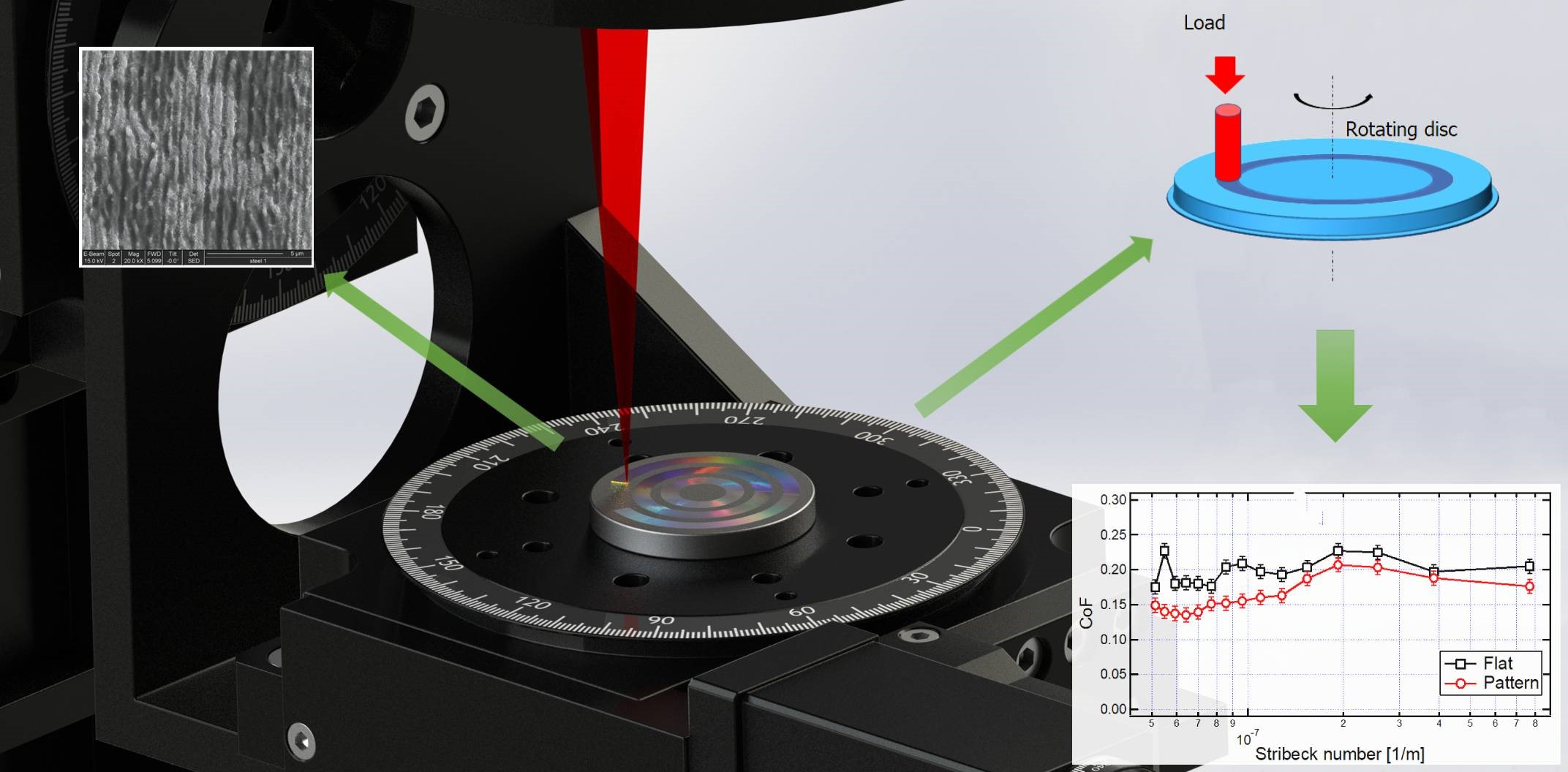
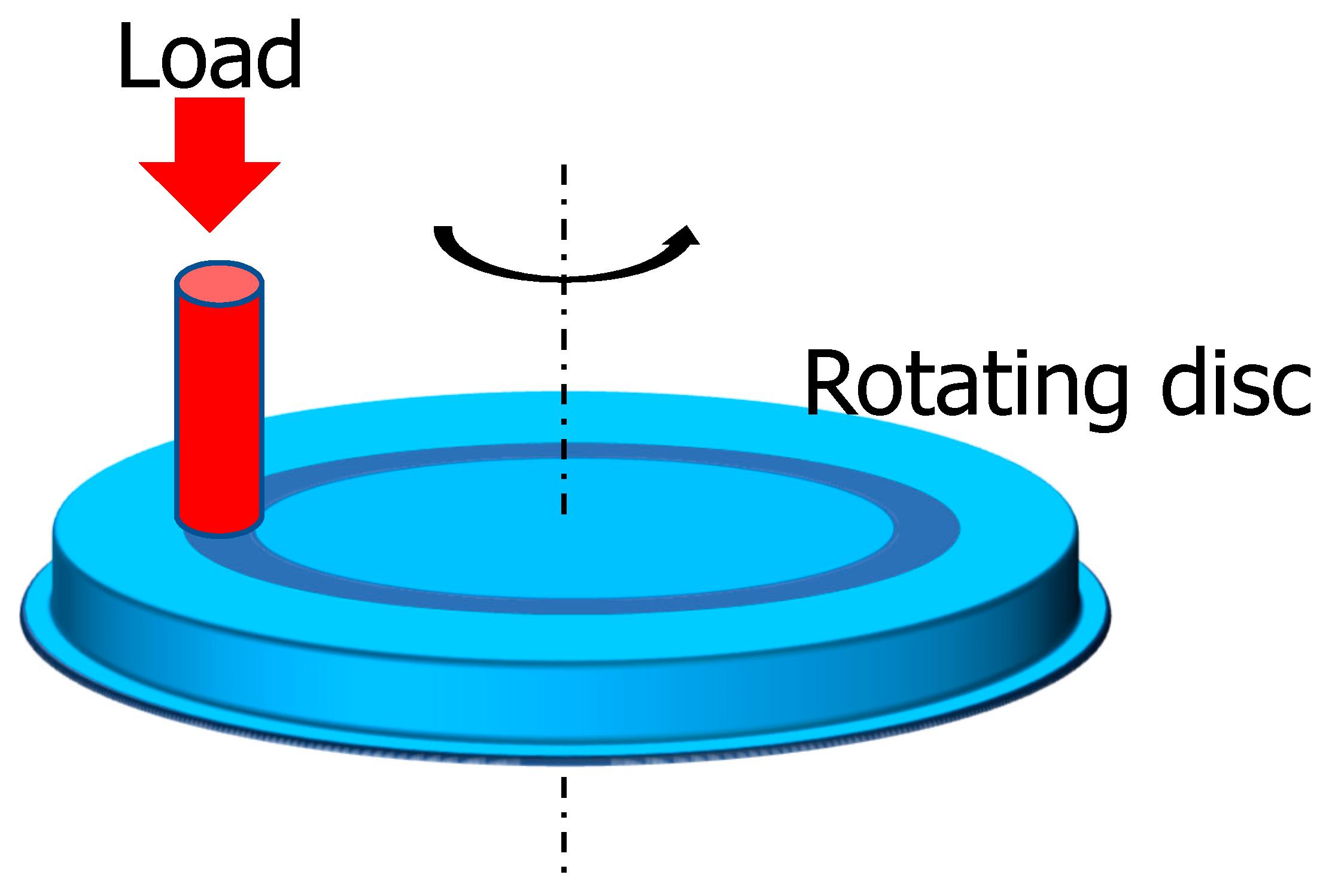
In the calculation of the Stribeck parameter, the value of the oil viscosity was set to 1 Pa·s for simplicity, considering that all the tests were performed with the same oil. To change the Stribeck number, two strategies can be applied, namely changing the load or changing the sliding velocity. In the present study, the load was varied from 0.5 to 7.5 N in steps of 0.5 N, keeping the sliding velocity constant at 7 mm/s. The sliding configuration was pin-on-disc, where a flat pin of 2 mm diameter was loaded on a rotating disc (
Figure 2). The range of the track radius was between 8.5 and 14 mm. The pins are made of 100Cr6 steel. Each test was repeated at least 3 times, and the results were averaged, leading to the Stribeck curves shown in the Results and Discussions section. The oil was replaced every 3 tests with the new one.
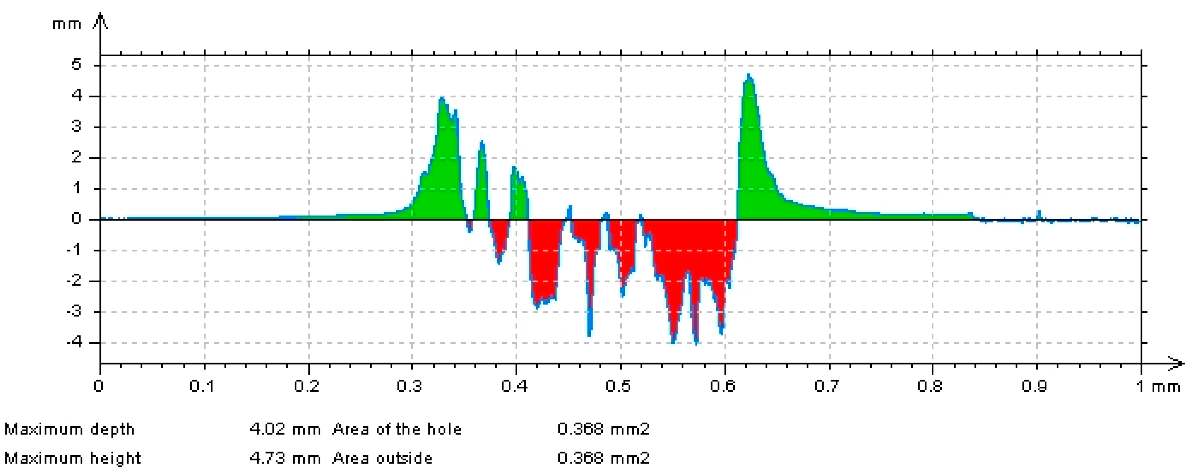
After the Stribeck tests, the line cross-sections of the related wear tracks were measured by a stylus profilometer, to quantify the wear. In
Figure 3, a wear-track profile is reported, by way of example. It is possible to identify the worn material (red area) and the pile-up (green area). For each wear track, 4 profiles were acquired, corresponding to the 4 cardinal points of the circular track. The corresponding wear areas were averaged, enabling the calculation of the average wear volume.
3. Results and Discussion
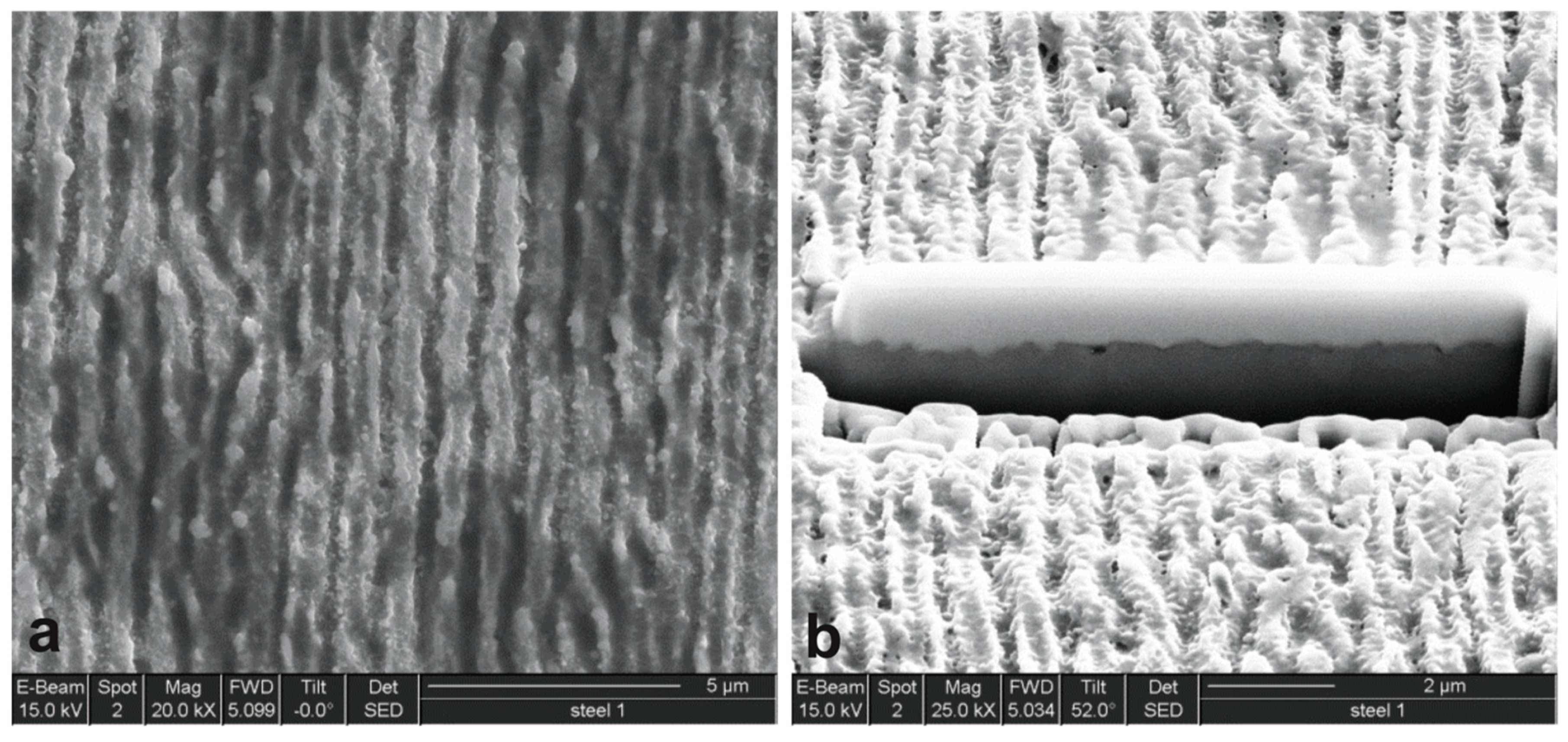
Figure 4a,b show the top view and the cross-section, respectively, of LIPSS-treated surface of the steel, imaged by SEM.
Figure 4a shows the typical morphology of the related texture, characterized by the periodic alternation of parallel grooves and valleys, separated by about 600 nm. This morphology was uniformly distributed all over the processed surface, proving the accuracy and reproducibility of the method. The observation of the texture at a 52° tilt angle with respect to the normal revealed a second-order pattern, composed of parallel straight nanostructures perpendicular to the primary-order grooves (
Figure 4b).
In the FIB cross-section, the bright Pt protection layer was visible on top of the section. Just under the Pt layer, the height variation of the texture was evident. The peak-to-valley distance was measured for a large number of structures, resulting in between 120 and 300 nm. The sub-surface portion of the texture appeared uniform and compact, with no presence of void or crack, indicating that the laser effect was localized in the very outermost part of the material.
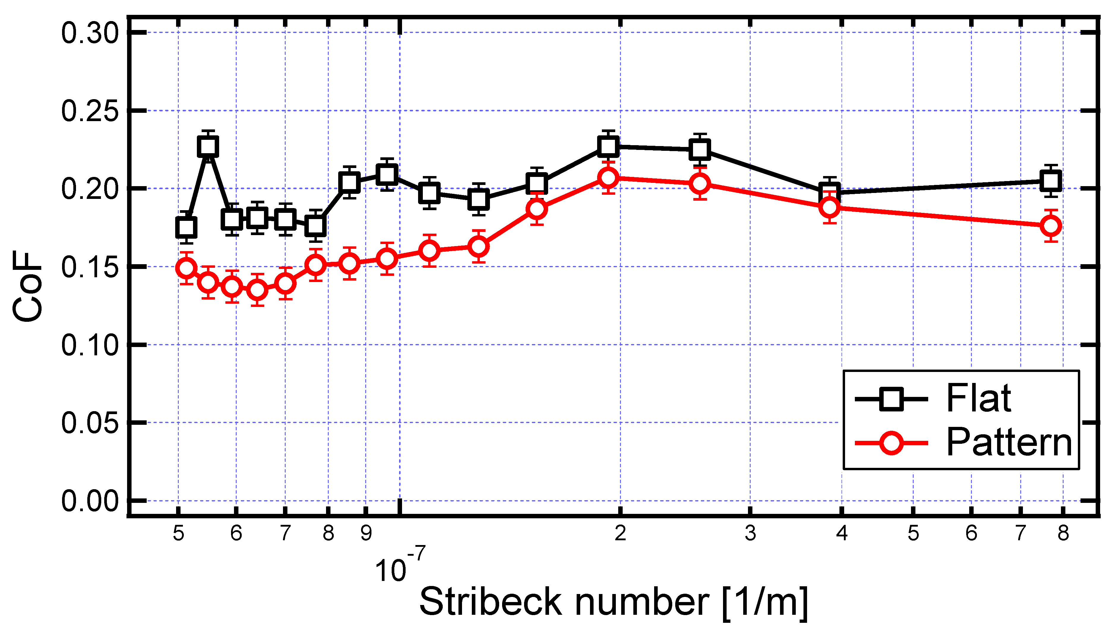
In
Figure 5, the results of the tribological investigation were reported, for the patterned surface and the unpatterned flat one, used as a reference. The test was referred to one pin, but similar results were found for other similar pins (not shown). The curves represented the CoF variation in ML regime. As evident from the curves, at the lowest Stribeck number, the system was in the minimum of the ML regime and progressively increased towards the EH region (not evident from the graph). All over the investigated range, the CoF on the patterned surface was sensibly lower than on the unpatterned one; the CoF reduction went from a minimum of 10% for 4–8 × 10
−7 m
−1, to a maximum of 25% for 5–9 × 10
−7 m
−1. This was a very important result because the most effective reduction appeared in the most severe condition of the exploited range (namely at low Stribeck number). As already reported in many other studies on surface texturing, this could be ascribed to the reservoir effect of the grooves, which release lubricant even when the two counterparts are in contact, maintaining effective lubrication [
23,
24,
25].
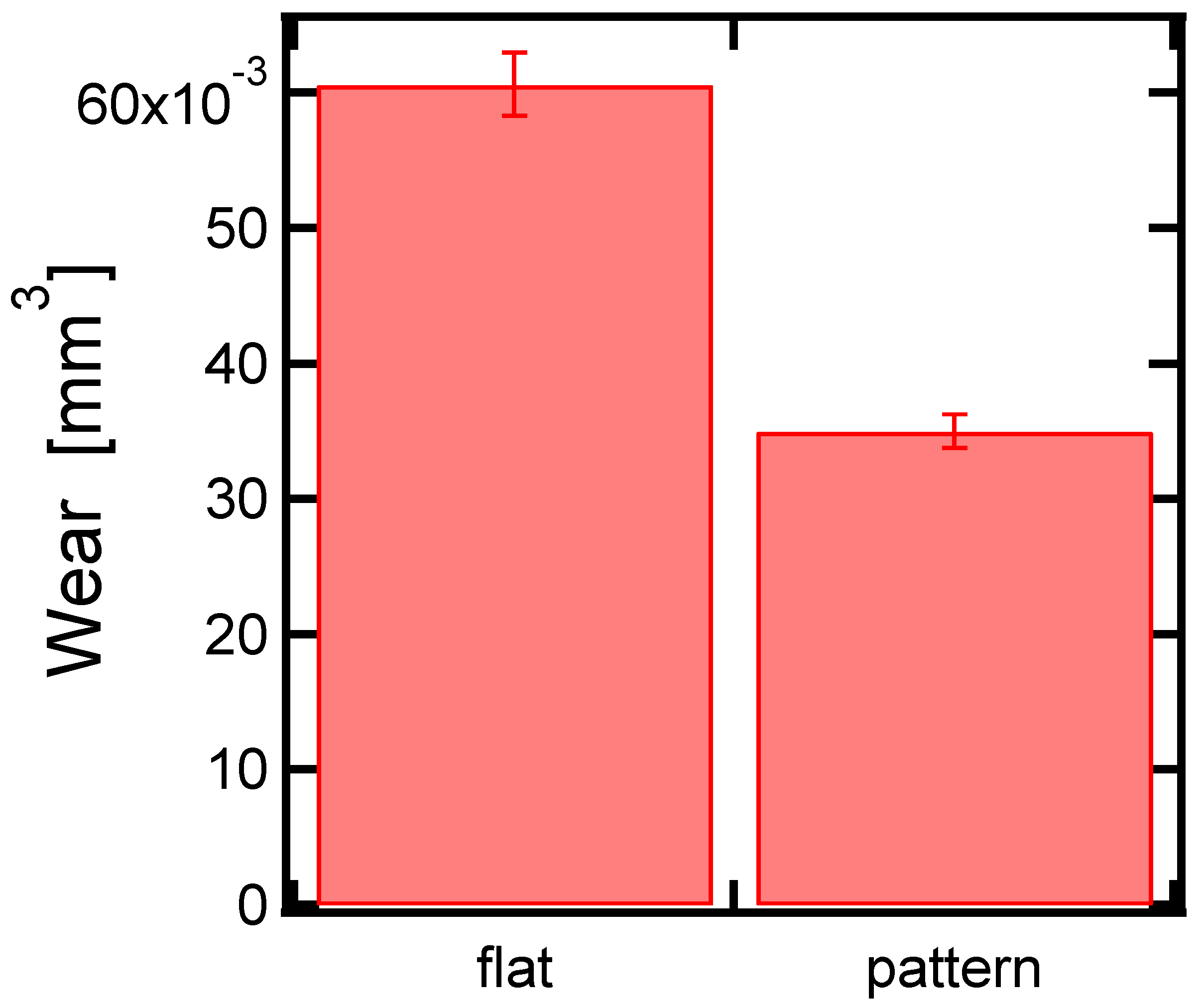
The effect of LIPSS has been studied in terms of wear reduction as well. As evident from
Figure 6, the wear of the disc during the Stribeck tests was less pronounced in the case of the textured surface, leading to a wear reduction of about 65%. This was probably related to the role played by the grooves as debris pocket, which limits the amount of particulates all over the interface, and so their effect as the abrasive body.


