Abstract
Wear-related complications remain a major issue after unicompartmental arthroplasty. We used a computational model to predict knee wear generated in vitro under diverse conditions. Inverse finite element analysis of 2 different total knee arthroplasty designs was used to determine wear factors of standard and highly crosslinked polyethylene by matching predicted wear rates to measured wear rates. The computed wear factor was used to predict wear in unicompartmental components. The articular surface design and kinematic conditions of the unicompartmental and tricompartmental designs were different. Predicted wear rate (1.77 mg/million cycles) was very close to experimental wear rate (1.84 mg/million cycles) after testing in an AMTI knee wear simulator. Finite element analysis can predict experimental wear and may reduce the cost and time of preclinical testing.
1. Introduction
Bearing wear has been a major reasons for complications after knee arthroplasty [1,2]. Although several biomaterials have been introduced to reduce wear in other joints, polyethylene continues to be the most popular material for the insert bearing in knee arthroplasty. Advances in crosslinking of polyethylene have been successful in dramatically reducing wear rates and osteolysis in hip arthroplasty [3]. The clinical success of crosslinked polyethylene in hip arthroplasty has led to its introduction in knee arthroplasty [4]. However, the inherent differences in hip and knee implant designs and differences in loading and kinematics do not permit direct extrapolation of the results of hip wear testing to knee wear testing.
Total knee arthroplasty (TKA) has an overall high success rate in terms of implant survival. Revision for wear is no longer as common as revision for infection, instability, and stiffness [5,6]. However, it is difficult to justify tricompartmental arthroplasty in young or middle-aged patients with unicompartmental disease. These patients are often more athletic and expect better function than the typical patient with tricompartmental disease. Long-term outcomes of high tibial osteotomy have not been consistent with survivorship that decreases to 75% at 10 years and 65% at 15 years [7,8]. Unicompartmental knee replacement can be an attractive alternative for this patient population [7,9,10].
Unicompartmental arthroplasty (UKA) preserves the rest of the joint and has been shown to better approximate normal knee kinematics than TKA [11]. However, survivorship after UKA is often lower than that in TKA [12,13]. Wear and polyethylene damage continue to be important factors affecting outcomes and have been implicated in up to 22% of revision surgeries after unicompartmental knee arthroplasty [14].
Knee wear simulation in vitro requires expensive equipment and several months of testing. Computational models of knee wear have been used to reproduce experimental wear. These wear factors are typically based on Archard’s law, which assumes that wear is a function of local contact pressure and sliding distance [15]. Simulations of knee wear have been reported with a constant wear factor (first-generation Archard wear factors), with wear factors that vary by a function of the cross-shear (second-generation Archard wear factors), and by treating wear as a function of contact area (and sliding distance) rather than contact stress [16,17,18,19]. Common wear factors are those derived from pin-on-disk wear experiments. However, wear factors derived from pin-on-disk experiments, even those that vary by a function of the cross-shear, have not been shown to be accurate in predicting experimental or clinical wear rates [20]. In addition, very few of these models’ predictions have been validated under diverse conditions [16,18].
We first used an inverse FEA approach to derive an “apparent” wear factor from our experimental knee wear simulations. The inverse FEA approach adjusts the wear factor used in the model until the predicted wear rate matches the experimental wear rate. Our objective was to determine if a wear factor computed for a specific combination of TKA bearing materials (polyethylene and cobalt-chrome (CoCr) alloy) and lubrication conditions could be used to predict wear in a different design (UKA) with the same materials but under different kinematic and loading conditions. We therefore used the FEA model to predict wear in UKA (using the wear factor obtained for TKA wear). The only change we made to the model was in the implant design (TKA to UKA) and in the kinematics and loading of the knee. The material properties of polyethylene, the algorithm to compute wear, and the wear factor were the same for both TKA and UKA models. Our objective was to predict UKA wear that closely matched experimental wear measurements and support the robustness of our model.
2. Materials and Methods
2.1. Experimental Wear Simulation of Tricompartmental Design
Gravimetric wear rates were obtained from previously reported experimental wear simulations of standard crosslinked polyethylene (Sigma® CR, DePuy, Warsaw, IN) and highly crosslinked polyethylene (Triathlon CR X3, Stryker, Mahwah, NJ, USA) [21,22]. We selected these 2 experimental studies based on differences in design, in bearing material, and in loading kinematic conditions. A computer model that could replicate both wear simulator studies would likely be more robust. One group (n = 3), comprised of moderately conforming cruciate-retaining inserts (Sigma® Curved, DePuy, Warsaw, IN, USA) subjected to 40 kGy sterilization irradiation (standard crosslinked). The second group (n = 3) consisted of moderately conforming cruciate-retaining inserts (Triathlon TKA) with UHMWPE inserts manufactured from compression molded GUR 1020 UHMWPE that were subjected to gamma irradiation to 30 kGy followed by an annealing process and then repeated 2 more times for a total dose of 90 kGy (highly crosslinked, X3®, Stryker). Femoral and tibial components for both groups were manufactured of CoCr alloy. Three implants from each of the 2 groups were tested on a 6-station displacement-controlled knee wear simulator (AMTI, Watertown, MA, USA).
Lubrication was provided by bovine serum (25%) supplemented with EDTA and sodium azide. Total protein concentration of the batch of bovine serum was 8.5 g/dL, with the albumin component being 3.2 g/dL (data provided by the supplier, Sigma-Aldrich, St. Louis, MO, USA). For the standard crosslinked tricompartmental design, the ISO-recommended wear testing protocol for displacement controlled knee wear simulators was used [23]. For the highly crosslinked tricompartmental design a more aggressive protocol was used, which involved a medial to lateral axial load distribution of 70:30 and a tibial axial rotation offset to simulate malaligned tibial components. Wear was monitored by visual inspection and by measuring weight loss at approximately 500,000 cycle intervals for a total of 5 million cycles. To correct for fluid absorption, implants of each group (n = 3) were soaked in bovine serum lubricant for the duration of the study and were subjected to the same dehydration and weighing protocol.
2.2. Computational Determination of Wear Factor
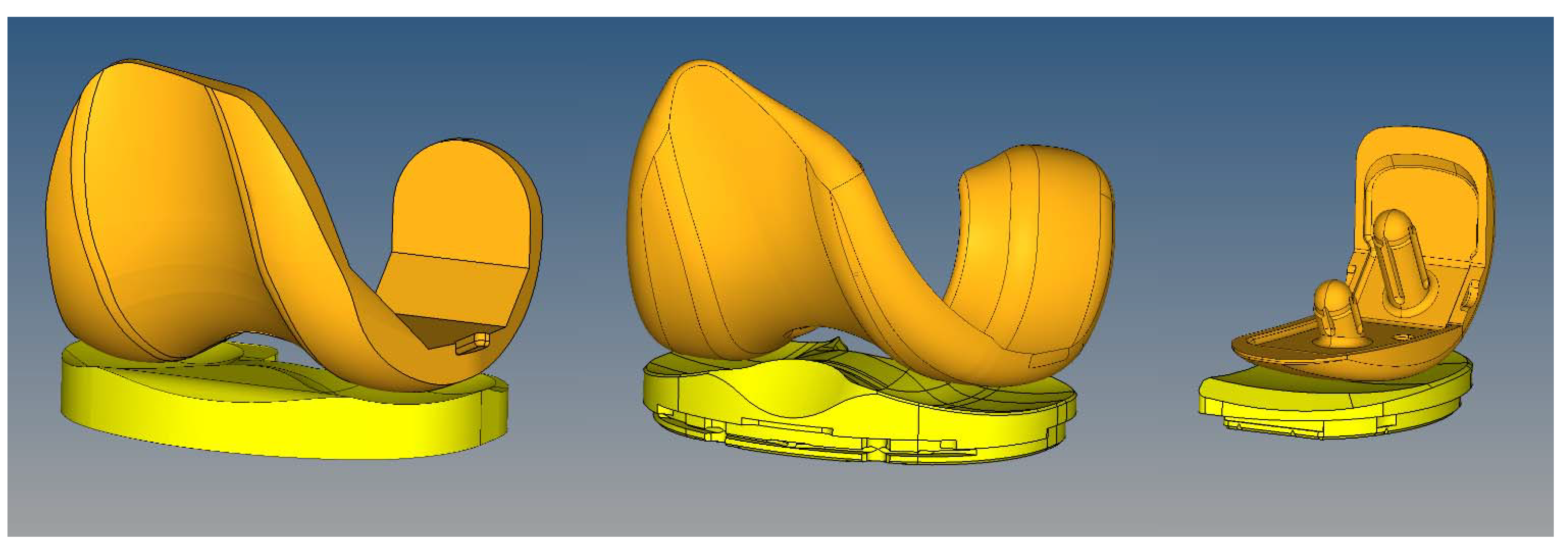
A computational model of the boundary conditions of the AMTI wear-testing machine was constructed in MSC.MARC (MSC Software, Santa Ana, CA, USA). Loading and motion conditions used in each of the experimental studies were replicated in the computer simulation. The axial load was force controlled, while flexion, anterior-posterior translation, and internal-external rotation were displacement controlled. The tibial tray was free to translate in the mediolateral direction and to rotate in varus-valgus (similar to the experimental protocol). CAD models of the implants (Figure 1) were meshed using HyperMesh (Altair Engineering, Inc., Troy, MI, USA). The polyethylene inserts were meshed with hexahedral element. Optimum mesh density was calculated in 2 stages. Predicted peak contact stresses and contact area in a simplified model of a spherical rigid body indenter with a radius of 14 mm (simulating a femoral condyle) contacting a flat “insert” (50 × 50 × 50 mm) with a linear elastic modulus of 700 MPa was compared to an analytic Hertzian contact solution [24]. Multiple loads (range, 100–1000 N) generating peak contact stresses of up to 70 MPa were simulated. Convergence of contact area measurement and peak contact stresses within 3% of the analytical solution was achieved with a mesh density using elements with a mean edge length of 1.5 mm. Next, convergence of peak contact stresses for the FEA model using the corresponding prosthetic component geometry were also obtained with a mean edge length of 1.5 mm (less than 1% change in peak contact stresses between mean element sizes of 1.5 mm and 1.0 mm). The inserts were modeled with a Young’s Modulus of 700 MPa and Poisson’s ratio of 0.43. While we have implemented nonlinear viscoelastic and elastoplastic material models in previous studies, we did not detect a significant difference in wear rates between linear and nonlinear material models [25,26]. The femoral and tibial metal components were simulated as rigid bodies. Contact was simulated between the femoral and the insert articular surfaces with a coefficient of friction of 0.2.

Figure 1.
Finite element models were generated to simulate the experimental wear tests. Left: Sigma PFC standard crosslinked tricompartmental design; Middle: Stryker Triathlon X3 highly crosslinked tricompartmental design; Right: Stryker Triathlon PKR highly crosslinked design.
Figure 1.
Finite element models were generated to simulate the experimental wear tests. Left: Sigma PFC standard crosslinked tricompartmental design; Middle: Stryker Triathlon X3 highly crosslinked tricompartmental design; Right: Stryker Triathlon PKR highly crosslinked design.
Contact area, contact pressure, and sliding distance were computed. Wear was predicted by using the Archard’s classic law for mild wear.
Each cycle was divided into 100 increments and wear was computed for each increment and summed over the entire cycle. The surface nodes affected by wear were moved in a direction normal to the articular surface based on the computed material loss at the end of every increment. The MSC.MARC solver adaptively adjusted interior nodes to maintain element quality. The simulation was then repeated in a step-wise manner and the wear was multiplied by the size of each step (50,000 cycles per step) to compute the total wear at the end of 5 million cycles. This update interval was shorter than those used in previously published FEA studies of TKA wear: 100,000 and 200,000 cycles [16]; 500,000 cycles [17]. For comparison with experimental data, computed volumetric wear was converted to gravimetric wear using polyethylene density of 0.97 mm3/mg. The wear factors for the standard and highly crosslinked polyethylene were then determined by minimizing the difference between predicted wear and experimental wear rate using a global optimization tool (Isight, Dassault Systèmes, Providence, RI, USA). The wear factor obtained for highly crosslinked polyethylene was used to predict wear in Triathlon X3 PKR (partial knee replacement) components. To assess differences in kinematic patterns between experimental wear tests we also calculated crossing intensity using the method reported by Hamilton et al. [27].
2.3. Experimental Wear Simulation of Unicompartmental Design
PKR (unicompartmental) components were experimentally tested on the AMTI knee wear simulator. The implant materials (CoCr alloy and X3 polyethylene) and serum lubricant conditions were the same. However, the PKR is a unicompartmental design and the loading and kinematic conditions were significantly different from the tricompartmental wear simulation.
PKR inserts were mounted on top of the tibial tray and fixed by a press-fit mechanism supplemented with threaded bolts that allowed the inserts to be removed for cleaning and weighing without damaging the polyethylene. All components were mounted medial to the center of axial rotation of the knee station to simulate a medial compartmental knee arthroplasty.
Lubrication was the same as for the tricompartmental wear simulation. The ISO-recommended wear testing protocol for displacement controlled knee wear simulators was used. Since there was no lateral compartment, the entire axial load (representing 60% of the medial compartmental load) was transmitted through the unicompartmental components. Wear was monitored as described for the tricompartmental design. To correct for fluid absorption, additional inserts were soaked in the bovine serum lubricant for the duration of the study and were subjected to the same dehydration and weighing protocol.
3. Results
Wear factors generated for standard crosslinked and highly crosslinked polyethylene tricompartmental inserts are listed in Table 1. The simulated wear area visually approximated the experimental wear scars (Figure 2). Wear rates predicted by the finite element model for the PKR design were within 5% of those measured experimentally (Figure 3).
We analyzed the relative contribution of contact area, contact pressure (Figure 4), and sliding distance (Table 2). Instantaneous peak contact stresses averaged over the entire gait cycle and were 18.1 MPa for the standard crosslinked tricompartmental design, 26.8 MPa for the highly crosslinked tricompartmental design, and 31.1 MPa for the highly crosslinked PKR design (Figure 4).
Linear wear penetration was measured as the maximum depth of wear in the vertical direction and was computed for the standard crosslinked tricompartmental design, the highly crosslinked tricompartmental design, and the highly crosslinked PKR design. For comparison with clinical retrieval studies, the distribution of linear penetration was also calculated in the medial and lateral compartments (Table 3). Wear occurring during the stance phase was compared to that occurring during the swing phase and was expressed as a percentage of total wear (Table 4).

Table 1.
Computed Wear Coefficients (mm3/N × mm).
| Standard Crosslinked PE | Highly Crosslinked PE |
|---|---|
| 1.70 × 10⁻¹⁰ | 5.24 × 10⁻¹¹ |
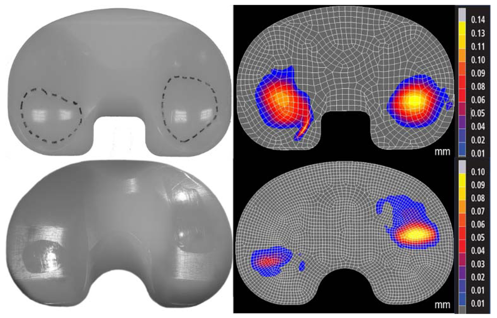
Figure 2.
Photographs of experimental wear scar (left) were compared to predicted wear depth contour maps (right, mm) in the standard (top) and highly (bottom) crosslinked polyethylene (Sigma and Triathlon designs, respectively). The differences in location of the wear scars were due to the differences in kinematics between the two designs.
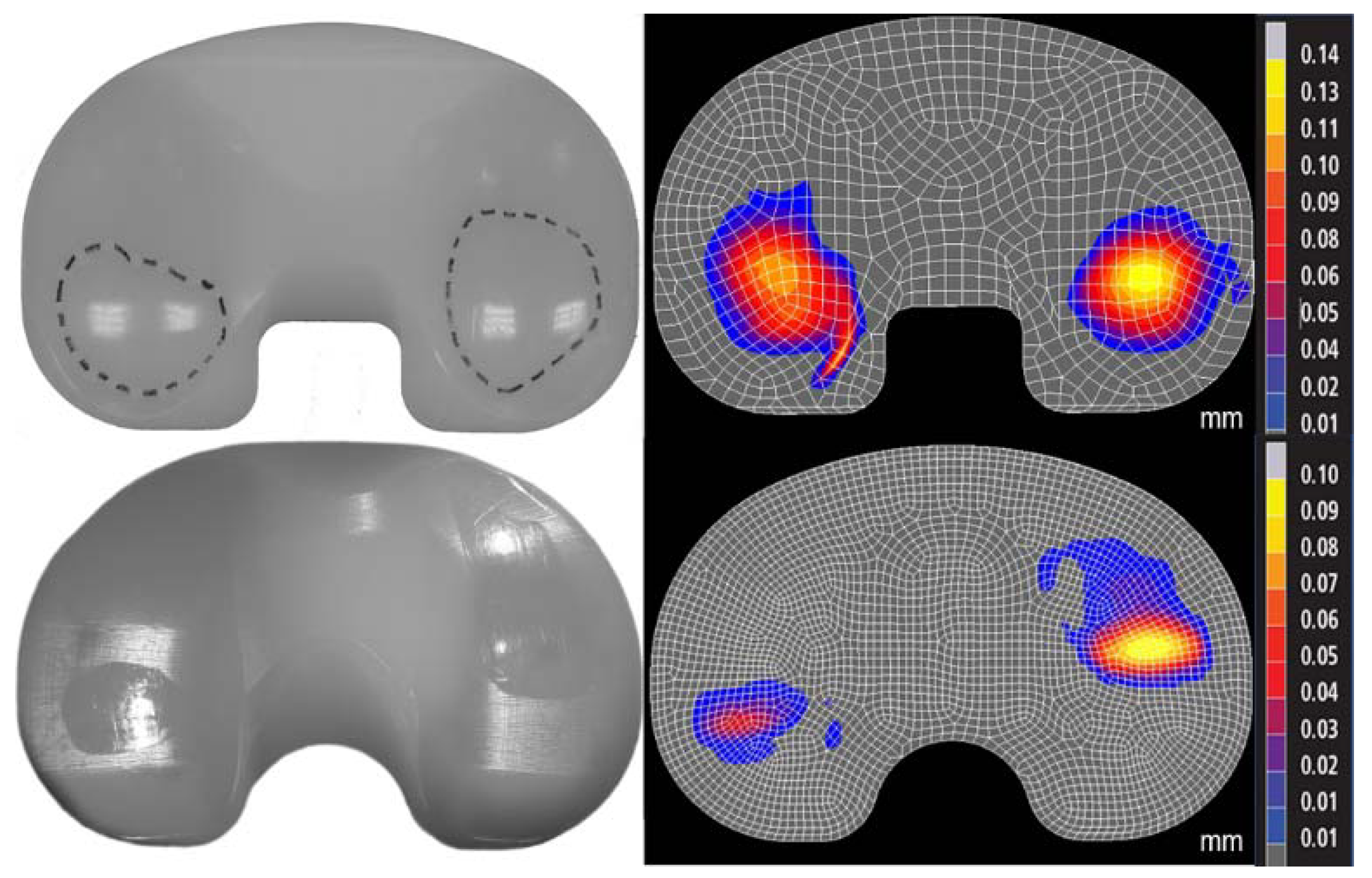
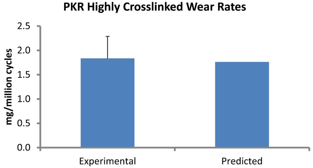
Figure 3.
Computational predictions of wear rate (mg/million cycles) in the PKR design were very close to experimental measurements.
Figure 3.
Computational predictions of wear rate (mg/million cycles) in the PKR design were very close to experimental measurements.

Table 2.
Relative sliding distance (mm/cycle).
| Triathlon TKR | Triathlon PKR |
|---|---|
| 57.6 | 39.9 |
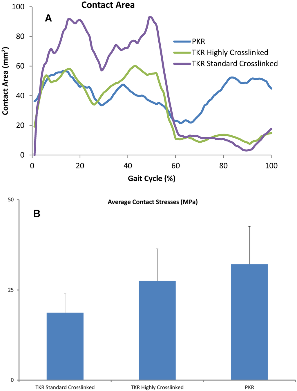
Figure 4.
(A) Contact areas computed for each condition were plotted over the entire gait cycle. (B) Contact pressures were computed for all three designs and averaged across each cycle. Error bars denote standard deviation of area or peak contact stress over each cycle.
Figure 4.
(A) Contact areas computed for each condition were plotted over the entire gait cycle. (B) Contact pressures were computed for all three designs and averaged across each cycle. Error bars denote standard deviation of area or peak contact stress over each cycle.

Table 3.
Linear penetration rates (mm/million cycles).
| Polyethylene type | M:L Load Distribution | Medial Penetration | Lateral Penetration |
|---|---|---|---|
| Highly Crosslinked TKA | 70:30 | 0.025 | 0.018 |
| Standard Crosslinked TKA | 60:40 | 0.045 | 0.039 |
| Standard Crosslinked TKA | 68:32 | 0.054 | 0.029 |
| Highly Crosslinked PKR | 60:40 | 0.019 |
Table 4.
Wear in stance and swing phase (% of total wear).
| Phase | Triathlon TKR | Triathlon PKR |
|---|---|---|
| Stance | 56 | 62 |
| Swing | 44 | 38 |
4. Discussion
Measuring wear in vivo after knee arthroplasty is technically difficult. In vitro wear simulation has been validated as being reasonably predictive of clinical wear performance but requires expensive equipment and several months of test duration to complete the equivalent of five years of clinical performance [28]. We simulated wear rates under one set of implant design and kinematic conditions in a finite element model and used the model to predict wear in a different design under different kinematic conditions. Predicting wear under diverse conditions increased the validity of our model.
A finite element-based wear model generated the wear factor for crosslinked polyethylene (Triathlon X3) against the CoCr alloy using previously reported experimental wear measurements. The location of the wear scars on the experimentally tested inserts was visually congruent with the distribution of wear depth in the computer model. This wear factor was then used to predict wear for a unicompartmental design (Triathlon PKR) under significantly different loading and kinematic conditions. The model predicted wear rate (1.77 mg per million cycles) that was within 0.1 mg of the experimentally measured values (1.84 ± 0.45). We assessed the sensitivity of computed wear rate to the magnitude of wear factor and found that the wear rate changed by 0.18 mg/million cycles for each 10% difference in magnitude of wear factor. We also computed wear rates for two commonly reported constant wear factors: 2.64 × 10⁻¹⁰ and 1.07 × 10⁻⁹ mm3/N-mm, which yielded wear rates of 9.07 and 37.38 mg/million cycles, respectively.
Validated computer models make it feasible to isolate the effects of major factors thought to contribute to wear, such as the wear coefficient for the bearing material pair, contact area and pressure between articulating surfaces, and the relative sliding distance. The Sigma Curved design has a higher tibiofemoral conformity, which is reflected in the greater contact area and lower contact pressure. Nevertheless, the crosslinked polyethylene wore substantially less, which emphasized the importance of significantly low coefficient of wear.
While linear penetration depth and volumetric wear are somewhat correlated, these outcome measures are sensitive to different factors. Small contact areas with high contact stresses generate higher linear penetration than volumetric wear, while large contact areas with low contact stresses can increase volumetric wear with lower linear penetration. This distinction can be important since a tendency toward greater linear penetration is more likely to result in localized damage to the insert (or even wear through); while a tendency toward greater volumetric wear (with low linear penetration) is more likely to generate greater volume of wear debris and can result in an osteolytic reaction.
One advantage of finite element models is the ability to identify wear rates during different phases of the gait cycle (such as stance phase wear versus swing phase wear rates), which is virtually impossible with experimental wear measurements. As anticipated, the predicted average wear rate was higher during the stance phase of the gait cycle. However, the wear rate during the swing phase was surprisingly high: 38% and 44% of total wear for the highly crosslinked PKR and TKR, respectively (Table 4). The ISO standard for knee wear simulation recommends an axial load of 168 N during the swing phase [23]. We have measured loads in vivo averaging 0.3 times body weight [29]. Despite the substantially lower loads during the swing phase, predicted wear was not insignificant. Crossing intensity can vary during the stance and swing phases; we calculated that average crossing intensity during swing phase was greater by 0.024. Our model assumed an apparent wear factor representative of the “average” amount of cross-shear, therefore the fraction of wear during the swing phase was likely to be even higher that our prediction, which was due to the small increase in crossing intensity. Our analysis indicated this was a combination of greater sliding distance (due to the larger knee flexion arc during swing phase) and the moderate conformity of the articulating surfaces.
Clinically validated computer models are extremely valuable for efficient preclinical testing of wear performance and for supporting design development. An analysis of retrieved knee non-crosslinked inserts revealed linear penetration rates of 0.054 and 0.029 mm/year for the medial and lateral compartments, respectively [30]. Our predictions for the standard crosslinked tricompartmental design (0.045 medial; 0.039 lateral) were within 1 standard deviation of the reported clinical penetration. Our predictions were based on replicating experimental wear conditions in which 60% of axial load was distributed to the medial compartment and 40% to the lateral compartment. When we reran the wear simulations with a medial to lateral load distribution of 68:32% (Table 3), the predicted linear penetration was almost identical to the clinical measurements. This result is consistent with finding that 73% of the first peak and 65% of the second peak of in vivo knee forces are transmitted through the medial compartment [31]. A more recent retrieval analysis of the same design (Sigma Curved CR) that we studied revealed an average wear rate (combined medial and lateral) of 0.08 mm/year [32]. This result was higher than our prediction. One likely explanation was the presence of creep in the retrievals that was ignored in our simulations. Also, we assumed 1 million cycles to be equivalent to one year of clinical activity, while pedometer measurements have revealed that active patients walked 3.5 times that average number of steps per day [33]. Wear rates have been even higher in retrievals of older designs with flat-on-flat tibiofemoral conformity, which has been shown to wear more than the curved-on-curved designs such as the ones tested in the present study [34,35].
One limitation of our model was that we used a constant wear factor that did not change with contact stress or with sliding direction. It has been shown that the wear factor increases with the degree of multidirectional cross-shear [36,37]. Reports on the accuracy of predictions of wear rates based on the use of various wear factors are not consistent. A computationally efficient rigid-body-based approach supplemented with discretized springs for contact analysis found that a simple Archard wear constant was not able to predict experimental wear across a broad number of implant designs and conditions, while wear factors that changed with the degree of cross-shear were more accurate [18]. On the other hand, an explicit FEA approach predicted experimental knee wear reasonably well using a constant wear factor averaged from the literature [17]; wear factors derived from pin-on-disk experiments that vary by a function of the cross-shear have not been shown to be accurate in predicting experimental or clinical wear rates [20]. Another approach taken was to assume that wear is a function of the contact area (instead of stress) and sliding distance and uses a factor that varied by cross-shear [38]. However, that approach underestimated experimental wear in total hip arthroplasty by 40%. Using the same method in TKA also generated predictions of wear rates of similar accuracy as for total hip arthroplasty [16]. Another limitation of our model was that suboptimal positioning of implants was not simulated. We have previously shown that implant alignment has a significant effect on wear in retrievals [39].
The intensity of multi-directional cross-shear has been defined as a ratio of the perpendicular sliding distance (A) to the sum of the sliding distance in the principal direction of motion (B) and A i.e., A/(A+B) [40]; in terms of the incremental deviation of the slip direction relative to the dominant direction of orientation [27]; or as the ratio of the frictional work in the direction perpendicular to the direction of the principal polymer orientation to the total frictional work [41]. Pin-on-disk wear experiments indicate that the wear factor changes very slowly above a cross-shear ratio of 0.04 [41]. Finally, crosslinked polyethylene is practically insensitive to cross-shear ratios above 0.04 presumably because the cross-links prevent molecular reorientation to the principal direction of motion [41]. In the knee, during a gait cycle, crossing intensity is lower than in hip or intervertebral disk replacements (<0.08) [27]. We also used the method reported by Hamilton et al. to calculate crossing intensity. In our study, the difference in average crossing intensity between the tricompartmental and unicompartmental designs was 0.004. Collectively, these results indicate that within a range of cross-shear ratios, the wear prediction may be approximated with an “apparent” constant wear factor that approximates an average of the crossing motion within the range of that found during normal walking.
We therefore chose not to include the effect of multi-directional cross-shear in the interest of generating a simpler model that captured wear performance during walking with acceptable accuracy. Our assumption was that a constant Archard wear factor derived from experimental wear combines the contributions of cross-shear, friction, and slip velocity to wear of a given bearing couple. Despite these simplifications, our model was able to predict wear in a unicompartmental design with different kinematics within reasonable accuracy.
Computational models of knee wear have been shown to reproduce the wear generated in vitro. However, these models have not been validated under diverse conditions. A validated computer model that can predict wear in different knee arthroplasty designs and under different loading conditions is extremely valuable. Knee wear simulator results are commonly used to predict implant performance in patients. Wear testing for 5 million cycles on knee wear simulators typically takes about three months, while the time required for constructing and solving one computational wear simulation was less than a week. This method allows one to estimate the wear performance of a new device even before expensive components are manufactured. Predicting wear in validated and efficient computational models now permits design evaluation in silico and may even be used to optimize design parameters.
5. Conclusions
We successfully predicted wear in partial knee replacement using wear factors derived from TKA experiments using an inverse FEA approach. Previously, wear factors derived from pin-on-disk experiments were not very successful in accurately predicting wear. Furthermore, validating the model under diverse kinematic and loading conditions increased the robustness of our model. Minimizing wear rate remains essential to implant survivorship. This approach may be used to predict wear in existing implant designs, and moreover, may also be used to optimize design parameters of new devices. Our method can significantly accelerate wear evaluation.
Author Contributions
Darryl D. D’Lima and Mark Kester conceived and designed the experiments; Juan Hermida, Nikolai Steklov, and Jonathan Netter performed the experiments; Jonathan Netter and Cesar Flores-Hernandez generated the computational models; Jonathan Netter and Darryl D. D’Lima analyzed the data; Mark Kester contributed implant components; Jonathan Netter and Darryl D. D’Lima wrote the paper.
Conflicts of Interest
One author was an employee of Stryker Orthopaedics. The other authors declare no conflicts of interest.
References
- Sharkey, P.F.; Hozack, W.J.; Rothman, R.H.; Shastri, S.; Jacoby, S.M. Insall Award paper. Why are total knee arthroplasties failing today? Clin. Orthop. Relat. Res. 2002, 404, 7–13. [Google Scholar] [CrossRef] [PubMed]
- Callaghan, J.J.; O’Rourke M, R.; Saleh, K.J. Why knees fail: Lessons learned. J. Arthroplast. 2004, 19, 31–34. [Google Scholar] [CrossRef]
- Kurtz, S.M.; Gawel, H.A.; Patel, J.D. History and systematic review of wear and osteolysis outcomes for first-generation highly crosslinked polyethylene. Clin. Orthop. Relat. Res. 2011, 469, 2262–2277. [Google Scholar] [CrossRef] [PubMed]
- Hodrick, J.T.; Severson, E.P.; McAlister, D.S.; Dahl, B.; Hofmann, A.A. Highly crosslinked polyethylene is safe for use in total knee arthroplasty. Clin. Orthop. Relat. Res. 2008, 466, 2806–2812. [Google Scholar] [CrossRef] [PubMed]
- Sharkey, P.F.; Lichstein, P.M.; Shen, C.; Tokarski, A.T.; Parvizi, J. Why are total knee arthroplasties failing today—Has anything changed after 10 years? J. Arthroplast. 2014, 29, 1774–1778. [Google Scholar] [CrossRef]
- Le, D.H.; Goodman, S.B.; Maloney, W.J.; Huddleston, J.I. Current modes of failure in TKA: Infection, instability, and stiffness predominate. Clin. Orthop. Relat. Res. 2014, 472, 2197–2200. [Google Scholar] [CrossRef] [PubMed]
- Weale, A.E.; Newman, J.H. Unicompartmental arthroplasty and high tibial osteotomy for osteoarthrosis of the knee. A comparative study with a 12- to 17-year follow-up period. Clin. Orthop. Relat. Res. 1994, 302, 134–137. [Google Scholar] [PubMed]
- Hui, C.; Salmon, L.J.; Kok, A.; Williams, H.A.; Hockers, N.; van der Tempel, W.M.; Chana, R.; Pinczewski, L.A. Long-term survival of high tibial osteotomy for medial compartment osteoarthritis of the knee. Am. J. Sports Med. 2011, 39, 64–70. [Google Scholar] [CrossRef] [PubMed]
- Broughton, N.S.; Newman, J.H.; Baily, R.A. Unicompartmental replacement and high tibial osteotomy for osteoarthritis of the knee. A comparative study after 5–10 years’ follow-up. J. Bone Joint Surg. Br. 1986, 68, 447–452. [Google Scholar] [PubMed]
- Pandit, H.; Jenkins, C.; Gill, H.S.; Barker, K.; Dodd, C.A.; Murray, D.W. Minimally invasive Oxford phase 3 unicompartmental knee replacement: Results of 1000 cases. J. Bone Joint Surg. Br. 2011, 93, 198–204. [Google Scholar] [CrossRef] [PubMed]
- Patil, S.; Colwell, C.W., Jr.; Ezzet, K.A.; D’Lima, D.D. Can normal knee kinematics be restored with unicompartmental knee replacement? J. Bone Joint Surg. Am. 2005, 87, 332–338. [Google Scholar] [CrossRef] [PubMed]
- Parratte, S.; Pauly, V.; Aubaniac, J.M.; Argenson, J.N. No Long-term Difference Between Fixed and Mobile Medial Unicompartmental Arthroplasty. Clin. Orthop. Relat. Res. 2012, 470, 61–68. [Google Scholar] [CrossRef] [PubMed]
- Kuipers, B.M.; Kollen, B.J.; Bots, P.C.; Burger, B.J.; van Raay, J.J.; Tulp, N.J.; Verheyen, C.C. Factors associated with reduced early survival in the Oxford phase III medial unicompartment knee replacement. Knee 2010, 17, 48–52. [Google Scholar] [CrossRef] [PubMed]
- Lidgren, L.; Robertsson, O.; W-Dahl, A. The Swedish Knee Arthroplasty Register Annual Report. 2009. Available online: www.ort.lu.se/knee/ (accessed on 25 April 2012).
- Archard, J.F. Contact and rubbing of flat surfaces. J. Appl. Phys. 1953, 24, 981–988. [Google Scholar] [CrossRef]
- Abdelgaied, A.; Liu, F.; Brockett, C.; Jennings, L.; Fisher, J.; Jin, Z. Computational wear prediction of artificial knee joints based on a new wear law and formulation. J. Biomech. 2011, 44, 1108–1116. [Google Scholar] [CrossRef] [PubMed]
- Knight, L.A.; Pal, S.; Coleman, J.C.; Bronson, F.; Haider, H.; Levine, D.L.; Taylor, M.; Rullkoetter, P.J. Comparison of long-term numerical and experimental total knee replacement wear during simulated gait loading. J. Biomech. 2007, 40, 1550–1558. [Google Scholar] [CrossRef] [PubMed]
- Strickland, M.A.; Taylor, M. In-silico wear prediction for knee replacements—Methodology and corroboration. J. Biomech. 2009, 42, 1469–1474. [Google Scholar] [CrossRef] [PubMed]
- Zhao, D.; Sakoda, H.; Sawyer, W.G.; Banks, S.A.; Fregly, B.J. Predicting knee replacement damage in a simulator machine using a computational model with a consistent wear factor. J. Biomech. Eng. 2008, 130. [Google Scholar] [CrossRef]
- Kang, L.; Galvin, A.L.; Fisher, J.; Jin, Z. Enhanced computational prediction of polyethylene wear in hip joints by incorporating cross-shear and contact pressure in additional to load and sliding distance: Effect of head diameter. J. Biomech. 2009, 42, 912–918. [Google Scholar] [CrossRef] [PubMed]
- Hermida, J.; Patil, S.; Chen, P.C.; McNulty, D.; Swope, S.; Colwell, C.W.; D’Lima, D.D. Total Knee Arthroplasty Design Affects Polyethylene Wear. In Proceedings of the Annual Meeting AAOS, New Orleans, LA, USA, 5–9 February 2003; Volume 4, p. 398.
- Hermida, J.C.; Fischler, A.; Colwell, C.W., Jr.; D’Lima, D.D. The effect of oxidative aging on the wear performance of highly crosslinked polyethylene knee inserts under conditions of severe malalignment. J. Orthop. Res. 2008, 26, 1585–1590. [Google Scholar] [CrossRef] [PubMed]
- Standard Number 14243-3:2014: Implants for Surgery—Wear of Total Knee Joint Prostheses—Part 3: Loading and Displacement Parameters for Wear-Testing Machines with Displacement Control and Corresponding Environmental Conditions for Test; International Organization for Standardization (ISO): Geneva, Switzerland, 2014.
- Fischer-Cripps, A.C. Introduction to Contact Mechanics; Springer-Verlag: New York, NY, USA, 2000. [Google Scholar]
- D’Lima, D.D.; Chen, P.C.; Colwell, C.W., Jr. Polyethylene contact stresses, articular congruity, and knee alignment. Clin. Orthop. Relat. Res. 2001, 392, 232–238. [Google Scholar] [CrossRef] [PubMed]
- D’Lima, D.D.; Steklov, N.; Fregly, B.J.; Banks, S.; Colwell, C.W., Jr. In vivo contact stresses during activities of daily living after knee arthroplasty. J. Orthop. Res. 2008, 26, 1549–1555. [Google Scholar] [CrossRef] [PubMed]
- Hamilton, M.A.; Sucec, M.C.; Fregly, B.J.; Banks, S.A.; Sawyer, W.G. Quantifying multidirectional sliding motions in total knee replacements. J. Tribol. 2005, 127, 280–286. [Google Scholar] [CrossRef]
- McKellop, H.A.; D’Lima, D. How have wear testing and joint simulator studies helped to discriminate among materials and designs? J. Am. Acad. Orthop. Surg. 2008, 16, S111–S119. [Google Scholar] [PubMed]
- D’Lima, D.D.; Patil, S.; Steklov, N.; Slamin, J.E.; Colwell, C.W., Jr. Tibial forces measured in vivo after total knee arthroplasty. J. Arthroplast. 2006, 21, 255–262. [Google Scholar] [CrossRef]
- Engh, G.A.; Zimmerman, R.L.; Parks, N.L.; Engh, C.A. Analysis of wear in retrieved mobile and fixed bearing knee inserts. J. Arthroplast. 2009, 24, 28–32. [Google Scholar] [CrossRef]
- Halder, A.; Kutzner, I.; Graichen, F.; Heinlein, B.; Beier, A.; Bergmann, G. Influence of limb alignment on mediolateral loading in total knee replacement: In vivo measurements in five patients. J. Bone Joint Surg. Am. 2012, 94, 1023–1029. [Google Scholar] [CrossRef] [PubMed]
- Berry, D.J.; Currier, J.H.; Mayor, M.B.; Collier, J.P. Knee wear measured in retrievals: A polished tray reduces insert wear. Clin. Orthop. Relat. Res. 2012, 470, 1860–1868. [Google Scholar] [CrossRef] [PubMed]
- Schmalzried, T.P.; Szuszczewicz, E.S.; Northfield, M.R.; Akizuki, K.H.; Frankel, R.E.; Belcher, G.; Amstutz, H.C. Quantitative assessment of walking activity after total hip or knee replacement. J. Bone Joint Surg. Am. 1998, 80, 54–59. [Google Scholar] [CrossRef] [PubMed]
- Lavernia, C.J.; Sierra, R.J.; Hungerford, D.S.; Krackow, K. Activity level and wear in total knee arthroplasty: A study of autopsy retrieved specimens. J. Arthroplast. 2001, 16, 446–453. [Google Scholar] [CrossRef]
- Benjamin, J.; Szivek, J.; Dersam, G.; Persselin, S.; Johnson, R. Linear and volumetric wear of tibial inserts in posterior cruciate-retaining knee arthroplasties. Clin. Orthop. Relat. Res. 2001, 392, 131–138. [Google Scholar] [CrossRef] [PubMed]
- Bragdon, C.R.; O’Connor, D.O.; Lowenstein, J.D.; Jasty, M.; Syniuta, W.D. The importance of multidirectional motion on the wear of polyethylene. Proc. Inst. Mech. Eng. H 1996, 210, 157–165. [Google Scholar] [CrossRef] [PubMed]
- Wang, A.; Stark, C.; Dumbleton, J.H. Mechanistic and morphological origins of ultra-high molecular weight polyethylene wear debris in total joint replacement prostheses. Proc. Inst. Mech. Eng. H 1996, 210, 141–155. [Google Scholar] [CrossRef] [PubMed]
- Liu, F.; Galvin, A.; Jin, Z.; Fisher, J. A new formulation for the prediction of polyethylene wear in artificial hip joints. Proc. Inst. Mech. Eng. H 2011, 225, 16–24. [Google Scholar] [CrossRef] [PubMed]
- Srivastava, A.; Lee, G.Y.; Steklov, N.; Colwell, C.W., Jr.; Ezzet, K.A.; D’Lima, D.D. Effect of tibial component varus on wear in total knee arthroplasty. Knee 2012, 19, 560–563. [Google Scholar] [CrossRef] [PubMed]
- Turell, M.; Wang, A.; Bellare, A. Quantification of the effect of cross-path motion on the wear rate of ultra-high molecular weight polyethylene. Wear 2003, 255, 1034–1039. [Google Scholar] [CrossRef]
- Kang, L.; Galvin, A.L.; Brown, T.D.; Jin, Z.; Fisher, J. Quantification of the effect of cross-shear on the wear of conventional and highly cross-linked UHMWPE. J. Biomech. 2008, 41, 340–346. [Google Scholar] [CrossRef] [PubMed]
© 2015 by the authors; licensee MDPI, Basel, Switzerland. This article is an open access article distributed under the terms and conditions of the Creative Commons Attribution license (http://creativecommons.org/licenses/by/4.0/).