Review

Materials and Their Failure Mechanisms in Total Disc Replacement

Materials Science and Engineering, Texas A&M University, College Station, TX 77843-3123, USA
*
Author to whom correspondence should be addressed.
Lubricants 2015, 3(2), 346-364; https://doi.org/10.3390/lubricants3020346
Submission received: 13 February 2015 / Revised: 1 April 2015 / Accepted: 14 April 2015 / Published: 28 April 2015
(This article belongs to the Special Issue Tribological Performance of Artificial Joints)

Abstract

:
Adults suffering from lower back pain often find the cause of pain is degenerative disc disease. While non-surgical treatment is preferred, spinal fusion and total disc replacement remain surgical options for the patient. Total disc replacement is an emerging and improving treatment for degenerative discs. This paper provides a review of lumbar disc replacement for treatment of lower back pain. The mechanics and configuration of the natural disc are first discussed, followed by an introduction of treatment methods that attempt to mimic these mechanics. Total disc replacement types, materials, and failure mechanisms are discussed. Failure mechanisms primarily involve biochemical reactions to implant wear, as well as mechanical incompatibility of the device with natural spine motion. Failure mechanisms include: osteolysis, plastic deformation of polymer components, pitting, fretting, and adjacent level facet and disc degeneration.

Graphical Abstract

1. Introduction

Lower back pain (LBP) is among the most common ailments for adults in the United States. According to a national survey performed by the Center for Disease Control and Prevention (CDC), 28.8% of adults have complaints of lower back pain [1]. Many cases of LBP are caused by intervertebral disc (IVD) injury or degenerative disc disease (DDD), or other disc injury. The IVD relies on natural flexibility of its materials, as well as its pseudo-pneumatic structure to transmit loads down the spine even in awkward loading positions [2]. In addition to transmitting loads and maintaining structure, the natural IVD behaves as a “hydrodynamic ball bearing” [2] allowing for smooth rotational motion. Natural IVD permits angular movement in the three planes of motion (sagittal, lateral, and transverse) giving it six degrees of freedom (DOF) [2,3,4]. It is in this capacity that the IVD is unlike any other joint. The balance of motion and motion resistance allow the body to maneuver in a complex manner while minimizing the stress induced by other parts of the body. Unfortunately, its duty to simultaneously undergo torsion, shear stress, localized compressive stress, and localized tensile stress both causes DDD and creates problems for treatment thereof.
A simple model of the IVD is shown in Figure 1. It is composed of a nucleus pulposus (inner structure) and the annulus fibrosus (outer structure). The nucleus can absorb some impact between adjacent vertebral bodies, thus protecting the rigid vertebral bodies from each other. The pulposus also acts to preserve the disc itself by helping withstand compression [4]. Surrounding the nucleus is the lamellar [2,4] annulus fibrosus. The annulus is composed of layers of oriented collagen fibers [4,5]. The collagen fibers in the annulus are arranged such that every other layer’s fibers have the same orientation. The adjacent layers, however have the opposite orientation [4,6,7,8]. These fibers are generally positioned at a 65° angle from the y axis in Figure 1 [4].
Figure 1. Drawing of the structure of an intervertebral disk.
Lubricants 03 00346 g001
One treatment for DDD is spinal fusion. This treatment method alleviates pain, but limits range of motion (ROM) and mobility for the patient. Total disc replacement (TDR) is another treatment method for DDD that aims to preserve motion and limit complications related to spinal fusion, such as adjacent level wear and disc degeneration [8,9,10,11,12]. This motion preservation is critical to preventing wear and injury in the area surrounding the treated disc. Through the inhibition of motion fusion creates stress concentrations at adjacent level facets and discs [9,12,13,14]. TDR is an effort to solve these issues and help maintain normal range or motion for patients [11].
Although the preservation of motion through TDR alleviates some problems associated with spinal fusion, TDR introduces different types of problems and failures. TDR issues and problems not seen in other implants vary based on the design of the TDR implant. These issues are primarily derived from the following: hyper-mobility, hypo-mobility, material wear, and wear debris particles. This paper will review failure mechanisms of TDR implants.

2. Lumbar Total Disc Replacements

To be effective, TDR implants must fulfill three requirements. The implant must have a solid, nondestructive interface with the adjacent vertebral bodies, provide mobility, and resist wear. More is required of lumbar than cervical TDR due to the extra loads it must bear. The lumbar spine supports more weight and encounters moments of greater magnitude than the cervical spine.

2.1. Types of Lumbar TDR

Lumbar total disc replacement can be classified according to their configuration as well as materials. The configurations of these devices are dependent upon the type of modules involved in the working disc. To allow maximum range of motion and permit the most freedom, current designs are built around a bearing. Bearings are one-piece (1P), Metal-on-Metal (MoM), or Metal-on-Polymer (MoP). MoM and MoP bearings use a ball and socket design to permit motion in all directions. Table 1 shows the different materials, classifications, and bearing designs for current TDRs.
Table 1. Summary of current total disc replacement (TDR) classification, materials, bearing type and regulatory status.
DeviceClassificationBiomaterialsBearing DesignReferencesExamples of Manufacturer
CHARITEMoPCoCr-UHMWPEMobile[10,15,16,17,18]DePuy Spine
Prodisc-LMoPCoCr-UHMWPEFixed[15,19]DePuy Synthes
Activ-LMoPCoCr-UHMWPEMobile[20]Aesculap
MobidiscMoPCoCr-UHMWPEMobile[10,21]LDR Medical
BagueraMoPDLC coated Ti-UHMWPEFixed[15]Spineart
NuBacPoPPEEK-PEEKFixed[22]Pioneer
MaverickMoMCoCr-CoCrFixed[15]Medtronic
KineflexMoMCoCr-CoCrMobile[10,15]SpinalMotion
FlexicoreMoMCoCr-CoCrConstrained Stryker
XL-TDRMoMCoCr-CoCrFixed[10,23]NuVasive
CAdisc-LOne piece (1P)PU-PC graduated modulus1P[10,15,24]Rainier Technology
Freedom1PTi plates; silicone PU-PC core1P[10,15]Axiomed
eDisc1PTi plates; elastomer core1P[10,15]Theken
Physio-L1PTi plates; elastomer core1P[10,15,25,26]NexGen Spine
M6-L1PTi plates; PU-PC core with UHMWPE fiber encapsulation1P[15]Spinal Kinetics
LP-ESP (elastic spine pad)1PTi endplates; PUPC coated silicone gel with microvoids1P[3]FH Orthopedics
Descriptions in Table 1 also indicate bearing design as mobile, fixed, constrained, or 1P. Except for 1P bearings, the designs involve a ball and socket. A fixed bearing involves no moving parts except the sliding of the socket over the ball, but mobile and constrained bearings permit motion of the ball component.

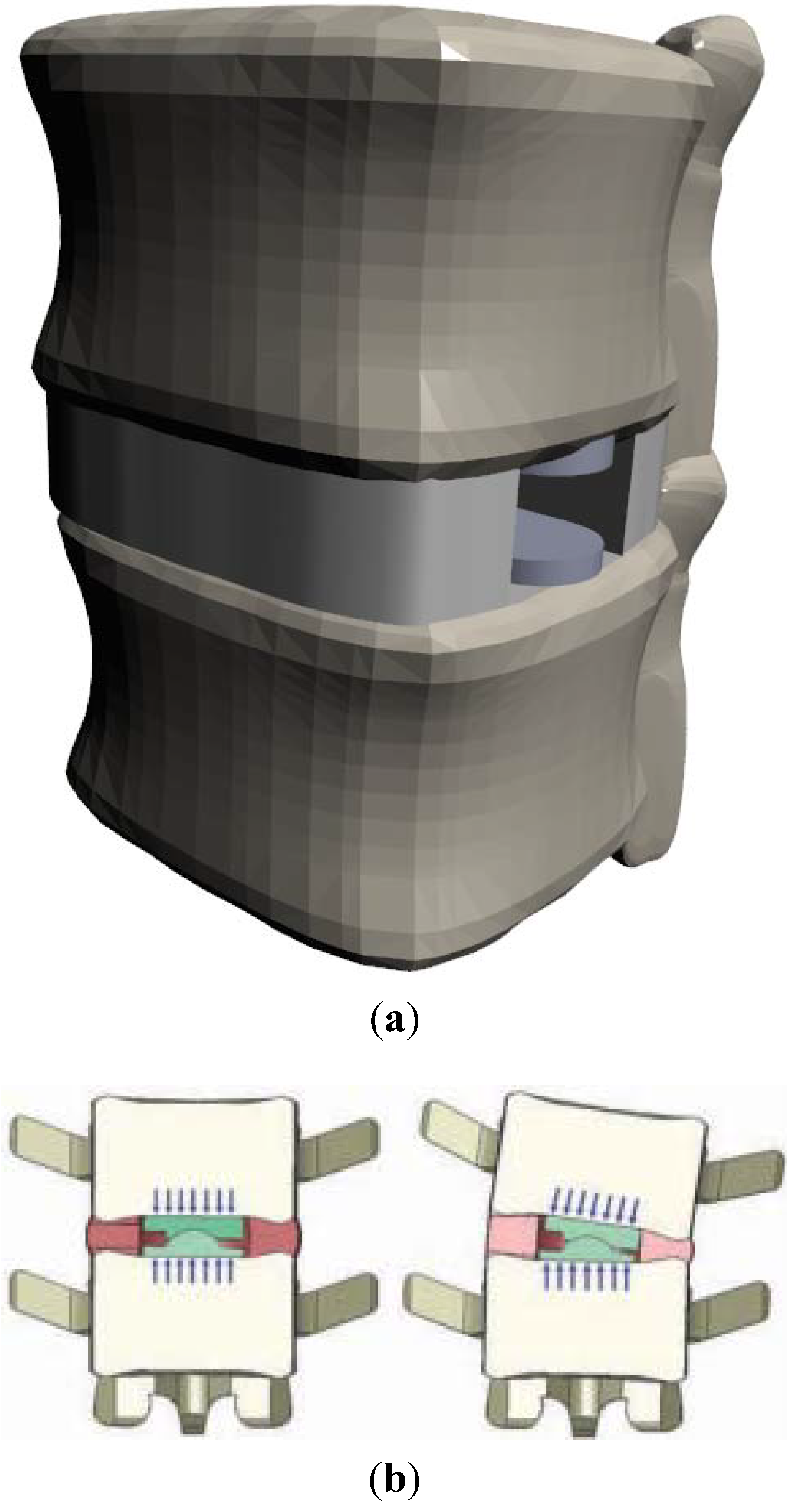
2.1.1. Ball-and-Socket

When designing the ball and socket TDR, a major source of inspiration is the total hip replacement. Hip replacements use a ball and socket design but also experience higher stress and load concentrations than what is needed for TDR. Material selection, therefore, is often inspired by materials used in hip replacement prostheses. The sliding surfaces for the ball and socket bearings are composed of CoCr-CoCr for MoM designs and CoCr-UHMWPE for MoP designs. CoCr alloys are used because they have been found to produce less wear debris in knee and hip replacements [10]. Figure 2 is a drawing of the ball and socket mechanism in these devices to roughly illustrate how they work.
Figure 2. Illustration of working mechanisms of ball-socket devices.
Lubricants 03 00346 g002

2.1.2. One Piece

The one piece bearing design is a recent development for TDR. The aim of this design is to more adequately mimic the natural disc behavior through the implant. One piece designs reduce the number of surfaces on which wear can occur and they reduce hypermobility of the joint. Additionally, since these are made of a softer elastomer, they also mimic the cushioning provided by the natural intervertebral disc.

2.2. Implant Materials

Biomaterials being used in current implant designs are: cobalt-chromium alloy (CoCr), titanium (Ti), diamond-like carbon (DLC) coatings, ultrahigh-molecular-weight-polyethylene (UHMWPE), silicone, and a polyurethane-polycarbonate elastomer (PU-PC) [15,25]. Ti is typically used as the material to interface between implant and bone; the other materials listed are used as bearing materials for each design. Material selection is not entirely random; most of the early design ideas for TDR implants are a result of current designs in other total joint replacements. Bearing material selections are typically inspired by hip or knee replacement devices.

3. Causes for Failure

3.1. Device Degradation

Orthopedic implant failure can often be traced to the degradation of an implant. There are two mechanisms for the degradation of TDR implants: wear and corrosion [27]. This is to be expected with articulating bearings in harsh environments.

3.1.1. Metal-on-Polymer

When comparing mobile and fixed MoP devices, one can compare Prodisc-L with CHARITE TDR devices [28]. The mobile design in the CHARITE allows the UHMWPE core to shift as the back bends, which reduces stress experienced by posterior facets [28]. While this implies that the mobile bearing is a better design due to smaller loadings on facets and adjacent bodies, four degree of freedom (DOF) and 5DOF tests indicate higher UHMWPE wear mass loss in the CHARITE design [29,30].
Removed Mobidisc implants revealed that large UHMWPE particles surrounding the implant that caused an inflammatory response [21]. Particles were also found in patients with the Activ-L implant, but they were smaller and still triggered an inflammatory response [21]. Wear particles from UHMWPE tend to be spherical and ranging between 0.5 and 10 microns in diameter [31,32]. This means that even though UHMWPE is not chemically reactive and spherical particles are typically nonreactive as well, the large particle size would induce inflammatory and osteolytic responses [31,32,33].
In studies that have retrieved UHMWPE cores from used implants show measurable wear on the surface of the bearing [18,34]. As in hip replacements, multidirectional scratches and some penetration into the polymer were observed. Surface wear and damage are observed near the center of the core as a result of adhesive/abrasive mechanisms [18,34,35]. Some long term retrieval studies of the Prodisc-L also found third body wear and end plate impingement, often coupled with burnishing of the metallic endplates [36,37]. Impingement was also demonstrated in both Activ-L, CHARITE, and Mobidisc implant designs [21,38]. Retrieval studies also observed wear and damage that was similar to that of hip and knee implants. Central dome regions of the UHMWPE core exhibited microscopic scratches resembling the wear patterns of knee and hip MoP devices [35,36,39]. Scratch penetration into the polymer core increases at a decreasing rate with implantation time [34,40]. This behavior is similar to wear seen in hip implants. These studies, however, found this damage to be insignificant. The rim of the core was subject to extensive plastic deformation and fracture, which is sometimes observed in total knee replacements [34,41].

3.1.2. Metal-on-Metal

In hip arthroplasty it was noticed that MoP bearing surfaces produced high volume wear rates when compared to MoM devices. UHMWPE joints can wear at a rate over 100 microns per year [33]. MoM bearings were introduced to hip replacements to produce less wear debris and reduce particle-driven osteolysis [15,42,43]. However, in spite of the decrease in wear volume, the number of wear particles actually increased [44]. This is due to particle size differences in the materials. While MoP devices tend to wear at faster rates yielding more volume loss, MoM devices produce a large number of particles which range in size from 10 to 119 nm [45]. When compared to the particle size of UHMWPE particles on the order of microns in diameter, this means a substantial increase in the amount of reactive particles and reactive surface area of debris. This was especially damaging when the bearing was made of a reactive cobalt-based alloy, which is a major concern for the application of MoM bearings in TDR [15,44,46].
Although limiting volumetric wear is desirable, that is not all that must be considered. MoM bearings tend to produce more particles, which are much smaller than those produced by MoP bearings [44,46]. CoCr is used for these bearings because it has good mechanical properties [47,48] hard and passive in the biological environment [47,49,50,51]. It is not, however, inert. CoCr wear particles are chemically reactive within the body. This, combined with the large surface area of the debris, make the particles susceptible to electrochemical processes, which can lead to corrosion of the material and implant within the body [50,52,53]. Unlike the UHMWPE debris mentioned above, MoM bearing wear to produce fine, needle and fiber-shaped particles. This particle shape is chemically more reactive in nature, thus contributing to corrosion, tribocorrosion, and toxic and biological responses, such as metallosis, pseudotumors, biological reactions, osteolysis, and inflammation [15,44,46,54,55].
MoM implants reduce corrosion and negative biological response through passive oxide films [56,57]. Cyclic loading of these implants can lead to fretting which can disrupt oxide films and limit their effectiveness [52,53,58,59,60]. Corrosion in these implants is often a result of this fretting wear, which deteriorates the passive oxide layer. Corrosive wear usually produces particles of cobalt or chromium oxides or metal ions, which can build up or bind to proteins within the body causing severely negative biological response [27,42,43,52,60]. This response includes toxic reactions as well as metal build up and bone decay which are absolutely detrimental to patient health.

3.1.3. Polymer-on-Polymer

In addition to TDR, some Nubac, a PEEK-on-PEEK device proposes a nucleus replacement solution to minimize some of the biomechanical incompatibilities of TDR. This type of devices utilizes a PEEK-on-PEEK (PoP) bearing design, which replaces the nucleus pulposus. This design is not usually pursued because nucleus replacements have a tendency to be expelled by the body naturally. The Nubac device, however, showed a low risk of expulsion [22]. This device shows promise as, in addition to resisting expulsion, the fatigue resistance and wear resistance of PEEK. Preclinical cadaver and animal tests show that the device does not have detectible wear debris or any negative biological response to implantation [22]. There are issues, however, with device rejection and biological reactions. Long-term clinical trials showed an unacceptable rate of device migration with Nubac, which, in preclinical trials, showed little to no risk [61]. This migration was severe enough to have the device move into surrounding muscle tissue [61].

3.1.4. Diamond-Like Carbon

One disc design, the Baguera-L (See Table 1), moves to reduce the amount of metal wear debris by utilizing a DLC coating on the Ti endplate. DLC is known for its wear resistance and having low friction [62]. These properties make it an ideal candidate for ball and socket bearings in TDR. In spite of its superior wear resistance DLC has issues with long-term adhesion to the substrate.
DLC films, however, are prone to failure and delamination. Delamination primarily occurs due to corrosion of the substrate by body fluids that pass through pinholes in the DLC film. Delamination can also be driven by pitting corrosion under pinholes over time. A corrosive electrolyte may form and begin to corrode the substrate to fuel local debonding [62,63]. This local debonding can induce delamination through corrosion cracking (CC) and stress corrosion cracking (SCC) [62,64].

3.1.5. One Piece

An early design for a singular piece bearing in a TDR implant is the Acroflex disc design by Acromed Corporation. This design uses a polyolefin rubber to mimic the mechanical behavior of a natural disc. Although the device was tested for biological and biomechanical compatibility prior to clinical trials [25,65,66,67,68], patients suffered core material tears and failure mechanisms associated with fatigue [25]. Recent designs have employed PUPC as a core material which has a longer fatigue life.
Even with the improved elastomeric core, these devices could still fail due to PUPC tears or loss of adhesion between the different materials (PUPC-Ti, Ti-bone, or PUPC-bone). Since these designs are still fairly young, evaluating wear and corrosion resistance, as well as effectiveness, for these next-generation PUPC TDR designs require more long-term clinical testing [3,15,25].

3.2. The Body’s Response

3.2.1. Biological Response

In TDR implants the biological response to wear debris is based on number of particles, particle size, particle shape, and chemical composition of the debris [27]. This indicates that biological responses are TDR-design and material dependent. Material-independent responses include inflammation and osteolysis. Osteolysis is often a result of the inflammatory response.
Osteolysis is a mode of degradation which involves the destruction of bone [69]. In the case of orthopedic implants and arthroplasty, osteolysis occurs at the interface between bone and implant. Osteolysis in TDR implants is primarily driven by micro-motion of the implant and the body’s biological response to wear debris [33]. It is easy to picture how motion would cause bone degeneration: just like the periodic maneuvering of a shovel in soft clay will loosen and remove some clay. The osteolytic response to debris particles, however, is not so straight forward.
Bone growth and maintenance are the results of equilibrium responses of bone growth and resorption, which are driven by osteoblasts and osteoclasts, respectively. Debris particles disrupt bone homeostasis [27] through an inflammatory response which in turn stimulates the maturation of osteoclasts increasing bone resorption [27,33]. The combination of these wear processes leads to increased wear rates over time as resorption loosens the device, thus, creating more space for osteolysis-causing motion and debris [70].
Osteolysis is a prominent mode of failure for total joint replacements including TDR [71]. According to some studies osteolysis is not as prevalent TDR due to it having a smaller range of motion than hip and knee replacements, which would indicate smaller wear tracks and fewer debris particles. These sources reported that wear particles do remain a concern in spinal implants because they indirectly induce osteoclastogenesis which can lead to bone resorption and inflammation [15,59,72,73]. This limited wear of TDR, however, is not necessarily the case for MoM implants. A review of spine implant debris by Hallab reveals that though MoP hip implants have a substantially higher wear volumerate than TDR, MoM hip and intervertebral disc replacements have comparable wear rates [27].
Problematic responses to CoCr MoM wear particles include metal hypersensitivity, metallosis, the formation of pseudotumors, and vasculitis [15,44,46,74,75,76]. Metal-specific biological responses are a result of wear particle chemistry and shape. Co and Cr ions are chemically reactive and therefore are pro-inflammatory [27,45]. Aside from the chemical nature of CrCo debris, shape is an important factor dictating biological response. As seen historically with asbestos fibers, fiber shaped particles from TDR wear cause greater inflammatory response than round particles through a natural response called “danger signaling” [32,77,78,79].

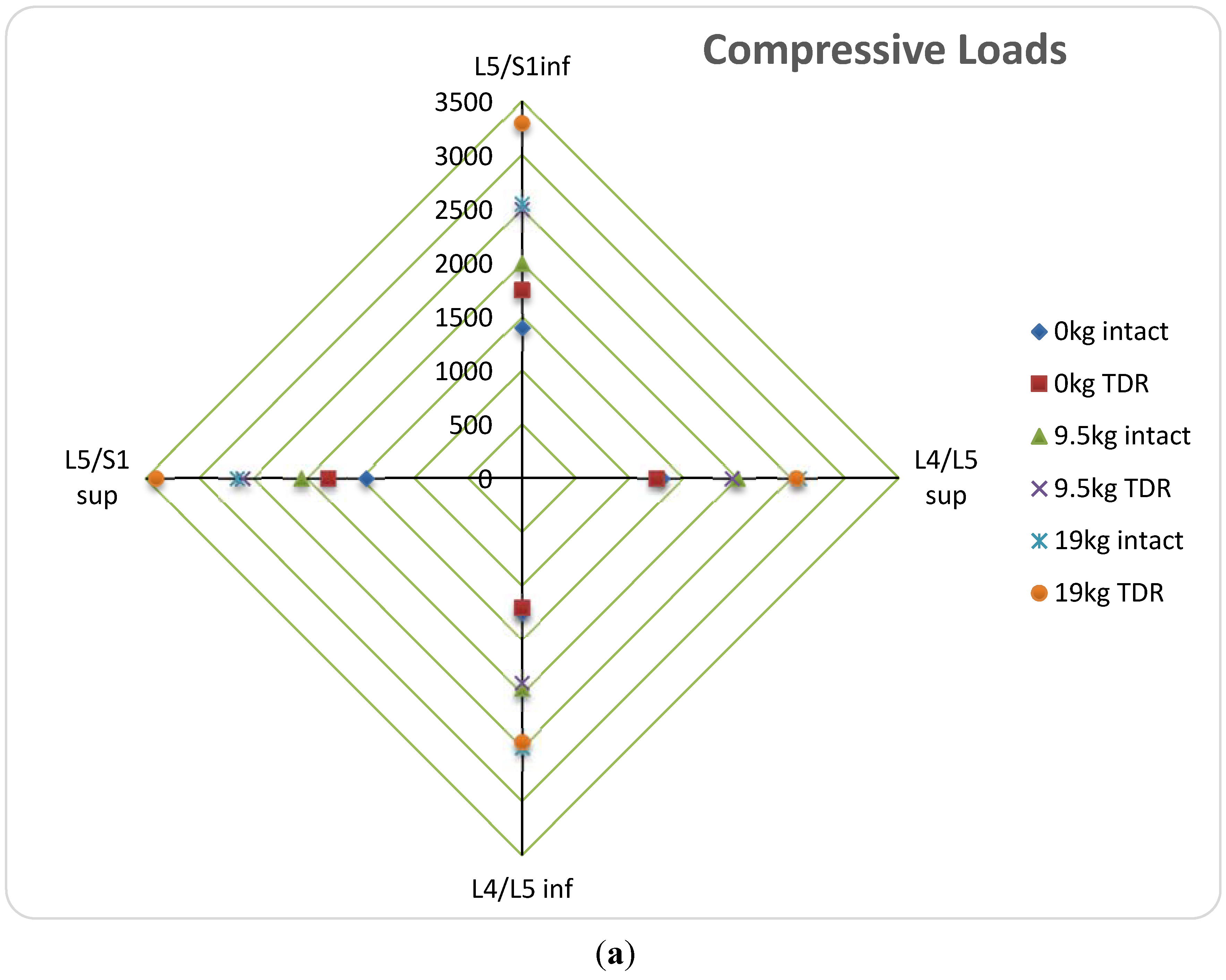
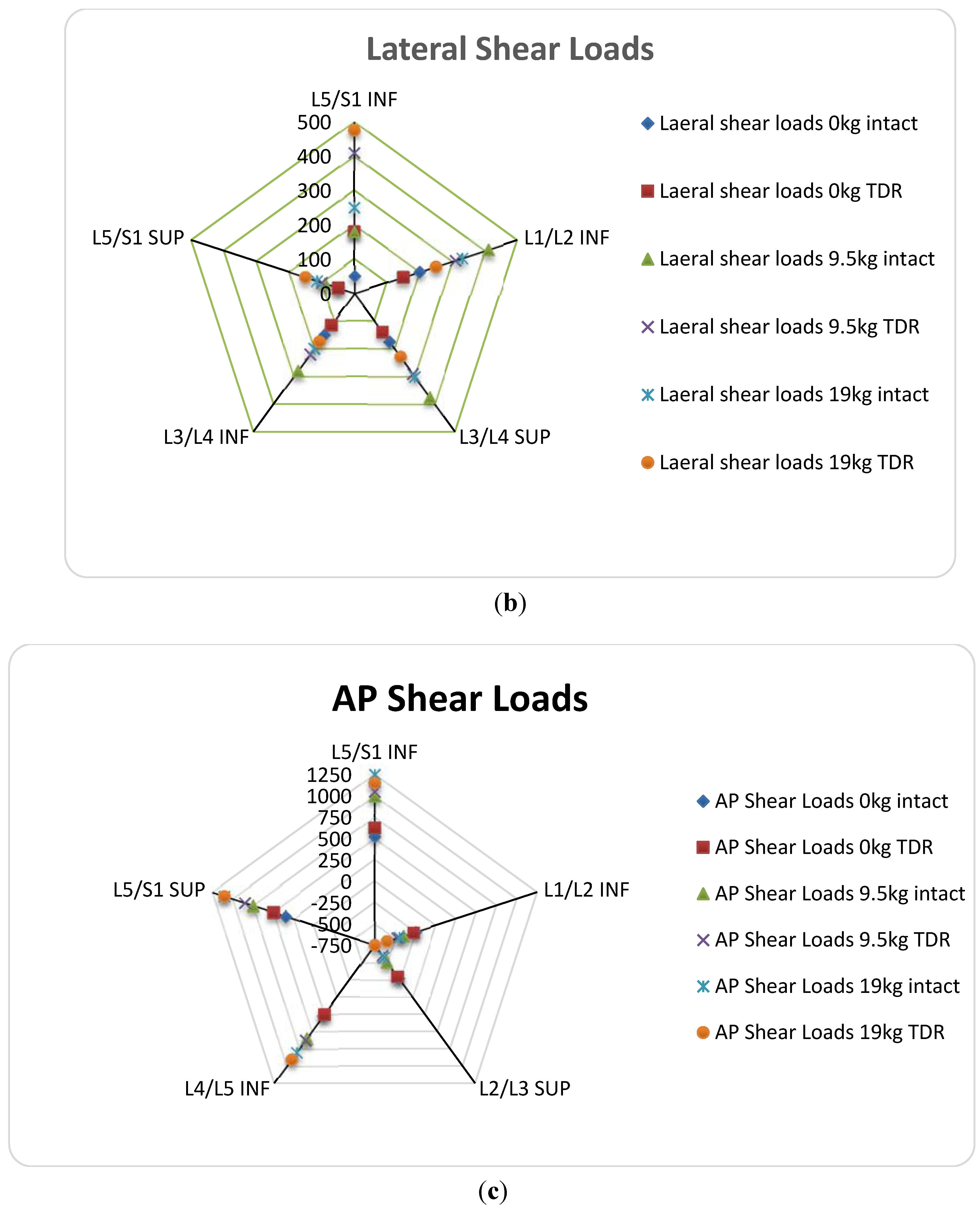
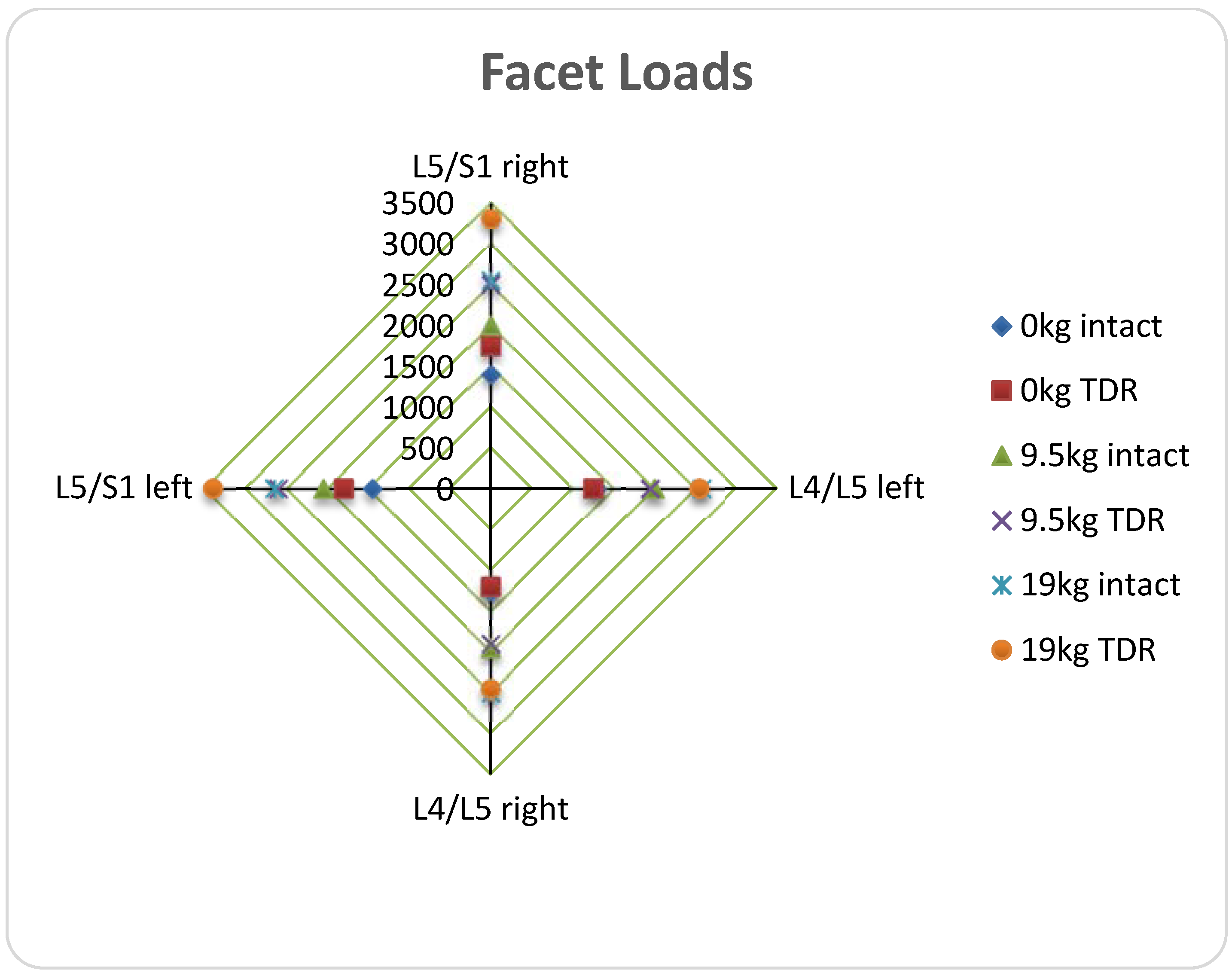
3.2.2. Mechanical Response

A problem that separates TDR from other joint replacements lies in the complex duty of the intervertebral disc. It is not merely a joint which connects two moving parts. The intervertebral disc, especially in the lumbar region, serves to resist motion and reduce stress concentrations in the adjacent level tissue [4,9].

(a) Ball-and-Socket Bearing

Ball and socket bearings to not completely replicate the functions of the natural IVD. These bearings tend to be axially rigid and are not designed to resist bending or rotational moments, allowing motion to occur in excess of that permitted by the natural disc [9,80]. These qualities can lead to changes in range of motion (ROM), segmental lordosis, or facet stressing [3,15,26,81,82,83].
Among limited number of available reports, the Spine Institute at The Ohio State University (OSU) used a hybrid biomechanical model to analyze lumbar function after implantation of Prodisc-L TDR under different external loading conditions. This model was made after an individual male and uses a flexible multi-body dynamic analysis system [9]. The model looked at TDR at all lumbar levels, and examined vertebral body loading, ROM, and ligament and facet joint forces. These measurements were taken when the subject was not exerting at all and when he was asked to lift 9.5 and 19 kg separately. The figures below are drawn based on the OSU study. In the figures, the abbreviations SUP and INF represent the interface at the superior and inferior levels of the implant respectively. Figure 3 [9] shows mean values of data from a virtual model simulation of vertebral loadings from the OSU study at different implantation levels. The original data can be found in reference [9]. Before reviewing these data some terminology should be reviewed. Numbers such as L5 and S1 describe specific vertebrae. L5 is the fifth and most inferior lumbar (L) vertebrae. S1 is representative of the sacrum which is inferior to the spine and is immobile.

(b) Vertebral Body Stresses

Figure 3 below shows approximate mean value data for different simulated loadings based on disc type and implantation level. The information is organized such that data for a given implantation level are reported in the same color. The study found that the substantial differences in performance between TDR and the natural disc lied closer to L5/S1 level. Therefore, the information below focuses on that region. After examining Figure 3 (a) it can be noted that in general at these lower lumbar levels (L4/L5 to L5/S1) that compressive loads apply on the interfacing vertebral bodies. These loading changes are primarily due to high stiffness of the implant and discontinuity at the bone-implant interface. Similar trends of excess loadings due to TDR can be noted for vertebral body shear loadings as well. In the case of AP shear loading, seen in Figure 3 (c) the direction and magnitude of the shear are dependent upon the shape of the spine. Since the resistance to motion is less with TDR, less shear loading is exhibited with TDR than an intact disc in regions of spinal curvature. This, however would indicate higher loading of the nearby ligaments.

(c) ROM; Facet and Ligament Stresses

A study was conducted by Burger et al. to examine lumbar facet forces on cadavers after Prodisc-L TDR [84]. A facet is another joint at which adjacent vertebrae interface. The purpose of the facet joint is to aid in the inhibition of rotation and excess motion in order to keep vertebrae aligned. Each level has 2 facet joints, one on the left and one on the right side of the spinous process.
Figure 3. Selected mean data from a published simulated work in reference [9]. (a) Comparison of simulated compressive vertebral loads before and after TDR implantation, based on exterior loading and implantation level; (b) Comparison of simulated anterior-posterior shear loading at vertebral body interface before and after TDR implantation based exterior loading and implantation level; (c) Comparison of simulated lateral shear loading at vertebral body interface before and after TDR implantation based on exterior loading and implantation level [9].
Lubricants 03 00346 g003aLubricants 03 00346 g003b
Figure 4. Selected data from simulated facet load comparison of natural disc to TDR implantation based on implantation level and exterior loading [9].
Lubricants 03 00346 g004
Figure 4 shows mean adjacent facet loads for TDR at each level according to the OSU study. Once again, facet loading most substantially increases with TDR implantation at L5/S1 level. Additionally, the OSU study shows increased ligament loading and ROM in all directions specifically at L4/L5 and L5/S1 levels of implantation [9]. The most drastic ROM difference occurred in the transverse plane while the motion was twisting about the spine’s axis [9].
Cadaveric study performed has also examined lumbar implantation. Similarly, those concluded that lateral bending and axial rotation result in the most significant increases in facet loading [38,84,85].
This increase in facet loading and ROM can cause stress fractures of the pars and bilateral pedicle, as well as adjacent level disc degeneration [25,86,87,88,89]. This indicates much need for improvement of TDR implants in the mechanical regime. The articulating ball and socket joints, while they soothe pain, tend to be a source of mechanical issues and injury risk for patients.
Figure 5. (a) Drawing of XL-TDR implanted at L4/L5 level shows retention of natural disc tissue and structure with lateral TDR implantation [90]; (b) Illustration of Nubac nucleus replacement (used with permission) [22].
Lubricants 03 00346 g005
Two possible solutions for the mechanical incompatibilities as shown above are: 1P bearings and partial replacements like Nubac and the extreme lateral TDR (XL-TDR) by NuVasive. The XL-TDR is designed to limit the amount of natural tissue removed. This allows the body to retain some of its natural cushioning and resistance to motion. Figure 5a shows how the lateral insertion can eliminate some need for tissue removal. Figure 5b is an illustration of the nucleus replacement and how it helps preserve natural motion.
The XL-TDR design improves on other MoM implants by preventing hypermobility, providing some natural biomechanical support, and provides a unique look at modern TDR implant designs [90].

4. One Piece

In order to correct problems seen with ball and socket TDR implants, the one piece bearing employs an elastomer to mimic the body’s natural motion [3,15,83]. The current implant designs using the PUPC bearing passed fatigue and endurance bending tests prior to introduction into clinical trials [25]. These cores were found to resist tearing and wear and were found to be more biomechanically compatible with natural motions [25]. As mentioned before, these devices must be studied further in more long term trials to effectively understand the body’s response.
Table 2 below gives a brief summary of failure mechanisms based on implant materials and design.
Table 2. Summary of common problems of different implant materials and their effects leading to device failure.
Bearing TypeMaterialProblemsEffectsReference
Ball and socketCoCrReactive wear ions Fibrous particulesMetal sensitivity reactions, Inflammation, Osteolysis[19,31,68,91,92]
Metallosis [15,44,61]
No shock absorptionCompressive stresses on vertebral bodies[9]
UHMWPEWear debris large wear volumeBone resorption, Osteolysis[31,92,93]
[18,31]
Plastic deformation [18]
Increased ROMFacet and ligament loading[16]
No shock absorptionCompressive stresses on vertebral bodies[9]
PEEKProsthesis migrationBiomechanical incompatibility, stress on remaining annulus, total ejection of device[61]
Endplate reactionSevere biological rejection[61]
1PPUPCMore studies necessary [25]

5. Future Prospects

TDR looks to be a suitable treatment for lumbar DDD. More specifically, studies show that the elastomeric 1P bearing TDR are the future of DDD treatment [94,95]. These 1P bearings provide a solution to common problems seen with ball and socket TDR implants [20]. A hurdle for these designs is finding suitable core materials for biocompatibility and adhesion to the vertebral bodies [25]. This problem seems to have been solved by the use of the PUPC cores in the one piece (1P) bearing implant design, but more research still needs to be done for these designs [15]. Although the XL-TDR provides a solution to some of the problems with the traditional ball and socket design, they still involve articulating metal surfaces which can be the site of wear and corrosion. For this reason, research indicates that the 1P bearing would be the ideal design for the future of TDR. Perhaps even a 1P design placed laterally could further improve the TDR implant design.

6. Conclusions

Total disc replacement (TDR) are an effective solution to degenerative disc disease (DDD), but currents designs still require improvement to be better substitutes for a healthy disc. Ball and socket bearing designs, or any implant involving articulating surfaces increase the risk of failure due to an introduction of more wear and corrosion surfaces. These articulating bearings also do not adequately resist motion and provide cushioning or stability for the lumbar spine (with the exception of the XL-TDR). This would imply that the future of TDR employs a flexible elastomer bearing which can better mimic a natural intervertebral disc (IVD). While this seems like a natural solution, this design type must be looked into further and studied more closely before any conclusions can be drawn.

Acknowledgments

Authors wish to thank Alex Fang for support during preparation of this manuscript. We also wish to acknowledge Dongsheng Zhou and Guodong Wang of Shandong University Orthopedic Hospital for providing surgical images.

Author Contributions

John Reeks conducted review, analyzed data, and drafted the manuscript. Hong Liang directed review and wrote the paper.

Conflicts of Interest

The author declares that there is no conflict of interest.

References

  1. Pleis, J.; Schiller, J.; Benson, V. Summary health statistics for U.S. adults: National Health Interview Survey, 2010. Vital Health Stat. 2012, 10, 1–207. [Google Scholar]
  2. Karajan, N. Multiphasic intervertebral disc. mechanics: Theory and application. Arch. Comput. Methods Eng. 2012, 19, 261–339. [Google Scholar] [CrossRef]
  3. Lazennec, J.Y.; Even, J.; Skalli, W.; Rakover, J.P.; Brusson, A.; Rousseau, M.A. Clinical outcomes, radiologic kinematics, and effects on sagittal balance of the 6 df LP-ESP lumbar disc prosthesis. Spine J. 2014, 14, 1914–1920. [Google Scholar] [CrossRef] [PubMed]
  4. Neumann, D.A. Kinesiology of the Musculoskeletal System: Foundations for Rehabilitation; Elsevier Health Sciences: St. Louis, MO, USA, 2013. [Google Scholar]
  5. Bogduk, N. Clinical Anatomy of the Lumbar Spine and Sacrum; Churchill Livingstone: London, UK, 2005. [Google Scholar]
  6. Markolf, K.L.; Morris, J.M. The structural components of the intervertebral disc. J. Bone Joint Surg. 1974, 56, 675–687. [Google Scholar] [PubMed]
  7. Rothman, R.H.; Simeone, F.A. The spine. J. Pediatr. Orthop. 1992, 12, 549. [Google Scholar] [CrossRef]
  8. Gloria, A.; De Santis, R.; Ambrosio, L.; Causa, F.; Tanner, K.E. A multi-component fiber-reinforced PHEMA-based hydrogel/HAPEX device for customized intervertebral disc prosthesis. J. Biomater. Appl. 2011, 25, 795–810. [Google Scholar] [CrossRef] [PubMed]
  9. Knapik, G. Use of a personalized hybrid biomechanical model to assess change in lumbar spine function with a TDR compared to an intact spine. Eur. Spine J. 2012, 21, 641–652. [Google Scholar] [CrossRef]
  10. Serhan, H.; Mhatre, D.; Defossez, H.; Bono, C.M. Motion-preserving technologies for degenerative lumbar spine: The past, present, and future horizons. SAS J. 2011, 5, 75–89. [Google Scholar] [CrossRef] [PubMed]
  11. Gornet, M.F.; Burkus, J.K.; Dryer, R.F.; Peloza, J.H. Lumbar disc arthroplasty with Maverick disc versus stand-alone interbody fusion: A prospective, randomized, controlled, multicenter investigational device exemption trial. Spine 2011, 36, E1600–E1611. [Google Scholar] [CrossRef] [PubMed]
  12. Kumar, M. Correlation between sagittal plane changes and adjacent segment degeneration following lumbar spine fusion. Eur. Spine J. 2001, 10, 314–319. [Google Scholar] [CrossRef] [PubMed]
  13. Kumar, M. Long-term follow-up of functional outcomes and radiographic changes at adjacent levels following lumbar spine fusion for degenerative disc disease. Eur. Spine J. 2001, 10, 309–313. [Google Scholar] [CrossRef] [PubMed]
  14. Cakir, B.; Richter, M.; Schmoelz, W.; Schmidt, R.; Reichel, H.; Wilke, H.J. Resect or not to resect: The role of posterior longitudinal ligament in lumbar total disc replacement. Eur. Spine J. 2012, 21, 592–598. [Google Scholar] [CrossRef]
  15. Veruva, S.Y.; Steinbeck, M.J.; Toth, J.; Alexander, D.D.; Kurtz, S.M. Which design and biomaterial factors affect clinical wear performance of total disc replacements? A systematic review. Clin. Orthop. Related Res. 2014, 472, 3759–3769. [Google Scholar] [CrossRef]
  16. Takigawa, T.; Espinoza Orías, A.A.; An, H.S.; Gohgi, S.; Udayakumar, R.K.; Sugisaki, K.; Natarajan, R.N.; Wimmer, M.A.; Inoue, N. Spinal kinematics and facet load transmission after total disc replacement. Spine 2010, 35, E1160–E1166. [Google Scholar] [CrossRef] [PubMed]
  17. Kettler, A.; Bushelow, M.; Wilke, H.J. Influence of the loading frequency on the wear rate of a polyethylene-on-metal lumbar intervertebral disc replacement. Eur. Spine J. 2012, 21, S709–S716. [Google Scholar] [CrossRef] [PubMed]
  18. Shkolnikov, Y.P.; Bowden, A.; MacDonald, D.; Kurtz, S.M. Wear pattern observations from TDR retrievals using autoregistration of voxel data. J. Biomed. Mater. Res. B Appl. Biomater. 2010, 94, 312–317. [Google Scholar] [PubMed]
  19. Chen, W.M.; Park, C.; Lee, K.; Lee, S. In situ contact analysis of the prosthesis componentsof Prodisc-L in lumbar spine following total disc replacement. Spine 2009, 34, E716–E723. [Google Scholar] [CrossRef] [PubMed]
  20. Huang, R.C.; Girardi, F.P.; Cammisa, F.P.; Wright, T.M. The implications of constraint in lumbar total disc replacement. J. Spinal Disord. Tech. 2003, 16, 412–417. [Google Scholar] [CrossRef] [PubMed]
  21. Austen, S.; Punt, I.M.; Cleutjens, J.P.; Willems, P.C.; Kurtz, S.M.; MacDonald, D.W.; van Rhijn, L.W.; van Ooij, A. Clinical, radiological, histological and retrieval findings of Activ-L and Mobidisc total disc replacements: A study of two patients. Eur. Spine J. 2012, 21, S513–S520. [Google Scholar] [CrossRef] [PubMed]
  22. Bao, Q.B.; Songer, M.; Pimenta, L.; Werner, D.; Reyes-Sanchez, A.; Balsano, M.; Agrillo, U.; Coric, D.; Davenport, K.; Yuan, H. Nubac disc arthroplasty: Preclinical studies and preliminary safety and efficacy evaluations. SAS J. 2007, 1, 36–45. [Google Scholar] [CrossRef] [PubMed]
  23. Marchi, L.; Oliveira, L.; Coutinho, E.; Pimenta, L. The importance of the anterior longitudinal ligament in lumbar disc arthroplasty: 36-Month follow-up experience in extreme lateral total disc replacement. Int. J. Spine Surg. 2012, 6, 18–23. [Google Scholar] [CrossRef] [PubMed]
  24. McNally, D.; Naylor, J.; Johnson, S. An in vitro biomechanical comparison of Cadisc™-L with natural lumbar discs in axial compression and sagittal flexion. Eur. Spine J. 2012, 21, 612–617. [Google Scholar] [CrossRef]
  25. Pimenta, L.; Springmuller, R.; Lee, C.K.; Oliveira, L.; Roth, S.E.; Ogilvie, W.F. Clinical performance of an elastomeric lumbar disc replacement: Minimum 12 months follow-up. SAS J. 2010, 4, 16–25. [Google Scholar] [CrossRef] [PubMed]
  26. Van den, B. Design of next generation total disk replacements. J. Biomech. 2012, 45, 134–140. [Google Scholar] [CrossRef] [PubMed]
  27. Hallab, N. A review of the biologic effects of spine implant debris: Fact. from fiction. SAS J. 2009, 3, 143–160. [Google Scholar] [CrossRef] [PubMed]
  28. Frelinghuysen, P.; Huang, R.C.; Girardi, F.P.; Cammisa, F.P. Lumbar total disc replacement part I: Rationale, biomechanics, and implant types. Orthop. Clin. North Am. 2005, 36, 293–299. [Google Scholar] [CrossRef] [PubMed]
  29. Vicars, R.; Hyde, P.J.; Brown, T.D.; Tipper, J.L.; Ingham, E.; Fisher, J.; Hall, R.M. The effect of anterior-posterior shear load on the wear of ProDisc-L TDR. Eur. Spine J. 2010, 19, 1356–1362. [Google Scholar] [CrossRef] [PubMed]
  30. Vicars, R.; Prokopovich, P.; Brown, T.D.; Tipper, J.L.; Ingham, E.; Fisher, J.; Hall, R.M. The effect of anterior-posterior shear on the wear of CHARITE total disc replacement. Spine 2012, 37, E528–E534. [Google Scholar] [CrossRef] [PubMed]
  31. Taki, N.; Tatro, J.M.; Nalepka, J.L.; Togawa, D.; Goldberg, V.M.; Rimnac, C.M.; Greenfield, E.M. Polyethylene and titanium particles induce osteolysis by similar, lymphocyte-independent, mechanisms. J. Orthop. Res. 2005, 23, 376–383. [Google Scholar] [CrossRef] [PubMed]
  32. Sieving, A. Morphological characteristics of total joint arthroplasty-derived ultra-high molecular weight polyethylene (UHMWPE) wear debris that provoke inflammation in a murine model of inflammation. J. Biomed. Mater. Res. 2003, 64, 457–464. [Google Scholar] [CrossRef]
  33. Agarwal, S. Osteolysis—basic science incidence and diagnosis. Curr. Orthop. 2004, 18, 220–231. [Google Scholar] [CrossRef]
  34. Kurtz, S.M.; van Ooij, A.; Ross, R.; de Waal Malefijt, J.; Peloza, J.; Ciccarelli, L.; Villarraga, M.L. Polyethylene wear and rim fracture in total disc arthroplasty. Spine J. 2007, 7, 12–21. [Google Scholar] [CrossRef] [PubMed]
  35. McKellop, H.A.; Campbell, P.; Park, S.H.; Schmalzried, T.P.; Grigoris, P.; Amstutz, H.C.; Sarmiento, A. The origin of submicron polyethylene wear debris in total hip arthroplasty. Clin. Orthop. Related Res. 1995, 311, 3–20. [Google Scholar]
  36. Lebl, D. In vivo functional performance of failed Prodisc-L devices: Retrieval analysis of lumbar total disc replacements. Spine 2012, 37, E1209–E1217. [Google Scholar] [CrossRef] [PubMed]
  37. Choma, T. Retrieval analysis of a ProDisc-L total disc replacement. J. Spinal Disord. Tech. 2009, 22, 290–296. [Google Scholar] [CrossRef] [PubMed]
  38. Rundell, S.A.; Day, J.S.; Isaza, J.; Guillory, S.; Kurtz, S.M. Lumbar total disc replacement impingement sensitivity to disc height distraction, spinal sagittal orientation, implant position, and implant lordosis. Spine 2012, 37, E590–E598. [Google Scholar] [CrossRef] [PubMed]
  39. Wang, A.; Essner, A.; Polineni, V.K.; Stark, C.; Dumbleton, J.H. Lubrication and wear of ultra-high molecular weight polyethylene in total joint replacements. Tribol. Int. 1998, 31, 17–33. [Google Scholar] [CrossRef]
  40. Charnley, J.; Halley, D.K. Rate of wear in total hip replacement. Clin. Orthop. Related Res. 1975, 112, 170–179. [Google Scholar]
  41. Wright, T.; Bartel, D. The problem of surface damage in polyethylene total knee components. Clin. Orthop. Related Res. 1986, 205, 67–74. [Google Scholar]
  42. Gornet, M. Prospective study on serum metal levels in patients with metal-on-metal lumbar disc arthroplasty. Eur. Spine J. 2013, 22, 741–746. [Google Scholar] [CrossRef] [PubMed]
  43. Kurtz, S. The latest lessons learned from retrieval analyses of ultra-high molecular weight polyethylene, metal-on-metal, and alternative bearing total disc replacements. Semin. Spine Surg. 2012, 24, 57–70. [Google Scholar] [CrossRef] [PubMed]
  44. Guyer, R.D.; Shellock, J.; MacLennan, B.; Hanscom, D.; Knight, R.Q.; McCombe, P.; Jacobs, J.J.; Urban, R.M.; Bradford, D.; Ohnmeiss, D.D. Early failure of metal-on-metal artificial disc prostheses associated with lymphocytic reaction: Diagnosis and treatment experience in four cases. Spine 2011, 36, E492–E497. [Google Scholar] [CrossRef] [PubMed]
  45. Behl, B.; Papageorgiou, I.; Brown, C.; Hall, R.; Tipper, J.L.; Fisher, J.; Ingham, E. Biological effects of cobalt-chromium nanoparticles and ions on dural fibroblasts and dural epithelial cells. Biomaterials 2013, 34, 3547–3558. [Google Scholar] [CrossRef] [PubMed]
  46. Golish, S.R.; Anderson, P.A. Bearing surfaces for total disc arthroplasty: Metal-on-metal versus metal-on-polyethylene and other biomaterials. Spine J. 2012, 12, 693–701. [Google Scholar] [CrossRef] [PubMed]
  47. Gotman, I. Characteristics of metals used in implants. J. Endourol. 1997, 11, 383–389. [Google Scholar] [CrossRef] [PubMed]
  48. Asphahani, A.I.; Kumar, P.; Hickl, A.J.; Lawley, A. Properties and characteristics of cast, wrought, and powder metallurgy (P/M) processed cobalt-chromium-molybdenum implant materials. In Corrosion and Degradation of Implant Materials: Second Symposium; Fraker, A.C., Griffin, C.D., Eds.; ASTM International: West Conshohocken, PA, USA, 1985. [Google Scholar]
  49. Perkins, L. Evaluation of Bone Fixation Implants. Texas A&M University, College Station, TX, USA, December 2012. [Google Scholar]
  50. Gurappa, I. Characterization of different materials for corrosion resistance under simulated body fluid conditions. Mater. Charact. 2002, 49, 73–79. [Google Scholar] [CrossRef]
  51. Gurrappa, I. Corrosion and its importance in selection of materials for biomedical applications. Corros. Prev. Control 2001, 48, 23–37. [Google Scholar]
  52. Taksali, S. Material considerations for intervertebral disc replacement implants. Spine J. 2004, 4, 231S. [Google Scholar] [CrossRef] [PubMed]
  53. Pourbaix, M. Electrochemical corrosion of metallic biomaterials. Biomaterials 1984, 5, 122–134. [Google Scholar] [CrossRef] [PubMed]
  54. Kirkpatrick, J. Corrosion on spinal implants. J. Spinal Disord. Tech. 2005, 18, 247–251. [Google Scholar] [PubMed]
  55. Michel, R. Trace element burdening of human tissues due to the corrosion of hip-joint prostheses made of cobalt-chromium alloys. Arch. Orthop. Trauma. Surg. 1984, 103, 85–95. [Google Scholar] [CrossRef] [PubMed]
  56. Pound, B.G. Passive films on metallic biomaterials under simulated physiological conditions. J. Biomed. Mater. Res. Part A 2014, 102, 1595–1604. [Google Scholar] [CrossRef]
  57. Jacobs, J.J. Corrosion of metal orthopaedic implants. JBJS J. Bone Joint Surg. 1998, 80, 268–282. [Google Scholar]
  58. Jacobs, J.J.; Shanbhag, A.; Glant, T.T.; Black, J.; Galante, J.O. Wear debris in total joint replacements. J. Am. Acad. Orthop. Surg. 1994, 2, 212–220. [Google Scholar] [PubMed]
  59. Waterhouse, R.B. Fretting wear. Wear 1984, 100, 107–118. [Google Scholar] [CrossRef]
  60. Zeh, A.; Becker, C.; Planert, M.; Lattke, P.; Wohlrab, D. Time-dependent release of cobalt and chromium ions into the serum following implantation of the metal-on-metal Maverick type artificial lumbar disc (Medtronic Sofamor Danek). Arch. Orthop. Trauma Surg. 2009, 129, 741–746. [Google Scholar] [CrossRef] [PubMed]
  61. Pimenta, L. Lessons learned after 9 yearsʼ clinical experience with 3 different nucleus replacement devices. Semin. Spine Surg. 2012, 24, 43–47. [Google Scholar] [CrossRef]
  62. Hauert, R.; Thorwarth, K.; Thorwarth, G. An overview on diamond-like carbon coatings in medical applications. Surf. Coat. Technol. 2013, 233, 119–130. [Google Scholar] [CrossRef]
  63. Chandra, L. The effect of biological fluids on the adhesion of diamond-like carbon films to metallic substrates. Diamond Related Mater. 1995, 4, 852–856. [Google Scholar] [CrossRef]
  64. Falub, C.V. In vitro studies of the adhesion of diamond-like carbon thin films on CoCrMo biomedical implant alloy. Acta Mater. 2011, 59, 4678–4689. [Google Scholar] [CrossRef]
  65. Enker, P. Artificial disc replacement. Preliminary report with a 3-year minimum follow-up. Spine 1993, 18, 1061–1070. [Google Scholar] [CrossRef] [PubMed]
  66. Serhan, H.; Ross, R.; Lowery, G.; Fraser, R. Biomechanical characterization of a new lumbar disc prosthesis. J. Bone Joint Surg. Br. 2002, 84, 215. [Google Scholar]
  67. Moore, R. The biologic response to particles from a lumbar disc prosthesis. Spine 2002, 27, 2088–2094. [Google Scholar] [CrossRef] [PubMed]
  68. Fraser, R. AcroFlex design and results. Spine J. 2004, 4, S245–S251. [Google Scholar] [CrossRef]
  69. Credo Reference (Firm). Merriam-Websterʼs Medical Desk Dictionary; Thomson Delmar Learning: Clifton Park, NY, USA, 2006; p. 1. [Google Scholar]
  70. Per Aspenberg, P.H. Periprosthetic bone resorption. Particles versus movement. J. Bone Joint Surg. Br. 1996, 78, 641–646. [Google Scholar] [PubMed]
  71. Kang, J. Chronic failure of a lumbar total disc. Replacement with osteolysis. report of a case with nineteen-year follow-up. JBJS J. Bone Joint Surg. 2008, 90, 2230. [Google Scholar]
  72. Bisseling, P.; Zeilstra, D.J.; Hol, A.M.; van Susante, J.L.C. Metal ion levels in patients with a lumbar metal-on-metal total disc replacement SHOULD WE BE CONCERNED? J. Bone Joint Surg. Br. 2011, 93, 949–954. [Google Scholar] [CrossRef] [PubMed]
  73. Black, J. In Vivo Corrosion of a Cobalt-Base Alloy and Its Biological Consequences, in Biocompatibility of Co-Cr-Ni Alloys; Springer: New York, NY, USA, 1988; pp. 83–100. [Google Scholar]
  74. Cavanaugh, D. Delayed hyper-reactivity to metal ions after cervical disc arthroplasty: A case report and literature review. Spine 2009, 34, E262–E265. [Google Scholar] [CrossRef] [PubMed]
  75. Shang, X.; Wang, L.; Kou, D.; Jia, X.; Yang, X.; Zhang, M.; Tang, Y.; Wang, P.; Wang, S.; Xu, Y.; Wang, H. Metal. hypersensitivity in patient with posterior lumbar spine fusion: A case report and its literature review. BMC Musculoskelet. Disord. 2014, 15, 314. [Google Scholar] [CrossRef] [PubMed]
  76. Jacobs, J.J.; Hallab, N.J.; Urban, R.M.; Wimmer, M.A. Wear particles. J. Bone Joint Surg. 2006, 88, 99–102. [Google Scholar] [CrossRef] [PubMed]
  77. Laquerriere, P. Importance of hydroxyapatite particles characteristics on cytokines production by human monocytes in vitro. Biomaterials 2003, 24, 2739–2747. [Google Scholar] [CrossRef] [PubMed]
  78. Bruch, J. Response of cell cultures to asbestos fibers. Environ. Health Perspect. 1974, 9, 253. [Google Scholar] [CrossRef] [PubMed]
  79. Dostert, C. Innate immune activation through Nalp3 inflammasome sensing of asbestos and silica. Science 2008, 320, 674–677. [Google Scholar] [CrossRef] [PubMed]
  80. Botolin, S. Facet joint biomechanics at the treated and adjacent levels after total disc replacement. Spine 2011, 36, E27–E32. [Google Scholar] [PubMed]
  81. Chung, S. Biomechanical effect of constraint in lumbar total disc replacement: A study with finite element analysis. Spine 2009, 34, 1281–1286. [Google Scholar] [CrossRef] [PubMed]
  82. O’Leary, P.; Nicolakis, M.; Lorenz, M.A.; Voronov, L.I.; Zindrick, M.R.; Ghanayem, A.; Havey, R.M.; Carandang, G.; Sartori, M.; Gaitanis, I.; et al. Response of CHARITE total disc replacement under physiologic loads: Prosthesis component motion patterns. Spine J. 2005, 5, 590–599. [Google Scholar] [CrossRef] [PubMed]
  83. Heuer, F.; Schmidt, H.; Klezl, Z.; Claes, L.; Wilke, H.J. Stepwise reduction of functional spinal structures increase range of motion and change lordosis angle. J. Biomech. 2007, 40, 271–280. [Google Scholar] [CrossRef] [PubMed]
  84. Botolin, S.; Puttlitz, C.; Baldini, T.; Petrella, A.; Burger, E.; Abjornson, C.; Patel, V. Facet joint biomechanics at the treated and adjacent levels after total disc replacement. J. Bone Joint Surg. Br. 2012, 94, 143–143. [Google Scholar]
  85. Rundell, S. Total disc replacement positioning affects facet contact forces and vertebral body strains. Spine 2008, 33, 2510–2517. [Google Scholar] [CrossRef] [PubMed]
  86. Phillips, F.; Diaz, R.; Pimenta, L. The fate of the facet joints after lumbar total disc replacement: A clinical and MRI study. Spine J. 2005, 5, S75. [Google Scholar] [CrossRef]
  87. Shim, C.S. CHARITE versus ProDisc—A comparative study of a minimum 3-year follow-up. Spine 2007, 32, 1012–1018. [Google Scholar] [CrossRef] [PubMed]
  88. Mathew, P. Bilateral pedicle fractures following anterior dislocation of the polyethylene inlay of a ProDisc artificial disc replacement: A case report of an unusual complication. Spine 2005, 30, E311–E314. [Google Scholar] [CrossRef] [PubMed]
  89. Schulte, T. Acquired spondylolysis after implantation of a lumbar ProDisc II prosthesis: Case report and review of the literature. Spine 2007, 32, E645–E648. [Google Scholar] [CrossRef] [PubMed]
  90. Pimenta, L.H.; Marchi, L.; Oliveira, L. Lumbar total disc replacement with a ball and socket metal on metal device: Up to 60-months follow-up. Spine J. 2012, 12, S104. [Google Scholar] [CrossRef]
  91. Moghadas, P. Wear in metal-on-metal total disc arthroplasty. Proc. Inst. Mech. Eng. 2013, 227, 356–361. [Google Scholar] [CrossRef]
  92. Dong-wook, K.; Lee, K.-Y.; Jun, Y.; Lee, S.J.; Park, C.K. Friction and wear characteristics of UHMWPE against Co-Cr alloy under the wide range of contact pressures in lumbar total disc. replacement. Int. J. Precis. Eng. Manuf. 2011, 12, 1111–1118. [Google Scholar] [CrossRef]
  93. van Ooij, A.; Kurtz, S.M.; Stessels, F.; Noten, H.; van Rhijn, L. Polyethylene wear debris and long-term clinical failure of the CHARITE disc prosthesis: A study of 4 patients. Spine 2007, 32, 223–229. [Google Scholar] [CrossRef] [PubMed]
  94. Lee, C. Development of a prosthetic intervertebral disc. Spine 1991, 16, S253–S255. [Google Scholar] [CrossRef] [PubMed]
  95. Huang, R. Biomechanics of nonfusion implants. Orthop. Clin. N. Am. 2005, 36, 271–280. [Google Scholar] [CrossRef]

