Article

Surface Mechanical Behavior and Surface Lubrication Properties of Bionic Foot


1
Key Laboratory of Special Functional Materials Manufacturing Processes and Equipment Ministry of Education, College of Mechanical and Electrical Engineering, Beijing University of Chemical Technology, Beijing 100029, China
2
Chinese Aeronautical Establishment, Beijing 100012, China
3
State Key Laboratory of Tribology in Advanced Equipment, Department of Mechanical Engineering, Tsinghua University, Beijing 100084, China
*
Authors to whom correspondence should be addressed.
Lubricants 2026, 14(8), 317; https://doi.org/10.3390/lubricants14080317 (registering DOI)
Submission received: 18 July 2026 / Revised: 11 August 2026 / Accepted: 13 August 2026 / Published: 18 August 2026
(This article belongs to the Special Issue Wear-Resistant Coatings and Film Materials, 2nd Edition)

Abstract

The surface mechanical behavior of metallic bionic foot exerts a decisive influence on their service life. A face-to-face friction test system was employed to simulate the surface tribological behavior of bionic foot during actuation. Cellulose coatings were in situ formed on the contact surfaces of three types of bionic foot to replicate practical operating conditions, followed by tribological testing and characterization analysis. This study investigated the effect of cellulose coating in retarding the wear of the three bionic feet and elucidated their surface lubrication properties. The results demonstrate that surface deformation of the bionic foot is primarily concentrated at the toe tips, as well as the edges and corners of the feet. Tribological test results indicate that after modification with cellulose coatings, the friction coefficient first decreases and then increases with increasing load; when the load reaches 20 N, the friction coefficient of the bionic foot surface drops to as low as 0.043, and the wear scar depth also reaches its minimum value. The underlying mechanism lies in the fact that friction-induced effects promote the formation of adsorbed tribofilms of cellulose on the surface of the bionic foot. These tribofilms effectively isolate the direct contact between the upper and lower friction pairs, thereby enhancing lubrication efficiency while significantly mitigating adhesive wear and abrasive wear. This study establishes mechanical models of the bionic foot to provide experimental validation and design guidelines aimed at enhancing its service life.

1. Introduction

With the in-depth exploration and comprehensive optimization of advanced material processing and high-end equipment manufacturing technologies, high-end equipment is continuously evolving toward precision, intelligence, and greenness. Enhancing lubrication performance to reduce energy consumption has emerged as a highly prominent research direction in the field of engineering science [1,2]. Reducing friction and improving energy efficiency not only align with the core concept of sustainable development but also effectively lower production costs, extend the service life of mechanical systems, and enhance the overall efficiency of mechanical systems, thereby bringing significant economic and environmental benefits to society and enterprises [3,4]. Currently, in the face of the ever-changing and complex service environment, the reliability, stability, and environmental adaptability of the motion states of moving components in most high-end equipment, such as the multi-habitat bionic foot, have become the focus of attention [5,6].
The contact surfaces of bionic feet are prone to friction failure under the influence of long-term loading or excessive bearing, which in turn leads to surface multi-field coupling failure [7]. In addition, the base materials of bionic feet are mostly metals like 304 stainless steel [8,9]. Their surface Vickers hardness (usually HV 200–300) is relatively low, making them susceptible to adhesive wear and fatigue spalling during frequent ground-gripping friction, especially in coarse-particle environments where wear is significant, as evidenced by large fluctuations in friction coefficient, severe surface scratches, and intensified abrasive wear. Therefore, surface lubrication treatment is of particular importance for improving the service life of metal bionic feet [10,11]. By combining surface protective coating design, the environmental adaptability of bionic feet can be significantly enhanced.
To analyze and mitigate such wear issues, contact mechanics simulation has been widely adopted as an auxiliary method for analyzing the wear of gripping contact surfaces, offering advantages in intuition and controllability alongside high repeatability [12,13]. Through three-dimensional (3D) modeling, the force changes of stainless steel metal parts are dynamically presented by Ansys, which facilitates combining with tribological experimental results, allowing for in-depth analysis of tribological behavior during surface contact. Yang et al. [14], through numerical calculation and finite element methods, found that an elliptical flexible hinge can reduce the reverse displacement of a piezoelectric stick–slip actuator and improve the sliding friction conversion and transmission between the mover and the stator. Siqueira et al. [15] used solid-like shell and 3D frame finite elements to establish the finite deformation dynamic equilibrium equation, retaining the flexibility and lubricity of the driven rod, and developed a method to handle the large number of rotational connections in the actuation mechanism. Experimentally, the face-to-face friction testing system, as a core critical apparatus in tribology research, enables accurate simulation of frictional behavior between two contact surfaces during relative motion, thereby facilitating in-depth elucidation of wear mechanisms under actual operating conditions [16,17]. Its significance is predominantly manifested in providing precise quantitative evaluation metrics for the tribological properties of engineering materials, and in informing life prediction and reliability design of critical components such as bearings and seals.
In parallel with simulation and testing methods, the selection of appropriate lubricating materials is equally crucial. Cellulose, a linear macromolecular polymer with abundant hydroxyl or carboxyl groups in its molecular chains, exhibits a prominent capability to form robust hydrogen-bond networks both intra- and inter-molecularly, driving parallel stacking of molecular chains into highly crystalline ribbon-like structures [18]. This endows cellulose with high mechanical strength, chemical stability, and water insolubility. In tribology, cellulose has shifted from traditional structural materials to functional uses, where its abundant hydroxyl groups enable physical adsorption on the friction pair surfaces to form protective lubricating films. Cao et al. [19] reviewed the development of cellulose as a bio-lubricant, concluding that its biocompatibility and lubricating properties can meet the requirements of implantable prosthetic joints and bone grafts. Greene et al. [20] recreated the lubrication system of cartilage by reconstructing a highly interconnected cellulose network and performing simple modification via immobilized polyelectrolytes, fabricating a purely synthetic material system that exhibits lubrication mechanisms, time-dependent frictional responses, and high wear resistance analogous to natural cartilage tissue.
Despite these advances, three critical research gaps remain in the field of lubricated bionic feet: (i) the investigation of lubrication adaptability of bionic feet under complex multi-habitat environments; (ii) the synergistic regulation mechanism between surface microtextures and lubricating coatings on bionic feet; and (iii) the coordinated optimization of the conflicting “traction-lubrication” functions in bionic feet. In our preceding research, systematic investigations have been conducted on the tribological properties of cellulose and its derivatives. The findings reveal that under friction-induced conditions, cellulose undergoes decomposition to form hybrid carbon nanosheets, which further generate a hybrid nanosheet tribofilm containing organic chains at the contact interface, thereby achieving an ultra-low wear effect [21,22]. Concurrently, our group carried out tribological tests using a self-constructed face-to-face friction experimental system and preliminarily explored the wear mechanism between cellulose and screws with the aid of discrete element simulation technology, finding that the significant wear area of the screw is mainly concentrated on the flight region [23].
Building upon prior work on cellulose-derived tribofilms and discrete element simulations of screw wear, this study develops three bionic foot designs and their corresponding mechanical models using SolidWorks (2023) and Ansys (2022). Tribological behavior at the contact surfaces is systematically characterized via a custom-built face-to-face friction testing system. By integrating finite element analysis with experimental data, we establish physics-informed tribological models for lubricated bionic foot interfaces—providing both experimental validation and design guidance to enhance service life.

2. Materials and Methods

2.1. Preparation of Cellulose Coating

Cellulose acetate powders were purchased from Shanghai Aladdin Bio-Chem Technology Co., Ltd. from Shanghai, China. Acetone was purchased from Shanghai Aladdin Bio-Chem Technology Co., Ltd. from China. The surface of the 304 stainless steel sheet (processed at the author’s affiliated institution) was polished to a surface roughness of Ra = 0.4 μm. A Ra value of 0.4 μm is classified as the precision polishing grade in industrial contexts. Based on a comprehensive consideration of the functionality, service life, and reliability of the bionic foot, the Ra value requirement for its contact surface is specified as ≤0.8 μm [24,25]. Subsequently, the sheet was immersed in an acetone solution and subjected to ultrasonic cleaning for 30 min. Cellulose acetate was dispersed in acetone to prepare a solution with a concentration of 2% (w/v). The solution was then allowed to stand at room temperature until the acetone completely evaporated, resulting in the formation of a dry self-lubricating cellulose coating. Adhesion strength was quantitatively evaluated using the cross-cut test in accordance with GB/T 9286-1998, yielding a rating of Class 1 (i.e., no detachment or flaking at cut intersections), indicating excellent interfacial bonding between the cellulose coating and 304 stainless steel sheet.

2.2. Characterizations

2.2.1. Tribo-Tests

The face-to-face friction testing system was self-constructed in the laboratory, as illustrated in Figure 1. Both the upper and lower friction pairs are specimens made of 304 stainless steel. The upper specimen is an internally threaded cylindrical pin made of 304 stainless steel, with an end-face diameter of Φ12 mm and a length of 20 mm. The lower specimen is a 304 stainless steel sheet with dimensions of 25 × 25 × 5 mm3. During the experiments, the friction tests were performed with the load regulated by weights. The normal loads were set at 5, 10, 15, 20, and 25 N, respectively. Rotational friction testing was conducted at a constant angular velocity of 60 r/min. All tests were performed in triplicate to ensure statistical reliability. Experiments were carried out under ambient atmospheric conditions at a controlled temperature of 25 ± 2 °C.

2.2.2. Surface Structure and Morphology

The structural evolution of the contact surface before and after tribological testing was characterized by Raman spectroscopy. Spectra were acquired using a Horiba Jobin-Yvon HR800 spectrometer (Paris, France) equipped with a 514.5 nm Ar+ laser excitation source, (output power: 2 mW at the sample surface; spot size ≈ 1 μm). The analyzed sample comprised wear debris collected from the worn surface of 304 stainless steel following tribological testing. Surface topography and morphology were quantitatively assessed before and after tribological testing using 3D white-light interferometry (ZYGO NewView™ 8000, Laurel Brook Road, Middlefield, CT, USA) and optical microscopy (Olympus DSX500, Hachioji City, Tokyo, Japan), respectively.

2.3. Strategy for Establishing the Finite Element Model of the Bionic Foot

2.3.1. Three-Dimensional Model of the Bionic Foot

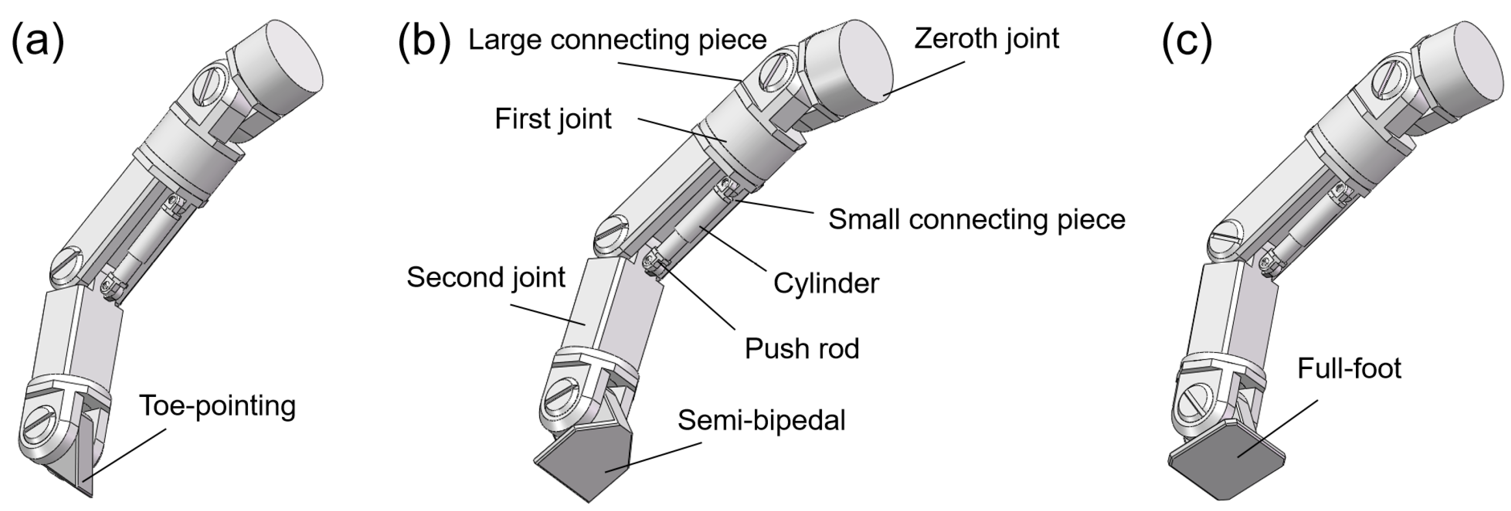
The 3D model of the bionic foot designed by the research team was constructed via parametric solid modeling techniques within the SolidWorks software environment, as illustrated in Figure 2. Initially, the core contour, critical structural dimensions, and interface configurations for connection to transmission components were precisely determined based on the kinematic performance requirements of the foot mechanism and actual loading conditions. During the modeling process, reference planes were established and sketches were drafted, followed by the application of feature operations including extrusion, cutting, and rotation to generate the preliminary geometric configuration of the foot body. The bionic foot was designed as a multi-component assembly structure: the toe and second joint segments, as the primary load-bearing structures during ground contact, were formed using the “Extrude” command, while the “Fillet/Chamfer” command was employed to optimize regions prone to stress concentration—this modification enhances structural strength and fatigue life, ensuring stability during grasping operations. Finally, within the assembly environment, the “Mate” command was utilized to accurately define the relative positions and motion relationships of each component. After a comprehensive “Interference Check” confirmed the absence of design conflicts, the integrated 3D model was exported in the universal STEP format, providing foundational model data for subsequent in-depth research such as finite element analysis (FEA).

2.3.2. Ansys Meshing

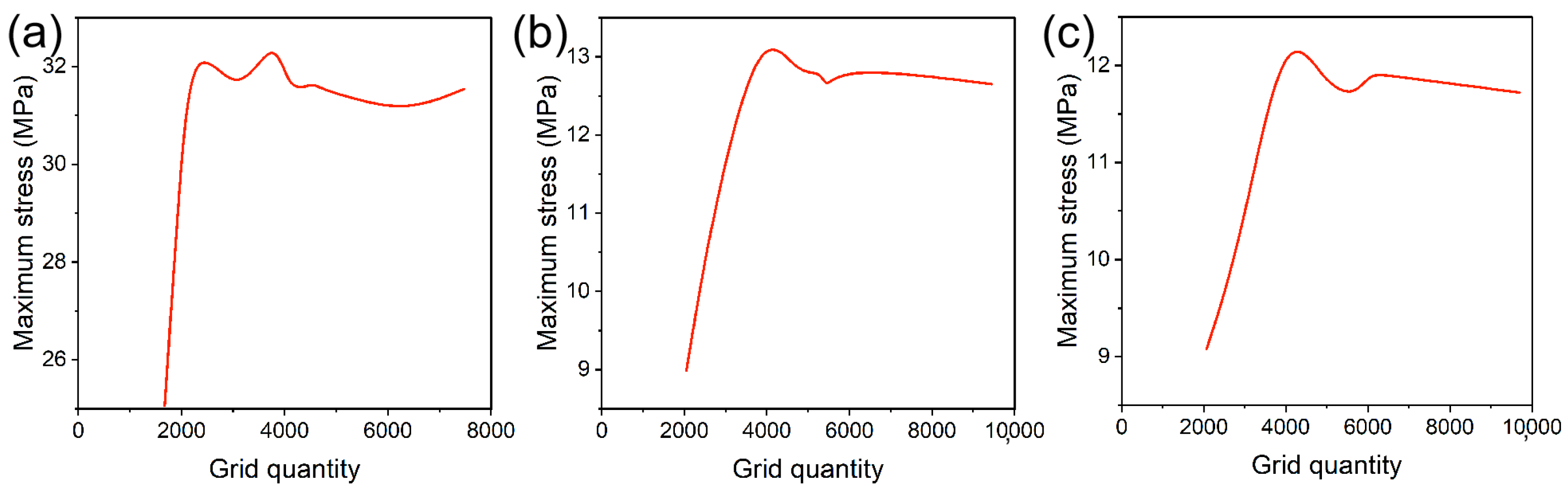
To ensure both high accuracy and computational efficiency of simulation analysis under complex working conditions, a hybrid meshing strategy was implemented for the integrated bionic foot model within the Ansys Workbench environment. The global element size was uniformly set to 1.0 mm. Specifically, for structurally regular main components (e.g., the foot body and joints), the hexahedral-dominant (Hex Dominant) meshing method was prioritized, given its superior computational efficiency. For critical components with complex geometries—including the stainless steel bionic foot and its transmission joints—tetrahedral (Tetrahedral) elements were employed to accommodate their structural irregularities. Local mesh refinement was further applied to contact regions via local sizing control to precisely capture localized stress and strain characteristics. Additionally, to ensure computational accuracy, contact mesh refinement was specifically implemented for contact pairs involving relative motion. The final finite element model not only accurately captures structural stress distribution and deformation but also achieves rational control over computational resource consumption. Mesh independence verification aims to confirm that simulation results converge to stability across varying mesh densities, ensuring solution accuracy is independent of mesh refinement levels. Initial calculations were performed using coarse meshes, followed by progressive mesh refinement while monitoring variations in the maximum stress values. As illustrated in Figure 3 and Table 1, no significant changes in key results were observed with increasing mesh density, indicating that the selected mesh size is reasonable and the solution has reached mesh independence.

3. Results and Discussion

3.1. Finite Element Analysis of the Bionic Foot

3.1.1. Stress Distribution Characteristics of the Bionic Foot

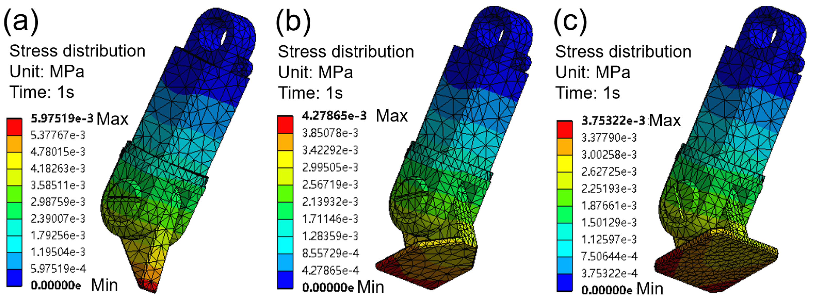
In this study, to accurately simulate the tribological behavior and force-bearing characteristics of the bionic foot, appropriate boundary conditions and external loads were defined in accordance with its operating conditions and geometric features. The root of the bionic foot was fully constrained to eliminate model drift or unconstrained motion during computation. Additionally, contact interactions at the contact interface were specified based on the actual contact configuration of the bionic foot. To replicate the real-world loading conditions during the grasping process, external loads were applied to the surface of the bionic foot. The operational process of the bionic foot is a dynamic process. During the motion of the three bionic foot configurations, the driving forces exerted by the actuator at the drive point are comparable; however, due to variations in the foot’s structural geometry, the forces transmitted to the contact interface differ significantly. As illustrated in the stress distribution maps of the bionic foot (Figure 4), when the foot is in contact with the ground, the tip-based foot sole exhibits the highest stress (Figure 4a), while the full-foot sole exhibits the lowest stress (Figure 4c). Furthermore, the maximum stress in the actuation mechanism of the bionic foot is concentrated at either the toe or the mid-section of the foot body.

3.1.2. Deformation Characteristics of the Bionic Foot

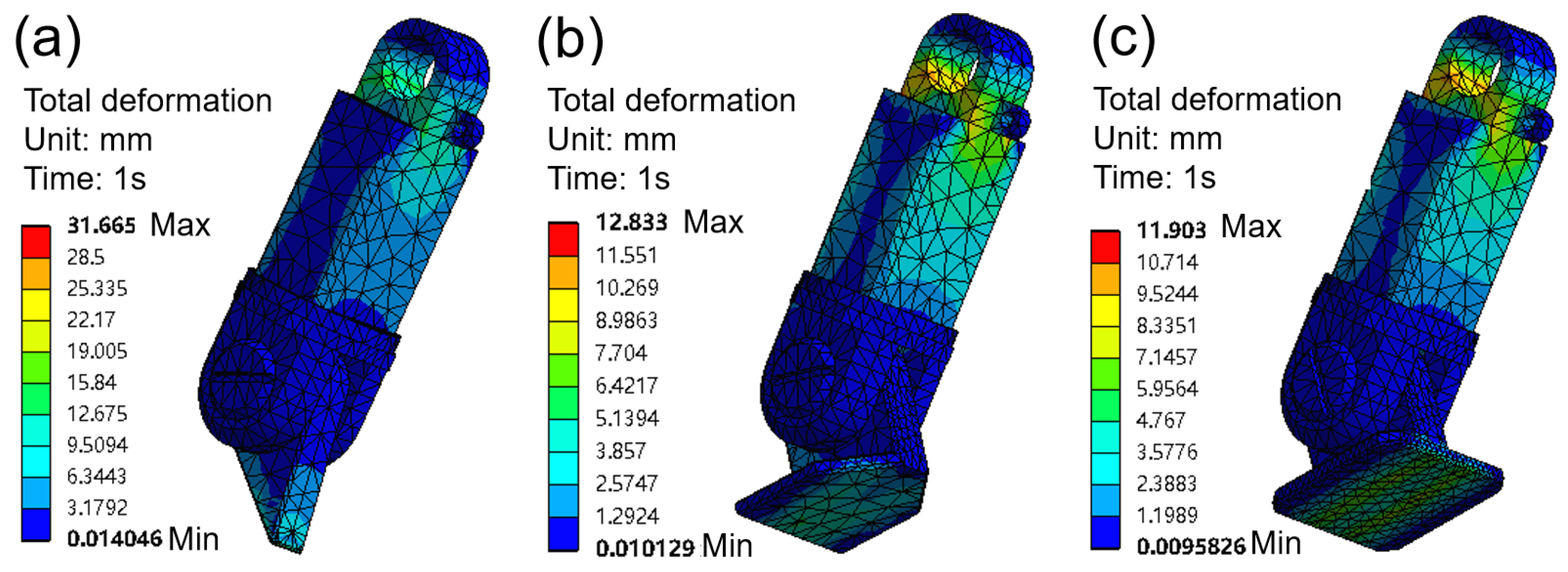
From the total deformation map of the bionic foot (Figure 5), it is evident that during ground contact, deformation is primarily concentrated at the toe tip, as well as the edges and corners of the foot body. Throughout each contact working cycle, the stress on the bionic foot undergoes a low-to-high-to-low variation, forming an alternating stress cycle [26,27]. Stainless steel materials undergo failure after a sufficient number of cycles under alternating stress levels far below their static strength limit; deformation or crack initiation typically occurs at stress concentration regions.

3.2. Tribological Behavior

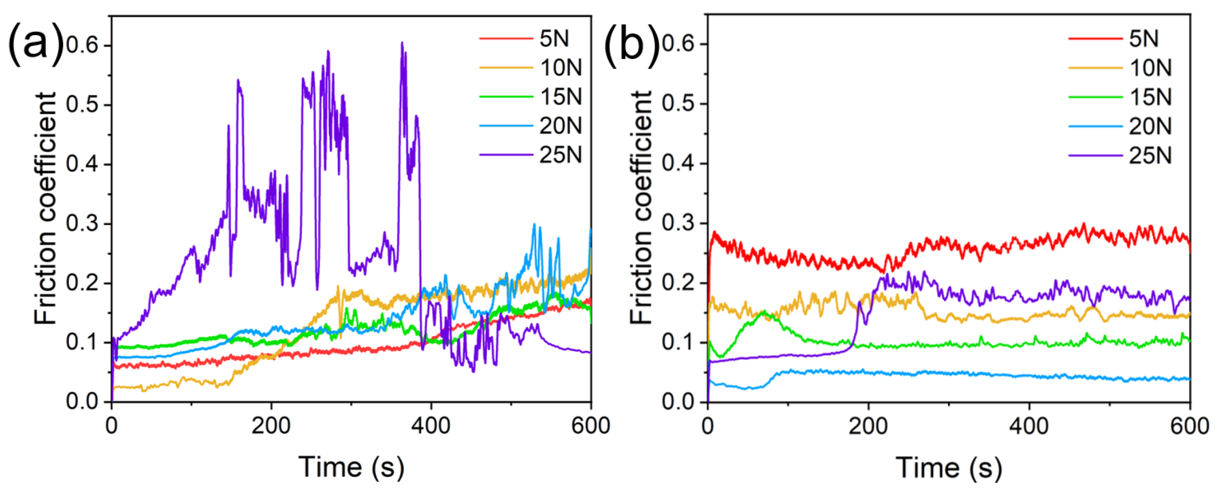
Through modeling the surface contact mechanics of the bionic foot, it was confirmed that deformation is predominantly localized at the toe tip and the edges/corners of the foot. Accordingly, a cellulose coating was applied to the surface of the bionic foot (i.e., the 304 stainless steel surface) to enhance its lubrication performance. For the uncoated sample (Figure 6a), the friction coefficient increases with increasing load, rising from 0.11 to 0.32; when the load reaches 25 N, the amplitude of friction coefficient variation increases sharply. This phenomenon may be attributed to the presence of burrs on the contact surfaces of the upper and lower specimens, which exacerbate friction instability. Additionally, the relatively low mass of the experimental apparatus induces vibrations during rotation, compromising loading stability and thus leading to significant temporal fluctuations in the friction coefficient. For the cellulose-coated sample (Figure 6b), the friction coefficient exhibits a trend of initial decrease followed by increase, dropping from 0.26 to 0.04 before rising to 0.18, with notably smaller fluctuations. At 5 N normal loads, the cellulose-coated specimen exhibits a higher friction coefficient than the uncoated counterpart, which can be attributed to the synergistic effects of adhesion induced by its high surface energy (hydroxyl-rich surface), rough surface topography, and distinct contact mechanical behaviors under low-load conditions. At loads below 25 N, the cellulose on the specimen surface acts as a lubricant, resulting in a lower friction coefficient. However, as the load increases, a large number of cellulose particles are extruded from the contact interface under rotational motion, weakening the lubricating effect of cellulose and consequently causing an increase in the friction coefficient. This also represents a typical characteristic of three-body wear. Additionally, the cellulose at the contact interface undergoes further deformation and damage under the induction of high-load friction, which in turn affects the friction coefficient [28].
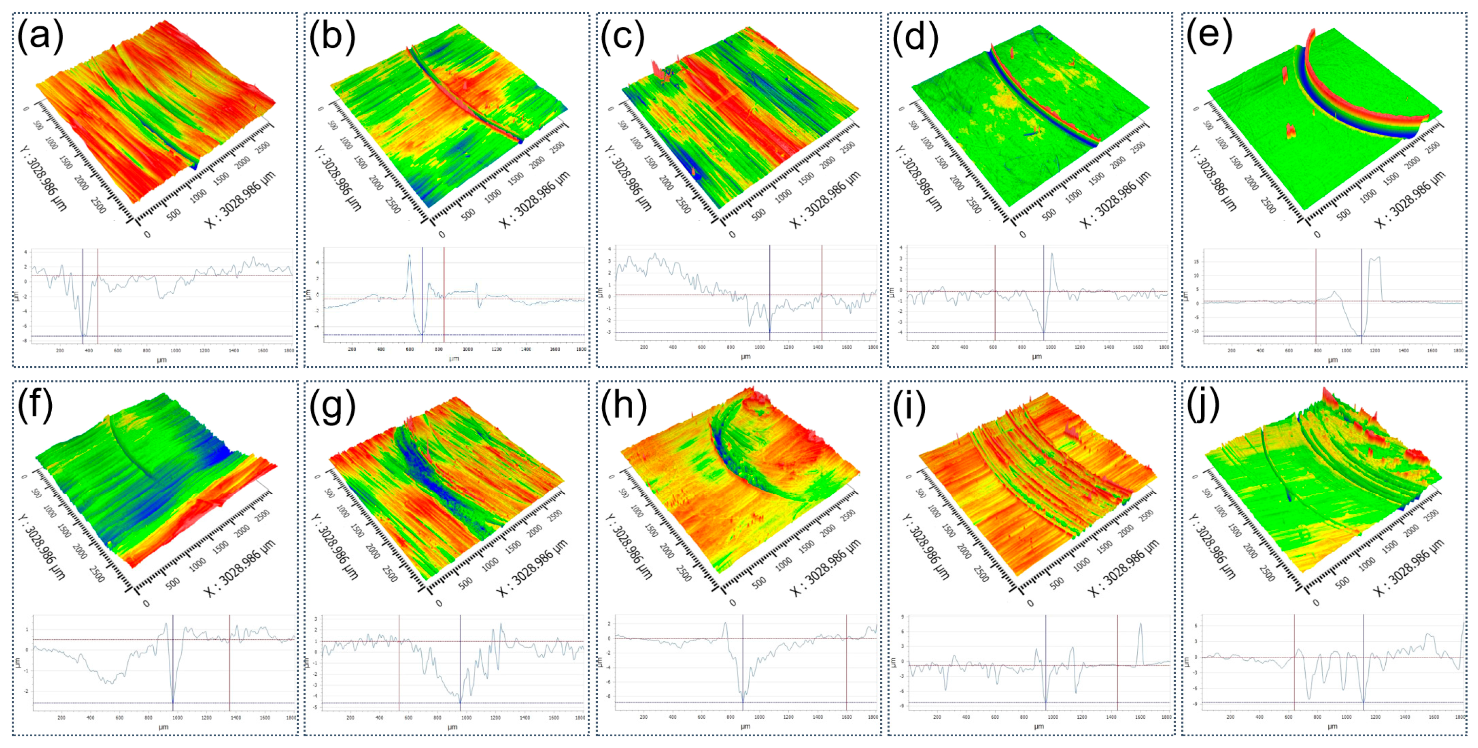
In tribological characterization, surface microtopography—including height distribution, roughness parameters, and texture anisotropy—is quantitatively assessed using a 3D white-light interferometric profilometer. Comparative analysis of topographical data across representative specimens provides mechanistic insight into friction evolution and wear mechanisms, thereby enabling rigorous evaluation of wear resistance and functional integrity of the tribological interface. Figure 7 presents the volumetric wear loss of the 304 stainless steel sheets, reconstructed from 3D white-light interferometric morphology measurements. From Figure 7a, the wear scar depths are measured as 8.1 μm, 4.9 μm, 3.2 μm, 3.9 μm, and 12.5 μm in sequence. With increasing normal load, the wear scar depth exhibits a trend of initial decrease followed by increase, which aligns with the variation pattern of the friction coefficient. Macroscopically, the contact between the upper and lower specimens occurs at their flat interfaces; microscopically, however, it is governed by direct interactions between surface micro-asperities. As the load increases, the contact pressure between micro-asperities gradually rises, leading to a reduction in wear scar depth. When the load reaches 25 N, the wear scar depth increases abruptly—this phenomenon is likely attributed to a transition in the frictional contact regime, which induces a sharp increase in wear scar width. From Figure 7b, the wear scar depths are 3.1 μm, 5.6 μm, 8.8 μm, 7.4 μm, and 8.7 μm, respectively. Similarly to the uncoated specimen, the wear scar depth of the cellulose-coated sample follows an initial decrease then increase with increasing load, consistent with the friction coefficient variation. Notably, the minimum wear scar depth occurs at 20 N. This observation suggests that cellulose treatment introduces numerous gaps at the micro-asperity contact interface: at low loads, the gaps are sufficiently large to prevent full participation of cellulose particles in the frictional process. As friction proceeds, surface peaks on both specimens gradually undergo plastic deformation (collapsing) or wear flattening, which reduces the volume of the gaps. This forces more cellulose particles to enter the contact interface, exerting a pronounced anti-wear effect and thus decreasing the wear scar depth.

3.3. Surface Morphology

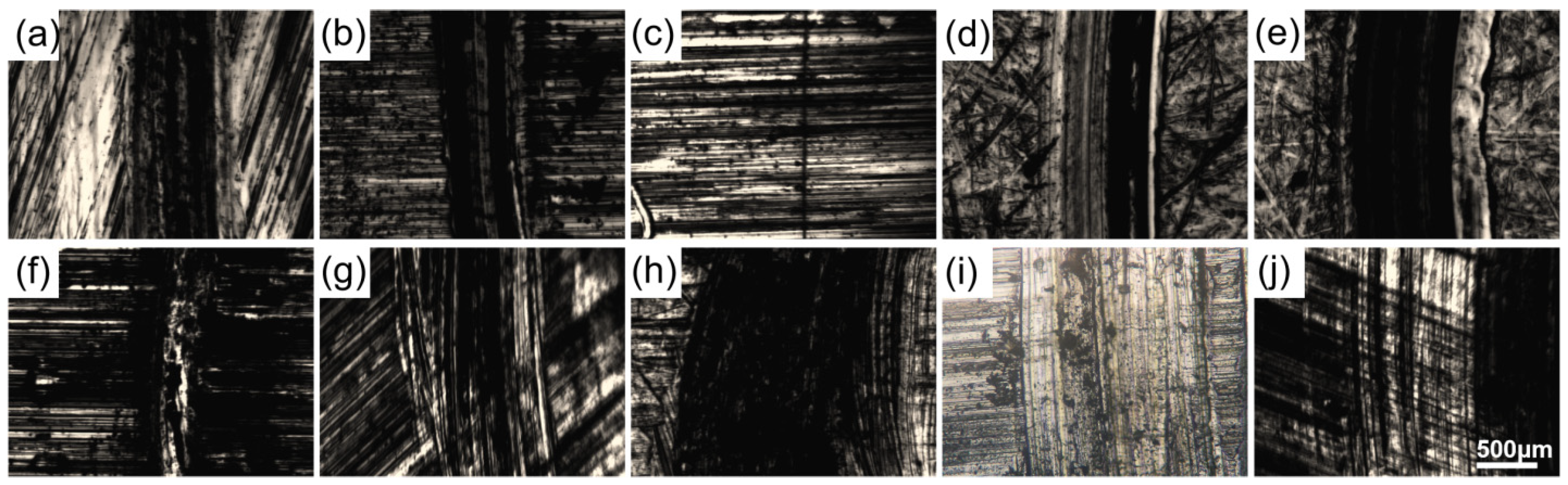
Optical microscopy and Raman spectroscopy are complementary, high-resolution analytical techniques widely employed in tribological surface characterization. Optical microscopy enables direct visualization—either in situ or post-test—of contact geometry, wear track morphology, and surface damage evolution, thereby elucidating interfacial interaction mechanisms under sliding conditions. Raman spectroscopy provides molecular-level information on chemical composition, phase distribution, and crystallinity within the near-surface region (typically <1 μm depth), while also enabling identification of tribochemical reaction products such as oxides, carbides, or organic decomposition species. Their synergistic application facilitates correlative structural–chemical analysis of the friction interface, significantly advancing mechanistic understanding of wear mechanisms and lubrication performance. Figure 8 presents representative optical micrographs of the worn surfaces of the 304 stainless steel sheets. From Figure 8a, as the load increases, the wear scar width initially decreases and then increases. This may be because, under extremely low loads, the friction pair may be in a micro-asperity contact state with a very small actual contact area. As the load increases, these micro-asperities are rapidly flattened, leading to better conformity of contact and more uniform stress distribution, which reduces the wear depth and consequently narrows the wear scar width. However, when the load exceeds 15 N, the contact mode shifts from elastic to extensive plastic contact, causing severe plastic flow and plowing effects, resulting in a sharp increase in wear scar width. From Figure 8b, after cellulose treatment, the wear scar width also increases with increasing load. At lower loads, cellulose may reduce friction through a rolling effect. However, at higher loads, crushed cellulose fragments may embed into the surface of the wear scar. These hard cellulose fragments can act as abrasive particles during friction, participating in micro-cutting processes and thereby widening the wear scar [29]. Compared to untreated samples, the wear scar width is larger due to the fact that cellulose particles or fibers are not perfect spherical rollers but rather rod-like structures [21]. Under load, these irregularly shaped protrusions generate extremely high local contact stresses on the stainless steel surface [29,30]. Such stress concentrations lead to deeper plastic deformation layers, microcracks, and dislocation pile-ups beneath the surface. When this subsurface damage accumulates to a certain extent, it promotes large-scale material delamination, resulting in wider wear scars.
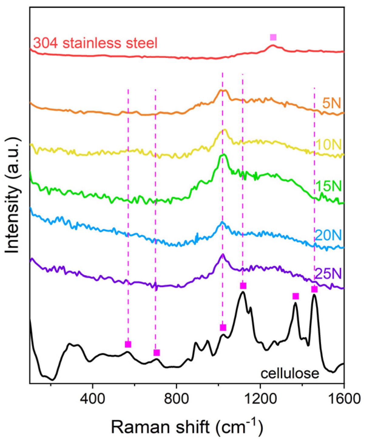
Figure 9 presents the Raman spectra of 304 stainless steel sheets. The characteristic Raman peak of 304 stainless steel is located at 1257 cm−1, while the signature peaks of cellulose are observed at 571, 705, 1019, 1117, 1367, and 1462 cm−1. For the cellulose-treated specimens, the Raman spectrum acquired from the wear scar reveals a characteristic peak of 304 stainless steel at 1285 cm−1. The primary mechanism underlying this peak shift is twofold: first, cellulose, as a polymeric material, undergoes volume expansion/contraction under laser irradiation; upon contact with the metal substrate, this volume change imposes lattice stress on the stainless steel, altering the position of its characteristic Raman peaks and inducing significant displacement [31]. Second, cellulose contains abundant hydroxyl (–OH) groups, which form friction-induced chemical bonds with iron atoms on the stainless steel surface. These newly formed bonds disrupt the original metallic bonding configuration, leading to shifts in the vibrational frequencies of the stainless steel’s Raman peaks [32]. Additionally, peaks matching the characteristic features of cellulose are detected at 562, 700, 1112, and 1459 cm−1. These results confirm that the wear scars on the cellulose-treated 304 stainless steel surface contain both 304 stainless steel wear debris and fragmented cellulose fibers.

3.4. Lubrication Mechanism

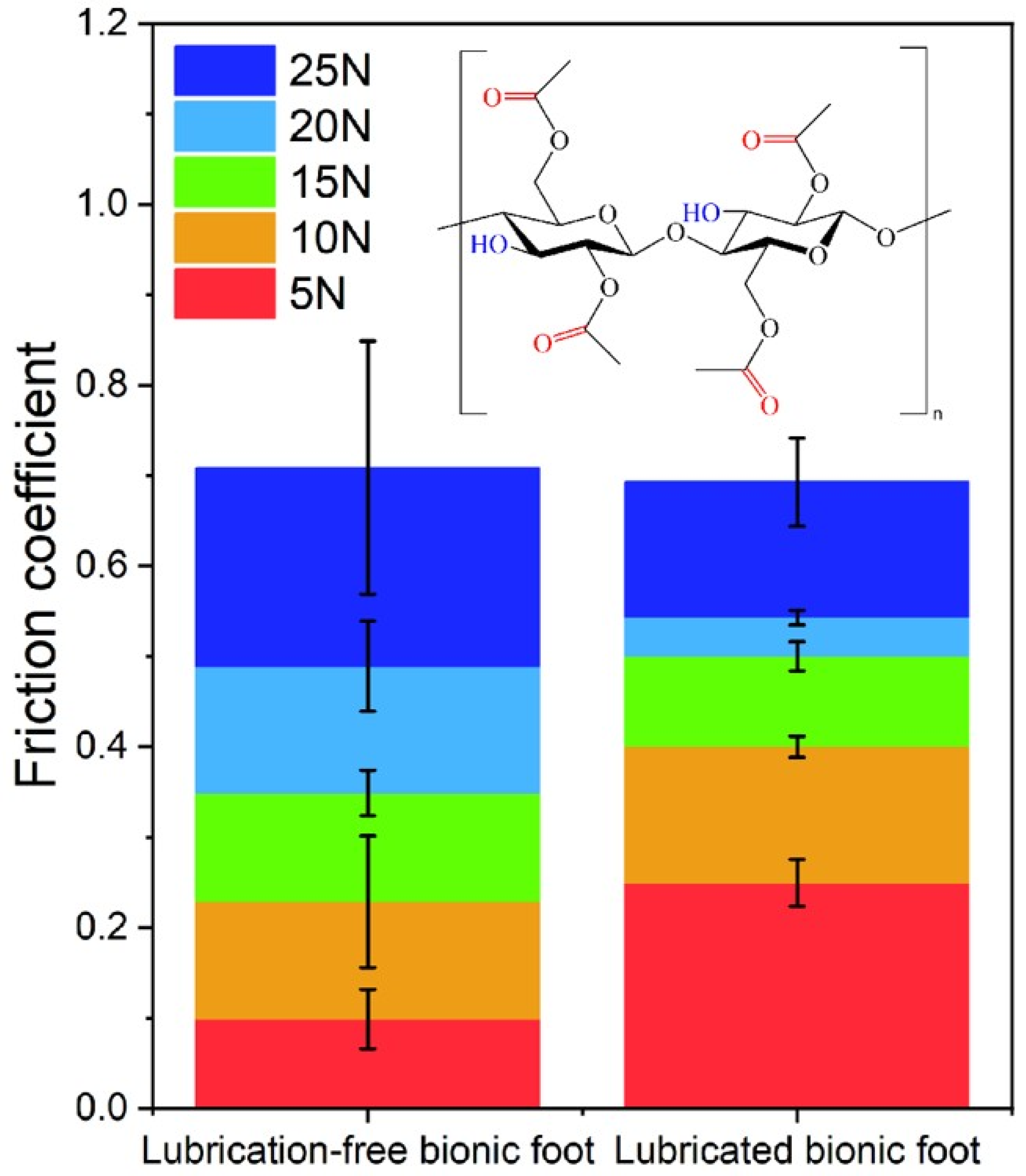
Figure 10 presents a comparison of the average friction coefficients of the bionic foot surface before and after modification, alongside the molecular structure of cellulose. As illustrated in Figure 10, the friction coefficient of the stainless steel substrate generally exhibits an upward trend with increasing normal load. For the cellulose-coated specimens, the friction coefficient decreases significantly when the load exceeds 10 N. The underlying mechanism for this phenomenon lies in the abundant polar methoxy functional groups within the cellulose molecular structure. During sliding, these functional groups form a lubricating protective film at the contact interface via a combination of physical adsorption (van der Waals forces) and chemical adsorption (coordination bonds with surface metal atoms). This film effectively mitigates direct contact between surface micro-asperities of the stainless steel, thereby substantially enhancing its tribological performance. Furthermore, under higher loads, the elevated contact pressure and frictional temperature in the sliding zone promote more intimate adsorption and ordered alignment of cellulose molecules on the stainless steel surface, yielding a denser and mechanically robust boundary lubrication film. Concurrently, frictional heat may increase the flexibility of cellulose molecular chains, facilitating the formation of a low-shear-strength slip layer under shear stress and thus sustaining stable lubrication. However, this beneficial effect is constrained by a critical load threshold—beyond this limit, mechanical disruption (e.g., film delamination, abrasive wear) dominates the failure of the lubrication film.
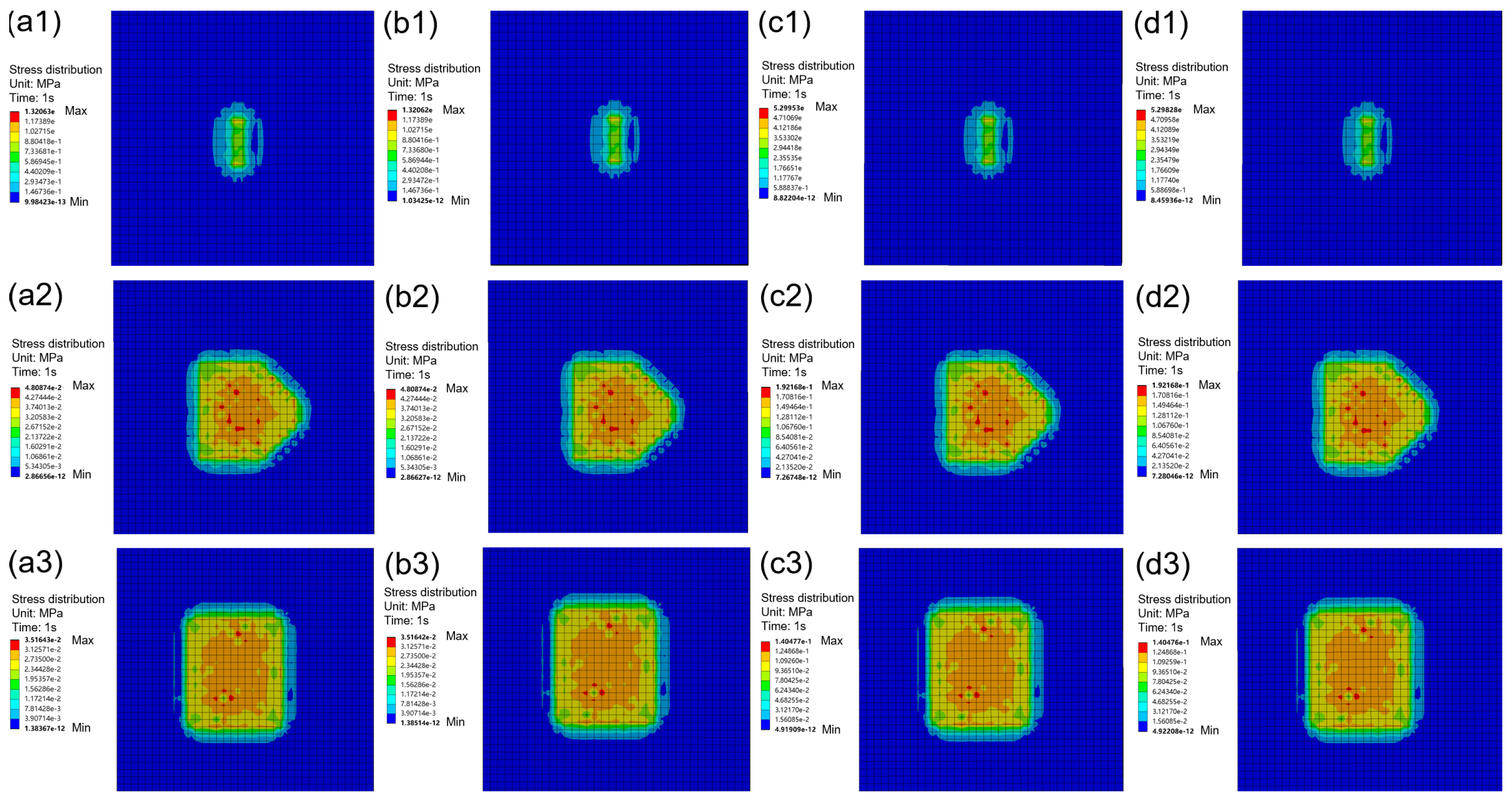
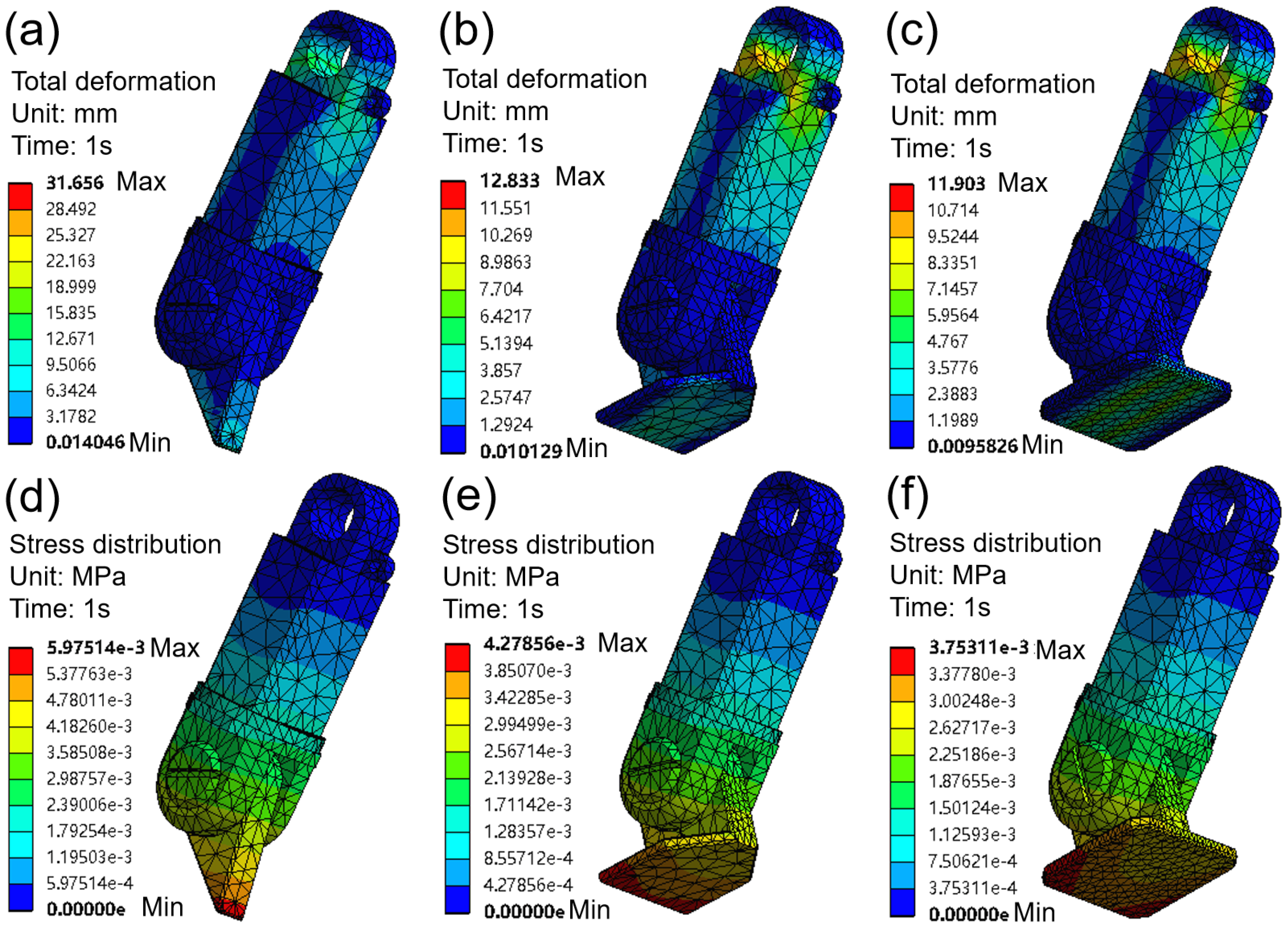
The static contact stress and friction dynamics contour maps of the lubrication-treated stainless steel bionic foot are depicted in Figure 11 and Figure 12, respectively. For the unlubricated bionic foot, the stress distribution is relatively uniform, with the maximum stress concentrated predominantly on the surface. After lubrication treatment, residual stresses pre-existing on the surface partially counteract the applied working tensile stresses; however, stress concentration hotspots persist at the toe (Figure 11a) and the mid-foot region (Figure 11a,b). Concurrently, the location of maximum stress shifts from the surface to the subsurface layer or the lubricant–substrate interface. Additionally, the total deformation of the stainless steel bionic foot remains essentially unchanged following lubrication treatment (Figure 11d–f). As illustrated in Figure 12, the sole surfaces of the three bionic feet undergo varying degrees of deformation during their interaction with the contact ground. For the toe-pointing type, friction is primarily concentrated in the contact edge region. In the cases of the semi-bipedal type and full-foot type, friction is mainly localized in the central region. Regardless of whether the normal load is low (5 N) or high (20 N), the position of the friction source remains essentially unchanged; after lubrication treatment, the area of the friction source is slightly reduced.
Comprehensive tribological testing demonstrates that under high normal loads (≥15 N), the friction coefficient reduction induced by cellulose lubrication becomes significantly more pronounced. This behavior stems from two core mechanisms: First, the cellulose molecular structure is rich in hydroxyl (–OH) functional groups [33,34]. During sliding contact, these polar groups form a lubricating protective film at the interface via synergistic physical (van der Waals forces) and chemical (coordination bonding with surface Fe atoms) adsorption. This film effectively mitigates direct contact between surface micro-asperities of the stainless steel substrate, thereby substantially enhancing its tribological performance. Second, elevated contact pressure and frictional temperature under high loads facilitate tighter adsorption and ordered alignment of cellulose molecules on the stainless steel surface, yielding a denser and mechanically robust boundary lubrication film. Concurrently, frictional heat increases the flexibility of cellulose molecular chains, promoting the formation of a low-shear-strength slip layer under shear stress and thus sustaining stable lubrication [34,35]. Complementary analysis of optical microscopy and 3D white-light interferometry images of wear scars from untreated specimens reveals metal spallation caused by cutting (abrasive scoring) and plowing grooves, indicating that adhesive and abrasive wear dominate the wear mechanism of unmodified 304 stainless steel. After cellulose treatment, plowing and delamination on the wear scar surface are significantly reduced, with no visible black residues—confirming that cellulose effectively isolates direct contact between the friction pairs and achieves superior surface lubrication. Raman spectroscopy results further validate that cellulose forms friction-induced tribofilms that cover the wear scar surface during sliding, thereby exerting a lubricating effect. Thus, the lubrication mechanism of cellulose on the bionic foot surface is identified as transfer-film lubrication.

4. Conclusions

This study integrates finite element analysis using Ansys software with face-to-face tribological testing of 304 stainless steel under systematically varied normal loads to comprehensively investigate the surface mechanical behavior and lubrication performance of three distinct metallic bionic foot designs. Results reveal that the maximum von Mises stress is predominantly localized at the toe and mid-foot regions, whereas primary plastic deformation occurs at the toe and contact edges. Although lubrication slightly reduces the extent of the frictional contact zone, it does not alter the fundamental stress–deformation distribution patterns. Furthermore, cellulose-based surface treatment enables the formation of a robust tribofilm through combined physical adsorption and chemical bonding, effectively preventing direct metal–metal contact and thereby suppressing delamination and plastic deformation. Notably, under elevated loads, friction-induced thermal energy enhances the conformational mobility of cellulose chains, facilitating the in situ formation of a low-shear-strength interfacial slip layer—contributing critically to sustained lubrication stability.
Limitations: First, tribological tests used idealized face-to-face contact and varied only normal load—ignoring temperature and humidity effects on cellulose lubricant film stability and durability. Second, finite element analysis modeled only static or quasi-static stress, omitting dynamic impact loads and fatigue accumulation across gait cycles.
Future research directions: First, uncover how cellulose lubricant films adapt to combined temperature and humidity changes. Second, develop a time-varying model linking dynamic loading and wear accumulation—integrating finite element analysis and fatigue theory to predict bionic foot wear over its full service life.
This study develops a physics-based mechanical model for the metallic bionic foot and validates it against friction and wear data from representative service conditions. The model accurately predicts contact stress distribution and wear progression over time. Based on this model, three key design criteria are proposed: (i) controlled surface finishing to reduce asperity-level stress concentration; (ii) lubricant selection matched to load, speed, and temperature; and (iii) structural optimization to lower stress at contact edges. Applying these criteria slows wear and extends functional service life.

Author Contributions

The manuscript was written through the contributions of all authors. X.Y. and H.P. wrote the original draft. X.Y. and Q.H. performed the experiments and collected the data. X.Y. and H.P. confirmed the final draft. D.L. conceived the conceptualization. All authors have read and agreed to the published version of the manuscript.

Funding

This work was supported by the Ministry of Education Fund.

Data Availability Statement

Data available in a publicly accessible repository.

Conflicts of Interest

The authors declare no conflicts of interest.

References

  1. Tu, Y.; He, Y.; Zhang, L.; Song, M. Low friction and wear characteristics formed by mechanically induced surface nanocrystallization: A review of recent advances. Friction 2025, 13, 9440971. [Google Scholar] [CrossRef] [Scilit]
  2. Fu, L.; Gu, H.; Huang, A.; Or, S.W.; Zou, Y.; Zou, Y.; Zhang, M. Design, fabrication and properties of lightweight wear lining refractories: A review. J. Eur. Ceram. Soc. 2022, 42, 744–763. [Google Scholar] [CrossRef] [Scilit]
  3. Theerthagiri, J.; Senthil, R.A.; Senthilkumar, B.; Reddy Polu, A.; Madhavan, J.; Ashokkumar, M. Recent advances in MoS2 nanostructured materials for energy and environmental applications—A review. J. Solid State Chem. 2017, 252, 43–71. [Google Scholar] [CrossRef] [Scilit]
  4. Mosarof, M.H.; Kalam, M.A.; Masjuki, H.H.; Ashraful, A.M.; Rashed, M.M.; Imdadul, H.K.; Monirul, I.M. Implementation of palm biodiesel based on economic aspects, performance, emission, and wear characteristics. Energy Convers. Manag. 2015, 105, 617–629. [Google Scholar] [CrossRef] [Scilit]
  5. Zhao, W.; Li, S.; Zhang, K.; Zhang, W.; Liu, D.; Fang, W.; Zhai, Y.; Lei, K.; Zhang, L.; Chen, H.; et al. High-Speed, Maneuverable, and Terrain-Adaptive Micro-Robot with Tree Frog-Inspired Bionic Feet. Adv. Sci. 2025, 13, e14807. [Google Scholar] [CrossRef] [Scilit] [PubMed]
  6. Chen, G.; Zhao, Z.; Lu, Y.; Yang, C.; Hu, H. Deep reinforcement learning-based pitch attitude control of a beaver-like underwater robot. Ocean Eng. 2024, 307, 118163. [Google Scholar] [CrossRef] [Scilit]
  7. Zhu, X.; Zhao, Y.; Chi, Y.; Li, G.; Chen, X. Meshing principle and geometry of tooth profile for offset enveloping cylindrical worm drive. Mech. Mach. Theory 2023, 180, 105171. [Google Scholar] [CrossRef] [Scilit]
  8. Liang, Z.; He, P.; Zhao, Z.; Zhong, Y.; Li, Z.; Wang, M. Surface modification of 304 stainless steel by ultrasonic strengthening grind process with Al2O3-MoS2-WC hybrid ceramic particles for wear resistance enhancement. Surf. Coat. Technol. 2025, 515, 132687. [Google Scholar] [CrossRef] [Scilit]
  9. Pérez, H.; Vargas, G.; Magdaleno, C.; Silva, R. Article: Oxy-Nitriding AISI 304 Stainless Steel by Plasma Electrolytic Surface Saturation to Increase Wear Resistance. Metals 2023, 13, 309. [Google Scholar] [CrossRef] [Scilit]
  10. He, C.; Zou, G.; Liu, H.; Wang, X.; Xu, Y.; Liu, J.; Lo, S. Rolling–sliding wear and damage behaviors of 304L stainless steel laser cladding on a damaged wheel tread under high ambient temperature conditions. Wear 2024, 546–547, 205330. [Google Scholar] [CrossRef] [Scilit]
  11. Liu, Z.; Luo, L.; Zhang, Z.; Song, S. Preparation of Ti–MoS2 coating and gradient structure via mechanical ball milling to improve the wear resistance of AISI 440C stainless steel bearing balls. Vacuum 2024, 227, 113426. [Google Scholar] [CrossRef] [Scilit]
  12. Funaro, A.; Shim, V.; Mylle, I.; Vong, C.; Vanwanseele, B. In vivo-driven optimization of finite element models’ parameters for capturing altered mechanics in patients with Achilles tendinopathy. J. Biomech. 2025, 189, 112824. [Google Scholar] [CrossRef] [Scilit] [PubMed]
  13. Gu, Y.; Yuan, Y.; Xue, K.; Yin, Y.; Lu, S.; Jiang, X. A Novel Strength Reduction Method for a Slope Stability Assessment Based on a Finite Element Method. Processes 2024, 12, 2273. [Google Scholar] [CrossRef] [Scilit]
  14. Yang, S.; Dong, H.; Zhang, Z.; Wang, Y.; Niu, X.; Lu, X. An enhancing flexibility piezoelectric stick-slip actuator by introducing perforation of flexible hinge. Sens. Actuators A Phys. 2024, 379, 115871. [Google Scholar] [CrossRef] [Scilit]
  15. Siqueira, T.M.; Coda, H.B. Flexible actuator finite element applied to spatial mechanisms by a finite deformation dynamic formulation. Comput. Mech. 2019, 64, 1517–1535. [Google Scholar] [CrossRef] [Scilit]
  16. Pavanello, P.; Carrubba, P.; Moraci, N. The characterisation of geosynthetic interface friction by means of the inclined plane test. Geotext. Geomembr. 2021, 49, 257–275. [Google Scholar] [CrossRef] [Scilit]
  17. Basseville, S.; Niass, M.; Missoum-Benziane, D.; Leroux, J.; Cailletaud, G. Effect of fretting wear on crack initiation for cylinder-plate and punch-plane tests. Wear 2019, 420–421, 133–148. [Google Scholar] [CrossRef] [Scilit]
  18. Brown, R.M. Cellulose structure and biosynthesis: What is in store for the 21st century? J. Polym. Sci. Part A Polym. Chem. 2004, 42, 487–495. [Google Scholar] [CrossRef] [Scilit]
  19. Cao, S.; Wang, J.; Wang, Q.; Han, S.; Wang, C. Application and prospect of cellulose in tribology. Mater. Today Commun. 2025, 49, 114342. [Google Scholar] [CrossRef] [Scilit]
  20. Greene, G.W.; Olszewska, A.; Osterberg, M.; Zhu, H.; Horn, R. A cartilage-inspired lubrication system. Soft Matter 2014, 10, 374–382. [Google Scholar] [CrossRef] [Scilit] [PubMed]
  21. Pang, H.; Xu, J.; Liu, H.; Wang, W.; Yin, X.; Liu, D.; Zhang, B. The Induced Orientation of Hydroxypropyl Methylcellulose Coating for Ultralow Wear. Lubricants 2024, 12, 129. [Google Scholar] [CrossRef] [Scilit]
  22. Yin, X.; Pang, H.; Yang, Y.; Hu, C.; Zhang, B. The Invention Discloses a Wear-Resistant Cellulose Coating and a Preparation Method Thereof. China ZL202310571536.8, 21 May 2023. [Google Scholar]
  23. Yin, X.; Zhang, D.; Li, L.; Zhang, B. The Influence of Length-Diameter Ratio of Cellulose on Friction Characteristics of Screw Surface Investigated by EDEM Simulation. Macromol. Theory Simul. 2024, 34, 2400083. [Google Scholar] [CrossRef] [Scilit]
  24. Siqi, W.; Nishimoto, M.; Muto, I. Machined Surface Characteristics and MnS Inclusions as Key Factors in Early-Stage Pitting Corrosion of 304 Stainless Steel. ECS Meet. Abstr. 2025, MA2025-02, 1152. [Google Scholar] [CrossRef] [Scilit]
  25. Liu, X.; Zhang, H.; Tong, H.; Sui, Y.; Li, X.; Hou, J. Effect of Surface Roughness on the Corrosion Behavior of 304 Stainless Steel in Seawater. J. Mater. Eng. Perform. 2024, 34, 18287–18297. [Google Scholar] [CrossRef] [Scilit]
  26. Zaidi, L.; Corrales, J.A.; Bouzgarrou, B.C.; Mezouar, Y.; Sabourin, L. Model-based strategy for grasping3Ddeformable objects using a multi-fingered robotic hand. Robot. Auton. Syst. 2017, 95, 196–206. [Google Scholar] [CrossRef] [Scilit]
  27. Lin, Q.; Burdick, J.W.; Rimon, E. Computation and Analysis of Natural Compliance in Fixturing and Grasping Arrangements. IEEE Trans. Robot. 2004, 20, 651–667. [Google Scholar] [CrossRef]
  28. Okubo, H.; Nakae, R.; Iba, D.; Yamada, K.; Hashiba, H.; Nakano, K.; Sato, K.; Sasaki, S. Tribological properties of 100% cellulose nanofiber (CNF) molding under dry- and boundary lubrication-conditions at CNF/steel contacts. Cellulose 2023, 30, 6887–6905. [Google Scholar] [CrossRef] [Scilit]
  29. Ciesielski, P.N.; Wagner, R.; Bharadwaj, V.S.; Killgore, J.; Mittal, A.; Beckham, G.T.; Decker, S.R.; Himmel, M.E.; Crowley, M.F. Nanomechanics of cellulose deformation reveal molecular defects that facilitate natural deconstruction. Proc. Natl. Acad. Sci. USA 2019, 116, 9825–9830. [Google Scholar] [CrossRef] [Scilit] [PubMed]
  30. Quereilhac, D.; De Luycker, E.; Magueresse, A.; Guessasma, S.; Weitkamp, T.; Scheel, M.; Bourmaud, A.; Abida, M.; Kozlova, L.; Ouagne, P. Understanding longitudinal defects in flax fibres for bio-based composites: Structure, mechanical impact and possible origins. Compos. Part A Appl. Sci. Manuf. 2025, 199, 109220. [Google Scholar] [CrossRef] [Scilit]
  31. Abiko, K.; Kato, Y.; Hohjo, H.; Kishida, Y.; Sudo, E. Raman imaging of residual stress distribution in epoxy resin and metal interface. J. Raman Spectrosc. 2019, 51, 193–200. [Google Scholar] [CrossRef] [Scilit]
  32. Ho, W.K.H.; Bao, Z.Y.; Gan, X.; Wong, K.-Y.; Dai, J.; Lei, D. Probing Conformation Change and Binding Mode of Metal Ion–Carboxyl Coordination Complex through Resonant Surface-Enhanced Raman Spectroscopy and Density Functional Theory. J. Phys. Chem. Lett. 2019, 10, 4692–4698. [Google Scholar] [CrossRef] [Scilit] [PubMed]
  33. Rahmadiawan, D.; Shi, S.-C.; Aslfattahi, N.; Fauza, A.N.; Fuadi, Z. Advancements in Cellulose for Eco-Friendly Lubricant Applications: A Review on Tribological Properties. ACS Omega 2025, 10, 36878–36889. [Google Scholar] [CrossRef] [Scilit] [PubMed]
  34. Okubo, H.; Hashiba, H.; Inamochi, T.; Sato, K.; Sasaki, S.; Yamada, K.; Nakano, K. Novel Environmentally Superior Tribomaterial with Superlow Friction: 100% Cellulose Nanofiber Molding. Tribol. Lett. 2023, 71, 83. [Google Scholar] [CrossRef] [Scilit]
  35. Okubo, H.; Ishikawa, T.; Hashiba, H.; Inamochi, T.; Nakano, K. In-situ vibrational spectroscopic observation for thermally activated structural changes of 100% cellulose nanofiber molding with ultralow friction. Front. Mech. Eng. 2024, 10, 1422412. [Google Scholar] [CrossRef] [Scilit]
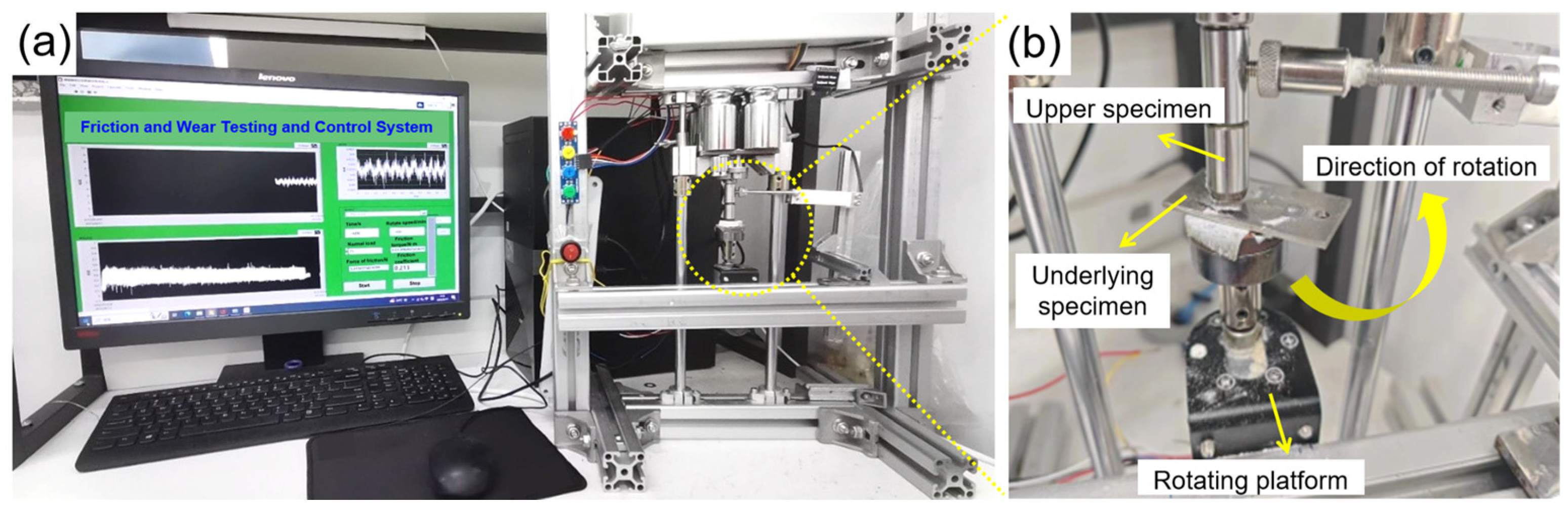
Figure 1. (a) Schematic illustration of the face-to-face friction testing system; (b) magnified view of the contact region.
Lubricants 14 00317 g001
Figure 2. 3D schematic representations of the bionic foot configurations. (a) Toe-pointing type. (b) Semi-bipedal type. (c) Full-foot type.
Lubricants 14 00317 g002
Figure 3. Mesh independence verification: variation in maximum von Mises stress with mesh density. (a) Toe-pointing type. (b) Semi-bipedal type. (c) Full-foot type.
Lubricants 14 00317 g003
Figure 4. Stress distribution characteristics of the bionic foot under ground contact conditions. (a) Toe-pointing type. (b) Semi-bipedal type. (c) Full-foot type.
Lubricants 14 00317 g004
Figure 5. Total deformation characteristics of the bionic foot during ground contact. (a) Toe-pointing type. (b) Semi-bipedal type. (c) Full-foot type.
Lubricants 14 00317 g005
Figure 6. Tribological response of 304 stainless steel sheets under varying normal loads. (a) Uncoated. (b) Cellulose-coated.
Lubricants 14 00317 g006
Figure 7. Volumetric wear loss of 304 stainless steel sheets under varying normal loads. (ae) Volumetric wear loss of 304 stainless steel sheets under varying normal loads. (fj) Cellulose-coated specimens. (a,f) 5 N; (b,g) 10 N; (c,h) 15 N; (d,i) 20 N; (e,j) 25 N.
Lubricants 14 00317 g007
Figure 8. Surface morphology of 304 stainless steel sheets tested under varying normal loads. (ae) Uncoated specimens. (fj) Cellulose-coated specimens. (a,f) 5 N; (b,g) 10 N; (c,h) 15 N; (d,i) 20 N; (e,j) 25 N.
Lubricants 14 00317 g008
Figure 9. Raman spectra of 304 stainless steel sheets tested under varying normal loads and after cellulose treatment.
Lubricants 14 00317 g009
Figure 10. Average friction coefficient of the bionic foot surface before and after cellulose coating, alongside the molecular structure of cellulose.
Lubricants 14 00317 g010
Figure 11. Static contact stress diagram of the stainless steel bionic foot after lubrication treatment. (ac) Stress distribution magnitude. (df) Total deformation magnitude. (a,d) Toe-pointing type. (b,e) Semi-bipedal type. (c,f) Full-foot type.
Lubricants 14 00317 g011
Figure 12. Friction dynamics contour maps of the stainless steel bionic foot before and after lubrication treatment. (a,b) 5N. (c,d) 20N. (a,c) Contact surface without cellulose coating. (b,d) Contact surface with cellulose coating. (a1,b1,c1,d1) Toe-pointing type. (a2,b2,c2,d2) Semi-bipedal type. (a3,b3,c3,d3) Full-foot type.
Lubricants 14 00317 g012
Table 1. Maximum stress and error for three types of bionic foot at different mesh counts.
Bionic Foot TypeGrid Size (mm)Number of Grids Maximum Stress (MPa)Error (Relative to 1.0 mm)
Toe-pointing type0.8640731.081.83%
0.9530531.341.00%
1.0453131.660.00%
1.1463431.350.97%
1.2406831.460.66%
Semi-bipedal type0.7944612.651.40%
0.9581212.890.46%
1.0531512.830.00%
1.15542112.572.02%
1.3473212.760.54%
0.7944612.651.40%
Full-foot type0.7970211.721.51%
0.9605011.920.16%
1.0644211.900.00%
1.15563811.662.01%
1.3489411.840.50%
Disclaimer/Publisher’s Note: The statements, opinions and data contained in all publications are solely those of the individual author(s) and contributor(s) and not of MDPI and/or the editor(s). MDPI and/or the editor(s) disclaim responsibility for any injury to people or property resulting from any ideas, methods, instructions or products referred to in the content.