1. Introduction
For rotating machinery, bearings serve a fundamental function in maintaining system stability, enhancing energy efficiency, and extending operational lifespan. Hydrodynamic journal bearings, relying on the relative motion of surfaces, generate a thin lubricant film in a wedge-shaped region. This film produces hydrostatic and hydrodynamic pressures that suspend the shaft, thereby preventing direct metal-to-metal contact and minimizing friction to the lowest possible level. In designing such components, key considerations include load-carrying capacity, minimum lubricant film thickness, and operational stability under temperature and speed variations.
Despite their high performance, the traditional use of petroleum-based lubricants has become increasingly controversial due to growing environmental concerns and the detrimental effects of oil leakage on aquatic ecosystems. Strict international regulations, such as the MARPOL Convention, have significantly accelerated the demand for environmentally friendly lubricants. In this context, water has emerged as an attractive alternative—being abundant, inexpensive, and inherently eco-compatible. This paradigm shift has consequently motivated the adoption of non-metallic bearing materials, particularly polymers and rubbers, which can safely operate under water or seawater lubrication.
Hydrodynamic rubber journal bearings lubricated with non-oil-based fluids such as water offer several advantages, including reduced operating and maintenance costs (due to the elimination of oils and expensive metallic alloys), enhanced environmental compatibility, extended service life through lower friction and wear, tolerance to suspended particles, and improved energy efficiency stemming from the low viscosity of water. Charles Frederick Sherwood pioneered the invention and patenting of the initial water-lubricated rubber bearing (WLRB) [
1]. One critical application of rubber bearings is in the stern tube of ships, where the grooves in these water-lubricated rubber bearings (WLRBs) are responsible for supplying lubricant, cooling the bearing environment, and expelling debris particles. The pressure between the two staves also bears the load. Proper installation, particularly precise alignment between the shaft and the bearing, is crucial to guarantee optimal long-term performance.
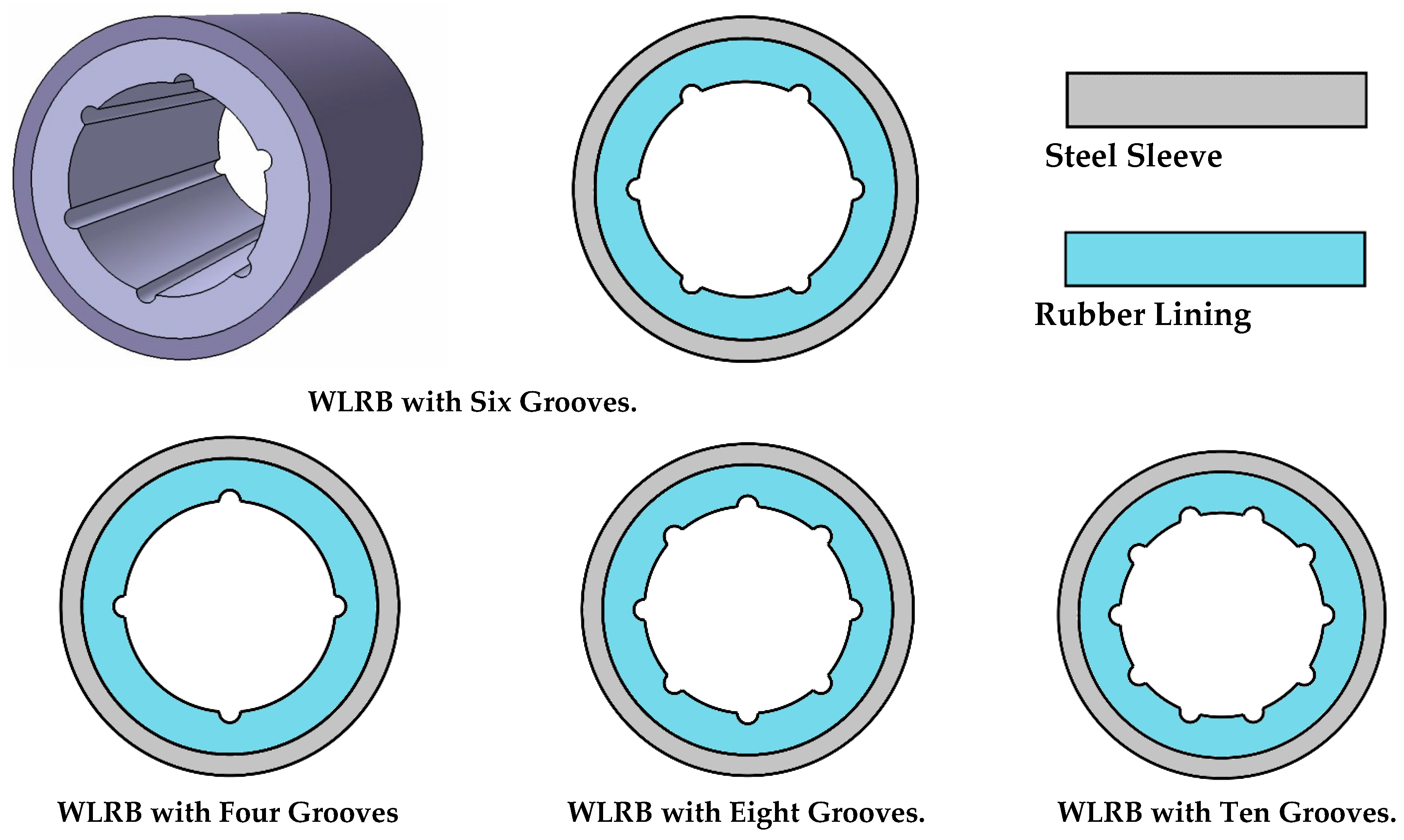
Figure 1 illustrates the grooved rubber journal bearing configurations with 4, 6, 8, and 10 grooves investigated in this study.
The growing use of rubber journal bearings has motivated numerous studies focused on examining and enhancing their performance behavior. Using finite element modeling, Majumdar et al. assessed the stability of rubber bearings featuring grooves [
2]. Their findings indicated that reducing the groove angle enhances load-bearing capability because of elevated pressure levels. He and his co-authors constructed an integrated lubrication framework that accounts for cavitation effects [
3]. Through this model, they effectively measured considerable deflection of the shaft within the region of maximum pressure. Gengyuan et al. introduced a new bearing liner featuring a transition-arc geometry aimed at increasing the hydrodynamic load capacity in water-lubricated journal bearings [
4]. They performed three-dimensional computational fluid dynamics simulations to examine how variations in transition-arc size affect load capacity, while keeping the radial gap, eccentricity ratio, and rotational speed of the shaft unchanged. Their results revealed a clear relationship between the transition-arc geometry and load-carrying performance across different L/D ratios, providing practical design guidelines for engineers. Liu and Yang developed a mathematical representation of WLRBs [
5]. Their findings revealed that an increased eccentricity ratio enhances dynamic coefficients; however, this improvement comes at the cost of higher energy dissipation.
Through laboratory experiments, Cabrera et al. found that the manner in which fluid pressure distributes itself within rubber bearings deviates from typical patterns [
6]. This highlights why elastic deflection of the rubber liner must be considered when evaluating bearing performance. De Kraker carried out real-world testing to generate Stribeck curves and clarified how various design parameters affect both the friction coefficient and the smallest thickness of the lubricant film [
7]. Experimental work conducted by Geng et al. showed that, compared to inlet water pressure, both applied load and rotational speed have a stronger influence on how pressure is distributed and on the peak pressure value [
8]. Wang and co-authors developed an innovative rubber bearing liner incorporating two cavities, with the goal of achieving sustained hydrodynamic lubrication in water-lubricated bearings [
9]. Their results revealed that there is an ideal clearance value that both reduces the friction coefficient to its lowest point and raises load capacity to its highest level. Ouyang et al. modeled shaft misalignment by means of unbalanced rotor movement and observed that establishing a stable lubricant film becomes difficult when rotational speeds fall under 700 rpm [
10]. In a later study, Ouyang et al. addressed the limitation of the straight shaft assumption in marine water-lubricated bearings by proposing a fluid–solid coupling model that incorporates journal bending [
11]. Their results demonstrated that shaft bending causes water film pressure to peak at both bearing ends and leads to asymmetrical distribution of lubrication performance; increasing eccentricity and decreasing lining Young’s modulus aggravate this aggregation while increasing load capacity.
The study by Rashidi Meybodi et al. on the effect of non-Newtonian fluid behavior on lobed journal bearing performance demonstrated that employing micropolar lubricants can effectively optimize the dynamic characteristics and improve the efficiency of these bearings [
12]. Smith developed a 3D EHL framework that correlates the normalized film thickness to the clearance ratio and load conditions [
13]. According to this model, film thickness grows as clearance and load decrease. The study also offered approximate formulas for different numbers of grooves. A comprehensive investigation into the behavior of non-Newtonian lubricants, such as micro-polar, power-law, and couple-stress lubricants, in journal bearings has been conducted by Dang et al. The findings suggest that under specific operational conditions, these lubricants can significantly enhance the efficiency and reliability of bearings compared to Newtonian lubricants [
14]. Harika et al. investigated the instantaneous effects of water contamination in lubricating oils on hydrodynamic lubrication for water concentrations up to 10% by mass. Through rheological and thermal modeling of the water–oil mixture, combined with experiments on a tilting pad thrust bearing, they identified conditions under which water presence is detrimental as well as potentially beneficial. Interestingly, their findings revealed that pure oil could be replaced by a water-in-oil emulsion with the same viscosity, leading to weakly modified film thickness and friction coefficient but significantly lower operating temperatures—a notable safety advantage [
15].
Zhou et al. carried out a study centered on minimizing noise and vibration levels [
16]. They found that elevated friction and pressure tend to intensify both vibration and noise, while enhancing the stiffness of supports has the opposite effect of diminishing them. Feng et al. studied how partial slip at the wall surface influences hydrodynamic lubrication [
17]. Their results showed that herringbone-grooved bearings provide the greatest load capacity, with helical-grooved and straight-grooved bearings ranking next in order. Du and Quan put forward mixed-flow lubrication formulations [
18]. According to their work, raising the eccentricity ratio causes the lubricant film to become thinner, whereas higher rotational speed leads to greater pressure generation. Through experimental work, Litwin and his team examined wear in the presence of contaminated water [
19]. They observed that the choice of bearing material and various design factors—such as elevated water flow rates and rapid shaft rotation at startup—play a role in determining the extent of wear. A fluid–solid coupling model was developed by Zhang, through which an ideal groove-to-width area ratio of 0.31 was identified for rectangular micro-grooves [
20]. This optimal value enables enhanced load capacity while simultaneously reducing frictional resistance.
According to Zhang and his team, when speeds are low and friction coefficients remain under 0.1, stick-slip vibration ceases to occur [
21]. However, this type of vibration continues to appear during the startup phase, regardless of how small the friction may be. Liu et al. carried out experiments on bearings equipped with various bushing materials [
22]. Their results showed that under demanding operating conditions, the modified polyurethane bushing outperforms others. This finding also draws attention to an important specific pressure characteristic associated with grooved bearings. Yang et al. found that rotating spiral micro-grooves provide the most favorable tribo-dynamic behavior [
23]. The ideal groove angles, however, vary according to load magnitude, groove depth, and groove width. By employing computational fluid dynamics together with Taguchi methods, Ganesha et al. determined the best parameter set for a bearing with four grooves [
24]. Their optimization ultimately indicated that two grooves represent the ideal number. Gu et al. introduced a multi-objective optimization tool based on the Grey Wolf algorithm, designed specifically for surface texturing in journal bearings [
25]. This approach enhanced the uniformity of oil film thickness and minimized irregular contact between surfaces. Li and his team computed both stiffness and damping coefficients [
26]. Their calculations revealed that the radial gap, along with the ratio of bearing length to diameter, exerts a strong influence on dynamic behavior. Wang et al. proposed a viscoelastic hydrodynamic lubrication framework tailored to water-lubricated rubber bearings (WLRBs) [
27]. This model offers improved characterization of rough surface topographies and delivers precise assessments of lubrication behavior by accounting for non-linear elastic deformation.
The rheological behavior of seawater, characterized by the presence of suspended solids, mineral salts, biopolymers, and microorganisms, exhibits a complexity that deviates from that of a purely Newtonian fluid [
28,
29]. Although seawater generally behaves close to Newtonian, minor viscosity variations caused by the interaction of particles and polymers can significantly alter the operational properties of seawater-lubricated bearings [
30,
31]. Seawater exhibits non-Newtonian characteristics due to the presence of very fine suspended solids such as clay, silt, dissolved organic matter (DOM), biopolymers, and exopolymers [
32,
33]. Neglecting this rheological characteristic (e.g., shear thinning) can lead to errors in the prediction of pressure distribution and bearing load-carrying capacity [
34,
35].
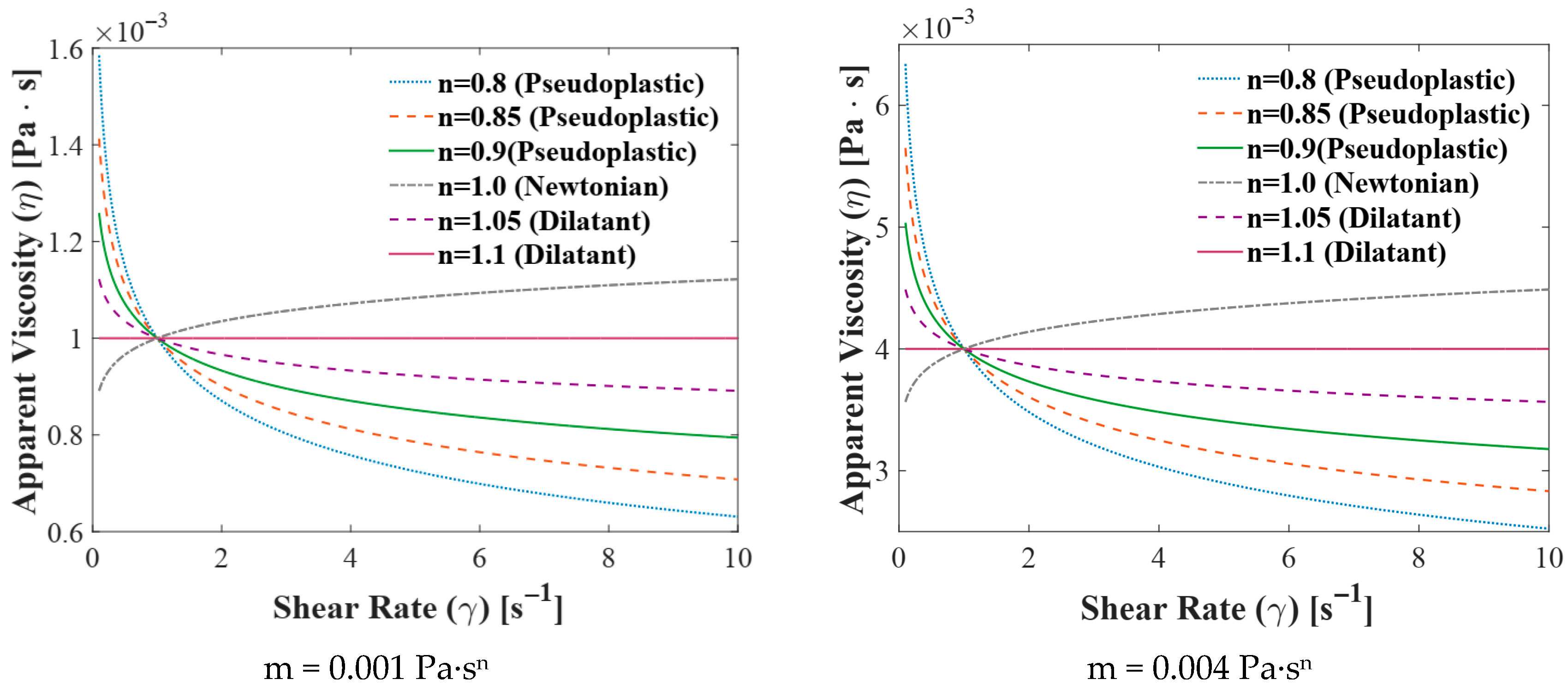
To facilitate a more precise analysis of the rheological behavior of seawater,
Figure 2 presents the apparent viscosity (η) as a function of shear rate (
) for two consistency index (
m) values, specifically m = 0.001 Pa·s
n and m = 0.004 Pa·s
n, utilizing the power-law model. These plots, which encompass a wide range of the flow behavior index (
n) within the scope of this study, effectively illustrate the non-Newtonian nature of seawater due to the presence of various dissolved and suspended constituents (such as suspended solids and salts).
This research is presented with the aim of achieving more accurate modeling of rubber bearing performance in seawater environments, as the real operational environment necessitates the consideration of more complex fluid and structural effects. Accordingly, the modeling is conducted by incorporating the non-Newtonian behavior of seawater instead of the simple Newtonian approximations prevalent in most prior studies. Herein, the power-law approach is utilized to capture this behavior. The consistency index (m) is determined to be within the range of 0.001 to 0.004 Pa·sn, and the power-law index (n) falls between 0.8 and 1.1. The selected range for n, with a focus on values below unity (shear-thinning/pseudo plastic), is based on the observation that most natural fluids containing organic matter exhibit pseudo plastic behavior. Prioritizing this range enhances the generalizability and reliability of the results across diverse operational conditions. This chosen range not only covers empirical evidence but also establishes a precise balance between the deviation from Newtonian behavior and the operational requirements for maintaining bearing stability and load-carrying capacity. Furthermore, the elastic deformation of the rubber bush, a critical factor in system stability, is accounted for by employing the Winkler elastic model, a consideration seldom addressed in seawater lubrication studies. Given that the rheological properties of seawater can vary across different locations, examining bearing performance across various configurations (4 to 10 grooves) allows for the identification and selection of the optimal design best suited for the variable properties of seawater, significantly enhancing the applicability of the results.
2. Research Model
The pressure profile within grooved rubber journal bearings (GRJBs) is inherently distinct from that observed in conventional circular hydrodynamic bearings, owing to two contributing factors: the existence of grooves and the elastic deflection of the bushing. Consequently, any derivation of the pressure distribution must take into account both of these effects together. Water, serving as the lubricant, possesses low viscosity, which forces these bearings to function within the thin-film lubrication regime. Under such conditions, the grooves become essential for delivering and directing the lubricant toward the region that carries the load.
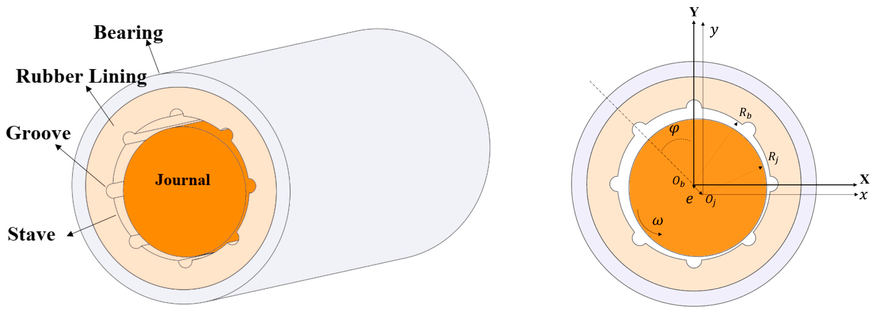
Figure 3 illustrates the schematic of the grooved bearing components and their geometric parameters. In this figure,
is defined as the center of the journal, and
is the center of the bearing.
The present study relies on conventional assumptions drawn from fluid dynamics and solid mechanics to model the bearing’s behavior. These assumptions are outlined below:
The journal is treated as a rigid component.
The fluid motion is assumed to be laminar, with the lubricant exhibiting incompressible behavior [
36].
Any pressure change occurring across the thickness of the lubricant film is neglected.
Body forces, including gravitational effects, are regarded as insignificant when compared to the pressure forces generated by hydrodynamic action.
2.1. Governing Equations
The Reynolds equation serves to characterize the hydrodynamic performance of the bearing. This equation is a partial differential equation that models the pressure distribution in the film between two moving or stationary surfaces. This equation is derived from the simplification of the Cauchy momentum equations and the continuity equation (Equations (1a) and (1b)).
In this equation,
is the density,
is the velocity vector,
is the Cauchy stress tensor,
is the body force vector. By applying the assumptions related to the bearing operating conditions and the flow characteristics in the thin layer of lubricating fluid, the Cauchy and continuity equations are simplified, and ultimately Equations ((2a)–(2c)) and (3) are obtained to describe the flow in the x and z directions.
For a “power-law” fluid, the shear stress components are defined in terms of the shear rate as follows [
37]:
In these relations,
is the apparent viscosity, which is defined by Equation (5).
In these relations,
n is the power-law index and m is the consistency index. The pressure variation equations for the power-law model will be as described by Equations (6a) and (6b).
By integrating the simplified momentum conservation equations for the power-law fluid and substituting them into the continuity equation, the generalized Reynolds equation for the power-law fluid is derived, which is presented as Equation (7) [
36].
In this equation, h is the lubricant film thickness, which in this study is the sum of the standard bearing film thickness, the groove effect on the lubricant layer thickness, and the effect of rubber bush deformation, and will be calculated using Equation (8) [
38].
Within this equation,
accounts for the influence of the groove on film thickness, while
represents the contributions from the elastic deformation of the rubber bush. For the purposes of this study, the angular positions (in degrees) marking where each groove begins and ends are specified in
Table 1. This applies to bearings containing 4, 6, 8, or 10 grooves. For a better comparison of the effects of the number of grooves, the dimensions of the grooves were reduced proportionally as the number of grooves was increased, so that the final area of the grooves and carriers remained constant across all configurations.
To simulate elastic deformation of the bush, the Winkler elastic model is employed. Under this model, the rubber bush is represented by an array of uncoupled springs, meaning that shear forces between adjacent springs are neglected. Reference [
39] defines the effective elastic modulus
via Equation (9). For any point along the coating, the elastic deformation—dependent on the applied pressure (
P) and the bush thickness (l)—is calculated using Equation (10) [
40]. Here,
stands for Poisson’s ratio.
2.2. Method for Solving the Equations
The numerical solution framework for this analysis is based on discretizing the domain using the finite element method (FEM). The dimensionless form of the Reynolds equation is presented in Equation (11).
After discretizing the domain and deriving the weak form of the Reynolds equation, the pressure equation corresponding to each finite element is given by Equation (12). Additionally, Equations (13a)–(13c) presents the coefficient matrices associated with the terms of this equation for every element. It should be noted that rectangular isoparametric elements are utilized in this study.
The dimensionless form of the boundary conditions is shown in Equations (14a) and (14b).
Another condition investigated is the phenomenon of cavitation, which is examined in the Staves (the space between two grooves). It is worth noting that investigating the cavitation conditions (Equation (15)) in the grooves, which do not have a load-bearing function and are mostly pressure-free regions, is unnecessary. In these regions, since there is no pressure distribution (due to the high lubricant film thickness), the pressure remains constant and tends to zero, and the cavitation conditions are inherently satisfied. However, this does not confirm the occurrence of cavitation; therefore, the cavitation criterion must only be examined in the load-bearing regions.
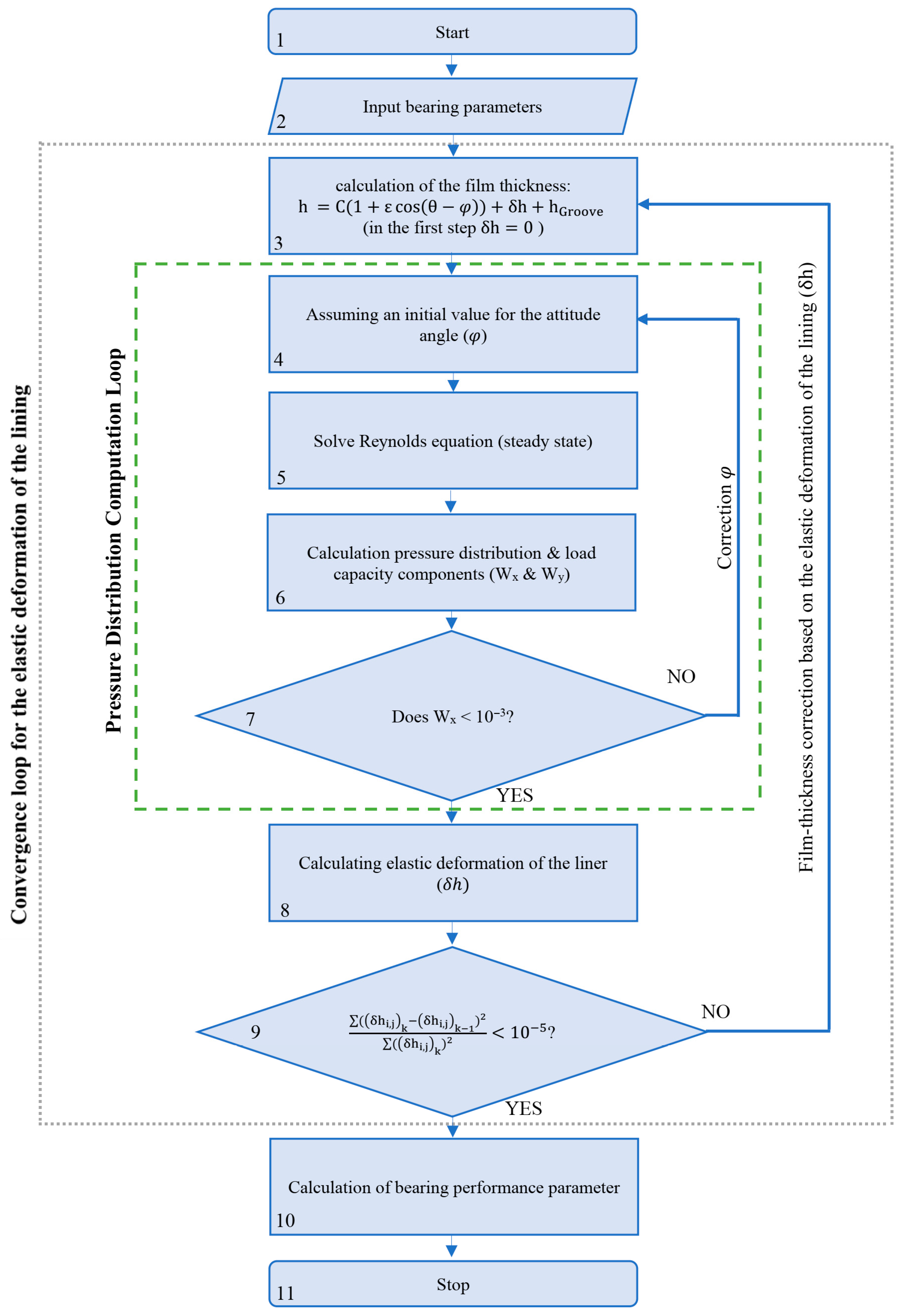
The process starts with the input of initial parameters, namely the bearing’s geometric characteristics: radius, aspect ratio (), eccentricity ratio (), lubricant viscosity (), and the initial attitude angle (). Next, the initial thickness of the lubricant film is computed using Equation (8). Afterward, the Reynolds equation is solved in order to obtain the pressure distribution. Importantly, during the first iteration of this solution process, elastic deformation of the liner is disregarded (i.e.,).
To confirm the accuracy of the calculated pressure profile, the equilibrium condition requiring a zero horizontal load component () is verified. Should this requirement not be fulfilled, the attitude angle () is modified, and the computational routine is reinitiated. This iterative loop proceeds until the pressure distribution complies with the stated condition.
Following the determination of an admissible pressure field, the elastic deflection of the liner is obtained from Equations (9) and (10). The resulting deflection is subsequently introduced into Equation (8) to yield a revised lubricant film thickness. Using this updated thickness, the iterative cycle resumes the search for a pressure distribution that fulfills the criterion.
This process, which involves computing the pressure field and subsequently adjusting the lubricant film thickness based on the results, is carried out through iterative steps. At each iterative stage, the newly derived valid pressure distribution prompts a recalculation of the elastic deformation of the liner. This, in turn, leads to a further refinement of the lubricant film thickness, as defined in Equation (8). Concurrently, with every update of the lubricant film thickness, the valid pressure distribution is re-examined to confirm that it still satisfies the condition.
The iteration proceeds until the error function for the liner’s elastic deformation () between consecutive steps drops below 10−5. Meeting this convergence criterion indicates that a stable solution has been attained, allowing the pressure distribution to be accurately calculated while incorporating the effects of the liner’s elastic deformation.
The procedure for solving the problem using the proposed model is illustrated in
Figure 4. Once the results have converged to a stable state, the primary static performance parameters—namely, load carrying capacity, peak pressure, friction coefficient, and dimensionless friction force—are computed according to the following relationships.
2.3. Mesh Study
To ensure the stability of the numerical solution and to eliminate any dependency of the results on the spatial discretization, a comprehensive mesh independence study was conducted using the finite element method. To model the fluid motion within the grooved rubber journal bearing (GRJB), the geometry was discretized using elements capable of accurately capturing pressure variations, especially near internal features.
The mesh refinement process was performed by progressively increasing the number of elements within each stave. After each refinement step, the pressure field was compared with that obtained in the previous step. The convergence criterion was defined as a relative pressure error of less than 0.001 between two successive meshes, indicating that further refinement no longer produced a meaningful change in the numerical solution.
This procedure was independently carried out for all configurations under study, namely bearings with 4, 6, 8, and 10 grooves, to account for geometric sensitivity to mesh density.
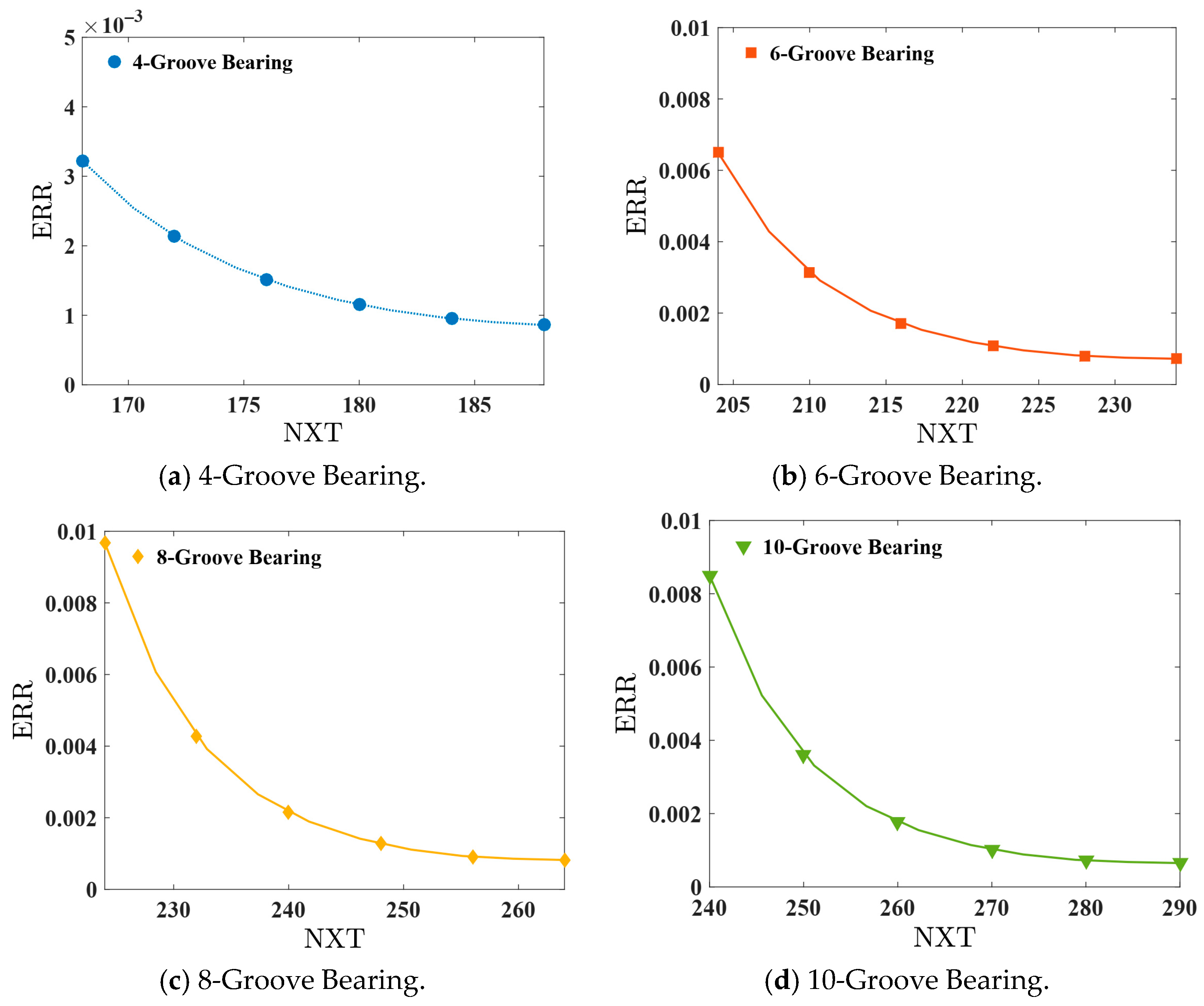
Table 2 presents the final mesh dimensions that meet the convergence criterion for each configuration. These findings verify that the chosen meshes offer adequate resolution and that the static performance results of the bearing are essentially independent of the mesh.
The mesh parameters are defined in
Table 2 as follows: NXS is the element count in the stave along the x-direction; NXG represents the element count within the groove along the x-direction; NXST denotes the total number of x-directional elements in the stave, given by NOG multiplied by NXS; and NXT indicates the overall x-directional element count, computed as NOG times the sum of NXS and NXT.
The mesh models presented in
Table 2 exclusively utilized 4-node bilinear isoparametric quadrilateral elements. Within this element formulation, the pressure field is computed at the element’s nodal vertices. To achieve higher accuracy in evaluating geometric properties, such as lubricant film thickness and groove geometry, which can vary significantly along the element’s length, additional sampling points were incorporated. These sampling points facilitate a more precise capture of these variations within each element without increasing the nodal count. The mesh strategy, including the type of element and the use of these sampling points, remained consistent across all bearing configurations (4, 6, 8, and 10 grooves) and mesh refinement levels. The sole difference among the mesh models listed in
Table 2 pertains to the total number of elements employed to ensure mesh independence.
Figure 5 displays the mesh convergence curves for bearings with 4, 6, 8, and 10 grooves. These plots assess the numerical solution’s convergence status as the mesh element count increases, indicating that different configurations approach stable values with finer meshing.
2.4. Model Validation
A stringent validation procedure was carried out to verify the precision and dependability of the numerical model established in this investigation. If the bearing is selected with a single groove and the groove dimensions are chosen to be infinitesimally small, the grooved bearing configuration transforms into a simple circular bearing. This allows for the validation of the proposed model against Refs. [
41,
42], which includes approximate results for a plain circular bearing.
Table 3 and
Table 4 illustrate the dimensionless maximum pressure output from this investigation, compared with the reference, along with the percentage difference.
3. Results and Discussion
The outcomes derived from solving the governing equations using the proposed model reveal that the pressure within the groove regions approaches zero. This phenomenon occurs due to the significant thickness of the lubricant layer in these areas. In contrast, in the load-carrying zones (the regions between two grooves), which fall within the range of positive pressure, distinct pressure peaks are observed. The number of these pressure peaks is directly proportional to the number of grooves on the bearing. In other words, as the number of grooves increases, the number of pressure peaks also rises. For example, in a four-groove bearing, at least two peaks are observed; in a six-groove bearing, at least three peaks; in an eight-groove bearing, at least four peaks; and in a ten-groove bearing, at least five pressure peaks.
However, it is important to note that with an increase in the number of grooves, the magnitude of each pressure peak (i.e., the maximum pressure) decreases. This reduction means that the lubricant becomes less capable of reaching high pressure levels. Consequently, despite the increase in the number of pressure peaks, the overall load-carrying capacity of the bearing diminishes as the number of grooves increases, since the achievable pressure becomes lower. The initial parameters used for bearing analysis are presented in
Table 5.
The groove dimensions were designed such that the total area of the bearing surface and the grooves remained constant across the configurations under investigation. Accordingly, for this research, the groove dimension ratio (d/D) was set to 0.15, 0.10, 0.075, and 0.06 for bearings with 4, 6, 8, and 10 grooves, respectively. This parameter control enables the analysis of the effects of changing the number of grooves independently.
Table 5.
Input parameters for the research model.
Table 5.
Input parameters for the research model.
| Parameter | Value (Unit) |
|---|
| Eccentricity ratio () | 0.7 |
| Aspect ratio (L/D) | 1 |
| Groove dimension ratio (d/D) | 0.15, 0.10, 0.075, 0.06 |
| Clearance ratio (C/R) | 0.001 |
| Poisson’s ratio (ν) | 0.45 |
| Shaft speed | 200 m/s |
| Radius | 0.2 m |
| Power-law index (n) | 0.8–1.1 |
| Consistency index | 0.002 Pa·sn |
3.1. Power-Law Index (n)
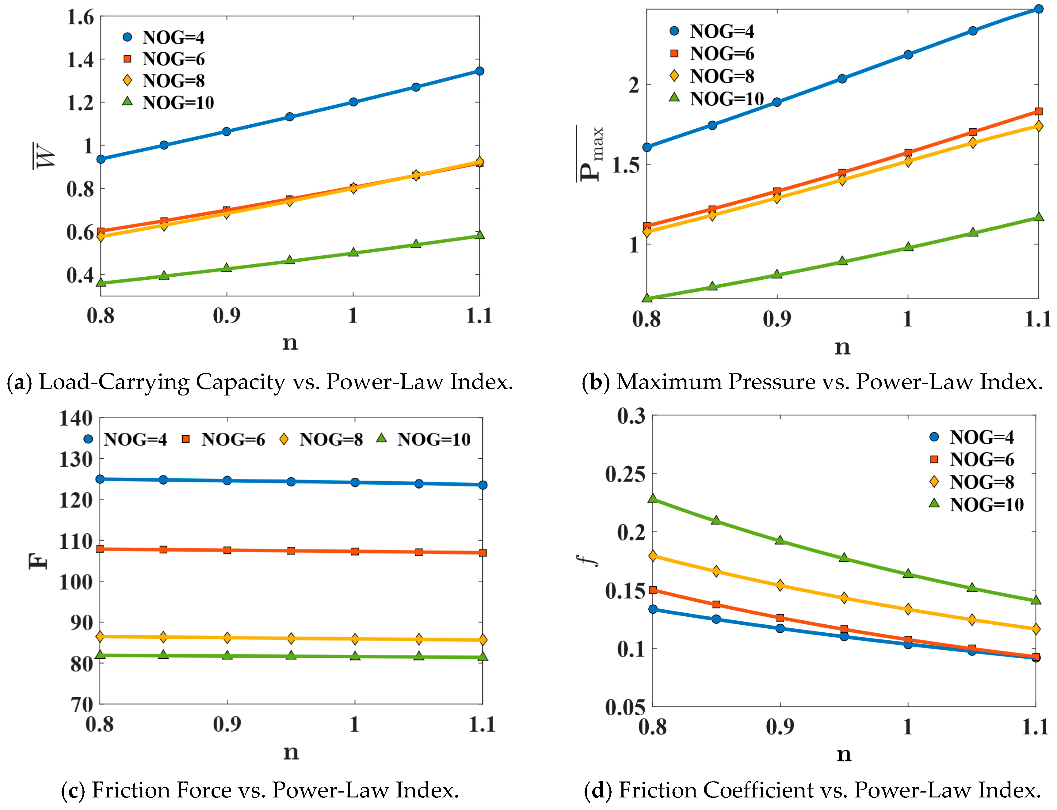
Figure 6 presents the changes in maximum pressure (
), load-carrying capacity (
), friction coefficient (
), and dimensionless friction force (
F) as functions of the power-law index, which is used as the independent parameter over a range of 0.8 to 1.1. The results are shown for bearings with 4, 6, 8, and 10 grooves. In the extraction of these figures, the consistency index was held constant at 0.002 Pa·s
n.
The findings from the analysis of a bearing lubricated with a power-law non-Newtonian fluid reveal that variations in the power-law index () exert a direct and substantial influence on the bearing’s hydrodynamic behavior. Increasing , which corresponds to a rise in the fluid’s apparent viscosity under high shear rates, promotes the development of the hydrodynamic wedge within the film’s convergent zone. This alteration results in an elevation of the peak pressure () and, subsequently, an enhancement of the bearing’s load-carrying capacity. This outcome aligns well with the expectations of power-law rheological theory and with existing experimental evidence in the literature, since a fluid possessing a higher effective viscosity offers greater resistance to shear flow, thereby amplifying the pressure distribution.
The enhancement of pressure and the increase in effective viscosity also contribute to greater stability of the lubricant film. This reality leads to the lubricant film becoming not only thicker but also more stable, which significantly impacts the surface’s frictional behavior. The observed decrease in the dimensionless friction coefficient can be attributed to a reduction in relative shear stress at the walls. In other words, although higher viscosity tends to increase shear stress, the thickening of the film and the improved formation of the hydrodynamic wedge lead to a decrease in effective shear rate and, consequently, a reduction in the friction coefficient. This behavior has been reported in many numerical analyses related to pseudoplastic fluids in the range of .
Conversely, the constant dimensionless friction force F within this parametric range indicates that the ratio of shear stress to effective pressure remains approximately constant. This signifies that the friction generation mechanism in the bearing is primarily controlled by the hydrodynamic regime, and changes in n solely alter the pressure distribution and film thickness, not the ratio of effective stresses. However, since the load-carrying capacity grows with increasing n, the dimensional (actual) friction force also naturally increases, as it is equal to the product of the constant F and a larger load.
In summary, raising the power-law index improves the hydrodynamic performance of the bearing: pressure intensifies, load-carrying capacity rises, film stability is enhanced, and the friction coefficient diminishes. Although the dimensional frictional energy slightly increases, this rise is a direct consequence of increased load capacity rather than a deficiency in the lubricant’s performance. Therefore, utilizing power-law fluids with
n > 1.0 can be an effective option in bearing design to achieve higher load capacity and reduce the friction coefficient in medium to heavy load applications.
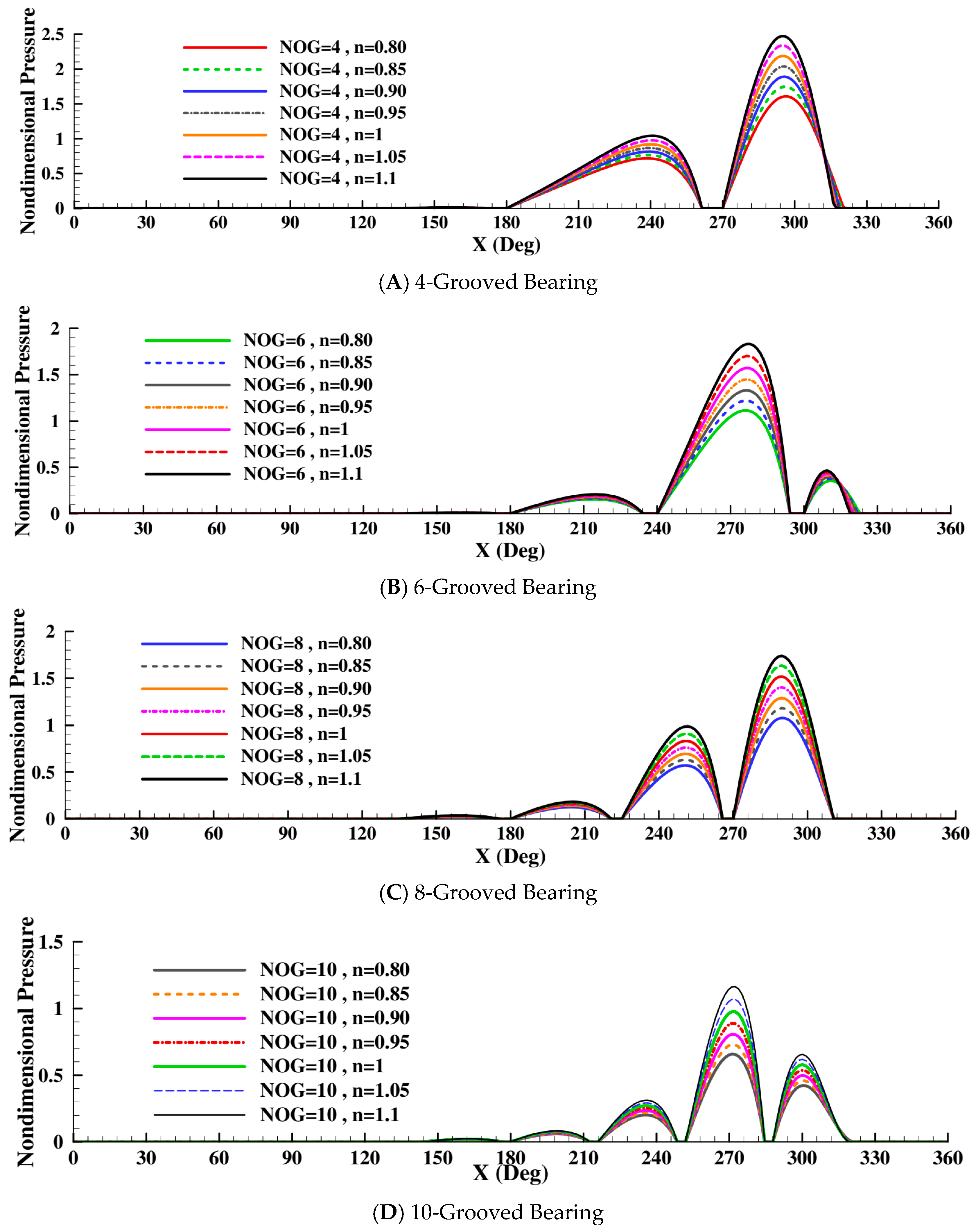
Figure 7 also illustrates the pressure distribution along the centerline of the WLRB with 4, 6, 8, and 10 grooves and a power-law index ranging from 0.8 to 1.1. In these plots, the consistency index is 0.002 Pa·s
n.
It is evident from the examination of the graphs that increasing the fluid power-law index has no effect on the pressure distribution within the bearing grooves, where the pressure remains zero.
Taking a holistic view, an increase in the number of grooves, which is equivalent to increasing the number of pressure peaks on the load-bearing surface, reveals two significant effects:
First, as the number of grooves increases, the hydrodynamic maximum pressure decreases. The reason for this drop is that at the points where the pressure drops to zero (the location of the grooves), the fluid does not have sufficient opportunity to fully develop its pressure profile and reach its maximum value. Consequently, the pressure-forming regions become segmented, and before the pressure can fully develop, a sharp drop occurs again at the next groove location down to zero.
Second, the increase in the number of pressure peaks leads to greater fluctuations in the surface pressure gradient. This phenomenon results in a rise in the effective friction coefficient because rapid fluctuations in pressure and lubricant film thickness contribute to higher energy dissipation. Although the dimensionless friction force may show limited variation under certain loading conditions, the overall power dissipated by the system shows an increasing trend with a higher number of grooves. Equations (18a) and (18b) also indicates that an increase in the pressure gradient in the amplitude will result in an increase in the friction force.
Despite these negative effects, increasing the number of grooves can improve lubricant flow and enhance the heat exchange surface area. Therefore, the designer is compelled to strike a balanced approach among the bearing’s load capacity, friction, and cooling efficiency.
Analysis of Capacity and Pressure: The results demonstrated that as the fluid power-law index increases, both the maximum pressure and the bearing load capacity increase non-linearly and exponentially. This behavior indicates that by improving the rheological characteristics of the fluid (increasing the power-law index in the power-law model), the hydrodynamic forces within the lubricant layer are strengthened, allowing for the formation of a denser and more resilient film. In essence, the higher the power-law index, the more stable the fluid flow remains in regions of high shear gradient, resulting in a more effective pressure generation.
Friction Analysis: The effect of the power-law index on the dimensionless friction force is nearly neutral, showing no significant changes. However, given that the load-carrying capacity increases along with this index, the effective friction coefficient declines in accordance with Equation (19). This implies that increasing the non-Newtonian behavior of the fluid (high power-law index type) can improve the bearing’s frictional performance. In this scenario, less energy is consumed to overcome the shear resistance, and the system operates more efficiently from a mechanical efficiency standpoint.
Sensitivity Analysis to the Power-Law Index: The sensitivity study of the parameters to changes in the power-law index reveals that the peak maximum pressure is more sensitive than the load capacity. In other words, the initial impact of changing the power-law index appears in the pressure along the bearing centerline and then gradually affects the overall load-bearing behavior of the system. Furthermore, the intensity of the effect is greater at the center of the bearing than in the peripheral regions, indicating a concentration of hydrodynamic stresses in this section. Comparative plot results for bearings with 4, 6, 8, and 10 grooves with power-law indices ranging from 0.8 to 1.1 confirm that increasing the number of grooves increases the sensitivity of the pressure distribution to the power-law index at lower pressures.
In conclusion, the findings suggest that variations in the power-law index and the geometry of the load-bearing surface are two key factors in determining the pressure pattern and energy losses within the bearing. In a well-considered design, controlled increases in the number of grooves can be leveraged for better cooling, and the selection of a fluid with a suitable power-law index can achieve higher load capacity with reduced friction. This comparative perspective demonstrates that novel design solutions must be formulated by considering the interaction among geometry, lubricant rheology, and loading conditions to maximize the overall system efficiency.
3.2. Consistency Index (m)
Some lubricants, such as seawater, can exhibit different physical and rheological properties across various regions and under different environmental conditions. Considering seawater as a fluid containing salts and suspended particles, its behavior is analogous to a shear-thinning fluid (pseudoplastic). Under these conditions, the consistency index (m) is reported to be in the range of 0.001 to 0.004 Pa·s
n [
29].
Given the reported range for the consistency index, this interval has been adopted as the primary parametric range for the consistency index in the analyses conducted in this research. To examine the effect of these parameters,
Table 6 presents the static characteristics of the grooved rubber bearing under the condition of
n = 1 and for the four studied configurations. This table presents essential performance indicators, including the dimensionless maximum pressure (
), the actual maximum working pressure (in kPa), the dimensionless load-carrying capacity along with its actual value (in kN), the friction coefficient (
), and the dimensionless friction force (
F).
Moreover,
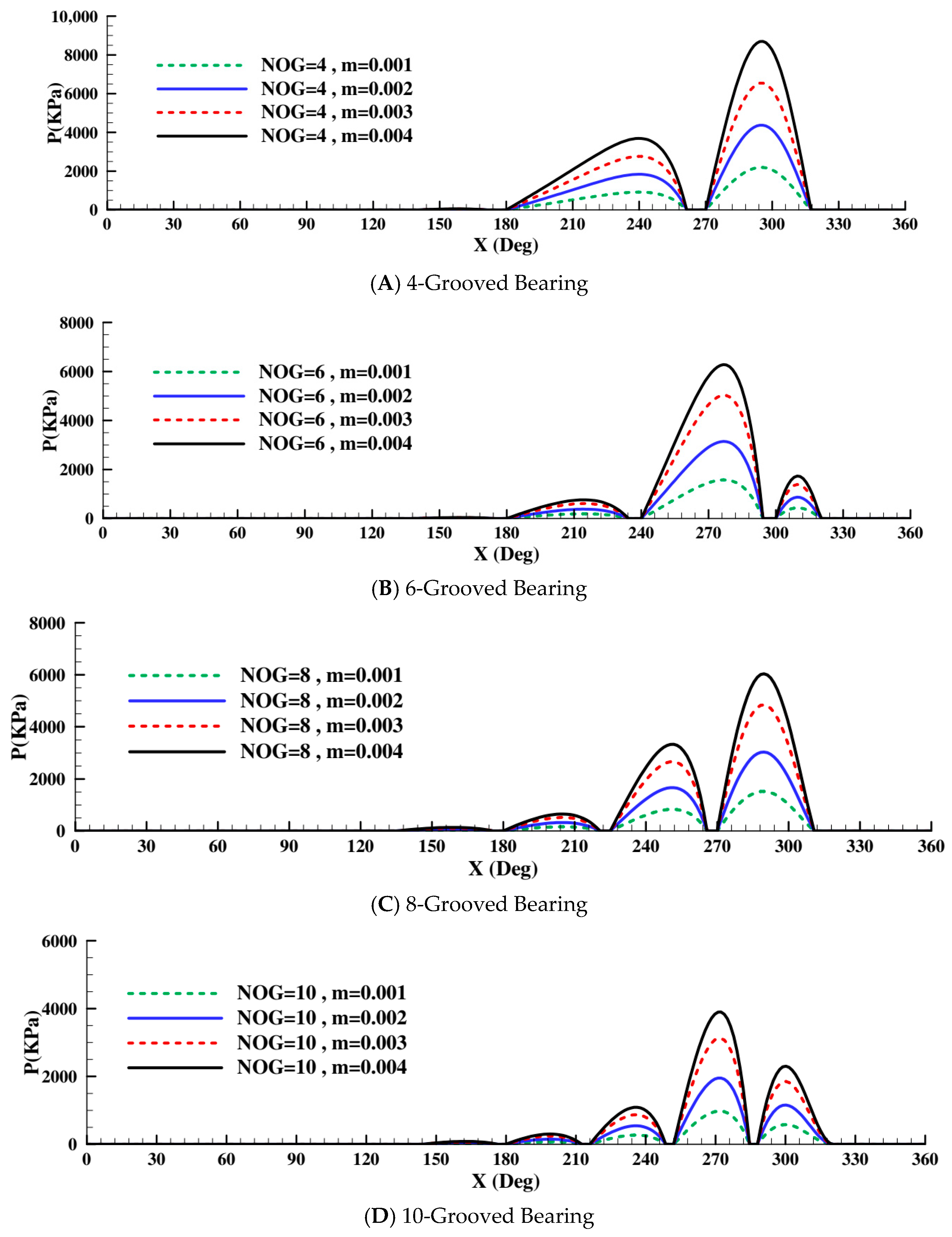
Figure 8 individually demonstrates the influence of these conditions on the pressure distribution along the bearing centerline for the case where
n = 1, across the four configurations examined.
Examination of the pressure profile along the bearing centerline for all four studied configurations (presented in
Figure 7) reveals that an increase in the consistency index leads to a higher maximum pressure in this region. This observation aligns with the corresponding rise in the fluid’s apparent viscosity. In contrast, variations in the consistency index do not influence the pressure distribution within the groove regions; owing to the discontinuity of the lubricant film, the hydrodynamic pressure in those zones remains at zero.
As demonstrated in
Table 6, over the range of parameters examined, the dimensionless values of the key performance indicators—specifically the dimensionless pressure distribution, dimensionless load-carrying capacity, dimensionless friction force, and friction coefficient—show little variation with changes in the consistency index. This stability confirms the dimensionless nature of these parameters, as the dimensionless form of the Reynolds equation (Equation (11)) is inherently independent of this index. Nevertheless, a rise in the fluid’s consistency index is directly linked to higher actual values of both the bearing’s load-carrying capacity (kN) and its maximum operating pressure. This behavior results from the enhanced resistance of the fluid to shear stress as its concentration—or consistency—increases.
A crucial point is the interplay between the working pressure and the elastic deformation of the rubber bush. The increase in working pressure in the bearing causes the elastic deformation of the bush. This deformation, in turn, affects the lubricant film thickness (according to Equation (8)), and the increase in lubricant thickness in high-pressure regions leads to a reduction in the local maximum pressure. In Equation (8), the variable represents the contribution of the rubber bush’s elastic deformation to the lubricant film thickness at any location within the domain. In other words, in bearing analysis, there are two approaches: first, if the bearing bush is considered rigid, a change in the consistency index will have no effect on the dimensionless values, and these values remain constant. Second, if the elastic deformation of the bush is included in the calculations, these dimensionless values change due to the effect of deformation on the lubricant film thickness. The magnitude of these changes will be proportional to the extent of the elastic deformation of the bush under operating conditions.
Given that the elastic deformation of the rubber bush is inversely proportional to the elastic modulus of the rubber (
E) and directly proportional to the bush thickness (l), a comprehensive parameter called the “Effective Bush Stiffness” is defined as the ratio of the elastic modulus to the bush thickness (
). This parameter represents the combined effect of changes in the elastic modulus and the thickness of the rubber on the elastic deformation of the rubber bush.
Table 7 shows the variations in maximum working pressure (kPa) and the maximum dimensionless pressure of the rubber bearing with 6 grooves, as a function of changes in the effective stiffness of the rubber bush. The input values are the same as those in
Table 5, with the power index
n = 1.
Based on the results presented above, it can be understood that employing a non-Newtonian fluid model can provide a basis for more accurate analysis and achieve results closer to reality for hydrodynamic grooved rubber journal bearings (GRJBs) lubricated with fluids that exhibit behavior different from Newtonian fluids due to the presence of additives, particles worn from surfaces, impurities, contaminants, or specific chemical compositions. The power-law model is a comprehensive model in which variations in its characteristic parameters can cover a significant behavioral range of non-Newtonian fluids.
According to the conducted analysis, achieving a favorable overall performance results from the proper adjustment of the lubricant fluid characteristics, the geometric features of the grooved journal bearings, and the material of the components that constitute this type of bearing support.
3.3. Eccentricity Ratio (ε)
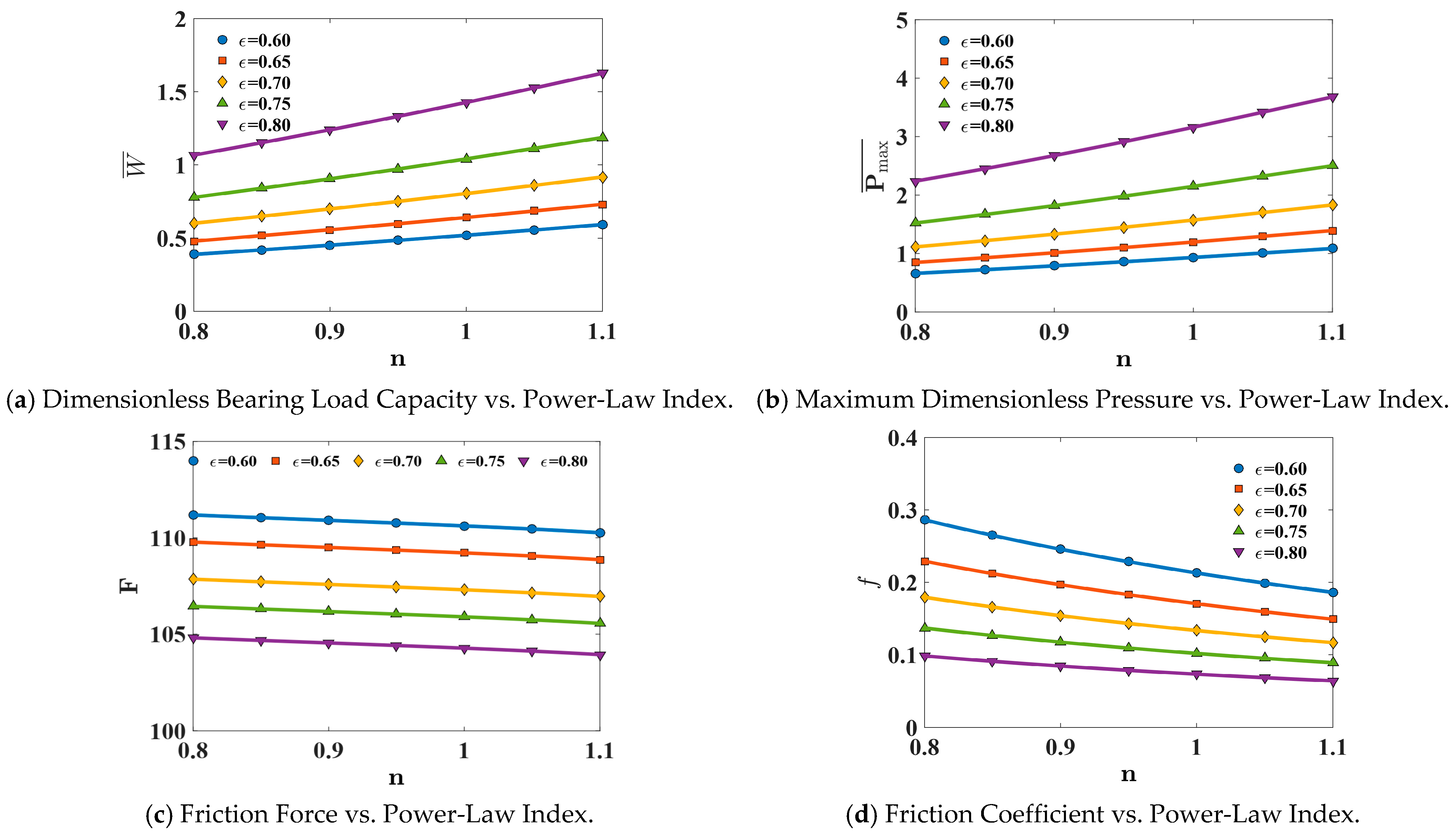
The effect of the eccentricity ratio (ε) on fundamental bearing performance parameters—specifically load-carrying capacity, maximum pressure, friction coefficient, and friction force—is examined in this section. Numerical data for eccentricity ratios in the range of 0.6 to 0.8, and for different values of the Power-law index (
n) and grooved bearings, have been analyzed. The corresponding plots are shown in
Figure 9.
The results from the numerical data analysis unequivocally indicate that as the eccentricity ratio (ε) increases, the bearing’s load-carrying parameters significantly improve. With an increase in ε from 0.6 to 0.8, a direct increasing trend in load-carrying capacity is observed. This implies that under higher eccentricity conditions, the bearing can withstand greater loads.
Concurrently with the increase in load-carrying capacity, the maximum pressure generated within the lubricant film also rises with increasing ε. This pressure increase is the primary factor enabling higher load support and signifies the formation of a stronger and more stable lubricant film under greater eccentricity.
One of the most significant and intriguing findings of this research is the continuous decrease in friction despite the increase in load. The friction coefficient shows a decreasing trend as ε increases. This reduction indicates a substantial improvement in lubrication quality and a decrease in energy losses due to surface slip. The friction force also decreases with increasing ε. This reduction is a result of the synergy between the decreased friction coefficient and the optimization of the lubricant film’s geometry under higher eccentricity conditions.
From the plots, it is evident that the friction coefficient is inversely related to the dimensionless load parameter. This means that as the load the bearing can carry increases (due to increased ε), its friction coefficient decreases. Furthermore, the friction coefficient has a direct relationship with the dimensionless friction force. This conclusion can also be inferred from Equation (19).
The key takeaway is that despite the increase in dimensionless load and the simultaneous decrease in friction coefficient, the dimensionless friction force continues to decrease. This phenomenon indicates that the reduction in the friction coefficient has a stronger and more dominant effect on reducing the friction force (even compared to the effect of increased load). In other words, the improved lubrication quality and reduced relative slip between surfaces, leading to a lower friction coefficient, are the primary drivers for the overall decrease in friction force within this operating range. This desirable situation signifies a transition towards full or advanced hydrodynamic lubrication regimes, where the lubricant film completely separates the surfaces, minimizing friction.
The studies conducted included various bearing configurations with different numbers of grooves (4, 6, 8, and 10 grooves). Although the plots might have been presented based on a specific configuration (e.g., 6 grooves), the qualitative analyses and the overall observed trends for load-carrying and friction parameters hold true across all investigated configurations. This implies that the trend of performance improvement with increasing eccentricity ratio (ε) is an inherent characteristic of the bearing system within this operational range, and the number of grooves primarily influences the absolute values of these parameters rather than the overall trend of their variations.
In conclusion, increasing the eccentricity ratio (ε) in bearings is an effective strategy for simultaneously enhancing load-carrying capacity and reducing friction losses. This phenomenon, driven by increased lubricant film pressure and improved film quality, leads to optimal bearing performance. The findings, particularly the reduction in friction force despite increased load, underscore the importance of a precise understanding and control of bearing geometry and operating conditions to achieve maximum efficiency and longevity.



 ,
,