Article

Modeling and Experimental Investigation of Dynamic Stiffness and Damping Coefficients of Aerostatic Spindles Considering Rotor Cylindricity Errors


School of Intelligent Mechatronic Engineering (School of Industrial Design), Zhongyuan University of Technology, Zhengzhou 451191, China
*
Author to whom correspondence should be addressed.
Lubricants 2026, 14(5), 204; https://doi.org/10.3390/lubricants14050204
Submission received: 2 April 2026 / Revised: 9 May 2026 / Accepted: 12 May 2026 / Published: 15 May 2026
(This article belongs to the Special Issue Hydrostatic and Hydrodynamic Bearings)

Abstract

Aerostatic spindles are indispensable in the ultra-precision manufacturing field due to their high accuracy and low friction. However, rotor manufacturing errors will affect the thickness and uniformity of the air film, thereby limiting the improvement and application of the aerostatic spindle. To explore this issue, this paper presents theoretical modelling and experimental work. Rotor cylindricity errors were first evaluated based on manufacturing errors, and a calculation model of the film thickness considering rotor cylindricity errors was established. By solving the dynamic Reynolds equation considering cylindricity errors, the dynamic stiffness and damping of aerostatic spindles were obtained. The influence mechanism of rotor cylindricity errors on the dynamic stiffness and damping coefficients of the rotor–bearing system was revealed. The stiffness coefficients Kxx, Kyy, and Kxy are more sensitive to the saddle-shaped errors, and the stiffness coefficient Kyx and both damping coefficients are more closely related to bucket-shaped errors. Regarding the influence of the cylindricity errors’ extremal position, the main and cross stiffness coefficients are sensitive to saddle-shaped errors and bucket-shaped errors, respectively; the main and cross-damping coefficients are sensitive to bucket-shaped errors. Under the effect of three kinds of error shapes, when the rotor cylindricity errors value is less than 1 μm, the dynamic stiffness and damping coefficients are conducive to improving the dynamic characteristics of the rotor–bearing system. Multiple rotors were manufactured, and their cylindricity errors were measured, and then the dynamic characteristics of the assembled aerostatic spindles with these rotors were tested. It was found that the dynamic stiffness of spindles with saddle-shaped errors is larger than that of spindles with conical-shaped errors, and the greater the error values are, the worse the rotation accuracy. The experimental results are consistent with the theoretical findings, thus verifying the feasibility and validity of the established theoretical model. This study improves the error tolerance design accuracy of rotors and thereby enhances the dynamic performance of aerostatic spindles.

1. Introduction

With the rapid development of aerospace, electronic information, optical instruments, and other high-tech fields, the demand for the working accuracy of manufacturing and measuring equipment is growing. The aerostatic spindle is widely used in such equipment because of its high rotary accuracy, low friction, and other advantages [1,2,3]. At present, the rotary accuracy of the domestic aerostatic spindle is far below the international leading level and cannot meet the requirements of ultra-precision manufacturing and measuring equipment, and thereby restricts the development of the high-end equipment manufacturing industry [4,5]. Improving the manufacturing accuracy of key components of the aerostatic spindle, especially rotor manufacturing errors, has become an effective way to fill this gap [6,7].
The rotor contour consists of axial and circumferential contours. The manufacturing errors of axial contours are generally measured by straightness error, and the manufacturing errors of circumferential contours are generally measured by roundness error. The combination of axial and circumferential manufacturing errors can be characterized as cylindricity errors as a whole. These errors affect the machining performance of aerostatic spindles by influencing the uniformity and consistency of the air film thickness, as well as the non-uniformity of the rotor mass distribution [8,9].
On the influence of manufacturing errors of gas/liquid hydrostatic bearings and rotors on the bearing characteristics and spindle machining performance, scholars at home and abroad have carried out research. Li et al. [10] investigated the effects of circumferential or axial manufacturing errors (sine waviness, square waviness and triangular waviness) bearings on the static–dynamic performance of bearings through theoretical modelling. The results show that circumferential square waviness and triangular waviness have more significant influence on bearing capacity. Axial square waviness and triangular waviness provide hope for dissipating the whirling energy and improving the stability of spindles. Cui et al. [11] analyzed the effects of circumferential waviness errors, axial errors (taper, concavity and convexity) of rotors on the static performance of aerostatic porous bearing, through numerical simulation and experimental study. The circumferential waviness error led to the inhomogeneity of the flow field and the transformation of the high-pressure zone morphology, while the axial error has a significant effect on the area and location of the high-pressure zone. Ning et al. [12]. developed a mathematical model and analyzed the effects of the circumferential manufacturing errors (taper error, ellipticity error and triangularity error), axial eccentricity and axial angular deviation of bearing on the aerostatic bearing performance respectively. The results found that the kinds of errors above all caused interference torque, and the impact of taper errors is most evident. Wang et al. [13] also established the mathematical model considering journal inclination angle and cylindricity errors of rotors and investigated their impacts on the lubrication properties of capillary throttling hybrid bearings. With the increase in inclination angle, the oil film pressure and load carrying capacity increase, and the friction coefficient shows an increase and then a decrease; with the increase in cylindricity errors, the oil film pressure and load carrying capacity increase, but the friction coefficient decreases. Chen et al. [14] studied the influence of several kinds of rotor manufacturing errors, including circumferential circularity error and axial convexity, concavity, and taper errors, on the dynamic performance of the rotor system based on the overall transfer equation. Among them, the circularity, concavity, and taper errors with space numbers from 3 to 6 decreased the rotor motion error magnitude, and the convexity and taper errors increased the rotor motion error magnitude. Li et al. [15] researched the static–dynamic characteristics of water-lubricated bearings when bearing with circumferential manufacturing errors (the ripple degree, space number and phase angle) and axial manufacturing errors (concavity, convexity, and taper errors). The results demonstrate that fluid film thickness distribution and fluid pressure distribution are significantly affected by manufacturing errors. Compared with axial manufacturing errors, circumferential manufacturing errors cause an inhomogeneous distribution of fluid pressure and morphological transformation in the high-pressure zone. Jamwal et al. [16] demonstrated that surface roughness significantly affects the load capacity of aerostatic bearings, highlighting magnetorheological finishing as an effective improvement method. The result provides a basis for accurately predicting spindle rotation accuracy and achieving precision control. Zhang et al. [17] systematically evaluated the effects of different error items of the aerostatic bearing on the spindle characteristics through theoretical modeling, simulation analysis and experimental testing. Among them, the circumferential roundness brought noticeable fluctuation of the load carrying capacity, which is the main reason affecting the dynamic stability of the spindle, while the axial manufacturing error (straightness error) mainly affects the average load carrying capacity and stiffness of the spindle.
Scholars have also conducted targeted research on the impact of cylindricity errors of bearings or rotors. Wei et al. [18] established a dynamic model of the bearing system considering the rotor cylindricity errors and investigated the bearing working performance under this working condition. The results show that under the specific aspect ratio of the bearings, the cylindricity error has little effect on the load carrying capacity but changes the bearing operating stability, which increases the fluctuation of the friction power significantly. Feng et al. [19] analyzed the performance of the liquid herringbone groove bearings system conceding the rotor cylindricity error by the theoretical modeling and experimental testing. The results prove that cylindricity errors would affect the friction torque of this system; meanwhile, decreasing the ratio of the error amplitude to the groove depth and the ratio of the error amplitude to the radial clearance can effectively mitigate the impact of the cylindricity error. Zhang et al. [20] developed a calculation model taking into account the rotor roundness and cylindricity errors. It was clarified that these errors can result in a degradation of the liquid film lubrication characteristics, along with periodic fluctuations in the bearing load carrying capacity and frictional force.
Recently, further attention has been paid to the dynamic implications of shaft form errors. Zhang et al. [21] analyzed the influence of shaft shape errors combined with inertia effects on the error motion of aerostatic spindles and found that form errors greatly reduce rotational accuracy and aggravate dynamic performance degradation. Shi et al. [22] developed a time-varying dynamic model for aerostatic spindles, highlighting the significant effect of bearing coefficient variation on spindle dynamics under large excitation forces. Chen et al. [23] demonstrated that velocity slip in microscale gas films significantly affects both static and dynamic performances of aerostatic spindles, reducing load capacity and natural frequencies while increasing static stiffness. Chen et al. [24] investigated the coupled influence of manufacturing errors and imbalance on the rotational performance of aerostatic spindles and revealed that their combined action seriously weakens the dynamic accuracy of the rotor system. Chu et al. [25] investigated the influence of manufacturing errors on the performance of gas foil thrust bearings through both modeling and experiments and revealed that geometric defects significantly affect the bearing’s load capacity, stiffness, and stability.
From the research outlined above, it can be seen that the current studies mainly focus on the influence of circumferential and axial errors of bearings or rotors. However, unlike these prior studies, which mainly focus on static performance or liquid bearing systems, the present work specifically examines the influence of rotor cylindricity error profiles on the dynamic stiffness and damping coefficients of aerostatic spindles, which represents a distinct contribution.
Therefore, in this paper, the dynamic stiffness and damping coefficients of the aerostatic spindle are investigated considering rotor cylindricity errors; meanwhile, the error value and shape are combined to conduct an in-depth study on their influence. These dynamic coefficients are closely related to rotor dynamic behavior, such as system rigidity, critical speed, and vibration stability. Firstly, these errors are evaluated based on the rotor–bearing mating state and actual machining quality of the rotors, and the analytical expression for the air film thickness considering cylindricity errors is deduced. Secondly, the dynamic stiffness and damping coefficients of the air film are solved based on the dynamic Reynolds equations considering these errors, and the effects of cylindricity errors—including shape, extremal position, and magnitude—on the dynamic performance are then analyzed. Finally, experimental tests are conducted to evaluate the dynamic characteristics of the small-hole throttled aerostatic spindle and verify the accuracy of the theoretical analysis.

2. Evaluation of Cylindricity Errors Based on Rotor–Bearing Mating State

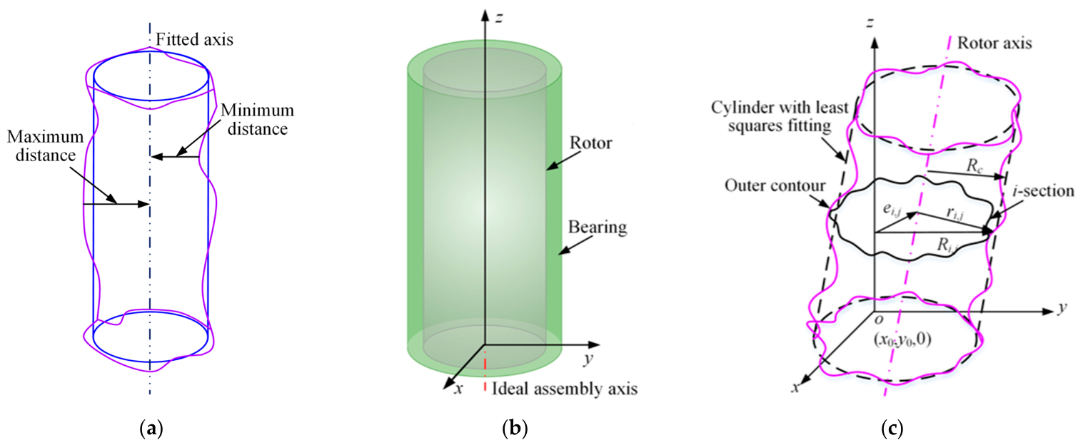
Figure 1a shows one of the standard measurement methods of cylindricity errors. The rotor is measured within a group of parallel circular contour lines, and based on the measured data, the axis of the rotor is fitted. The maximum difference between the distances from the points on the rotor contour to the fitted axis is the cylindricity error [26]. However, due to the existence of rotor manufacturing errors, when the rotor and the bearing fit, their axes do not coincide, that is, the rotor axis deviates from the assembly axis of the two components, as shown in Figure 1b. Therefore, this paper proposes an evaluation method for rotor cylindricity errors based on the rotor–bearing mating state.
As shown in Figure 1c, firstly, the actual axis of the manufactured rotor is determined, and the cylindricity errors ERRORCYLT are evaluated based on this axis. And then, taking the coordinate axes xyz as the reference, a coordinate transformation is performed against the rotor axis to make the rotor and the bearing axis coincide; meanwhile, a coordinate transformation is performed on error ERRORCYLT. Ultimately, the cylindricity errors of rotors are obtained under the rotor–bearing mating state. Among them, Rc is the least square cylinder radius of the i-th section of rotors considering cylindricity errors; ri,j is the distance from the j-th sampling point of the ith section; Ri,j is distance from the j-th sampling point of the ith section to the z-axis of rotors; ei,j is distance from the axis of the ith section to the z-axis of rotors.
The rotor axis can be expressed with a fixed point (x0,y0,0) and the direction a, b corresponding to the axis. The coordinates of the measured point on the i-th section can be expressed as follows:
x i = x 0 + a z i y i = y 0 + b z i z i = z i
The objective function can be expressed as follows:
f ( x 0 , y 0 , a , b , R c ) = min i = 1 m j = 1 n ( r i , j R c ) 2   = min i = 1 m j = 1 n R i , j ( x 0 + a z i ) cos θ i , j ( y 0 + b z i ) sin θ i , j R c 2
According to the Lagrange multiplier method, Equation (3) is obtained:
f x 0 = 0 f y 0 = 0 f a = 0 f b = 0     f R c = 0
The matrix expression of the rotor axis is obtained based on the equations above:
A X   =   B
The distance from the points on the cylindricity surface to the rotor axis is calculated as follows:
d i , j = ( x i , j cos θ i , j x 0 ) 2 + ( y i , j sin θ i , j y 0 ) 2 Ω Ω = a ( x i , j cos θ i , j x 0 ) + b ( y i , j sin θ i , j y 0 ) + z i , j 2 a 2 + b 2 + 1
Equation (4) is solved using the Gauss–Seidel iterative method, and the parameter X can be obtained. The iteration process is considered convergent when the relative error between two successive iterations is less than a predefined tolerance 10−6,or when the maximum number of iterations reaches 1000. Then the maximum distance dmax and the minimum distance dmin from the point on the cylindricity surface to the axis were obtained; finally, the cylindricity errors ERRORCYLT are as follows:
E R R O R C Y L T = d m a x d m i n
According to parameters X, the fixed point (x0,y0,0) and the direction (a,b,1), the direction angles α, β, γ of the rotor axis in the x, y, and z direction, respectively, are as follows:
α = arccos a a 2 + b 2 + 1 β = arccos b a 2 + b 2 + 1 γ = arccos 1 a 2 + b 2 + 1
Then, the translational coordinate equation of rotors is as follows:
T r a n s ( x 0 , y 0 , 0 ) = 1 0 0 x 0 0 1 0 y 0 0 0 1 0 0 0 0 1
The coordinate transformation matrices for the rotor rotating around the x and z axes, respectively, are as follows:
R o t ( x , γ ) = 1 0 0 0 0 cos α sin α 0 0 sin α cos α 0 0 0 0 1 R o t ( z , γ ) = cos γ sin γ 0 0 sin γ cos γ 0 0 0 0 1 0 0 0 0 1
The rotor cylindricity errors R* with the coordinate transformation is as follows:
R = T r a n s ( x 0 , y 0 , 0 ) R o t ( z , γ ) R o t ( x , α ) R
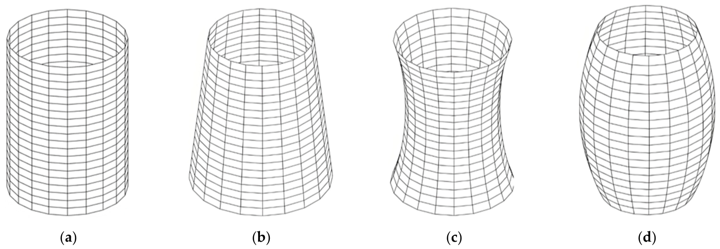
As shown in Figure 2, the overall axial manufacturing error shapes of rotors are generally categorized into conical, saddle and bucket shapes [27].
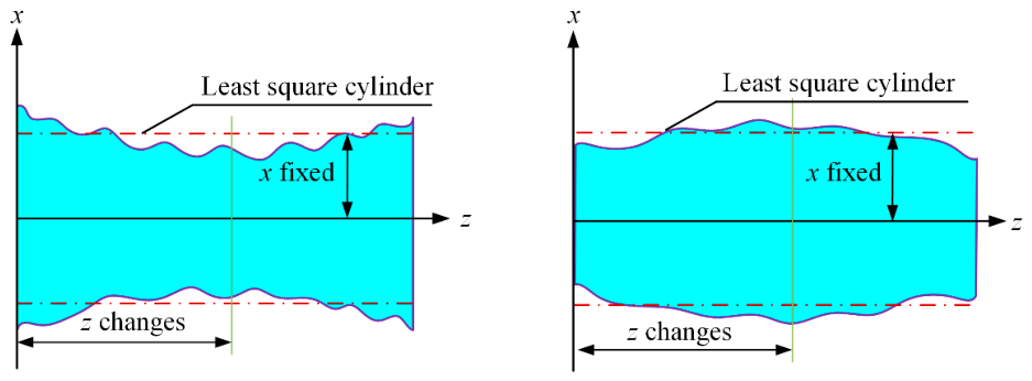
As shown in Figure 3, for the saddle-shaped error and bucket-shaped error, when the minimal or maximal value keep constant, as the measurement position changes in the z direction, that is, with the position of the maximal or minimal value of the distance from the sampling point to the rotor axis changes, the influence of cylindricity errors on the thickness and uniformity of the air film will change. For conical-shaped errors, the particularity of the shape determines that the extreme value position will not change.
When the rotor cylindricity errors are not taken into account, the air film thickness h at any position is as follows [28]:
h i = h 0 + e cos θ
where h0 is the initial air film thickness, e is the eccentricity distance, and θ is the position angle of rotors.
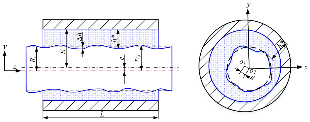
The distribution of the air film thickness when the rotor cylindricity errors are considered is shown in Figure 4. The errors lead to changes in the consistency of the air film thickness when the rotor and bearing are mated, thereby affecting the pressure distribution of this system, and ultimately influencing the dynamic–static characteristics of this system. Under these working conditions, the expression of the air film thickness is as follows:
h = h + Δ h Δ h = r i , j R c
where h* is the air film thickness when rotor cylindricity errors are considered; Δh is the difference in the air film thickness.
Based on the Equations (11) and (12), the air film thickness when rotor cylindricity errors are considered is as follows:
h = h 0 + e cos θ ( r i , j R c )
When the initial film thickness h0 and the eccentricity distance e are known, the distribution of the air film thickness in the ideal working state can be obtained. According to the measured data of rotor cylindricity errors, the rotor radius ri,j, and the least squares radius Rc will be obtained, and ultimately, the distribution of the air film thickness when rotor cylindricity errors are considered is calculated.

3. Establishment and Solution of Dynamic Reynolds Equations Considering Rotor Cylindricity Errors

3.1. Establishment of Dynamic Reynolds Equations Considering Rotor Cylindricity Errors

The flow of the internal flow field of the aerostatic bearing satisfies the Navier–Stokes equation, but this equation is nonlinear and difficult to solve; therefore, the equation needs to be simplified by setting assumptions [29]: (1) Influence of volumetric forces such as gravity is ignored; (2) There is no sliding velocity as the air flows on the interface; (3) The changes in pressure and flow velocity along the direction of the air film thickness is ignored due to the small air film thickness; (4) The air film thickness is relatively small compared to the bearing radius, therefore the influence of the working surface curvature is ignored; (5) The air is Newtonian fluid and its flow mode is laminar; (6) During the working process, the system is in an isothermal state; therefore, the viscosity coefficient remains unchanged. Based on the assumptions above, by combining the gas momentum equation [30], continuity equation [31], and state equation [32], the Reynolds equation at the throttle orifice is obtained [33]:
x p h 3 p x + z p h 3 p z = 6 η U 0 p h x + 12 η ( p h ) t
For the accuracy of the iterative results, Equation (14) needs to be dimensionless:
X ( H 3 P 2 X ) + ψ Z ( H 3 P 2 Z ) + Q δ k = Λ P H X
where x = x 0 X , z = z 0 Z , h = h 0 H , t = τ x 0 u , p = p a P , ψ = x 0 2 z 0 2 , Λ = 12 η u x 0 p a h 0 2 , Q = 24 η x 0 2 ρ a p a h 0 3 ρ V i n , δ k = 1 at the throttled orifice and δ k = 0 without the throttled orifice.
Based on the finite difference method, the partial differential equation of Equation (16) is obtained:
E i , j P i , j 2 + F i , j P i , j I i , j = 0
Then, the air film pressure can be expressed as follows:
P i , j = F i , j 2 + 4 E i , j I i , j F i , j 2 E i , j
where  E i , j = A i , j + B i , j + C i , j + D i , j , F i , j = Λ ( H i + 1 , j H i 1 , j ) 2 Δ X , G i , j = Λ H i , j 2 Δ X , I i , j = A i , j P i + 1 , j 2 + B i , j P i 1 , j 2 + C i , j P i , j + 1 2 + D i , j P i , j 1 2 + Q δ k G i , j ( P i + 1 , j P i 1 , j ) , A i , j = ( H i , j + H i + 1 , j ) 3 8 Δ X 2 , B i , j = ( H i , j + H i 1 , j ) 3 8 Δ X 2 , C i , j = ψ ( H i , j + H i , j + 1 ) 3 8 Δ Z 2 , D i , j = ψ ( H i , j + H i , j 1 ) 3 8 Δ Z 2 .
The pressure Pi,j is solved by the successive over-relaxation iteration:
P i , j = k P i , j + ( 1 k ) P k i , j
where k is the adjustment coefficient, taking the value of 0–1, and Pki,j is the previous iteration pressure.
When the error between two consecutive iterations is less than 10−6, the iteration ends, and the static pressure P0 under the stable state is obtained.
The spindle mode can be decomposed into the basic motion and perturbation motion. When the spindle runs stably at a certain speed, the perturbation displacements (Δxr, Δyr) and the perturbation velocities (ΔXperturbation, ΔYperturbation) determine the air film pressure and air film thickness. The dimensionless displacement of the rotor after applying a small disturbance at the steady-state position (x0, y0) is expressed as follows:
Δ X p e r t u r b a t i o n = Δ x p e r t u r b a t i o n h 0 = Δ X p e r t u r b a t i o n e i ω t = Δ X p e r t u r b a t i o n e i τ Δ Y p e r t u r b a t i o n = Δ y p e r t u r b a t i o n h 0 = Δ Y p e r t u r b a t i o n e i ω t = Δ Y p e r t u r b a t i o n e i τ
The first- and second-order derivatives of Equation (19) are as follows:
Δ X ˙ perturbation = Δ X perturbation τ = i Δ X perturbation e i τ = i Δ X perturbation Δ Y ˙ perturbation = Δ Y perturbation τ = i Δ Y perturbation e i τ = i Δ Y perturbation Δ X ¨ perturbation = Δ X ˙ perturbation τ = i 2 Δ X perturbation e i τ = Δ X perturbation Δ Y ¨ perturbation = Δ Y ˙ perturbation τ = i 2 Δ Y perturbation e i τ = Δ Y perturbation
According to Taylor’s formula, the first-order Taylor expansion of the perturbed air film pressure P and air film thickness H is as follows:
P = P 0 + P X Δ X + P X ˙ Δ X ˙ + P Y Δ Y + P Y ˙ Δ Y ˙ H = H 0 + H X Δ X + H X ˙ Δ X ˙ + H Y Δ Y + H Y ˙ Δ Y ˙
Taking the derivative of Equation (21) and combining it with Equation (15), the Reynolds equation with the perturbation term is obtained.
The perturbation equation with respect to ΔX is as follows:
X ( 2 H 0 3 P 0 X P X + 3 H 0 2 H X P 0 2 X + 2 H 0 3 P X X P 0 ) + ψ Z ( 2 H 0 3 P 0 Z P X + 3 H 0 2 H X P 0 2 Z + 2 H 0 3 P X Z P 0 ) + Q δ k = Λ X ( P 0 H X + P X H 0 ) 2 Λ ( P 0 H X ˙ + P X ˙ H 0 )
The perturbation equation with respect to Δ X ˙ is as follows:
X ( 2 H 0 3 P 0 X P X ˙ + 3 H 0 2 H X ˙ P 0 2 X + 2 H 0 3 P X ˙ X P 0 ) + ψ Z ( 2 H 0 3 P 0 Z P X ˙ + 3 H 0 2 H X ˙ P 0 2 Z + 2 H 0 3 P X ˙ Z P 0 ) + Q δ k = Λ X ( P 0 H X ˙ + P X ˙ H 0 ) + 2 Λ ( P 0 H X + P X H 0 )
The perturbation equation with respect to Δ Y is as follows:
X ( 2 H 0 3 P 0 X P Y + 3 H 0 2 H Y P 0 2 X + 2 H 0 3 P Y X P 0 ) + ψ Z ( 2 H 0 3 P 0 Z P Y + 3 H 0 2 H Y P 0 2 Z + 2 H 0 3 P Y Z P 0 ) + Q δ k = Λ X ( P 0 H Y + P Y H 0 ) 2 Λ ( P 0 H Y ˙ + P Y ˙ H 0 )
The perturbation equation with respect to Δ Y ˙ is as follows:
X ( 2 H 0 3 P 0 X P Y ˙ + 3 H 0 2 H Y ˙ P 0 2 X + 2 H 0 3 P Y ˙ X P 0 ) + ψ Z ( 2 H 0 3 P 0 Z P Y ˙ + 3 H 0 2 H Y ˙ P 0 2 Z + 2 H 0 3 P Y ˙ Z P 0 ) + Q δ k = Λ X ( P 0 H Y ˙ + P Y ˙ H 0 ) + 2 Λ ( P 0 H Y + P Y H 0 )

3.2. Solution of Dynamic Reynolds Equations Considering Rotor Cylindricity Errors

The dynamic perturbation Reynolds with regard to ΔX is discretized using the finite difference method, and combining Equations (21) and (22), Equation (26) is obtained:
A X ( i , j ) P X ( i + 1 , j ) + B X ( i , j ) P X ( i 1 , j ) + C X ( i , j ) P X ( i , j + 1 ) + D X ( i , j ) P X ( i , j 1 ) E X ( i , j ) P X ( i , j ) + F X ( i , j ) = 0 P X ( i , j ) = G X ( i , j ) E X ( i , j )
where
A X ( i , j ) = ( H 0 ( i , j ) + H 0 ( i + 1 , j ) ) 3 P 0 ( i + 1 , j ) 4 Δ X 2 Λ ( H 0 ( i , j ) + H 0 ( i + 1 , j ) ) 4 Δ X B X ( i , j ) = ( H 0 ( i , j ) + H 0 ( i 1 , j ) ) 3 P 0 ( i 1 , j ) 4 Δ X 2 + Λ ( H 0 ( i , j ) + H 0 ( i 1 , j ) ) 4 Δ X C X ( i , j ) = Ψ ( H 0 ( i , j ) + H 0 ( i , j + 1 ) ) 3 P 0 ( i , j + 1 ) 4 Δ Z 2 D X ( i , j ) = Ψ ( H 0 ( i , j ) + H 0 ( i , j 1 ) ) 3 P 0 ( i , j 1 ) 4 Δ Z 2 E X ( i , j ) = ( H 0 ( i , j ) + H 0 ( i + 1 , j ) ) 3 P 0 ( i , j ) 4 Δ X 2 + ( H 0 ( i , j ) + H 0 ( i 1 , j ) ) 3 P 0 ( i , j ) 4 Δ X 2   + Ψ ( H 0 ( i , j ) + H 0 ( i , j + 1 ) ) 3 P 0 ( i , j ) 4 Δ Z 2 + Ψ ( H 0 ( i , j ) + H 0 ( i , j 1 ) ) 3 P 0 ( i , j ) 4 Δ Z 2   + Λ ( H 0 ( i , j ) + H 0 ( i + 1 , j ) ) 4 Δ X Λ ( H 0 ( i , j ) + H 0 ( i 1 , j ) ) 4 Δ X
F X ( i , j ) = 3 ( H 0 ( i , j ) + H 0 ( i + 1 , j ) ) 2 ( H X ( i , j ) + H X ( i + 1 , j ) ) ( P 0 ( i + 1 , j ) P 0 ( i , j ) 2 ) 8 Δ X 2 3 ( H 0 ( i , j ) + H 0 ( i 1 , j ) ) 2 ( H X ( i , j ) + H X ( i 1 , j ) ) ( P 0 ( i , j ) 2 P 0 ( i 1 , j ) 2 ) 8 Δ X 2   + 3 ψ ( H 0 ( i , j ) + H 0 ( i , j + 1 ) ) 2 ( H X ( i , j ) + H X ( i , j + 1 ) ) ( P 0 ( i , j + 1 ) 2 P 0 ( i , j ) 2 ) 8 Δ Z 2 3 ψ ( H 0 ( i , j ) + H 0 ( i , j 1 ) ) 2 ( H X ( i , j ) + H X ( i , j 1 ) ) ( P 0 ( i , j ) 2 P 0 ( i , j 1 ) 2 ) 8 Δ Z 2 + Q δ i   Λ ( P 0 ( i , j ) + P 0 ( i + 1 , j ) ) ( H X ( i , j ) + H X ( i + 1 , j ) ) ( P 0 ( i , j ) + P 0 ( i 1 , j ) ) ( H X ( i , j ) + H X ( i 1 , j ) ) 4 Δ X   + 2 Λ ( P 0 ( i , j ) H X ˙ ( i , j ) + P X ˙ ( i , j ) H 0 ( i , j ) ) G X ( i , j ) = A X ( i , j ) P X ( i + 1 , j ) + B X ( i , j ) P X ( i 1 , j ) + C X ( i , j ) P X ( i , j + 1 ) + D X ( i , j ) P X ( i , j 1 ) + J X ( i , j )
Similarly, the perturbation pressure about Δ X ˙ can be expressed as follows:
P X ˙ ( i , j ) = G X ˙ ( i , j ) E X ˙ ( i , j )
where the coefficients F X ˙ ( i , j ) and G X ˙ ( i , j ) are different from those in Equation (28), and their expressions are as follows:
F X ˙ ( i , j ) = 3 ( H 0 ( i , j ) + H 0 ( i + 1 , j ) ) 2 ( H X ˙ ( i , j ) + H X ˙ ( i + 1 , j ) ) ( P 0 ( i + 1 , j ) 2 P 0 ( i , j ) 2 ) 8 Δ X 2 3 ( H 0 ( i , j ) + H 0 ( i 1 , j ) ) 2 ( H X ˙ ( i , j ) + H X ˙ ( i 1 , j ) ) ( P 0 ( i , j ) 2 P 0 ( i 1 , j ) 2 ) 8 Δ X 2   + 3 ψ ( H 0 ( i , j ) + H 0 ( i , j + 1 ) ) 2 ( H X ˙ ( i , j ) + H X ˙ ( i , j + 1 ) ) ( P 0 ( i , j + 1 ) 2 P 0 ( i , j ) 2 ) 8 Δ Z 2 3 ψ ( H 0 ( i , j ) + H 0 ( i , j 1 ) ) 2 ( H X ˙ ( i , j ) + H X ˙ ( i , j 1 ) ) ( P 0 ( i , j ) 2 P 0 ( i , j 1 ) 2 ) 8 Δ Z 2 + Q δ i   Λ ( P 0 ( i , j ) + P 0 ( i + 1 , j ) ) ( H X ˙ ( i , j ) + H X ˙ ( i + 1 , j ) ) ( P 0 ( i , j ) + P 0 ( i 1 , j ) ) ( H X ˙ ( i , j ) + H X ˙ ( i 1 , j ) ) 4 Δ X   2 Λ ( P 0 ( i , j ) H X ( i , j ) + P X ( i , j ) H 0 ( i , j ) ) G X ˙ ( i , j ) = A X ˙ ( i , j ) P X ˙ ( i + 1 , j ) + B X ˙ ( i , j ) P X ˙ ( i 1 , j ) + C X ˙ ( i , j ) P X ˙ ( i , j + 1 ) + D X ˙ ( i , j ) P X ˙ ( i , j 1 ) + J X ˙ ( i , j )
Similarly, the perturbation pressure to Δ Y and Δ Y ˙ are solved.
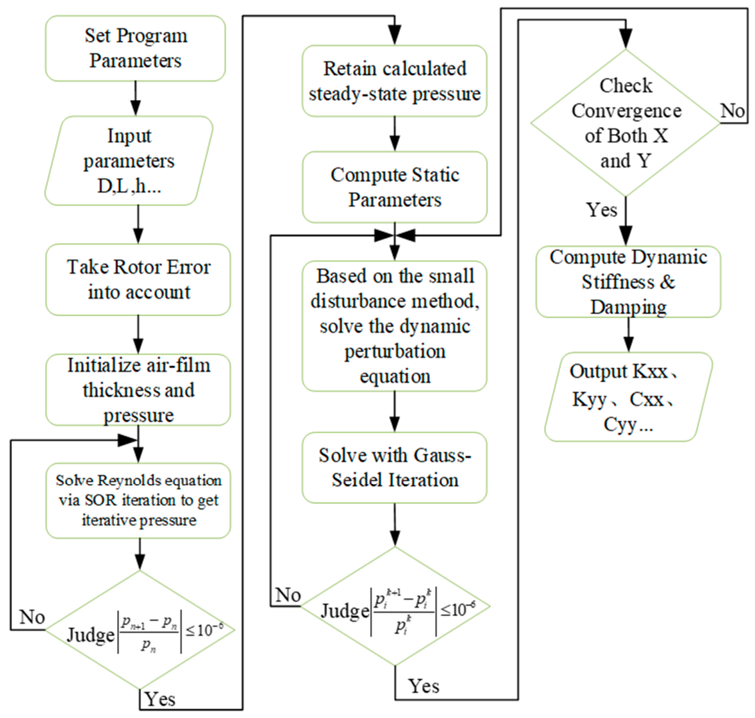
Equation (22) contains both P X and P X ˙ , which need to be solved jointly with Equation (23). During the coupling process, by adjusting the initial values of P X and P X ˙ , the iteration will not end until both meet the convergence conditions. Similarly, P Y and P Y ˙ can be calculated. The specific solving process is shown in Figure 5.

3.3. Calculation of Dynamic Stiffness Coefficients and Dynamic Damping Coefficients

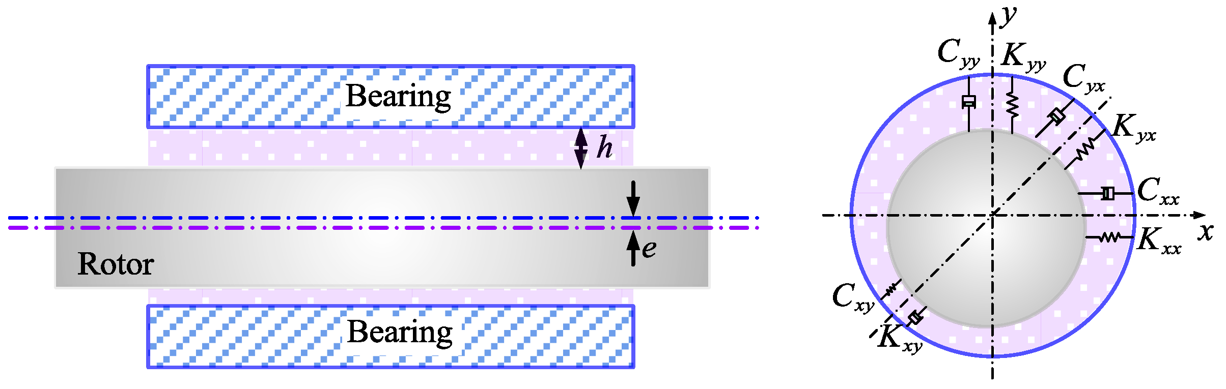
In the dynamic characteristic analysis of aerostatic spindles, by solving the dynamic stiffness coefficient and dynamic damping coefficient, the working stability of spindles and the safe rotational speed of rotors are analyzed and characterized. Generally speaking, the dynamic effect of the air film can be translated into four stiffness coefficients and four damping coefficients in the linear range, as shown in Figure 6 [34]. The air film plays the nonlinear spring and damping role in the working condition. However, in the whole operation of bearings, the perturbation amplitude is small; therefore, the air film can be approximated as the linearized spring and damping, thereby simplifying the calculation.
Δ F x Δ F y = K x x K x y K y x K y y x y + C x x C x y C y x C y y x ˙ y ˙
Based on Equation (31), the dynamic stiffness coefficient is obtained by integrating  P X , P X ˙ , P Y and P Y ˙ :
K X X K Y X K X Y K Y Y = p a x o z 0 h o D P X sin θ P X cos θ P Y sin θ P Y cos θ d s
Similarly, the dynamic damping coefficient is as follows:
C X X C Y X C X Y C Y Y = p a x o z 0 ω h o D P X ˙ sin θ P X ˙ cos θ P Y ˙ sin θ P Y ˙ cos θ d s

4. Analysis of the Effect of Cylindricity Errors on Dynamic Stiffness and Damping Coefficients

4.1. Effect of Error Shapes on Dynamic Stiffness Coefficients

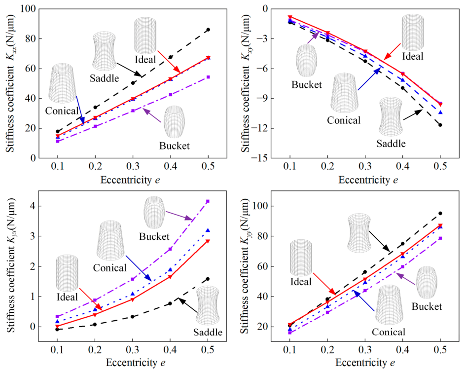
When the air supply pressure is 0.4 MPa and the cylindricity errors are 2.5 μm, the dynamic stiffness coefficient changes with the eccentricity; the cylindricity error shapes are shown in Figure 7. With different error shapes, the main stiffness coefficients Kxx and Kyy both increase with the increase of eccentricity. The reason for this phenomenon is that the hydrodynamic effect in bearings–rotor systems is gradually enhanced with the increase of the eccentricity. Under the specific eccentricity, the main stiffnesses Kxx and Kyy are both more sensitive to the saddle-shaped error, followed by conical-shaped errors, and, finally, bucket-shaped errors. It can be seen that the absolute values of the cross stiffness coefficients Kxy and Kyx increase with the increase in the eccentricity. The cross stiffness Kxy (Kxy < 0) is more sensitive to saddle-shaped errors; the cross stiffness Kyx (Kyx > 0) is sensitive to bucket-shaped errors. The quantitative analysis shows that the cross stiffness coefficients are smaller than the main stiffness coefficients, which is due to the fact that the horizontal force caused by the hydrodynamic effects is less than the vertical force generated by the hydrodynamic effects. Therefore, the cylindricity errors of rotors should be reasonably controlled according to different working conditions to ensure optimal performance.

4.2. Effect of Errors Extremal Positions on Dynamic Stiffness Coefficients

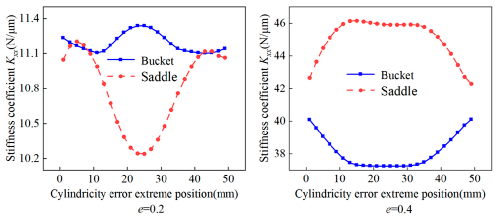
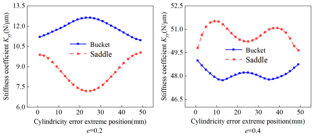
Figure 8 and Figure 9 show the variation of the dynamic stiffness coefficient with the extremal positions of cylindricity errors, keeping the air supply pressure (0.4 MPa) and cylindricity error value (2.5 μm) constant. As shown in parts of Figure 8, when the eccentricity is 0.2, for the bucket-shaped error, as the error’s extremal position changes, the main stiffness coefficient Kxx fluctuates in a wave shape, and the amplitude is relatively small. For the saddle-shaped error, the trend of the coefficient Kxx with the change of the error’s extremal positions is the same as that of the coefficient Kxx, but the fluctuation amplitude is relatively large. Under the influence of the bucket-shaped error, the coefficient Kyy increases first and then decreases with the error extremal positions; however, the changing trend of the coefficient Kyy is opposite under the influence of the saddle-shaped error. Parts of Figure 8 show that when the eccentricity is 0.4, coefficients Kxx and Kyy both fluctuate periodically with the change of the errors’ extremal positions under the effect of two kinds of error shapes; the fluctuation amplitude of the coefficient Kxx is larger than that of the coefficient Kyy. The analysis above demonstrates that when the eccentricity is small and the error shape is saddle, the error’s extremal positions have a larger effect on the main stiffness; as the eccentricity increases, under the effect of both kinds of error shapes, the difference in the impact of the errors’ extremal positions on the main stiffness becomes smaller.
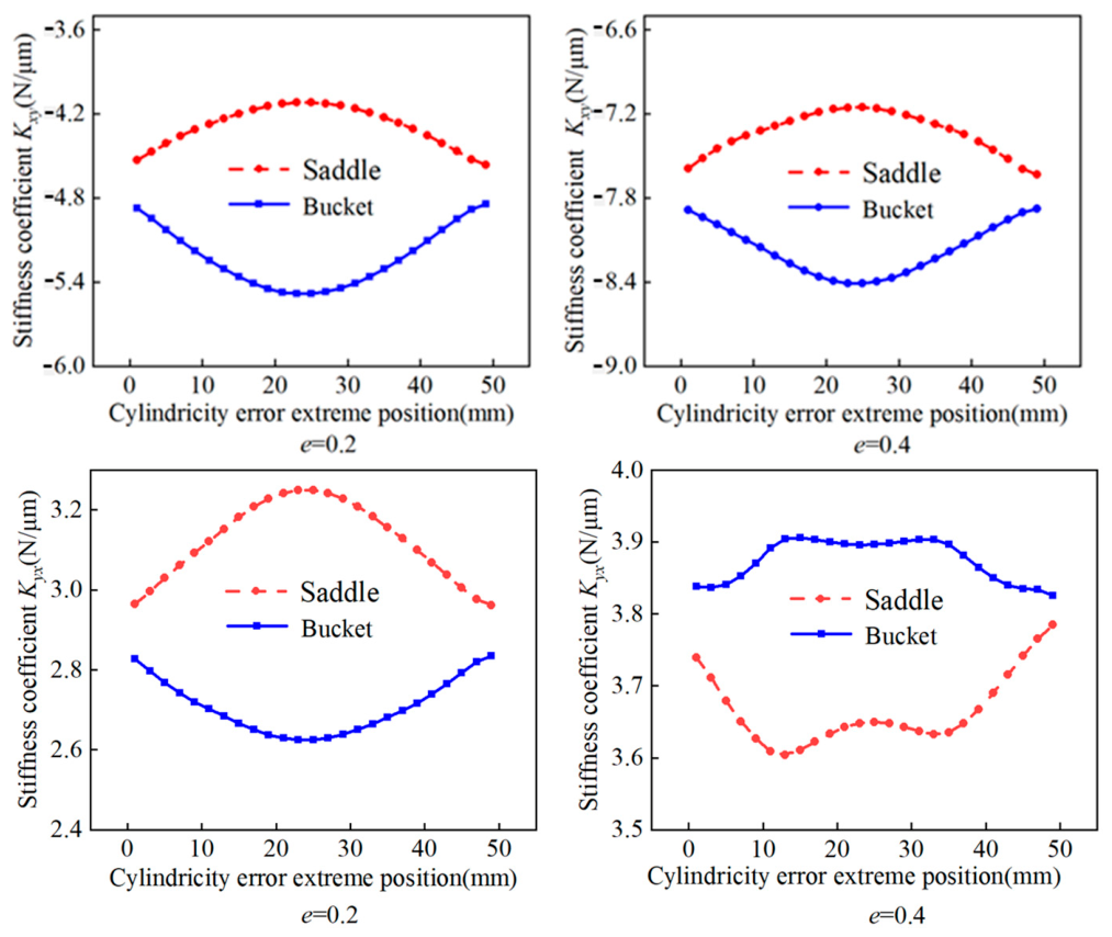
In parts of Figure 9, when the eccentricity is 0.2 and the error shape is bucket, the cross stiffness coefficient (Kxy < 0) first decreases and then increases with the error’s extremal position changes; when the saddle-shaped error exists, the change trend of the coefficient Kxy is opposite. When both kinds of error shapes exist, the change trend of the coefficient Kyx (Kyx < 0) is the same as that of the Kxy. As the eccentricity increases to 0.4, as shown in parts of Figure 9, when both kinds of error shapes exist, the changing trend of the coefficient Kxy (Kxy < 0) is the same as that when the eccentricity is 0.2; however, the change in the coefficient Kyx (Kyx < 0) is relatively complex and exhibits a complex, non-monotonic variation trend along the axial direction. In general, the effect of cylindricity error’s extremal positions on the cross stiffness is small; that is, the cross stiffness is not sensitive to the cylindricity error’s extremal positions.

4.3. Effect of Error Values on Dynamic Stiffness Coefficients

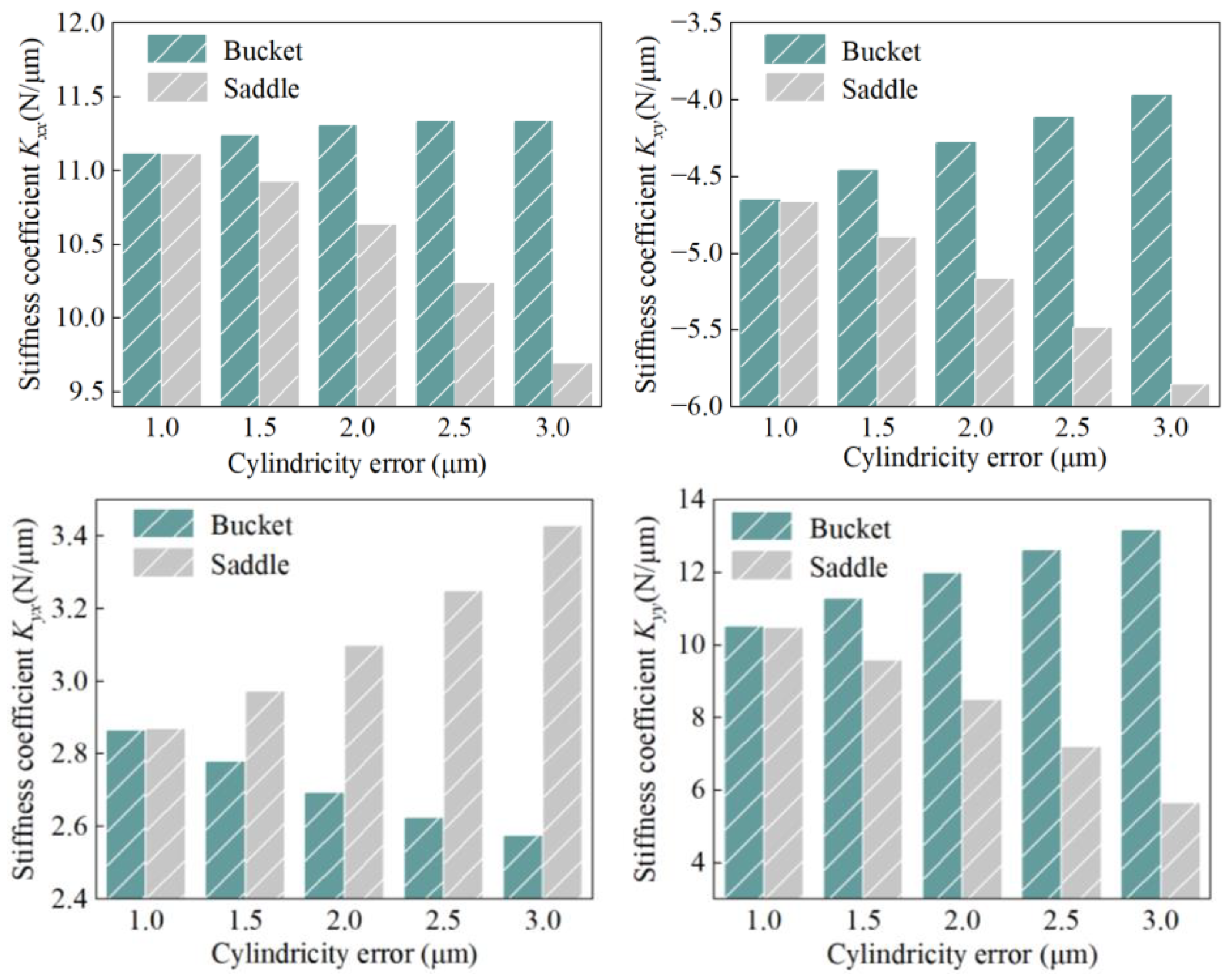
All the results are from deterministic numerical simulations. A grid independence study ensured numerical convergence. The analysis of cylindricity error magnitude also serves as a sensitivity assessment of this key parameter. The effect of cylindricity error magnitude on the dynamic stiffness coefficients is shown in Figure 10. When the error magnitude is less than 1 μm, the difference in dynamic stiffness coefficients between bucket-shaped and saddle-shaped errors is small. When the error values are between 1 μm and 3 μm, the main stiffness coefficients Kxx and Kyy in the presence of bucket-shaped errors both increase with the growth of error values, but the increase magnitude is small; the coefficients Kxx and Kyy in the presence of saddle-shaped errors both decrease with the increase of error values, and the larger the error values, the faster the coefficient decreases. When the bucket-shaped errors exist, the absolute values of the cross stiffness coefficients Kxy and Kyx decrease with the increase in error values; when the saddle-shaped errors exist, the absolute values of the coefficients Kxy and Kyx increase with the growth of error values, and the increase magnitude is large. The changes in the two stiffness coefficients indicate that the cross stiffness is smaller than the main stiffness; therefore, more consideration should be given to the influence of the main stiffness on the spindle performance under the actual working condition. Meanwhile, the saddle-shaped errors are not conducive to the improvement of the main stiffness. Overall, the results indicate that the rotor cylindricity errors should be controlled below 1 μm to maintain high dynamic stiffness, and saddle-shaped errors are unfavorable for main stiffness and should be avoided.

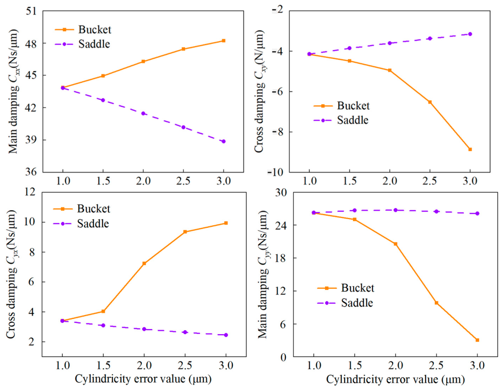
4.4. Effect of Error Shapes on Dynamic Damping Coefficients

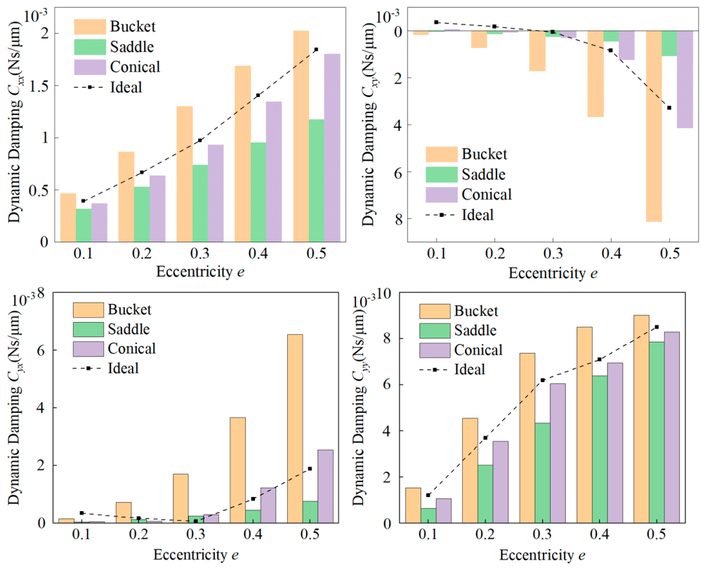
The eccentricity ratio was varied from 0.1 to 0.5 in our study, covering both light and moderate loading conditions typical of aerostatic spindle applications. At higher ratios (>0.5), the air film thickness becomes excessively small, leading to potential numerical convergence issues and practical operating limits, hence, not considered here. When the air supply pressure is 0.4 MPa and the cylindricity errors are 2.5 μm, the change in the dynamic damping coefficient with the eccentricity and cylindricity error shapes is shown in Figure 11. Across all three error profiles, the direct damping coefficients Cxx and Cyy increase monotonically with eccentricity ratio, attributed to the intensified squeeze-film effect as the air film thickness reduces. In contrast to hydrodynamic bearings, the externally pressurized aerostatic bearing in this study exhibits consistently increasing damping behavior rather than the non-monotonic trends observed in pure hydrodynamic systems. When the eccentricity remains fixed, for example, with an eccentricity of 0.3, the coefficient Cxx is about 9 N·s/m under ideal conditions; for the conical-shaped error, the coefficient Cxx is 13.1 N·s/m; for the bucket-shaped error, the coefficient Cxx is 6.89·N·s/m. The quantitative characterization above shows that bucket-shaped errors have the most significant effect on the main damping, followed by conical-shaped errors, and finally saddle-shaped errors. The absolute values of the cross damping coefficients Cxy (Cxy < 0) and Cyx (Cyx > 0) increase with the growth of the eccentricity, and they are more sensitive to the bucket-shaped error.

4.5. Effect of Errors’ Extremal Positions on Dynamic Damping Coefficients

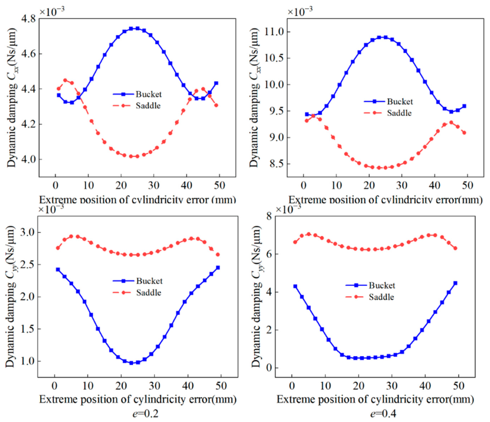
Figure 12 and Figure 13 display the effect of cylindricity errors’ extremal positions on the main and cross dynamic damping coefficients. As shown in Figure 12, when the eccentricity keeps constant, the main damping coefficient Cxx fluctuates regularly with the change of errors’ extremal positions for the bucket-shaped errors and saddle-shaped errors, but the change trend of the coefficient Cyy for the two kinds of errors is opposite; the fluctuation amplitude of the coefficient Cxx in the presence of the bucket-shaped errors is larger than that of the saddle-shaped error; meanwhile, with the growth of the eccentricity, the change amplitude of the coefficient Cxx increases. For both kinds of error shapes, the change trend of the coefficient Cyy with the errors’ extremal positions is different from that of the Cxx. For the bucket-shaped error, the coefficient Cyy decreases first and then increases with the change of the error’s extremal positions. For the saddle-shaped error, the coefficient Cyy shows regular fluctuation. On the whole, as the errors’ extremal positions change, the two main damping coefficients under the influence of bucket-shaped errors change significantly, and thus, compared with the saddle-shaped error, the main damping under the influence of the bucket-shaped errors is more sensitive to cylindricity errors extremal positions.
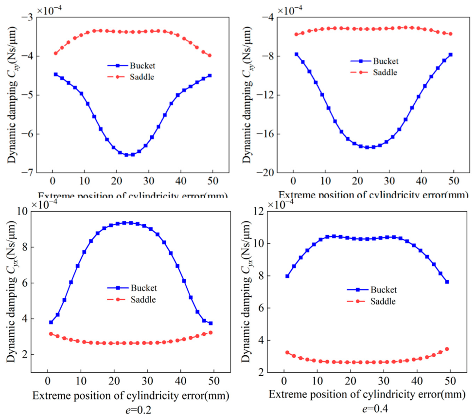
From Figure 13, it can be seen that the cross damping coefficient Cxy (Cxy < 0) varies significantly with the error’s extremal positions under the effect of bucket-shaped errors, showing a trend of decreasing first and then increasing; however, the coefficient Cxy varies relatively flatly under the effect of saddle-shaped errors. As the eccentricity increases, the fluctuation of the coefficient Cxy increases.
At the eccentricity of 0.2 and 0.4, for bucket-shaped errors, the cross damping coefficient Cyx (Cyx > 0) increases first and then decreases with the error’s extremal positions, and the change magnitude is large; under the influence of the saddle-shaped error, the change magnitude of the coefficient Cyx is also relatively small. Similarly, the change magnitude of the coefficient Cxy fluctuates with the error’s extremal positions with the increase in the eccentricity.
The change magnitude of two kinds of coefficients with the errors’ extremal positions indicates that the cross damping is more sensitive to the bucket-shaped error. In summary, Figure 12 and Figure 13 indicate that the main and cross damping are more sensitive to bucket-shaped errors with the change of cylindricity errors extremal positions, so when there is a bucket-shaped error in the rotor, the dynamic damping of the rotor–bearing system can be adjusted by changing the cylindricity error’s extremal positions.

4.6. Effect of Error Values on Dynamic Damping Coefficients

The effect of cylindricity error values on the dynamic damping coefficient is shown in Figure 14, and when the error value is less than 1 μm, the difference in dynamic damping coefficients corresponding to bucket-shaped errors and saddle-shaped errors is small. When the error values is between 1 μm and 3 μm, the main damping coefficient Cxx corresponding to bucket-shaped errors increases with the increase in error values, and the coefficient Cxx corresponding to the saddle-shaped errors decreases with the increase in error values. As the error values change, the growth of the main damping coefficient Cyy is not obvious under the influence of saddle-shaped errors, while the coefficient Cyy under the influence of bucket-shaped errors is relatively obvious, showing an approximate linear decreasing trend. Therefore, with the error values change, the main damping coefficient Cxx is sensitive to the two kinds of error shapes, while the main damping coefficient Cyy is sensitive to bucket-shaped errors. When bucket-shaped errors exist, the absolute values of cross-damping coefficients Cxy and Cyx increase with the growth of error values; when saddle-shaped errors exist, the absolute values of the two kinds of coefficients decrease with the growth of error values. In addition, the analysis above illustrates that when considering the influence of the cylindricity error values on the dynamic damping, the main damping should receive more attention, and the rotor cylindricity error values are less than 1 μm.

5. Experimental Study of the Dynamic Characteristics of Aerostatic Spindles

In order to further investigate the dynamic characteristics of aerostatic spindles considering rotor cylindricity errors, an aerostatic spindle was designed and assembled based on the manufactured rotor, and its radial displacement and rotation accuracy were measured under the working condition using a self-built test platform.

5.1. Experimental Equipment and Methods

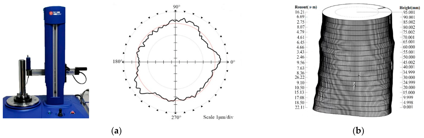
As shown in Figure 15, the cylindricity errors of manufactured rotors were measured based on the circumferential cross-section method using a Talyrond 585LT-500 Cylindricity Gauge, and the measurement accuracy of this cylindricity gauge is described in Table 1. Figure 15a shows the measurement results of a specific section of the manufactured rotors, and Figure 15b shows the measurement results of cylindricity errors of the manufactured rotors.
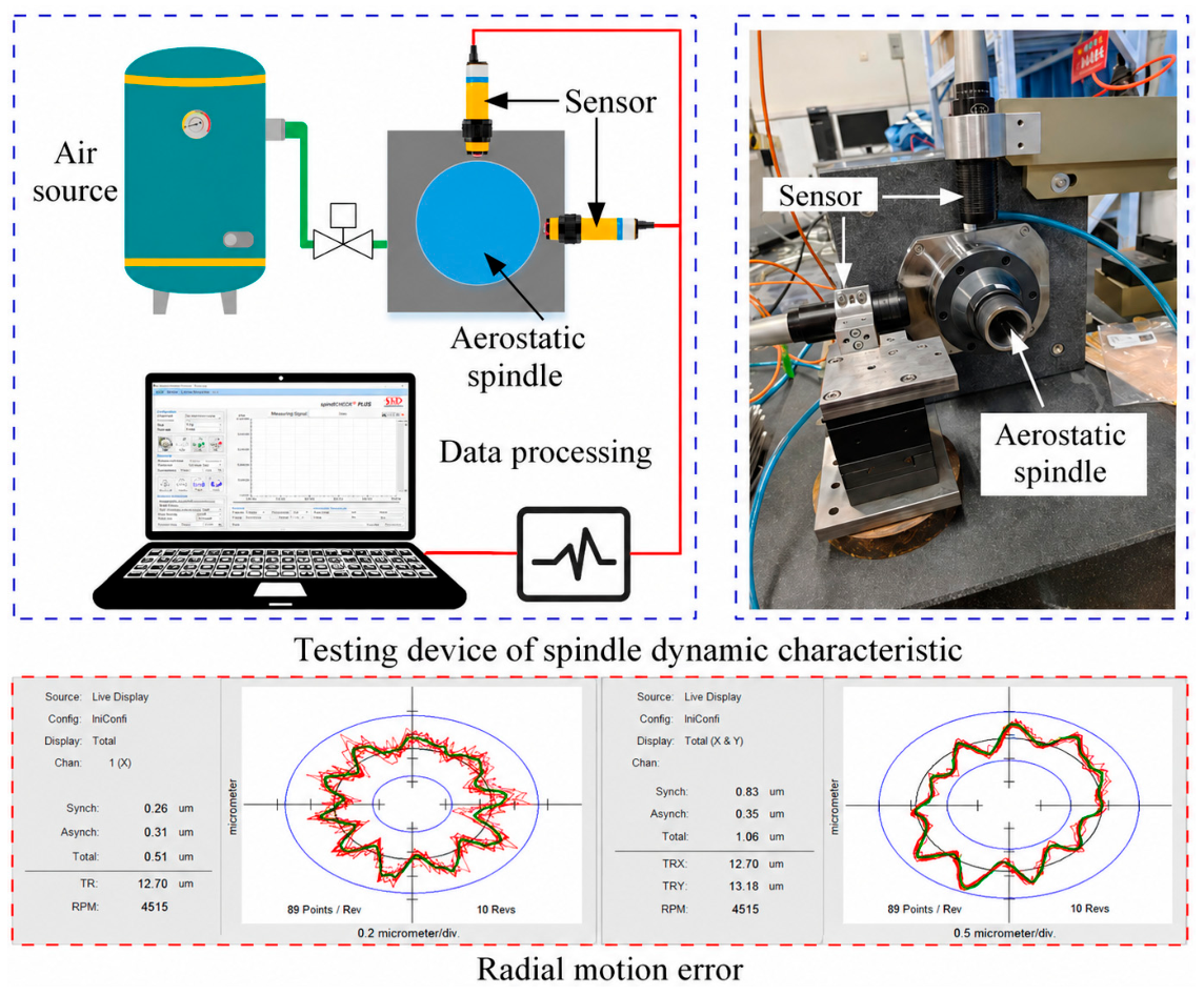
As shown in Figure 16, for characterizing the dynamic characteristics of the aerostatic spindle, the radial displacement and rotary accuracy of the aerostatic spindle were measured on a test platform. The test system mainly consists of an air source, a regulator, the aerostatic spindle, a laser displacement sensor and a data processing device. Among them, the displacement sensor (IFS2405-3, Micro-Epsilon, Ortenburg, Germany) and its controller (IFS2422, Micro-Epsilon, Ortenburg, Germany) were used in the experiments. The air supply pressure was set between 0.4 MPa and 0.6 MPa, and the spindle speed was increased from 2000 rpm to 6000 rpm. Two laser displacement sensors were mounted orthogonally on the spindle housing, facing the spindle nose, within the sensor’s calibrated measurement range, to collect the data when the aerostatic spindle operated under different air supply pressures and speeds.

5.2. Analysis of Experimental Results

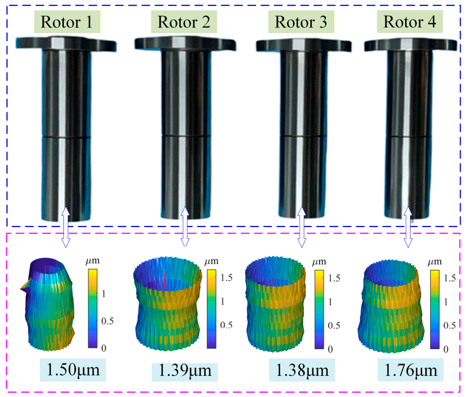
To improve the reliability of the experimental results, each test was repeated three times under the same operating conditions, and the average values were used for subsequent analysis. The cylindricity error shapes and values of the manufactured rotors are shown in Figure 17. Each of the four rotors corresponds to a distinct error shape, thus enabling the investigation of the influence of cylindricity error shapes on the dynamic characteristics of aerostatic spindles. Additionally, their error values are different, which also allows for the study of the effect of cylindricity error values on the dynamic characteristics of aerostatic spindles.
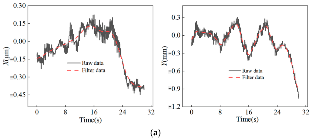
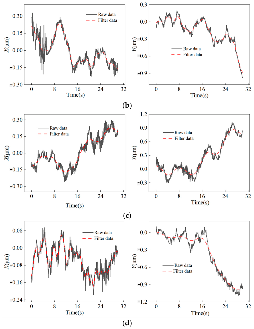
Due to the presence of high-frequency noise in the measured signals, a low-pass filtering method was applied to the raw data. Taking rotor 1 as an example, under air supply pressures of 0.4 MPa and 0.5 MPa and rotational speeds of 4000 rpm and 6000 rpm, the motion trajectories in the X and Y directions are shown in Figure 18.
At an air supply pressure of 0.4 MPa, the fluctuation amplitude in the X direction is approximately 0.42 μm, while that in the Y direction is about 0.96 μm. When the air supply pressure increases to 0.5 MPa, the fluctuation amplitudes in both directions remain at a similar level, indicating stable system performance under different pressures.
For further characterization of the dynamic characteristics of the assembled aerostatic spindle based on different manufactured rotors, the rotation errors of the spindle are shown in Table 2 when the rotation speed is 4000 rpm and the air supply pressure is 0.5 MPa. The results presented in Table 3 are averaged values from repeated measurements, showing good consistency among the experimental data.
Figure 17 shows that among the assembled spindles, Spindle 4, with the highest cylindricity error (1.76 μm), exhibits the largest rotation error, while Spindles 1–3, with lower errors, show correspondingly higher rotational accuracy. This proves that the larger the rotor cylindricity errors are, the lower the spindle rotation accuracy is. The observed trend in rotational performance provides indirect but clear experimental validation of the theoretical findings: as the cylindricity error increases, the resulting changes in the air film geometry alter the dynamic stiffness and damping characteristics of the rotor–bearing system, which in turn directly affect the spindle’s rotational accuracy. Therefore, the characterization of rotation errors in the assembled aerostatic spindle indirectly verifies the theoretical analysis results that the dynamic stiffness coefficient and the dynamic damping coefficient of the rotor–bearing system change with the cylindricity error values.
Overall, the experimental data exhibit good repeatability and consistency, supporting the validity of the theoretical analysis.

6. Conclusions

In this study, the dynamic stiffness and damping coefficients of aerostatic spindles considering rotor cylindricity errors were investigated through theoretical modeling and experimental validation. The main conclusions are summarized as follows:
(1)
A dynamic model considering rotor cylindricity errors was established based on the rotor–bearing mating state and modified air-film thickness distribution. The results show that cylindricity error shape significantly affects the dynamic coefficients of the rotor–bearing system. Among the investigated error profiles, saddle-shaped errors have the strongest influence on the main stiffness coefficients Kxx and Kyy, while bucket-shaped errors mainly affect the damping coefficients and cross stiffness coefficient Kyx.
(2)
The extremal position and magnitude of cylindricity errors further change the dynamic characteristics of the spindle system. When the cylindricity error exceeds 1 μm, the main stiffness coefficients decrease significantly under saddle-shaped errors, whereas the damping coefficients become more sensitive to bucket-shaped errors. In contrast, when the error magnitude is below 1 μm, the variations of stiffness and damping coefficients remain relatively small, indicating more stable rotor–bearing dynamic performance.
(3)
Under the condition of 0.4 MPa air supply pressure and 2.5 μm cylindricity error, the direct damping coefficient Cxx changes from approximately 9 N·s/m in the ideal state to 13.1 N·s/m for conical-shaped errors and 6.89 N·s/m for bucket-shaped errors, demonstrating that different error morphologies lead to significantly different air-film dynamic behaviors.
(4)
The experimental results agree well with the theoretical analysis. The spindle assembled with the largest cylindricity error (1.76 μm) exhibited the largest rotational error (0.38–0.45 μm), whereas spindles with smaller cylindricity errors showed better rotational accuracy. The results confirm that increasing rotor cylindricity error deteriorates the dynamic stiffness and damping characteristics and consequently reduces spindle rotational accuracy. This study provides theoretical guidance for rotor error tolerance design and dynamic performance optimization of ultra-precision aerostatic spindles. In addition, the obtained dynamic stiffness and damping coefficients provide an important basis for further rotor-dynamics analysis, including natural frequency prediction, critical speed evaluation, and vibration stability assessment of aerostatic spindle systems.

Author Contributions

Conceptualization, W.W. (Wenjing Wu), L.H., W.W. (Wenbo Wang), G.W., G.F., G.Z. and H.Y.; Methodology, W.W. (Wenjing Wu), L.H., W.W. (Wenbo Wang), G.F. and H.Y.; Software, L.H., W.W. (Wenbo Wang), G.W. and G.F.; Validation, L.H. and G.W.; Formal analysis, G.Z.; Investigation, W.W. (Wenbo Wang) and G.W.; Resources, L.H., W.W. (Wenbo Wang), G.W., G.F., G.Z. and H.Y.; Data curation, W.W. (Wenjing Wu), G.W., G.Z. and H.Y.; Writing—original draft, W.W. (Wenjing Wu), W.W. (Wenbo Wang), G.W. and G.F.; Supervision, L.H., G.Z. and H.Y.; Project administration, W.W. (Wenjing Wu) and H.Y.; Funding acquisition, H.Y. All authors have read and agreed to the published version of the manuscript.

Funding

This research was funded by the Henan Provincial Natural Science Foundation of China (Grant No. 262300421425) and the National Natural Science Foundation of China (Grant No. 51875586).

Data Availability Statement

The original contributions presented in this study are included in the article. Further inquiries can be directed to the corresponding author.

Conflicts of Interest

The authors declare no conflicts of interest.

Nomenclature

x , y , z Coordinate components C x x , C y y Direct dynamic damping coefficient in x(y)-direction
E R R O R C Y L T Rotor cylindricity error C x y , C y x Cross dynamic damping coefficient from x(y) to y(x)
R c Least squares cylinder radius of the i-th rotor section P Air film pressure
r i , j Distance from the j-th sampling point to the rotor axis on the i-th section P 0 Steady-state air film pressure
R i , j Distance from the j-th sampling point to the rotor z-axis on the i-th section P i , j  Pi,jDiscretized air film pressure at grid (i,j)
e i , j Distance from the i-th section axis to the rotor z-axis P x , P y Partial derivative of pressure with respect to ΔX(ΔY)
x 0 ,   y 0 Fixed point coordinates of the rotor axis P ˙ x , P ˙ y Partial   derivative   of   pressure   with   respect   to Δ X ( Δ Y )
a , b Direction components of the rotor axis Δ x r , Δ y r Perturbation displacements
d max Maximum distance from cylindricity surface points to the rotor axis Δ X , Δ Y Dimensionless perturbation displacements
d min Minimum distance from cylindricity surface points to the rotor axis Δ X ˙ , Δ Y ˙ Dimensionless perturbation velocities
R Rotor cylindricity error after coordinate transformation μ Gas dynamic viscosity
h 0 Initial air film thickness ρ Gas density
h Air film thickness without cylindricity error p Gas pressure
h Air film thickness considering rotor cylindricity error u , v , w Gas flow velocity components
Δ h Air film thickness difference t Time
e Eccentricity distance ω Rotor angular velocity
θ Rotor circumferential position angle L Bearing length
H Dimensionless air film thickness D Bearing diameter
X Parameter vector for rotor axis fitting C Radial clearance
K x x , K y y Direct dynamic stiffness coefficient in x(y)-direction R x , R z Rotation transformation matrix around x(z)-axis
K x y , K y x Cross dynamic stiffness coefficient from x(y) to y(x)

References

  1. Li, Y.; Huang, W.; Sang, R. Analysis of the Influencing Factors of Aerostatic Bearings on Pneumatic Hammering. Lubricants 2024, 12, 395. [Google Scholar] [CrossRef] [Scilit]
  2. Luo, J.; Cao, Y.; Jin, J.; Liu, F.; Zhi, J. Study on the Rotation Accuracy of Gas Hydrostatic Bearings Based on Skin Model Shapes. Precis. Eng. 2025, 94, 435–446. [Google Scholar] [CrossRef] [Scilit]
  3. Li, Y. Shape Optimization of the Aerostatic Bearing Considering Dynamic Performances. Mechanics 2025, 31, 27–34. [Google Scholar] [CrossRef] [Scilit]
  4. Sun, Z.; Guan, C.; Xu, H.; Hu, H.; Dai, Y. The Influence of Journal’s Roundness on Rotating Accuracy of Aerostatic Spindle and Precision Improvement by Time-Controlled Grinding. Tribol. Int. 2024, 197, 109805. [Google Scholar] [CrossRef] [Scilit]
  5. Lu, H.; Li, C.; Tan, Z.; Hua, C.; Lv, G.; Hao, J.; Song, G. Nonlinear Thermal-Vibration Characteristics Analysis of Aerostatic Spindle Considering Coupling Effect. Int. J. Mech. Sci. 2025, 294, 110260. [Google Scholar] [CrossRef] [Scilit]
  6. Chen, D.J.; Zhang, X.; Sun, K.; Li, T.; Chen, F. Research progress review on macro-micro scale of aerostatic spindle. J. Beijing Univ. Technol. 2023, 49, 577–596. [Google Scholar] [CrossRef]
  7. Gao, Q.; Chen, W.; Lu, L.; Huo, D.; Cheng, K. Aerostatic Bearings Design and Analysis with the Application to Precision Engineering: State-of-the-Art and Future Perspectives. Tribol. Int. 2019, 135, 1–17. [Google Scholar] [CrossRef] [Scilit]
  8. Michalec, M.; Polnický, V.; Foltýn, J.; Svoboda, P.; Šperka, P.; Hurník, J. The Prediction of Large-Scale Hydrostatic Bearing Pad Misalignment Error and Its Compensation Using Compliant Support. Precis. Eng. 2022, 75, 67–79. [Google Scholar] [CrossRef] [Scilit]
  9. Yin, T.; Zhang, G.; Du, J.; To, S. Nonlinear Analysis of Stability and Rotational Accuracy of an Unbalanced Rotor Supported by Aerostatic Journal Bearings. IEEE Access 2021, 9, 61887–61900. [Google Scholar] [CrossRef] [Scilit]
  10. Li, R.R.; Li, Y.T.; Wang, P.F.; Ye, Y.L.; Li, X.L.; Chen, Y. Influence of machining error on the static and dynamic performance of hydrostatic air-bearing spindles. Mech. Sci. Technol. 2024, 43, 650–659. [Google Scholar] [CrossRef]
  11. Cui, H.; Wang, Y.; Yue, X.; Huang, M.; Wang, W. Effects of Manufacturing Errors on the Static Characteristics of Aerostatic Journal Bearings with Porous Restrictor. Tribol. Int. 2017, 115, 246–260. [Google Scholar] [CrossRef] [Scilit]
  12. Ning, Y.; Li, Y.; Zhang, D. The Effect of Manufacturing Errors on the Performance of a Gas-Dynamic Bearing Gyroscope. Machines 2022, 10, 1010. [Google Scholar] [CrossRef] [Scilit]
  13. Wang, L.; Ge, X.; Duan, J.; Li, L.; Bao, Y. Study on the Influence of Journal Form and Position Errors on the Lubrication Performance of Four-recess Capillary Restrictor Hybrid Journal Bearing. Lubr. Sci. 2023, 35, 299–316. [Google Scholar] [CrossRef] [Scilit]
  14. Chen, P.; Ding, J.; Zhuang, H.; Chang, Y. A Novel Method for Studying Fluid-Solid Interaction Problems of the Rotor System in Air Bearings with Manufacturing Errors. Mech. Syst. Signal Process. 2023, 202, 110709. [Google Scholar] [CrossRef] [Scilit]
  15. Li, P.; Li, J.; Shi, Z.; Zhang, H.; Xiao, S.; Li, X.; Gu, F. Effects of Manufacturing Errors and Micro-Groove Surfaces on the Static and Dynamic Characteristics of Water-Lubricated Bearings. Phys. Scr. 2023, 98, 095903. [Google Scholar] [CrossRef] [Scilit]
  16. Jamwal, K.S.; Singh, A.K.; Arora, K.; Paswan, S.K. Performance Analysis of a Designed Aerostatic Bearing with Effect of Surface Roughness. Iran. J. Sci. Technol. Trans. Mech. Eng. 2024, 48, 1363–1381. [Google Scholar] [CrossRef] [Scilit]
  17. Zhang, G.; Zheng, J.; Yu, H.; Chen, T.; Zhang, K.; Dou, G. Evaluation of the Influence of Shaft Shape Errors on the Rotation Accuracy of Aerostatic Spindle—Part 1: Modeling. Electronics 2022, 11, 1304. [Google Scholar] [CrossRef] [Scilit]
  18. Wei, J.; Xu, W.; Li, B.; Zhang, Z. Influence of length-to-diameter ratio on the operating characteristics of plain bearings under cylindricity error. Mech. Des. Manuf. 2022, 8, 104–107. [Google Scholar] [CrossRef]
  19. Feng, K.; Wang, Y.; Huang, S.; Li, W.; Zhang, H.; Li, J.; Jiang, P. Experimental and Analytical Investigation of Performance of Liquid Metal Herringbone Grooved Bearings with Cylindricity Errors. Tribol. Trans. 2024, 67, 332–347. [Google Scholar] [CrossRef] [Scilit]
  20. Zhang, X.B.; Yu, L.; Gu, X.C. Influence of morphological errors on the lubrication characteristics of plain bearings. Lubr. Eng. 2018, 43, 1–6. [Google Scholar] [CrossRef]
  21. Zhang, G.; Zheng, J.; Yu, H.; Chen, T.; Shan, S.; Peng, C. Influence of Shape Errors and Inertia Effects on the Error Motion of the Aerostatic Spindle. Proc. Inst. Mech. Eng. Part J J. Eng. Tribol. 2024, 238, 260–271. [Google Scholar] [CrossRef] [Scilit]
  22. Shi, J.; Cao, H.; Jin, X. Dynamics of 5-DOF Aerostatic Spindle with Time-Varying Coefficients of Air Bearing. Mech. Syst. Signal Process. 2022, 172, 109005. [Google Scholar] [CrossRef] [Scilit]
  23. Chen, D.; Du, X.; Zhao, Z.; Pan, R.; Sun, K.; Fan, J. The Influence of Velocity Slip on the Dynamic and Static Performance of Aerostatic Spindles. Precis. Eng. 2026, 100, 465–480. [Google Scholar] [CrossRef] [Scilit]
  24. Chen, D.; Li, P.; Sun, K.; Pan, R.; Tang, Y. Influence of Imbalance Factors Coupling with Manufacturing Error on the Rotational Accuracy of Aerostatic Spindle. Int. J. Precis. Eng. Manuf. 2023, 24, 1933–1946. [Google Scholar] [CrossRef] [Scilit]
  25. Chu, J.; Wu, S.; Wang, J.; Wang, Y.; Wang, S.; Xu, F. Analysis of Gas Foil Thrust Bearing Considering Manufacturing Errors: Modeling and Experiments. Mech. Syst. Signal Process. 2025, 232, 112698. [Google Scholar] [CrossRef] [Scilit]
  26. GB/T 24633.2-2009; Geometrical Product Specification (GPS)—Cylindricity—Part 2: Specification Operators. Standards Press of China: Beijing, China, 2009.
  27. Cappa, S.; Reynaerts, D.; Al-Bender, F. Reducing the Radial Error Motion of an Aerostatic Journal Bearing to a Nanometre Level: Theoretical Modelling. Tribol. Lett. 2014, 53, 27–41. [Google Scholar] [CrossRef] [Scilit]
  28. Wu, Y.; Xue, J.; Qiao, Z.; Chen, W.; Wang, B. The Squeeze Film Effect with a High-Pressure Boundary in Aerostatic Bearings. Mathematics 2023, 11, 742. [Google Scholar] [CrossRef] [Scilit]
  29. Xiao, H.; Li, W.; Zhou, Z.; Huang, X.; Ren, Y. Performance Analysis of Aerostatic Journal Micro-Bearing and Its Application to High-Speed Precision Micro-Spindles. Tribol. Int. 2018, 120, 476–490. [Google Scholar] [CrossRef] [Scilit]
  30. Wang, Y. Gas Lubrication Theory and Gas Bearing Design; Machinery Industry Press: Beijing, China, 1999. [Google Scholar]
  31. Ghosh, M.K.; Majumdar, B.; Sarangi, M. Fundamentals of Fluid Film Lubrication; McGraw-Hill Education: New York, NY, USA, 2014. [Google Scholar]
  32. Hamrock, B.J.; Schmid, S.R.; Jacobson, B.O. Fundamentals of Fluid Film Lubrication; CRC Press: Boca Raton, FL, USA, 2004. [Google Scholar]
  33. Banerjee, M.B.; Shandil, R.G.; Katyal, S.P.; Dube, G.S.; Pal, T.S.; Banerjee, K. A Nonlinear Theory of Hydrodynamic Lubrication. J. Math. Anal. Appl. 1986, 117, 48–56. [Google Scholar] [CrossRef] [Scilit]
  34. Lund, J.W. Calculation of Stiffness and Damping Properties of Gas Bearings. J. Lubr. Technol. 1968, 90, 793–803. [Google Scholar] [CrossRef] [Scilit]
Figure 1. Evaluation of rotor cylindricity errors. (a) Standard methods; (b) ideal assembly state; (c) proposed methods.
Lubricants 14 00204 g001
Figure 2. Illustration of the overall axial manufacturing error shapes of rotors. (a) Ideal cylinder-shaped; (b) conical-shaped; (c) saddle-shaped; (d) bucket-shaped.
Lubricants 14 00204 g002
Figure 3. Schematic diagram of the extreme value position of cylindricity errors.
Lubricants 14 00204 g003
Figure 4. Schematic diagram of air film thickness considering rotor cylindricity errors.
Lubricants 14 00204 g004
Figure 5. Flow chart of the solution of dynamic Reynolds equations considering rotor cylindricity errors.
Lubricants 14 00204 g005
Figure 6. Schematic diagram of the simplified air film force in air rotor–bearing system.
Lubricants 14 00204 g006
Figure 7. Effect of cylindricity error shapes on dynamic stiffness coefficients.
Lubricants 14 00204 g007
Figure 8. Effect of extremal positions of cylindricity errors on main stiffness coefficients.
Lubricants 14 00204 g008aLubricants 14 00204 g008b
Figure 9. Effect of cylindricity errors extremal positions on cross stiffness coefficients.
Lubricants 14 00204 g009
Figure 10. Effect of cylinder error values on dynamic stiffness coefficients.
Lubricants 14 00204 g010
Figure 11. Effect of cylindricity error shapes on dynamic damping coefficients.
Lubricants 14 00204 g011
Figure 12. Effect of cylindricity errors extremal positions on main damping coefficients.
Lubricants 14 00204 g012
Figure 13. Effect of cylindricity errors’ extremal positions on cross damping coefficients.
Lubricants 14 00204 g013
Figure 14. Effect of cylinder error values on dynamic damping coefficients.
Lubricants 14 00204 g014
Figure 15. Measurement of rotor cylindricity errors. (a) Measurement results of a specific section of rotors; (b) measurement results of cylindricity errors of rotors.
Lubricants 14 00204 g015
Figure 16. Dynamic characteristics test of aerostatic spindles.
Lubricants 14 00204 g016
Figure 17. Cylindricity error shapes and values of manufactured rotors.
Lubricants 14 00204 g017
Figure 18. Spindle displacement at different pressures and speeds. (a) Radial displacement of 0.4 MPa–4000 rpm; (b) radial displacement of 0.4 MPa–6000 rpm; (c) radial displacement of 0.5 MPa–4000 rpm; (d) radial displacement of 0.5 MPa–6000 rpm.
Lubricants 14 00204 g018aLubricants 14 00204 g018b
Table 1. Measurement accuracy of the Talyrond 585LT-500 Cylindricity Gauge.
ParametersValue
Radial error±(0.02 + 0.0003 μm/mm) × R μm
Axial error±(0.02 + 0.0003 μm/mm) × H μm
Position accuracy±0.2°
Positional resolution0.02°
Minimum positioning angle0.1°
Table 2. Rotation errors of the assembled aerostatic spindle based on different manufactured rotors.
Assembled Aerostatic Spindle Rotation Errors (μm)
0.4 Mpa 0.5 Mpa0.6 Mpa
Assembled aerostatic spindle 1 based on rotor 10.30.280.27
Assembled aerostatic spindle 2 based on rotor 20.290.250.24
Assembled aerostatic spindle 3 based on rotor 30.330.310.31
Assembled aerostatic spindle 4 based on rotor 40.40.380.38
Table 3. Rotation errors (μm) of each assembled spindle at different speeds (0.5 MPa).
Assembled Aerostatic Spindle Rotation Errors (μm)
2000 rpm 4000 rpm 6000 rpm
Assembled aerostatic spindle 1 based on rotor 10.270.320.38
Assembled aerostatic spindle 2 based on rotor 20.250.280.33
Assembled aerostatic spindle 3 based on rotor 30.260.310.36
Assembled aerostatic spindle 4 based on rotor 40.320.380.45
Disclaimer/Publisher’s Note: The statements, opinions and data contained in all publications are solely those of the individual author(s) and contributor(s) and not of MDPI and/or the editor(s). MDPI and/or the editor(s) disclaim responsibility for any injury to people or property resulting from any ideas, methods, instructions or products referred to in the content.