Article

Ultralow-Friction in Graphene–Nanodiamond Functionalized DLC Coatings: Transfer-Layer Evolution Under Variable Load and Humidity


1
CNR-NANO Istituto Nanoscienze, Via Campi 213/A, 41125 Modena, Italy
2
FIM-Dipartimento di Scienze Fisiche, Informatiche e Matematiche, Università di Modena e Reggio Emilia, Via Campi 213/A, 41125 Modena, Italy
3
Centro Interdipartimentale per la Ricerca Applicata e i Servizi nella Meccanica Avanzata e nella Motoristica Intermech-Mo.Re., Università di Modena e Reggio Emilia, Via Vignolese 905/b, 41125 Modena, Italy
4
CNR-SPIN Institute for Superconductors, Innovative Materials and Devices, Corso F.M. Perrone 24, 16152 Genova, Italy
5
Italian Institute of Technology, Materials Characterization Facility, Via Morego 30, 16163 Genova, Italy
6
Department of Physics, Università di Genova, Via Dodecaneso 33, 16146 Genova, Italy
7
School of Chemical Sciences, Dublin City University, Glasnevin, D09 NA55 Dublin, Ireland
*
Authors to whom correspondence should be addressed.
Lubricants 2026, 14(5), 184; https://doi.org/10.3390/lubricants14050184
Submission received: 20 March 2026 / Revised: 15 April 2026 / Accepted: 21 April 2026 / Published: 24 April 2026
(This article belongs to the Special Issue Superlubricity Mechanisms and Applications)

Abstract

Diamond-like carbon (DLC) coatings are widely used as protective and self-lubricating surfaces in metal–metal contacts. Their frictional behavior is governed by the formation and evolution of carbon-rich transfer layers (TLs), which can be tailored through functionalization with carbon nanomaterials. Recent studies have shown that graphene sheets (GSs) and nanodiamonds (NDs) act synergistically to achieve ultra-low friction in microrough (~0.2 μm) metal–DLC contacts under dry N2 at a 1 N load. Here, we probe how this lubrication mechanism evolves with increasing load from 1 to 10 N—corresponding to local contact pressures up to ~11–16 GPa—respectively, in dry N2 and humid air conditions. Ball-on-disk experiments are performed on an industrial hydrogenated DLC coating sliding against stainless-steel. In dry N2, GS–ND functionalization yields a low and stable coefficient of friction across the entire load range, reaching a minimum of about 0.05. In humid air, higher friction levels are observed across all loads (CoF ~0.10–0.15), accompanied by oxidation-driven modifications of both wear debris and the counterface contact region, with oxygen content increasing by more than a factor of three compared to dry N2. Detailed microscopy and spectroscopy analyses indicate that enhanced lubricity in dry N2 arises from TLs incorporating GSs, NDs, and nanoscroll-like structures, whereas humid air promotes interfacial amorphization and oxidation, leading to load-insensitive friction and boundary lubrication effects through physisorbed water molecules.

1. Introduction

Diamond-like carbon (DLC) coatings are widely employed in mechanical engineering as protective and self-lubricating surfaces for metallic components, owing to their high hardness, chemical stability, and favorable tribological properties [1,2,3,4,5,6,7]. In hydrogenated DLC, low coefficients of friction are commonly achieved in vacuum or inert atmospheres [8,9], where passivation of dangling bonds and tribo-induced graphitization promote easy shear at the sliding interface.
Under ambient conditions, the frictional response of DLC coatings, especially those containing hydrogen, often degrades due to tribochemical reactions involving oxygen and moisture [10,11], which disrupts graphitization pathways and modifies interfacial chemistry. Consequently, despite their industrial scalability and cost-effectiveness, DLC coatings still face limitations in applications that require stable, ultra-low friction behavior in air, motivating ongoing efforts to engineer more robust lubrication mechanisms.
To improve the low-friction characteristics of DLC under ambient conditions, several surface-functionalization strategies have been proposed that incorporate solid lubricants and two-dimensional (2D) nanomaterials at the sliding interface. Carbon-based nanomaterials, such as graphene derivatives and related sp2-rich structures, whose mechanical and tribological properties are widely recognized for their ability to sustain high loads, accommodate shear, and enhance wear resistance [12,13,14,15,16], as well as layered compounds including MoS2 and hexagonal boron nitride [17,18], have been shown to promote the formation of lubricious transfer layers (TLs), reducing direct metal–carbon contact.
In metal–DLC tribosystems, functionalization with graphene-based materials has attracted particular attention, as sliding-induced rehybridization and ordering of sp2 carbon can lead to substantial friction reduction in air [19,20]. More recently, synergistic approaches combining planar nanostructures with hard nanoparticles, such as nanodiamonds, have been introduced to further stabilize the interfacial carbon phase and enable ultra-low friction regimes under controlled conditions [8,21,22,23,24,25,26].
In particular, the seminal work by Berman et al. [21] has demonstrated ultralow friction enabled by graphene–nanodiamond systems, and has discussed how graphene sheets and nanodiamonds may form, under contact sliding conditions, core–shell-like structures in which graphitic layers wrap around rigid nanoscale cores. These structures, called nanoscrolls, are believed to play a key role in enabling ultralow friction, as they can (i) reduce the real contact area, (ii) accommodate shear, and (iii) enhance the mechanical stability of the transfer layer. However, most of the available experimental evidence has been obtained so far under highly controlled conditions, typically involving smooth model substrates and relatively low contact pressures [27].
As a consequence, the stability and effectiveness of these lubrication mechanisms in realistic metal–DLC tribosystems—characterized by microrough surfaces, spatially heterogeneous contact pressures, and environmentally reactive conditions—remain insufficiently explored. Under such conditions, the interplay between load, surface roughness, and environmental chemistry may critically affect the formation, structural integrity, and lubricating performance of nanostructured transfer layers (TLs), ultimately determining the persistence or breakdown of ultralow-friction regimes.
In practical metal–DLC tribosystems, the sliding interface is inherently microrough and is subjected to a broad range of normal loads, during which the contact area, stress distribution, and wear mechanisms evolve continuously with load.
Moreover, beyond steady-state friction values, the transient run-in phase—often overlooked in tribological studies—may provide critical insights into the mechanisms governing interfacial adaptation, transfer-layer development, and wear evolution under varying load and environmental conditions. The sensitivity of these processes to oxidation and moisture further complicates the interpretation of friction and wear behavior in ambient atmospheres.
In this work, we investigate how the lubrication mechanism enabled by the synergistic combination of graphene sheets (GSs) and nanodiamonds (NDs) evolves as a function of normal load and environment in a realistic metal–DLC contact. Ball-on-disk tribometry experiments were conducted on an industrial microrough hydrogenated DLC coating sliding against a stainless-steel (SS) counterpart, under normal loads ranging from 1 to 10 N, in dry N2 and humid air.
We show that functionalization with GSs and NDs markedly enhances the tribological response of the DLC coating under all tested conditions. Under dry N2, in particular, a low and stable coefficient of friction (CoF) below 0.1 is preserved across the entire load range, whereas wear and real contact area increase substantially with increasing load, indicating a decoupling between frictional response and material removal. In humid air, higher friction levels are observed at all loads, concomitant with extensive oxidation of both contact surfaces and wear debris.
Through ancillary spectromicroscopy studies involving optical and Scanning Electron Microscopy (SEM), Energy-Dispersive Spectroscopy (EDS), and Raman spectroscopy of the probed interfaces, we attribute the enhanced lubricity in dry N2 to the formation of a TL that incorporates GSs, NDs, and nanoscroll structures self-assembled during sliding. Conversely, in humid air, the TL formed by GSs and NDs undergoes substantial amorphization and oxidation, which likely contributes to the stabilization and enhancement of boundary lubrication through physisorbed water molecules supplied from the gas phase. These results highlight the load- and environment-dependent stability of nanostructured TLs in microrough industrial DLC systems and provide guidelines for assessing the robustness of GS–ND-based lubrication strategies under realistic operating conditions.

2. Materials and Methods

2.1. Substrate and DLC Coating

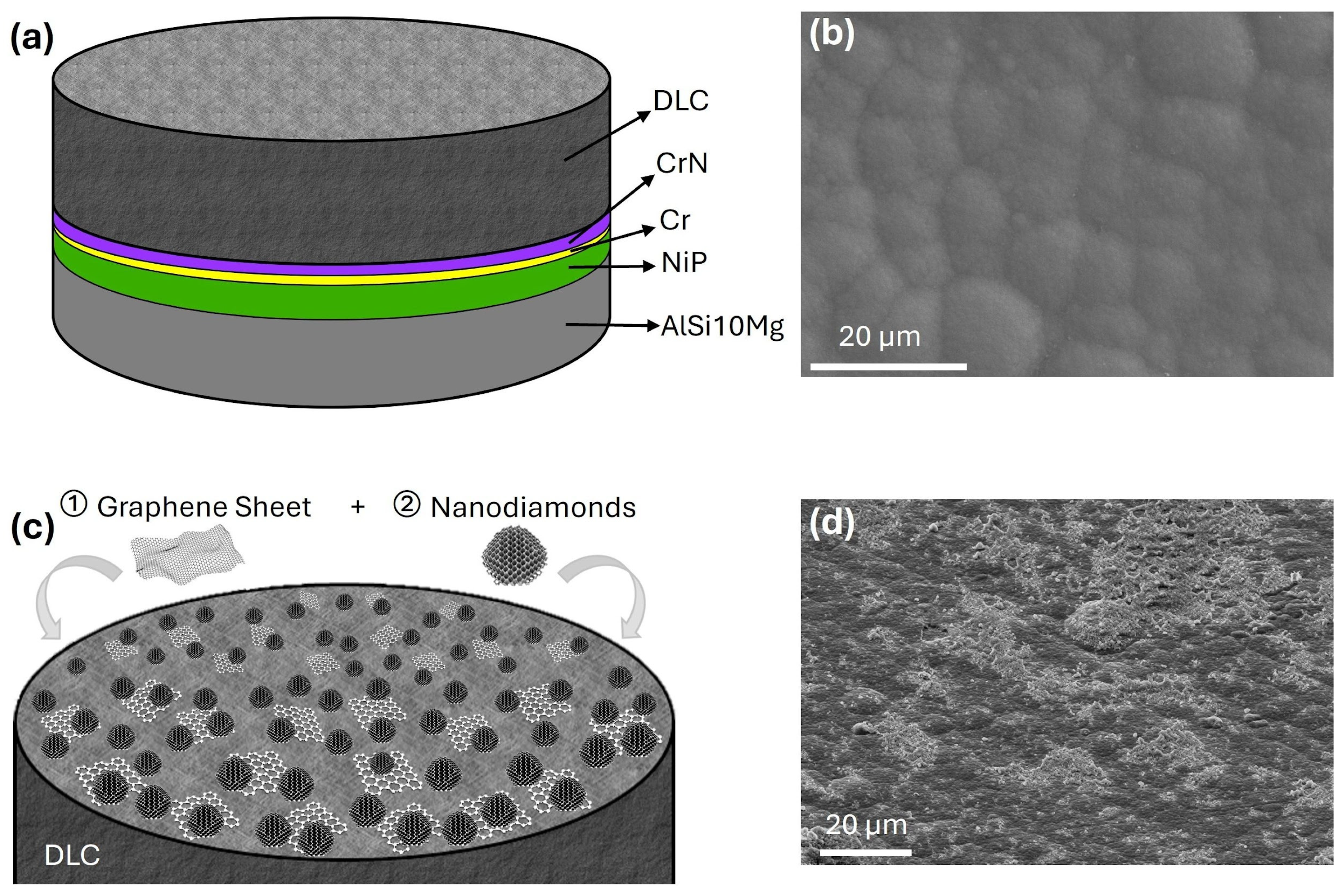
The DLC coatings investigated in this work were manufactured by STS Group S.r.l. (Bologna, Italy) upon specific request. Deposition was carried out on flat, disk-shaped metallic substrates (45 mm in diameter), a geometry commonly adopted for laboratory-scale tribological testing, using industrial-grade processes and a tailored multilayer design. The substrates consisted of aluminum alloy disks (AlSi10Mg), whose surfaces were mechanically ground prior to coating deposition. A sequence of functional interlayers was introduced between the metallic substrate and the DLC film. In particular, a 25 μm thick electroless nickel–phosphorus (NiP) layer was applied to enhance hardness and corrosion resistance, followed by a Cr/CrN interlayer to promote adhesion of the DLC coating. The final DLC layer was deposited by plasma-assisted chemical vapor deposition (PA-CVD) at 250 °C, yielding a hydrogenated amorphous carbon coating with a hydrogen content of 24 ± 8 at.%, characterized by a mixed sp2/sp3 carbon bonding configuration and a nominal thickness of about 2.5 μm. These values identify our coating as belonging to the class of hydrogenated DLCs according to the classification proposed by C.Donnet and A.Erdemir [1]. The overall schematic representation of the multilayer architecture of the DLC coating is shown in Figure 1a.

2.2. Graphene and Nanodiamonds Deposition

Prior to surface functionalization, the DLC-coated disks were ultrasonically cleaned in isopropanol and subsequently treated with oxygen plasma using a plasma cleaner. This treatment rendered the surface hydrophilic, thereby facilitating the spreading of the graphene-based colloidal suspension, which would otherwise localize on limited regions of the DLC surface. Graphene flakes were deposited as the first functionalization step using a commercial ethanol-based suspension (Graphene Supermarket, Graphene Laboratories Inc., Calverton, NY, USA) with a graphene concentration of 1 mg/L. The solution primarily contains single-layer graphene flakes with lateral dimensions of 0.5–2 μm. The GS deposition was accomplished by sequentially dispensing 15 drops (approx. 1 mL total) of the suspension onto the DLC substrate. After each drop deposition, ethanol evaporation was promoted by a gentle N2 flow.
This deposition protocol resulted in a heterogeneous surface morphology, comprising regions covered by single-layer graphene, areas with few-layer flakes (3–4 layers) overlapping, and zones where the underlying DLC surface remained exposed. Such non-uniform coverage is a well-documented characteristic of liquid-phase graphene deposition and has been reported for various graphene sources, deposition strategies, and substrate types.
In the second functionalization step, detonation nanodiamonds (NDs) with particle sizes in the 4–6 nm range (uDiamond® Molto, Carbodeon Ltd., Vantaa, Finland) were deposited onto the graphene-functionalized DLC substrates. The NDs, supplied as an isopropanol suspension, were sonicated prior to use to disrupt agglomerates formed during storage. Owing to their extremely high sp3 carbon content, these nanoparticles exhibit mechanical properties, such as hardness and Young’s modulus, comparable to those of bulk diamond, albeit at the nanoscale. A total of six drops (70 μL each) of the ND suspension (1 mg/mL) were deposited, corresponding to a total deposited mass of 0.420 mg over an area of 15 cm2. Finally, the samples were dried under an N2 stream, promoting both solvent evaporation and uniform nanodiamond dispersion.

2.3. Experimental Techniques

2.3.1. Raman Spectroscopy

The Raman spectra were on a HORIBA LabRAM HR Evolution (HORIBA, Ltd., Kyoto, Japan) and a Jasco NRS-4100 Laser Raman Spectrometer (Jasco International Co., Ltd., Tokyo, Japan). A 100× objective, 600 lines/mm diffraction grating, and a 532 nm laser were used, and the laser power was adjusted in the range 1–3.4 mW. The procedures were optimized to ensure that no visible surface damage occurs and that the spectral shape does not change during the measurements. The data were acquired in the 200–2000 cm−1 range.

2.3.2. Ball-on-Disk Tribometer

Tribological tests of functionalized DLC were performed with a CSM ball-on-disk tribometer (Anton Paar TriTec SA, Corcelles, Switzerland) operated with circular unidirectional sliding, either under humid laboratory air at a relative humidity (RH) of ⋍50–60%, or in a dry N2 environment (RH ⋍ 15%). The relative humidity was monitored using a hygrometer placed inside the tribological chamber. Humid air conditions (50–60% RH) correspond to an ambient laboratory atmosphere, while dry N2 conditions (~15% RH) were obtained by continuously flowing high-purity nitrogen into the chamber. The normal load was applied through fixed masses equivalent to loads between 1 and 10 N. Measurements were conducted at a constant linear velocity (10 mm/s) with a typical sliding distance of 180 m. Average friction coefficients (CoFs) and the corresponding standard deviations were calculated for each test on the stationary part of the curve, typically consisting of the last 100 m. Tests were repeated for each load and for both working conditions on two disks from the same batch, for a total of 24 runs. Stainless SS balls (AISI 440C, G10 grade surface finish by RGPBALLS S.r.l., Milano, Italy) with a root-mean-square surface roughness (Sq) of 0.02 μm and a diameter of 4 mm were adopted as the counterpart, generating a maximum Hertzian contact pressure of ⋍0.8 and 1.6 GPa for the normal loads of 1 and 10 N, respectively. Because the roughness of the DLC coating dominates the contact, the real contact area 〈A〉 is expected to be much smaller than the Hertzian contact area AHertz. As a result, the contact pressure is amplified by a factor~AHertz/〈A〉. Scaling arguments derived from large-scale molecular simulations suggest AHertz/〈A〉~10 − 14 (see [28] for details). Consequently, the contact pressure is likely an order of magnitude higher than the Hertzian pressure, which in turn leads to the pronounced surface wear we observed in the SS balls. We underline that the delamination threshold load of the DLC coating turns out to be greater than the maximum applied load of 10 N, thanks to the interposition of a 25 μm thick NiP interlayer [29]. The specific wear rate of the counterpart (Kball) was calculated as: K b a l l =   V b a l l L l =   π h 2 ( R h 3 ) L l where R is the counterpart ball radius and Vball the ball worn volume, which was assumed to be equal to a spherical cap of height h. The value of h was derived from the circular area of the ball wear scar, measured from optical and SEM images. L and l denote the applied normal load and the sliding distance, respectively.

2.3.3. Optical Profilometry

The morphological characterization of the DLC coating and of the SS balls was carried out both before and after the tribological tests by means of a non-contact Zeta-20 Optical Profiler (Zeta Instruments, Milpitas, CA, USA). Optical micrographs were usually acquired with a 100× objective, with an in-plane optical resolution of about 0.09 μm and a Z resolution of about 0.01 μm. In order to characterize the DLC surface morphology of the tracks with minimum interference from the adsorbed nanomaterials, we gently cleaned a small portion of the disk with a foam-tip cleaning swab soaked in ethanol (Figure S1). The DLC micrographs discussed below were acquired on the cleaned region of the disk. Surface roughness Sq has been estimated as the standard deviation of the height values within the imaged area.

2.3.4. Scanning Electron Microscopy (SEM) and Energy-Dispersive Spectroscopy (EDS) Analysis

Morphological characterization of the functionalized DLC coating and SS balls was carried out using the Scanning Electron Microscope (SEM) Leica Cambridge S360 (Leica Microsystems, Cambridge, England), operated in Secondary Electron (SE) and Back Scattered Electron (BSE) mode, and equipped with the Energy-Dispersive Spectrometer (EDS) Oxford X-Max 20 (Oxford Instruments NanoAnalysis, Bucks, England) for semi-quantitative compositional analysis and elemental mapping. Additionally, we acquired high-resolution SEM and BSE images of worn areas using the Zeiss GEMINISEM 360 (Zeiss Group, Oberkochen, Germany).

3. Results and Discussions

3.1. DLC Film Characterization and Functionalization

The surface morphology of the DLC coatings before and after functionalization was investigated to elucidate changes associated with the deposition of graphene sheets (GSs) and nanodiamonds (NDs). The as-deposited DLC surface exhibits the characteristic microrough, cauliflower-like texture (Figure 1b) commonly observed in industrial multilayer coatings, largely inherited from the underlying electroless NiP interlayer [30,31]. This roughness, while beneficial for mechanical interlocking, poses challenges for the formation of uniform TLs in both dry and humid environments.
Upon functionalization with GSs and NDs, a marked modification of the surface morphology is observed (Figure 1d). SEM images reveal a heterogeneous distribution of nanostructured features superimposed on the native DLC roughness, consistent with the combined presence of graphene-based structures and nanodiamond aggregates introduced through the two-step functionalization process (Figure 1c). Although the surface functionalization leads to a non-uniform distribution of graphene sheets and nanodiamonds, tribological tests in a ball-on-disk configuration ensure that the sliding contact progressively samples a statistically representative surface area. As a result, the effect of local heterogeneities is mitigated during the formation of the transfer layer, leading to reproducible friction behavior.
This composite surface architecture increases the population of nanostructures available at the tribological interface and is expected to influence subsequent sliding behavior. These observations are consistent with previous studies on graphene–nanodiamond-functionalized DLC surfaces [25].

3.2. Load and Environment Dependence of Friction

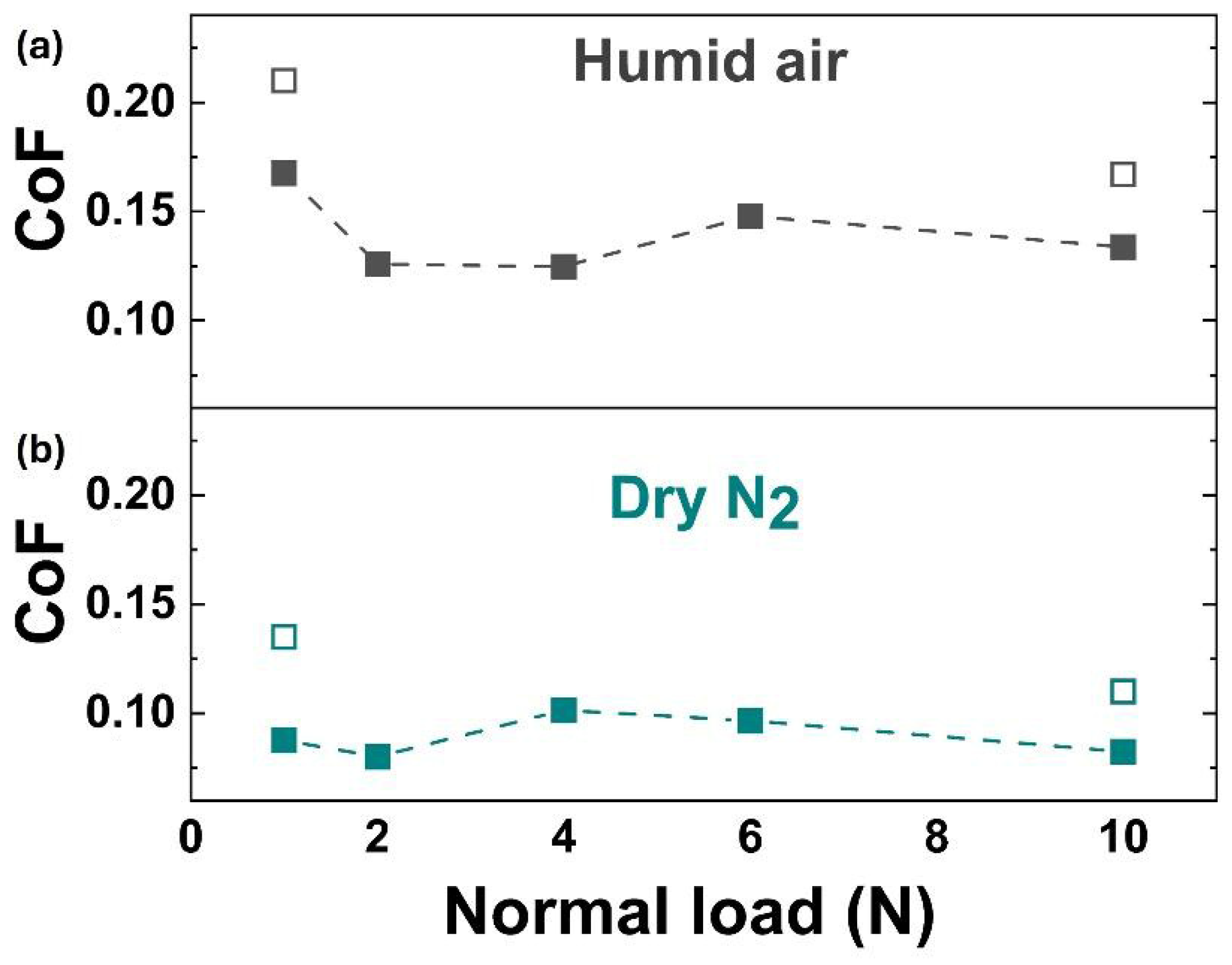
Figure 2 summarizes the CoF variation as a function of the applied load in two different environmental conditions, namely ambient air with relative humidity RH ⋍ 50–60% (for simplicity, named humid air), and in N2 at RH ⋍ 15% (dry N2). The comparison refers to one of the analyzed samples and is representative of the entire set of our results. The CoF values measured on the pristine DLC surface, for 1 N and 10 N, are also shown as a reference. The functionalization consistently reduces the CoF relative to the pristine DLC coating tested under the same conditions. In particular, under dry N2, the CoF remains below the 0.10 threshold, reaching a minimum of about 0.05. In humid air, all CoF values are above the 0.10 threshold, and a comparable load-dependent variation is observed, except for a slightly higher value at 1 N. No clear CoF trend with increasing normal load is observed across the tested range.
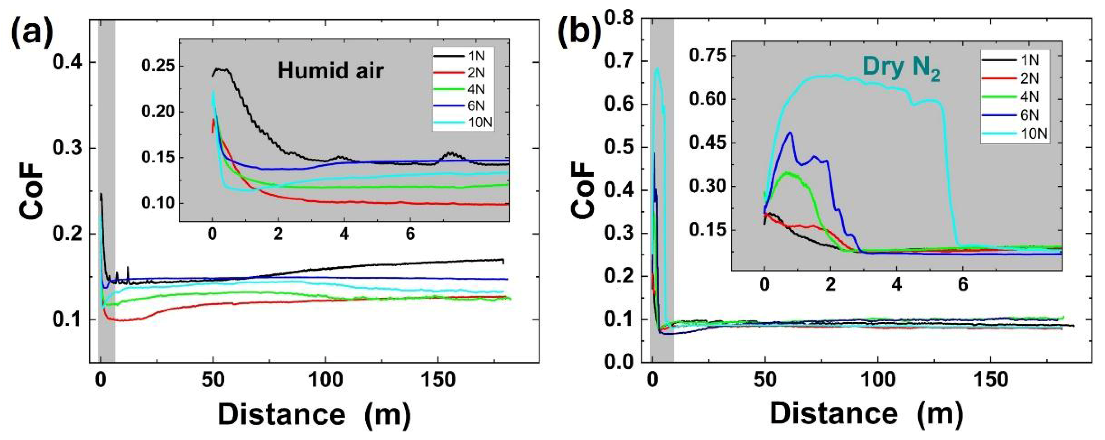
Figure 3 shows the CoF evolution as a function of sliding distance for the normal loads of 1, 2, 4, 6, and 10 N, grouped by working environmental conditions; namely, humid air (Figure 3a) and dry N2 (Figure 3b). The steady-state portion of each curve was used to estimate the average CoF values shown in Figure 2. Beyond steady-state behavior, the initial run-in phase exhibits distinct features that depend strongly on both environment and applied load. At 1 N, the run-in behavior is similar in dry N2 and humid air: in both cases, a rapid and smooth transition from initially high CoF values (⋍0.20–0.25) to a stable lower CoF (⋍0.10–0.15) occurs within the first ⋍2 m of sliding. This behavior indicates the rapid establishment of a TL at the sliding interface. In humid air, comparable run-in behavior is also observed at higher normal loads, with relatively short transient regimes preceding steady-state friction. In contrast, under dry N2 and for loads exceeding 4 N, the run-in phase is characterized by an initial increase in CoF, which persists over progressively longer sliding distances as the load increases. This high-friction transient is followed by an abrupt transition to a low and stable CoF regime. This behavior suggests a load-dependent interfacial adaptation process in dry N2, where an initial phase dominated by abrasive interactions precedes the formation of a lubricious carbonaceous TL that sustains low friction. The implications of this transient behavior for wear and material removal are examined in the following sections through a detailed analysis of the wear tracks on the coating and the wear volumes measured on the SS counterparts.

3.3. Wear Behavior of the DLC Disk

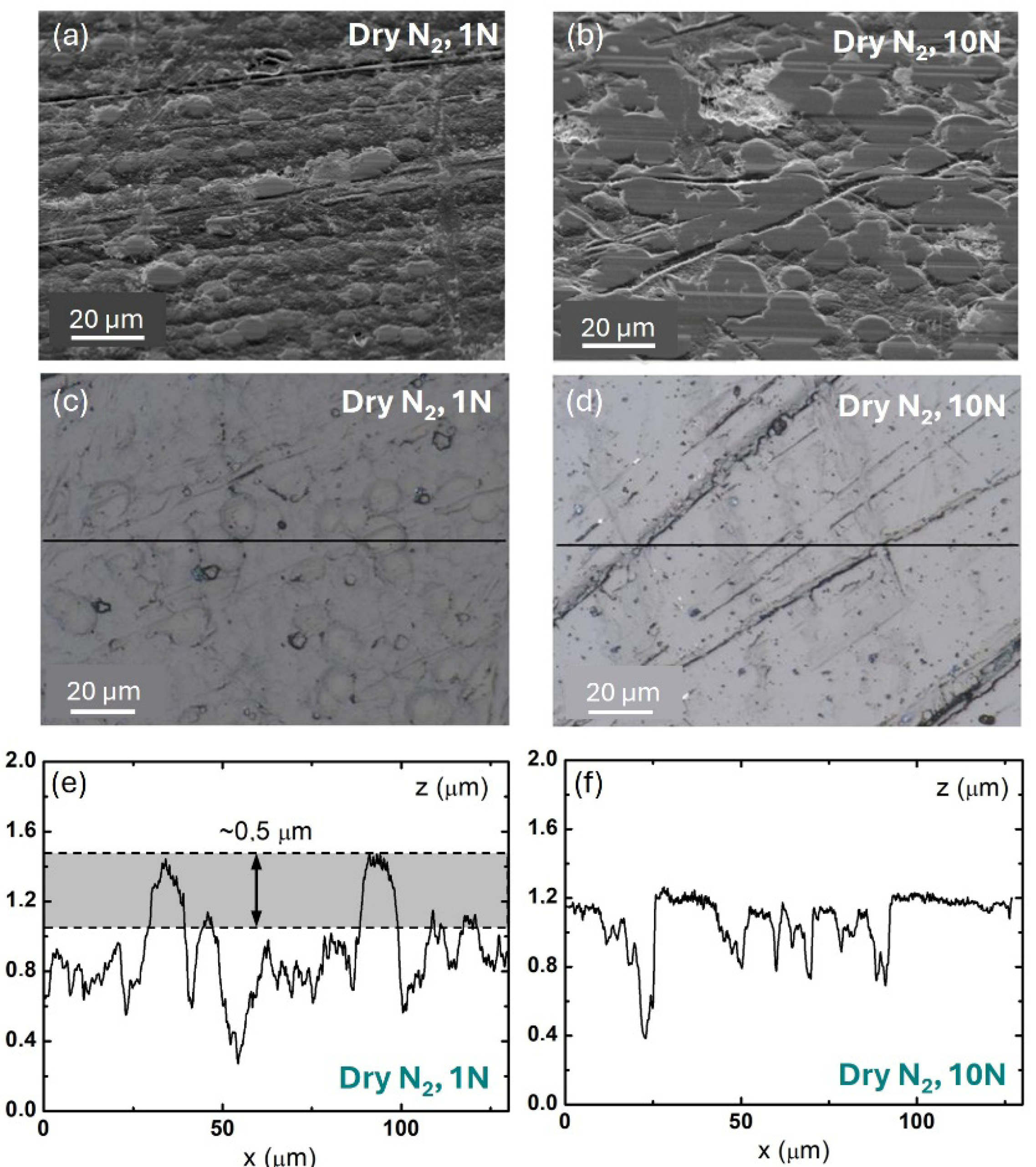
After conducting the tribological tests, we systematically characterized the sliding wear tracks on the DLC disk using optical profilometry and SEM. Figure 4a,b present images of the track formed in dry N2 at a 1 N load, indicating that DLC wear was primarily localized at the highest protrusions, which appear truncated. This indicates a marked evolution of DLC morphology within the sliding tracks relative to the surrounding regions, with surface wear particularly pronounced in the agglomerate structures that contribute to the long-scale roughness. The flattening of these protrusions increased with normal load, leading to extended flattened areas at the maximum load of 10 N, as shown in Figure 4c,d. Height profile analysis (Figure 4e,f) reveals that the protrusion flattening reached roughly half a micron at 10 N.
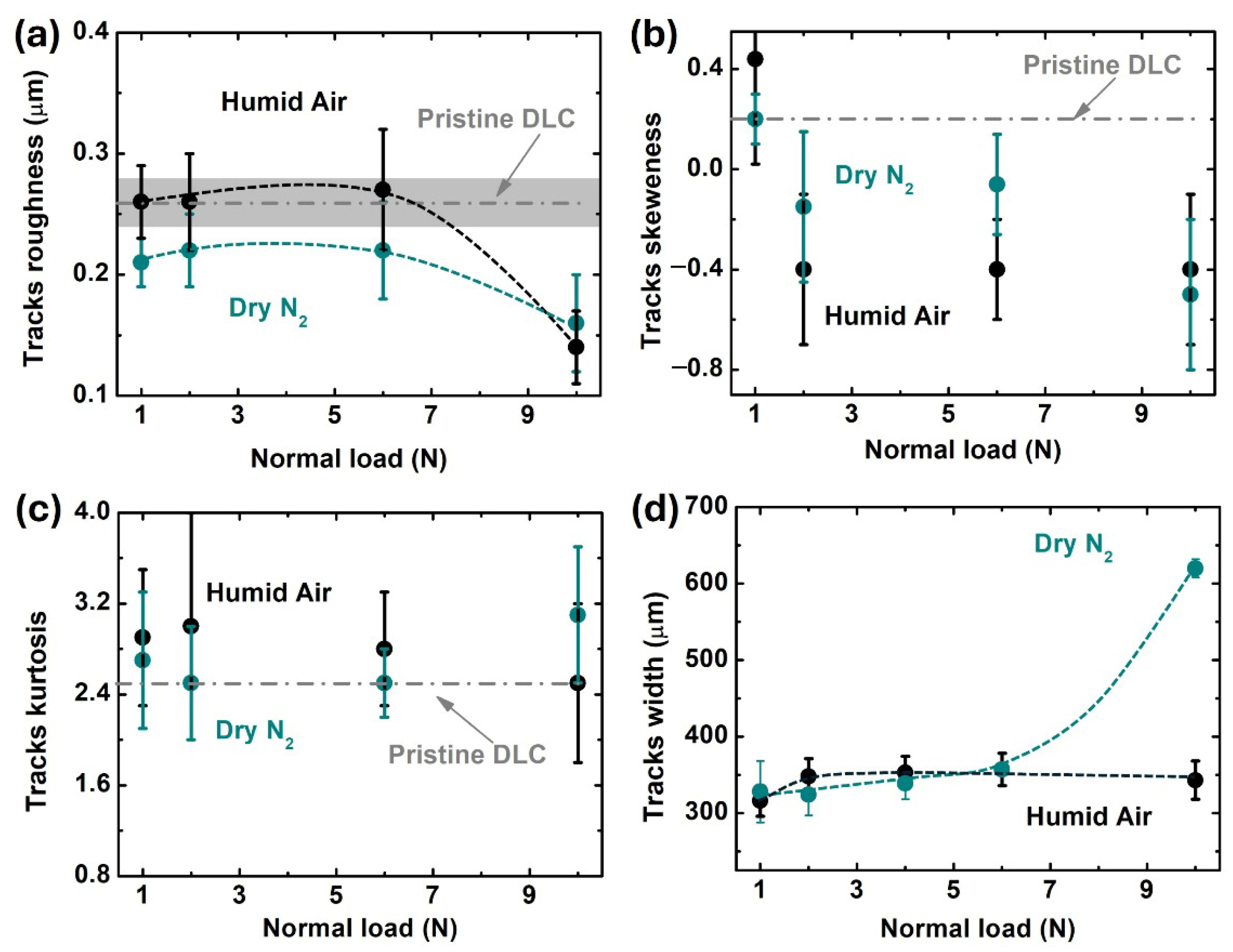
Although this wear effect translates into a measurable change in roughness as a function of load, the overall volume removed was difficult to quantify due to the inherently high roughness of the pristine DLC surface. The surface roughness was therefore selected as a first qualitative parameter to track the evolution of wear on the disk. As shown in Figure 5a, the trend is similar in both humid air and dry N2. Up to a load of 6 N, the Sq values remain nearly constant and are lower in dry N2 compared to humid air. Also, up to a load of 6 N, the Sq values in humid air are similar to those of the pristine DLC coating, which has Sq = 0.26 ± 0.03 μm. At the maximum load of 10 N, however, both environments lead to a sizable decrease in the tracks’ roughness to approx. Sq = 0.15 μm, suggesting the possible onset of a new abrasive mechanism. Consistent with the flattening of the DLC protrusions described above, the estimated skewness Ssk decreased monotonically with increasing load. This trend—shown in Figure 5b and contrasted with the skewness of pristine DLC (Ssk∼0.2)—was again similar in both humid air and dry N2. The inversion of the Ssk sign above a 1 N load clearly captures the morphological transition of the DLC surface, from one dominated by sharp protrusions (Ssk > 0, Figure 4e) to a topography characterized by broad plateaus interrupted by deep valleys (Ssk < 0, Figure 4f). In contrast, the surface kurtosis (Sku), reported in Figure 5c, reveals a somewhat different evolution of the surface sharpness in humid air compared with dry N2. In dry N2, Sku increases markedly at a 10 N load, which we attribute to the formation of scratches within the wear tracks (Figure 4d), due to the longer run-in period (Figure 3b) and more severe abrasive wear. Conversely, in humid air, Sku decreases with load up to 10 N, as expected when surface peaks are progressively worn down and leveled. Another relevant parameter reflecting wear effects is the normal load dependence of the track width. Track widths for each normal load tested were estimated using SEM BSE images (Figure S2) and summarized in Figure 5d. In humid air, the track width was nearly load-independent and centered at approximately 350 μm up to 10 N. In dry N2 conditions, the behavior was similar up to 6 N; however, at the highest load of 10 N, a twofold increase in width was observed.
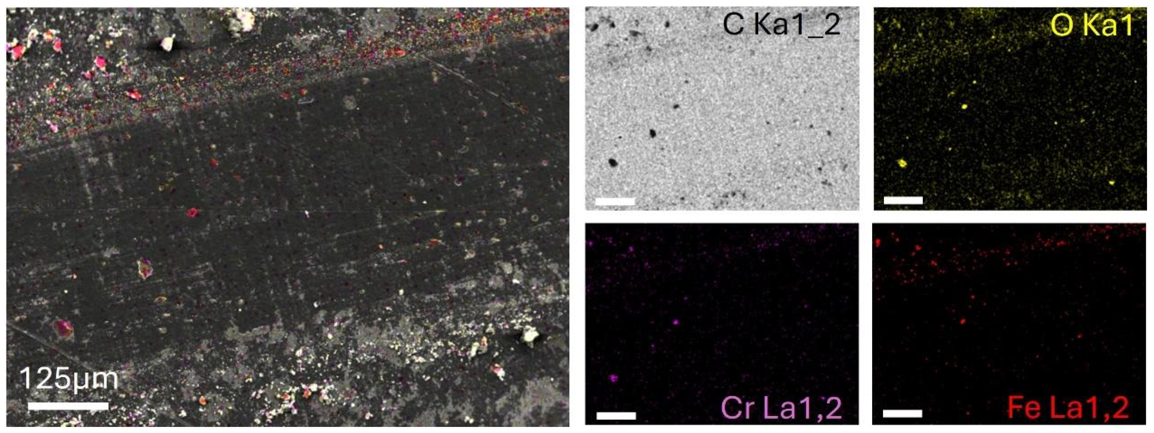
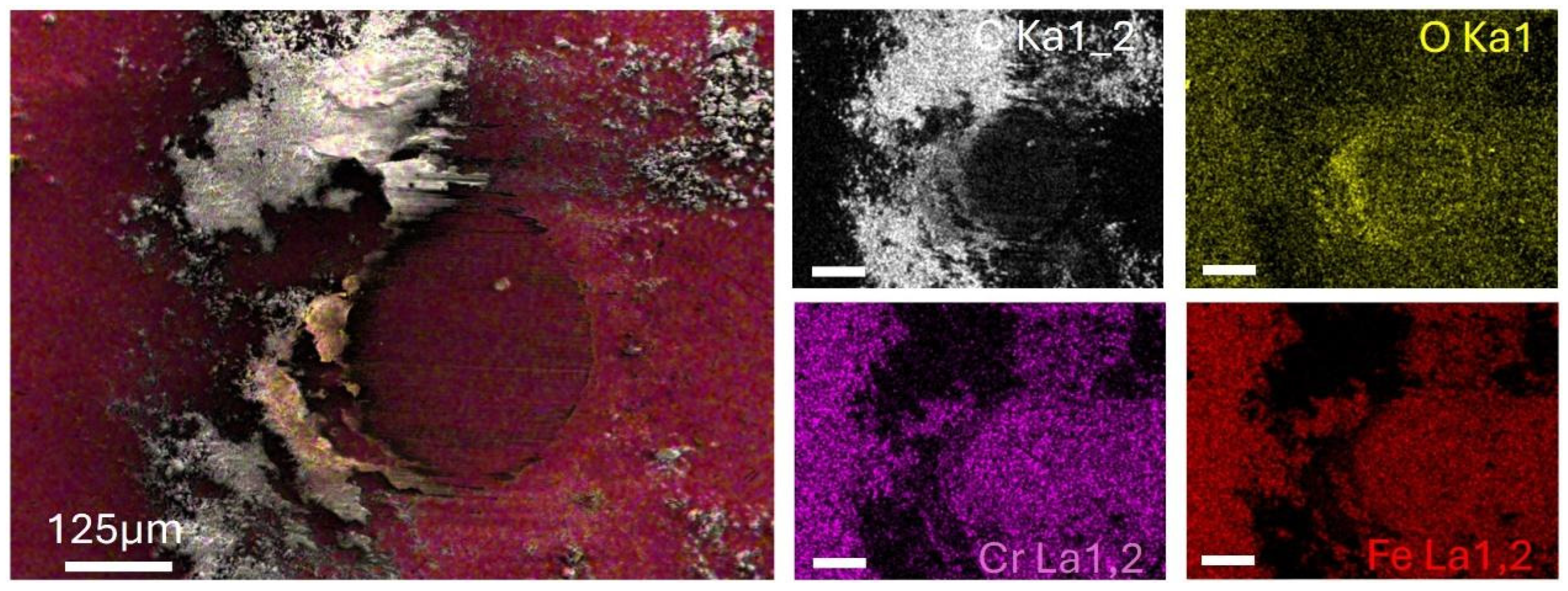
In addition to the flattening of the DLC protrusions, SEM-EDS analysis revealed the accumulation of debris particles from the SS ball, both alongside the flattened regions [25] and at the edges of the wear tracks. This can be inferred from Figure 6, where the localization of C, Fe, Cr, and O signals is highlighted (see Figure S3 for additional SEM-EDS analysis of the DLC sliding tracks at 10 N, respectively in dry N2 and humid air).

3.4. SS Ball Counterface Analysis

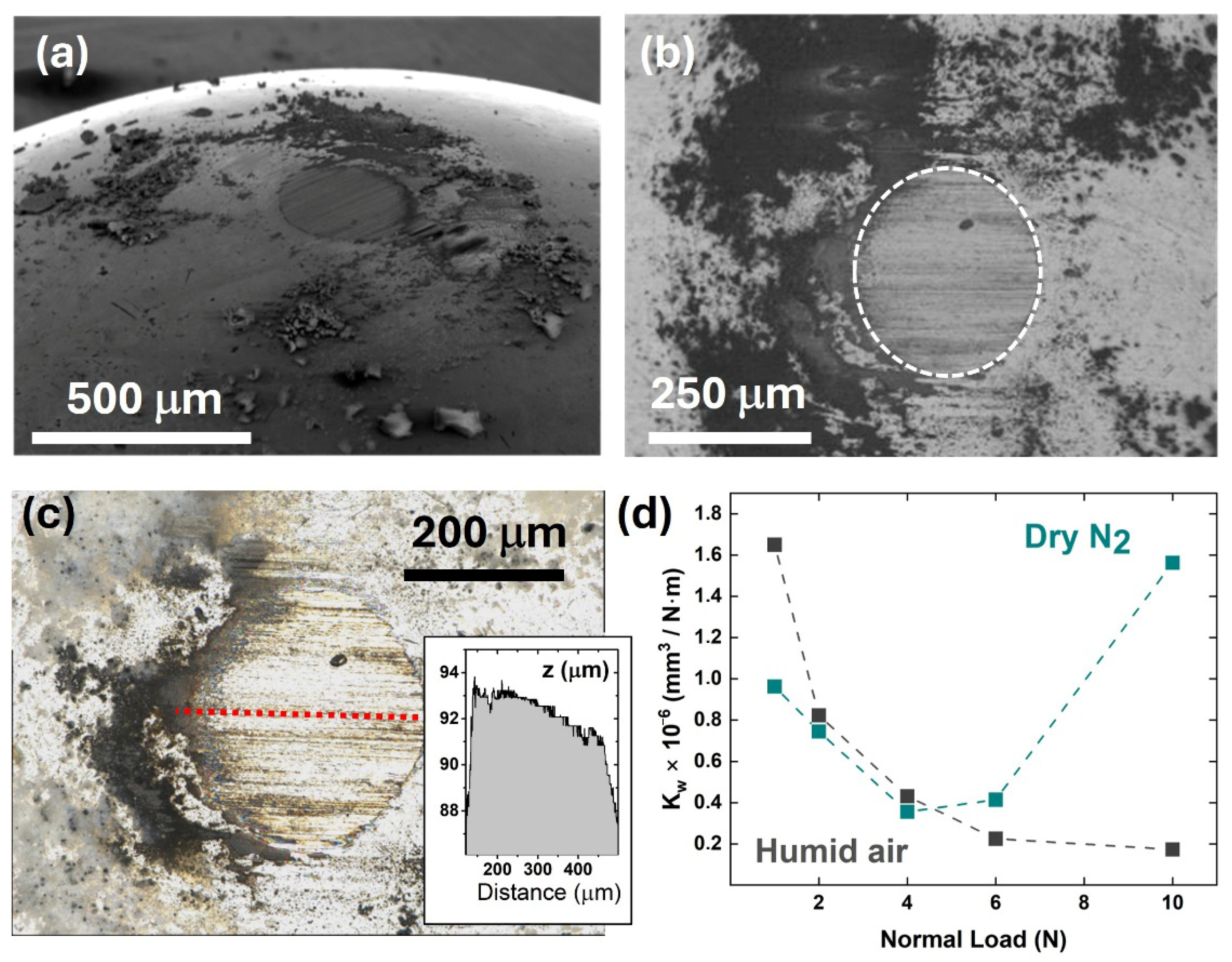
Large wear effects, leading to a measurable volume erosion, were noticed on the SS balls counterfaces. In both humid air and dry N2, the sliding of the balls against the functionalized DLC created a circular wear scar surrounded by loose debris particles (Figure 7a,b), indicating a circular contact region. In dry N2, the wear scar area progressively enlarged from 5 × 104 μm2 at 1 N to 5 × 105 μm2 at 10 N, while in humid air, a constant area of about 0.8–1.0 × 105 μm2 was observed regardless of the applied load. The roughness within these areas, as measured by optical profilometry, was typically in the range of 80–100 nm (e.g., see Figure 7c). This finding aligns with the load dependence of the sliding track widths summarized in Figure 5b but does not conform to a simple Hertzian deformation law, which would predict a load-dependent increase with a 2/3 power and much smaller contact areas (2–9 × 103 μm2).
From the estimated value of the circular contact area (Aball), we evaluated the wear rate (Kw) according to the formula presented on Par. 2.3.2. Wear on the SS balls’ counterface appears significantly dependent on environmental conditions (Figure 7). In humid air, the wear rate decreases monotonically with load. In dry N2, up to a 4 N load, the wear rates are lower than in humid air but increase dramatically at 10 N, reaching a 3–4-fold increase. This is directly related to the evolution of the run-in period shown in Figure 3, whose duration increases from ~3 m in the 1 N–6 N range to ~6 m at 10 N. In the latter case, besides the pronounced flattening of the DLC protrusions (Figure 4e,f), deeper surface scratches and occasional local coating spallation are observed (e.g., see Figure 4b,d). Taken together, these findings point to a load-triggered amplification of abrasive wear at 10 N. This accelerated wear likely reflects a transition toward third-body abrasion, associated with the generation of larger debris particles and/or a stronger abrasive action from the interfacially trapped NDs. We cannot fully exclude that, at 10 N, a local breakdown of the DLC passivation might also lead to the formation of reactive carbon sites and possible Fe–C bonding, thereby triggering adhesive wear effects.
An investigation of the wear scar by EDS elemental analysis was carried out under dry N2 (Figure S4) and humid air (Figure S5) at normal loads of 1, 2, 6, and 10 N. A detailed EDS elemental distribution of C, O, Fe and Cr for the case of a dry N2 atmosphere and a 1 N load is presented in Figure 8. The results indicate that the debris is mainly composed of carbonaceous species, while the wear scar spectrum is dominated by the Fe signal. Under dry N2 sliding conditions, the oxygen signal does not show a significant increase compared to the unworn SS ball surface (Figure S6), suggesting that tribo-induced oxide formation within the contact region is minimal. Notably, the oxygen signal is confined to the leading edge of the contact; this localization is consistent with mild oxidative wear processes. In contrast, the carbon signal is widespread across the surface; this distribution indicates the formation and redistribution of the TL on the ball surface.
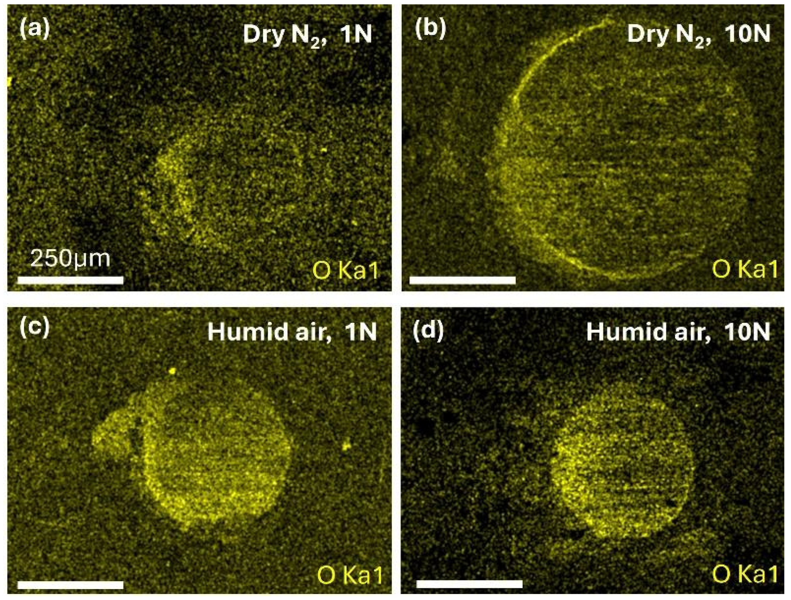
In contrast, when sliding in humid air, both the SS surface and the TL reacted with the ambient oxygen. This is evidenced by a prominent and spatially uniform distribution of oxygen across the circular wear scar and within the (carbonaceous) debris particles contained within it. The situation is summarized in Figure 9, which presents EDS maps of oxygen distribution after SS balls were slid against functionalized DLC under dry N2 and humid air conditions for two extremes of the tested normal load range (1 N and 10 N). The maps reveal a markedly higher oxygen signal under humid air conditions at both loads, indicating enhanced tribo-oxidative processes at the ball–coating interface. In contrast, tests performed in dry N2 show a strongly reduced and spatially confined oxygen signal, even at 10 N, consistent with mild oxidation and the stabilization of the carbonaceous TL under an inert atmosphere.
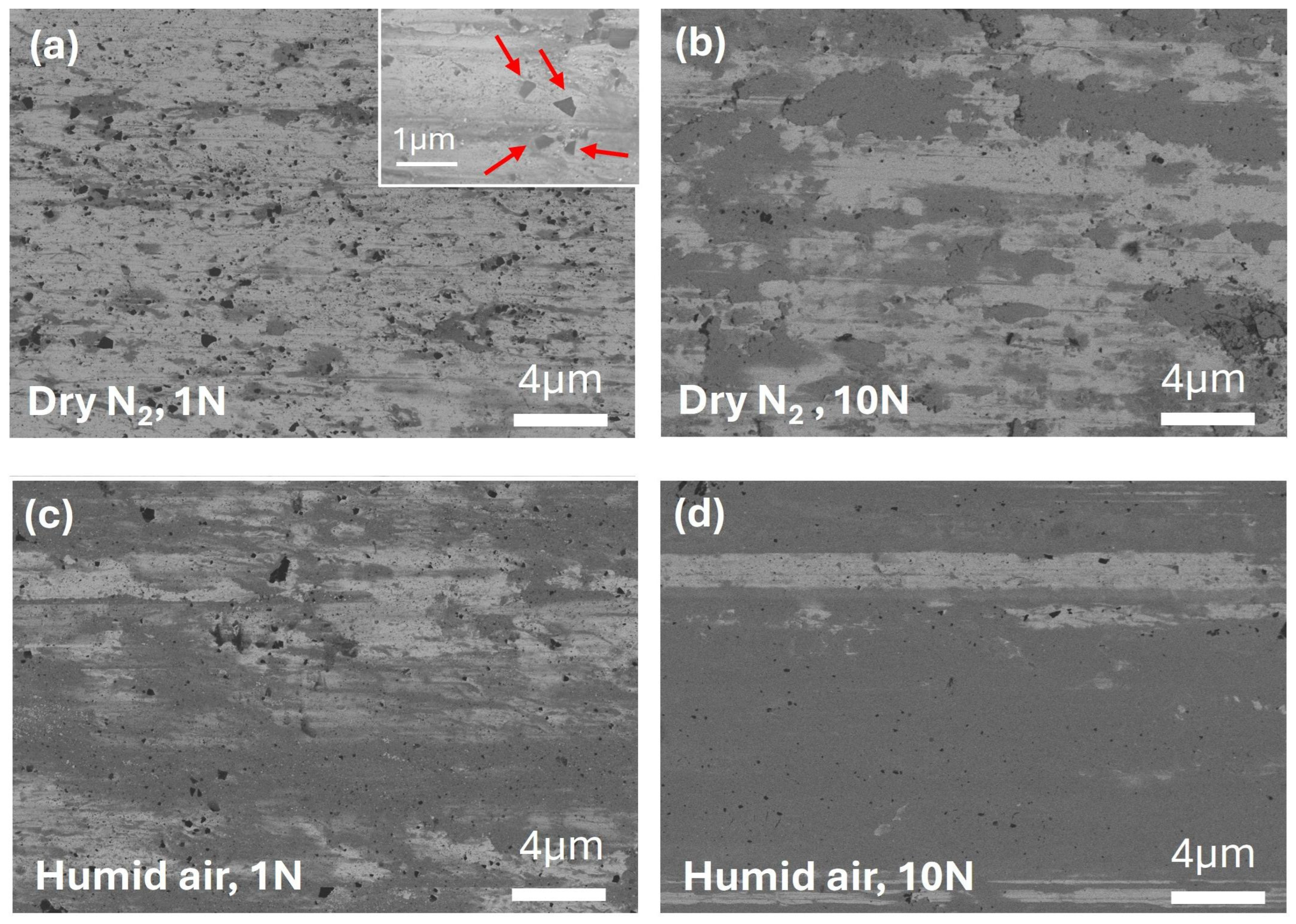
Figure 10 further highlights compositional differences among the SS wear scars formed in humid air and dry N2 conditions, using BSE imaging with an energy filter to enhance surface sensitivity. In dry N2 at 1 N, GSs contributing to the TL formation appear as nanosized faceted black spots uniformly distributed over a light-gray background containing discontinuous dark-gray patches (Figure 10a), attributed to localized surface oxides. Increasing the normal load to 10 N (Figure 10b) reduces the population of GSs (though they remain appreciable across the examined area) and leads to a corresponding increase in surface oxides, consistent with the mild evolution of the oxygen maps obtained by EDS analysis (Figure 9a,b, Figures S3 and S5).
It was previously shown [25] that in dry N2, the TL consists of a distribution of sub-micrometric deposits arranged into sliding-induced surface striations. We ascribe the origin of the ultralow CoF of functionalized DLC to the distinctive nature of this TL within the contact region. It forms during the run-in phase through a process driven by the competition between interfacial erosion and the development of a transfer film involving DLC, GSs, and NDs, until a stable contact is established. As extensively discussed [25], CoF reduction occurs only in the simultaneous presence of both carbonaceous nanostructures (NDs and GSs), resulting from GS milling by NDs and their incorporation into the lubricious TL distributed across the contact region. This picture is supported by detailed microscopic and spectroscopic analysis of the TL at a 1 N load in dry N2 [25]. By contrast, in humid air, BSE micrographs reveal fewer features associated with carbonaceous species, superimposed over an extended dark-gray background that reflects the increase in surface oxide coverage (Figure 10c,d).
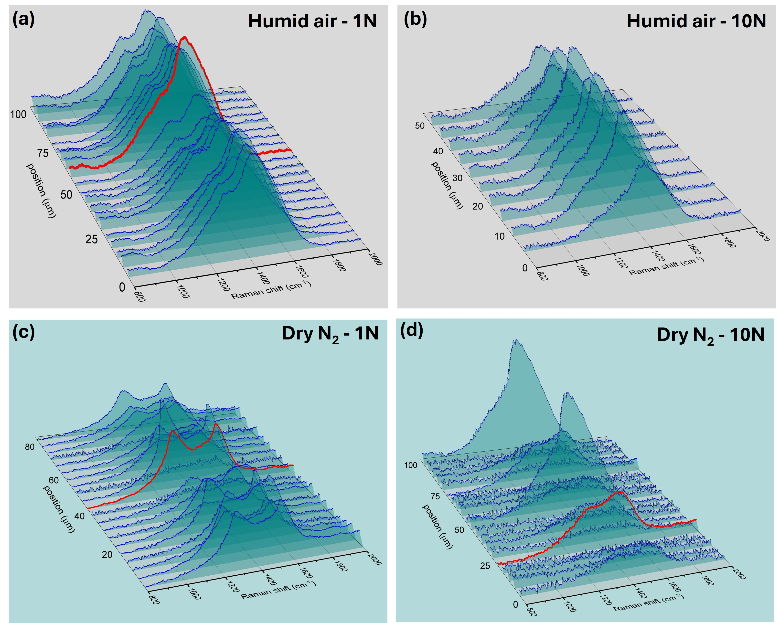
To gain deeper insight into the nature of the TL formed under different sliding conditions, Raman spectroscopy was employed. Owing to the intrinsically non-uniform structure of the TL and, conversely, to the micrometer-scale size of the laser spot in surface Raman spectroscopy, Raman line-scan maps were acquired. Each map consists of approximately twenty acquisition points evenly distributed along a line crossing the wear scar, corresponding to a set of Raman spectra collected from areas spaced by a few micrometers.
Figure 11 reports representative three-dimensional Raman line-scan maps of TLs formed on SS balls slid against functionalized DLC under humid air and dry N2 atmospheres, at applied normal loads of 1 N and 10 N. Under humid air conditions (Figure 11a,b), the Raman signal appears relatively uniform along the scanned region at both loads, indicating the formation of compact and spatially homogeneous TLs. The overall Raman intensity remains significant even at 10 N, although a progressive simplification of the spectral line shape is observed with increasing load.
In contrast, under dry N2 conditions (Figure 11c,d), the Raman response exhibits a markedly heterogeneous spatial distribution. At 1 N, the TL is characterized by a strong and structured Raman signal over a large fraction of the scanned area, whereas at 10 N, the signal becomes confined to limited regions and varies strongly in intensity over micrometric distances. This spatial heterogeneity is consistent with the pronounced increase in wear and contact area observed at high load, indicating partial mechanical disruption of the TL.
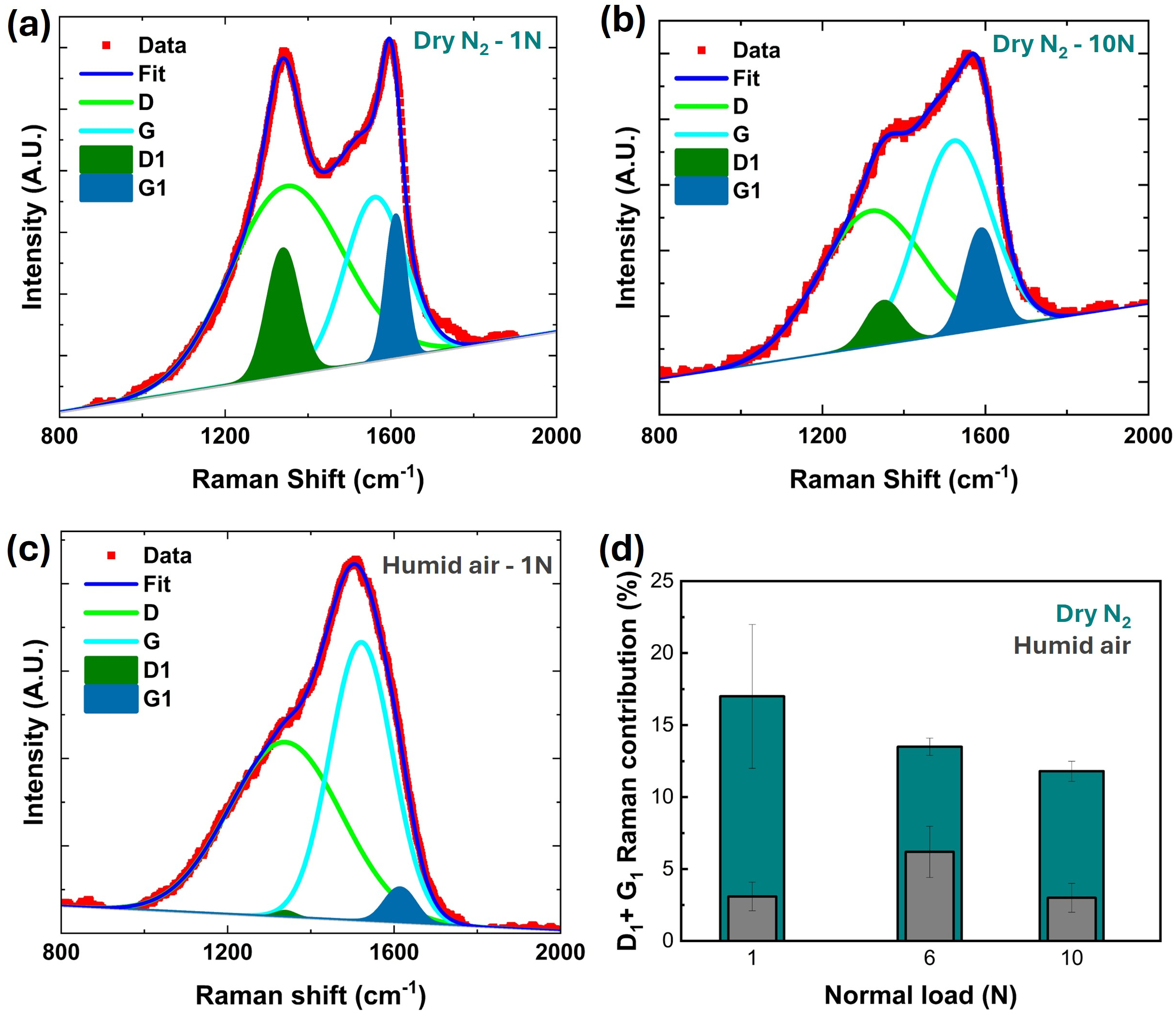
To further elucidate the nature of the carbonaceous phases forming the TLs under different conditions, representative Raman spectra were deconvoluted into multiple components, as shown in Figure 12. The Raman line shape can be described by four contributions arranged in two double-peak systems, which allow different carbonaceous species within the TL to be distinguished [25,28,32,33,34,35,36].
In brief, the first doublet, centered at approximately 1340 and 1540 cm−1, corresponds to the D and G bands of amorphous carbon, associated with DLC wear debris and graphitic carbon. The second doublet, located at about 1335 and 1600 cm−1, is attributed to a distinct nanostructured carbon phase containing nanodiamond cores surrounded by graphitic layers and/or functional groups. The amorphous carbon contributions appear as broad features, while the nanodiamond-related components (denoted as D1 and G1) are sharper and more localized (see details in the Supplementary Materials, Figure S7).
At increasing load, a gradual reduction in the nanostructure-related features is observed, particularly under humid air conditions at 10 N, where the Raman response becomes dominated by the D and G bands of amorphous carbon. In contrast, under dry N2 at 10 N, weak but discernible D1–G1 features are still detected in localized regions, indicating that nanostructured carbon species are not completely suppressed, although their reduced intensity and altered spectral profile suggest a lower degree of structural ordering compared to the low-load case. The relative contribution of nanodiamond-related structures to the overall TL composition, quantified through the ratio of their Raman peaks areas with respect to the total area, is summarized in Figure 12d.

3.5. Friction Mechanisms

The experimental results discussed above indicate that the frictional response of GS–ND-functionalized DLC coatings is governed by the load- and environment-dependent formation, stability, and composition of carbon-based TLs at the sliding interface. Rather than being dictated by friction values alone, the observed behavior reflects the interplay between mechanical stress, wear evolution, and the chemical–structural nature of the interfacial carbon phase. The following discussion rationalizes the observed trends by separately addressing the GS–ND lubrication mechanisms active in dry N2 and humid air. Note that control experiments by different groups [21,25] have already demonstrated that using only GS or NDs is not as effective as the two-step functionalization procedure.
In a dry N2 environment, Berman et al. [21] reported stable superlubricity against smooth SiO2 substrates for normal loads between 0.5 and 3 N. In our study, which involves a rough DLC coating, we demonstrate that lubrication by GSs and NDs remains effective up to a normal load of 10 N. This is evidenced by all CoF values for the tested normal loads being notably lower than those recorded for the pristine SS–DLC tribocouple, with a stable CoF below 0.1 and a minimum value of approximately 0.05 under dry N2. As the normal load increases, mechanical abrasive wear becomes more pronounced on both the coating and counterpart surfaces (see Figure 4, Figure 5, Figure 7d and Figure 9a,b). At a 10 N load, we report a delay in the formation of a stable lubricious TL, as high contact stresses and an increased debris removal rate very likely interfere with the nucleation and growth of the main carbon components, namely the amorphous carbon network and the self-assembled nanoscroll-like features, which together constitute the TL [28]. In particular, the self-assembly of nanostructures may be hindered at higher contact stresses due to the squeeze-out of NDs and GSs from the contact zone, and/or excessive fragmentation of GSs induced by NDs (see Figure 10a and related discussion). In line with this interpretation, at higher normal loads, an increase in the TLs’ spatial inhomogeneity has been measured through counterface Raman analysis (see Figure 11c,d). More importantly, however, the TLs consistently exhibit abundant D1 and G1 fingerprints indicative of nanoscroll-type structures (Figure 12a,b,d). This persistence confirms that ND-related nanostructures remain embedded within the TLs even under the highest loads, and they continue to play a crucial role in sustaining the lubrication effect in dry N2 despite intensified wear. As discussed in our previous studies [25,28], the synergistic interaction between GSs and NDs is supported by both control experiments and direct microscopic evidence. High-resolution SEM [ as well as ADF-STEM and HRTEM analyses [28] consistently demonstrated the formation of a TL with a thickness of several hundred nanometers, within which different types of nanostructures are effectively incorporated. As noted above, the observation of GSs with lateral dimensions significantly smaller than expected (Figure 10) supports the hypothesis that GSs undergo milling by NDs and are subsequently incorporated into the lubricious TL, mainly within core–shell nanostructures. Although the formation of such nanostructures appears to be a general mechanism reported across a wide range of tribocontacts lubricated by various nanomaterials [18,21,22,23], in the specific case of a rough DLC/SS tribocontact, we obtained direct evidence through high-resolution SEM micrographs collected within the wear tracks of functionalized DLC after sliding tests in dry N2 [25]. These images revealed linear, nanoscroll-like features, likely originating from the sliding-induced self-assembly of NDs and GSs.
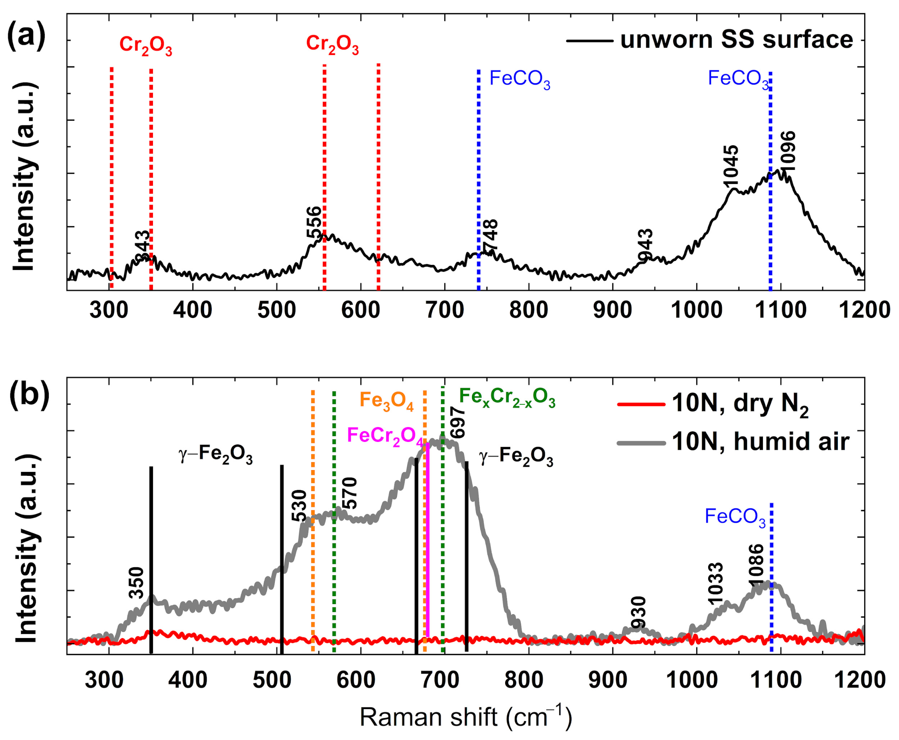
Conversely, in humid air, oxidative wear dominates across all normal load conditions. SEM-EDS analysis (Figure 9c,d and Figure S5) reveals that oxygen is strongly localized and prominent throughout the circular wear scar, overlapping both Fe/Cr signals from the ball surface and the C signal from the carbon-based debris within the wear scar. Notably, no O signal is detected on the thick carbon debris outside the contact area, indicating that oxidation takes place under the combined effects of contact pressure and sliding friction [37]. EDS quantification of the elemental atomic ratios within the wear scars (Figure S6) indicates that oxygen accounts for 14.18–18.93 at.%, which is at least three times higher than in dry N2 conditions (1.40–4.68 at.% O). The SS oxidation can be further characterized by Raman spectroscopy. Raman spectra of the unworn SS surface (Figure 13a) exhibit two weak, broad bands at 343 and 556   cm 1 , consistent with contributions from chromium oxide Cr2O3 (reported bands 305, 350, 551–561, and 609–623 cm 1 ) [38,39,40]. Features above 700   cm 1 can instead be attributed to ubiquitous ‘carbonate-like’ surface species [41]. Under friction in dry N2 at 10 N, the Raman spectra collected on the wear scar (Figure 13b) show no distinct features below 1200   cm 1 , indicating that the native surface oxides are removed during run-in and do not reform during the test. In contrast, friction at 10 N in humid air leads to the appearance of two broad bands at 555 and 699 cm−1, indicative of a mixture of iron and chromium oxides. These likely include chromite (FeCr2O4 main peak at 674 cm−1 [42]), Fe-substituted chromium oxide (FexCr2−xO3; peaks at 560 and 698 cm−1 [38]), maghemite (γ-Fe2O3; peaks at 660–670 and 700–730 cm−1 [41,43,44]), and magnetite (Fe3O4; peak at 670 cm−1 [45]). We note that the formation of FeCr2O4 in SS/DLC tribocontacts under oxidizing atmospheres has been reported previously [46], and Fe3O4 formation was documented as a tribochemical product at SS/DLC interfaces tested under moderate RH (⋍40%, [45]). A key consequence of developing such protective oxide layers is that ball surface hardening almost levels off abrasive wear with respect to the applied load (Figure 7d) [47]. As a result, the contact area remains nearly constant at a diameter of about 350 μm (Figure 5b). This is in stark contrast to the load-dependent scaling observed in dry N2 for the contact area. Recent TEM-EELS results [28] in turn provide deeper insight into the nature of carbon-based nanostructures forming the TLs in humid air. Analysis of the C-K edge estimates a relative sp2 content of 65%, including contributions from graphitic shells and a-C. The O/C ratio is approximately 0.10, with a predominance of C=O groups, suggesting that oxidation primarily affects the amorphous carbon regions. Raman analysis (Figure 12c) further confirms that, in humid air, the amorphous carbon network represents the main component of the TLs. On one hand, the lower degree of structural order and spatial continuity of sp2 domains in ambient air, compared to N2, accounts for the reduced lubricity observed between the two environments. On the other hand, the presence of oxygen-containing functional groups within the TL likely promotes stabilization and enhances boundary lubrication through physisorbed water molecules supplied by the gas phase. This mechanism is consistent with known lubrication behavior [45], wherein physisorbed water yields CoFs in the range of 0.10–0.15. Indeed, these reported values align closely with our measurements (Figure 2). Therefore, although less effective than in dry conditions, GSs + NDs functionalization still provides mild lubrication compared to the pristine SS–DLC contact.

4. Conclusions

In this work, the load- and environment-dependent friction mechanisms of a realistic microrough SS/DLC contact functionalized with graphene sheets and nanodiamonds have been systematically investigated. By combining tribological testing with detailed morphological, chemical, and spectroscopic analyses, the evolution of friction, wear, and transfer-layer structure was elucidated over a wide range of normal loads (1–10 N) in dry N2 and humid air.
The main findings of this study can be summarized as follows:
In dry N2, the synergistic action of GSs and NDs enables a robust low-friction regime, with the CoF remaining below 0.10 across the entire investigated load range. Increasing the normal load leads to a pronounced increase in wear and real contact area; however, this is not accompanied by a corresponding increase in friction, highlighting the key role of nanostructured carbon transfer layers.
The persistence of low friction under increasing load suggests that such nanostructured TLs can sustain low shear strength even under severe mechanical conditions, despite intensified abrasive wear.
In humid air, the tribological response is governed by oxidation processes affecting both the TL and the wear debris. The formation of oxide-rich TLs and the predominance of amorphous carbon result in higher friction levels that are largely insensitive to the applied normal load.
Although less effective than in dry N2, GS–ND functionalization still provides a measurable reduction in friction compared to pristine SS/DLC contacts, likely assisted by oxygen functionalization and physisorbed water molecules promoting boundary lubrication.
Overall, these results demonstrate that GS–ND-based functionalization strategies can deliver load-resilient low-friction behavior in microrough metal/DLC systems under inert environments, while highlighting the critical role of environmental chemistry in limiting lubrication performance in ambient air. The present findings provide design guidelines for assessing the robustness and operating limits of nanostructured carbon lubricants in realistic tribological applications.

Supplementary Materials

The following supporting information can be downloaded at: https://www.mdpi.com/article/10.3390/lubricants14050184/s1, Figure S1 Optical image of the functionalized DLC disk after the tribological tests. The concentric circles indicate the positions of the sliding tracks. The red dashed box outlines the area cleaned with an ethanol-soaked swab to remove the adsorbed nanomaterials, thus facilitating the reliable profilometric characterization of track morphology. The table details the lateral position, load and working environment of each sliding track; Figure S2. SEM images of 11 sliding tracks on the functionalized DLC disk are shown in: (a, c, e) SE mode and (b, d, f) BSE mode. We estimated the effective width of each track from the BSE images (red arrows outline the width of representative tracks, measured about 20 times to provide one averaged data point in Figure 5b), as they were less affected by the functionalized surface. The lateral position, load and working environment for each sliding track are the same as in Figure S1; Figure S3. SEM-EDS analysis of a GS–ND-functionalized DLC surface after sliding against an SS counterpart at the maximum applied load of 10 N. The left panels show SEM images of the tested regions crossed by the wear tracks, and overlaid with the elemental signals; Figure S4. EDS maps of the wear scar on the SS balls probed in dry N2, for increasing normal loads In the first column, a progressive increase in the contact area with the normal load is observed. In the third column, there is evidence of mild oxidative processes at the front edge; Figure S5. EDS maps of the wear scan on the SS balls probed in humid air, for increasing normal loads. In the first column from the left, one can see that the contact size does not evolve with the normal load. In the third column, evidence of oxidative processes is observed across the entire contact area; Figure S6. EDS elemental analysis of the wear scars shows how surface oxidation evolves with normal load and working environment. In dry N2, oxidation remains mild and is restricted to the leading edge of the contact (Figure S4), whereas in humid air it increases by approximately one order of magnitude and spreads across the entire contact area (Figure S5). The composition measured on the unworn SS surface is consistent with the nominal AISI 440C values provided by the manufacturer. Figure S7. Evolution of the Raman spectra contributions as a function of load in different environment; (a) peak positions in humid air; (b) ID/IG ratio in humid air; (c) peak positions in dry N2; (d) ID/IG ratio in dry N2

Author Contributions

A.M.: Formal analysis, Investigation, Data curation, Conceptualization, Original draft, Validation, Writing, Review and Editing. F.Z.: Formal analysis, Investigation, A.R.: Investigation, Validation. C.B.: Resources, Investigation. A.G.: Resources, Investigation. R.C.: Resources, Investigation. L.R.: Resources, Investigation. M.B.: Resources, Investigation, Review and Editing. S.G.: Resources, Investigation, Review and Editing. R.B.: Project administration, Funding acquisition, Original draft, Validation, Writing, Review and Editing. G.P.: Project administration, Funding acquisition, Original draft, Validation, Writing, Review and Editing. All authors have read and agreed to the published version of the manuscript.

Funding

This work was funded by the project PRIN UTFROM Grant No. 20178PZCB5 founded by the Italian Ministry of University and Research, and ECOSISTER project funded under the National Recovery and Resilience Plan (NRRP), Mission 4 Component 2 Investment 1.5—Call for tender No. 3277 of 30 December 2021 of Italian Ministry of University and Research funded by the European Union—NextGenerationEU; Award No. 0001052 of 23 June 2022. S.G. and M.B. acknowledge support from Research Ireland (22/FFP-A/11067). The APC was funded by the Author Voucher discount code 9df4fbba7f5ff366.

Data Availability Statement

The original contributions presented in this study are included in the article/Supplementary Material. Further inquiries can be directed to the corresponding author(s).

Conflicts of Interest

The authors declare that they have no known competing financial interests or personal relationships that could have appeared to influence the work reported in this paper.

References

  1. Donnet, C.; Erdemir, A. (Eds.) Tribology of Diamond-Like Carbon Films: Fundamentals and Applications; Springer: New York, NY, USA, 2008. [Google Scholar] [CrossRef]
  2. Erdemir, A.; Eryilmaz, O. Achieving superlubricity in DLC films by controlling bulk, surface, and tribochemistry. Friction 2014, 2, 140–155. [Google Scholar] [CrossRef]
  3. Lawes, S.D.A.; Fitzpatrick, M.E.; Hainsworth, S.V. Evaluation of the tribological properties of DLC for engine applications. J. Phys. D Appl. Phys. 2007, 40, 5427–5437. [Google Scholar] [CrossRef]
  4. Kabir, M.S.; Zhou, Z.; Xie, Z.; Munroe, P. Designing multilayer diamond like carbon coatings for improved mechanical properties. J. Mater. Sci. Technol. 2021, 65, 108–117. [Google Scholar] [CrossRef]
  5. Malisz, K.; Świeczko-Żurek, B.; Sionkowska, A. Preparation and Characterization of Diamond-like Carbon Coatings for Biomedical Applications—A Review. Materials 2023, 16, 3420. [Google Scholar] [CrossRef]
  6. Das, D.; Banerjee, A. Anti-reflection coatings for silicon solar cells from hydrogenated diamond like carbon. Appl. Surf. Sci. 2015, 345, 204–215. [Google Scholar] [CrossRef]
  7. Al Mahmud, K.A.H.; Kalam, M.A.; Masjuki, H.H.; Mobarak, H.M.; Zulkifli, N.W.M. An updated overview of diamond-like carbon coating in tribology. Crit. Rev. Solid State Mater. Sci. 2015, 40, 90–118. [Google Scholar] [CrossRef]
  8. Huang, P.; Qi, W.; Yin, X.; Choi, J.; Chen, X.; Tian, J.; Xu, J.; Wu, H.; Luo, J. Ultra-low friction of a-C:H films enabled by lubrication of nanodiamond and graphene in ambient air. Carbon 2019, 154, 203–210. [Google Scholar] [CrossRef]
  9. Liu, Y.; Jiang, Y.; Sun, J.; Wang, L.; Liu, Y.; Chen, L.; Zhang, B.; Qian, L. Durable superlubricity of hydrogenated diamond-like carbon film against different friction pairs depending on their interfacial interaction. Appl. Surf. Sci. 2021, 560, 150023. [Google Scholar] [CrossRef]
  10. Wang, K.; Yang, B.; Zhang, B.; Bai, C.; Mou, Z.; Gao, K.; Yushkov, G.; Oks, E. Modification of a-C:H films via nitrogen and silicon doping: The way to the superlubricity in moisture atmosphere. Diam. Relat. Mater. 2020, 107, 107873. [Google Scholar] [CrossRef]
  11. Kim, J.-I.; Lee, W.-Y.; Tokoroyama, T.; Umehara, N. Superlubricity with Graphitization in Ti-Doped DLC/Steel Tribopair: Response on Humidity and Temperature. ACS Appl. Mater. Interfaces 2023, 15, 19715–19729. [Google Scholar] [CrossRef]
  12. Gu, W.; Qi, S.; He, W.; Chu, K.; Lu, Z.; Zhang, G. Different Tribological Behaviors in Multilayer 2D Graphene and 3D Graphene Foam Modified DLC/H-DLC Film in Moist Air. Tribol. Lett. 2022, 70, 16. [Google Scholar] [CrossRef]
  13. Zhao, W.; Duan, F. Friction properties of carbon nanoparticles (nanodiamond and nanoscroll) confined between DLC and a-SiO2 surfaces. Tribol. Int. 2020, 145, 106153. [Google Scholar] [CrossRef]
  14. Mescola, A.; Paolicelli, G.; Ogilvie, S.P.; Guarino, R.; McHugh, J.G.; Rota, A.; Iacob, E.; Gnecco, E.; Valeri, S.; Pugno, N.M.; et al. Graphene Confers Ultralow Friction on Nanogear Cogs. Small 2021, 17, 2104487. [Google Scholar] [CrossRef]
  15. Mescola, A.; Silva, A.; Khosravi, A.; Vanossi, A.; Tosatti, E.; Valeri, S.; Paolicelli, G. Anisotropic rheology and friction of suspended graphene. Phys. Rev. Mater. 2023, 7, 054007. [Google Scholar] [CrossRef]
  16. Zhai, W.; Srikanth, N.; Kong, L.B.; Zhou, K. Carbon nanomaterials in tribology. Carbon 2017, 119, 150–171. [Google Scholar] [CrossRef]
  17. Mutyala, K.C.; Doll, G.L.; Wen, J.; Sumant, A.V. Superlubricity in rolling/sliding contacts. Appl. Phys. Lett. 2019, 115, 103103. [Google Scholar] [CrossRef]
  18. Huang, P.; Deng, W.; Qi, W.; Chen, X.; Tian, J.; Wang, Y.; Li, X.; Xu, J.; Zhang, C.; Luo, J. Superlow friction and wear enabled by nanodiamond and hexagonal boron nitride on a-C:H films surfaces in dry nitrogen. Mater. Today Nano 2023, 24, 100384. [Google Scholar] [CrossRef]
  19. Jang, S.; Rabbani, M.; Ogrinc, A.L.; Wetherington, M.T.; Martini, A.; Kim, S.H. Tribochemistry of Diamond-like Carbon: Interplay between Hydrogen Content in the Film and Oxidative Gas in the Environment. ACS Appl. Mater. Interfaces 2023, 15, 37997–38007. [Google Scholar] [CrossRef]
  20. Jang, S.; Kim, S.H. Distinct effects of endogenous hydrogen content and exogenous hydrogen supply on superlubricity of diamond-like carbon. Carbon 2023, 202, 61–69. [Google Scholar] [CrossRef]
  21. Berman, D.; Deshmukh, S.A.; Sankaranarayanan, S.K.R.S.; Erdemir, A.; Sumant, A.V. Macroscale superlubricity enabled by graphene nanoscroll formation. Science 2015, 348, 1118–1122. [Google Scholar] [CrossRef]
  22. Berman, D.; Narayanan, B.; Cherukara, M.J.; Sankaranarayanan, S.K.R.S.; Erdemir, A.; Zinovev, A.; Sumant, A.V. Operando tribochemical formation of onion-like-carbon leads to macroscale superlubricity. Nat. Commun. 2018, 9, 1164. [Google Scholar] [CrossRef]
  23. Berman, D.; Mutyala, K.C.; Srinivasan, S.; Sankaranarayanan, S.K.R.S.; Erdemir, A.; Shevchenko, E.V.; Sumant, A.V. Iron-Nanoparticle Driven Tribochemistry Leading to Superlubric Sliding Interfaces. Adv. Mater. Interfaces 2019, 6, 1901416. [Google Scholar] [CrossRef]
  24. Sun, H.; Yang, L.; Wu, H.; Zhao, L.; Ji, B. Pd nanoparticles lubricant additive catalyze the construction of carbon-based tribofilm to reduce graphitization-induced wear of DLC films under boundary lubrication. Appl. Surf. Sci. 2023, 641, 158545. [Google Scholar] [CrossRef]
  25. Mescola, A.; Lodi, A.; Zanni, F.; Rota, A.; Gerbi, A.; Bernini, C.; Schott, M.; Repetto, L.; Camisasca, A.; Giordani, S.; et al. Synergistic effect of graphene and nanodiamonds to achieve ultra-low friction on rough DLC coatings. Diam. Relat. Mater. 2024, 145, 111149. [Google Scholar] [CrossRef]
  26. Van Sang, L.; Sugimura, N.; Khajeh, K.; Washizu, H. Solid Lubricants of Combined Graphene and Iron Nanoparticles for Study of Friction and Stability. Langmuir 2022, 38, 1860–1868. [Google Scholar] [CrossRef]
  27. Wu, L.; Bai, Z.; Hao, Q.; Qin, J. Improving Wear Resistance of DLC-Coated Metal Components During Service: A Review. Lubricants 2025, 13, 257. [Google Scholar] [CrossRef]
  28. Mescola, A.; Bertoni, G.; Gazzadi, G.C.; Bartkowski, M.; Camisasca, A.; Giordani, S.; Buzio, R.; Paolicelli, G. Humidity-Resistant Ultralow Friction in Diamond-Like Carbon Coatings Enabled by Graphitic Nanodiamonds. Small Struct. 2025, 6, 2500236. [Google Scholar] [CrossRef]
  29. Salerno, E.; Casotti, D.; Gualtieri, E.; Ballestrazzi, A.; Gazzadi, G.C.; Bolelli, G.; Lusvarghi, L.; Rota, A.; Valeri, S.; Paolicelli, G. Friction and wear characteristics of DLC-terminated coatings deposited on AlSi10Mg alloy produced by Additive Manufacturing. Surf. Coat. Technol. 2024, 494, 131422. [Google Scholar] [CrossRef]
  30. Fan, X.; Gu, L.; Zeng, S.; Zhu, L.; Wang, C.; Wang, Y.; Zou, B.; Huang, W.; Chen, X.; Khan, Z.S.; et al. Improving stability of thermal barrier coatings on magnesium alloy with electroless plated Ni–P interlayer. Surf. Coat. Technol. 2012, 206, 4471–4480. [Google Scholar] [CrossRef]
  31. Hadipour, A.; Monirvaghefi, S.M.; Bahrololoom, M.E. Electroless deposition of graded Ni–P coatings. Surf. Eng. 2015, 31, 399–405. [Google Scholar] [CrossRef]
  32. Mochalin, V.N.; Shenderova, O.; Ho, D.; Gogotsi, Y. The properties and applications of nanodiamonds. Nat. Nanotechnol. 2012, 7, 11–23. [Google Scholar] [CrossRef] [PubMed]
  33. Korepanov, V.I.; Hamaguchi, H.; Osawa, E.; Ermolenkov, V.; Lednev, I.K.; Etzold, B.J.M.; Levinson, O.; Zousman, B.; Epperla, C.P.; Chang, H.-C. Carbon structure in nanodiamonds elucidated from Raman spectroscopy. Carbon 2017, 121, 322–329. [Google Scholar] [CrossRef]
  34. Popov, M.; Churkin, V.; Kirichenko, A.; Denisov, V.; Ovsyannikov, D.; Kulnitskiy, B.; Perezhogin, I.; Aksenenkov, V.; Blank, V. Raman Spectra and Bulk Modulus of Nanodiamond in a Size Interval of 2–5 nm. Nanoscale Res. Lett. 2017, 12, 561. [Google Scholar] [CrossRef] [PubMed]
  35. Jang, D.M.; Myung, Y.; Im, H.S.; Seo, Y.S.; Cho, Y.J.; Lee, C.W.; Park, J.; Jee, A.-Y.; Lee, M. Nanodiamonds as photocatalysts for reduction of water and graphene oxide. Chem. Commun. 2012, 48, 696–698. [Google Scholar] [CrossRef]
  36. Kudryavtsev, O.S.; Bagramov, R.H.; Pasternak, D.G.; Satanin, A.M.; Lebedev, O.I.; Filonenko, V.P.; Vlasov, I.I. Raman fingerprints of ultrasmall nanodiamonds produced from adamantane. Diam. Relat. Mater. 2023, 133, 109770. [Google Scholar] [CrossRef]
  37. Jacques, R.; Jourani, A.; Bouvier, S.; Chen, Y.-M. Oxide tribolayer effects on fretting wear of steel under variable displacement amplitude. Results Eng. 2025, 27, 106645. [Google Scholar] [CrossRef]
  38. Bhardwaj, P.; Singh, J.; Kumar, R.; Kumar, D.; Verma, V.; Kumar, R. Oxygen defects induced tailored optical and magnetic properties of FexCr2−xO3 (0 ≤ x ≤ 0.1) nanoparticles. Appl. Phys. A 2022, 128, 135. [Google Scholar] [CrossRef]
  39. Gomes, A.S.O.; Yaghini, N.; Martinelli, A.; Ahlberg, E. A micro-Raman spectroscopic study of Cr(OH)3 and Cr2 O3 nanoparticles obtained by the hydrothermal method. J. Raman Spectrosc. 2017, 48, 1256–1263. [Google Scholar] [CrossRef]
  40. Bobzin, K.; Brögelmann, T.; Kalscheuer, C.; Thiex, M. Self-lubricating triboactive (Cr,Al)N+Mo:S coatings for fluid-free applications. J. Mater. Sci. 2021, 56, 15040–15060. [Google Scholar] [CrossRef]
  41. Hanesch, M. Raman spectroscopy of iron oxides and (oxy)hydroxides at low laser power and possible applications in environmental magnetic studies. Geophys. J. Int. 2009, 177, 941–948. [Google Scholar] [CrossRef]
  42. D’Ippolito, V.; Andreozzi, G.B.; Bersani, D.; Lottici, P.P. Raman fingerprint of chromate, aluminate and ferrite spinels. J. Raman Spectrosc. 2015, 46, 1255–1264. [Google Scholar] [CrossRef]
  43. Mi, T.; Wang, J.J.; McCague, C.; Bai, Y. Application of Raman Spectroscopy in the study of the corrosion of steel reinforcement in concrete: A critical review. Cem. Concr. Compos. 2023, 143, 105231. [Google Scholar] [CrossRef]
  44. De Faria, D.L.A.; Constantino, V.R.L.; Baldwin, K.J.; Batchelder, D.N.; Pinnavaia, T.J.; Chibwe, M. Raman microspectroscopy of phthalocyanine intercalates: Tetrasulphonated cobalt and nickel phthalocyanines in layered double hydroxide. J. Raman Spectrosc. 1998, 29, 103–108. [Google Scholar] [CrossRef]
  45. Alazizi, A.; Draskovics, A.; Ramirez, G.; Erdemir, A.; Kim, S.H. Tribochemistry of Carbon Films in Oxygen and Humid Environments: Oxidative Wear and Galvanic Corrosion. Langmuir 2016, 32, 1996–2004. [Google Scholar] [CrossRef]
  46. Barbosa, M.V.; Hammes, G.; Binder, C.; Klein, A.N.; De Mello, J.D.B. Physicochemical characterisation of tribolayers by micro-Raman and GDOES analyses. Tribol. Int. 2015, 81, 223–230. [Google Scholar] [CrossRef]
  47. Steiner, L.; Bouvier, V.; May, U.; Hegadekatte, V.; Huber, N. Modelling of unlubricated oscillating sliding wear of DLC-coatings considering surface topography, oxidation and graphitization. Wear 2010, 268, 1184–1194. [Google Scholar] [CrossRef]
Figure 1. Overview of the multilayer DLC system and the graphene–nanodiamond surface functionalization approach adopted in this study (schematics not to scale). (a) Schematic representation of the multilayer architecture of the DLC coating deposited on an AlSi10Mg substrate, including the NiP, Cr/CrN, and WC/C interlayers. (b) Representative SEM image of the as-deposited DLC surface, highlighting the characteristic rough morphology of the industrial coating. (c) Schematic illustration of the two-step surface functionalization process, consisting of graphene sheet (GSs) deposition followed by nanodiamond (NDs) decoration. (d) SEM image of the DLC surface after functionalization, showing the modified surface morphology resulting from the combined presence of GSs and NDs.
Lubricants 14 00184 g001
Figure 2. Steady-state CoF as a function of normal load for GS-ND-functionalized DLC coatings sliding on SS in (a) humid air and (b) dry N2. Filled symbols indicate functionalized DLC, while open symbols are reference results for pure DLC. The experimental uncertainty associated with each data point is in the range of 3–5%.
Lubricants 14 00184 g002
Figure 3. CoF as a function of sliding distance for ball-on-disk tests performed at different normal loads in humid air (a) and dry N2 (b). The insets highlight the run-in regime, emphasizing the normal-load- and environment-dependent transient friction behavior preceding the steady-state regime.
Lubricants 14 00184 g003
Figure 4. Surface morphology and topography of the wear tracks formed on the GS–ND-functionalized DLC coating after sliding in dry N2 at low and high normal load. (a,b) SEM micrographs of the wear tracks formed at 1 N and 10 N, respectively. (c,d) Optical profilometry maps of the same wear tracks shown in (a,b) (objective 100×, field of view 132 × 99 μm2, vertical resolution 0.01 μm). (e,f) Height profiles extracted along the solid lines in (c,d), vertically shifted so they share the same minimum value. Increasing load leads to greater surface flattening, with roughly half-micron-tall DLC protrusions worn away at 10 N.
Lubricants 14 00184 g004
Figure 5. Evolution of wear track geometry with increasing normal load for the GS–ND-functionalized DLC coating tested in humid air (black) and in dry N2 (teal). (a) Root-mean-square surface roughness (Sq) measured inside the wear tracks by optical profilometry. The Sq of the pristine DLC coating (gray) is 0.26 ± 0.03 μm. (b) Surface skewness (Ssk) and (c) kurtosis (Sku) measured inside the wear tracks by optical profilometry. Values for the pristine DLC coating are also indicated, Ssk = 0.2 ± 0.2 and Sku = 2.5 ± 0.3. (d) Wear track width as a function of normal load, estimated from BSE micrographs. Dashed lines are provided as guides.
Lubricants 14 00184 g005
Figure 6. SEM-EDS analysis of a GS–ND-functionalized DLC surface after sliding against an SS counterpart in dry N2 at a normal load of 1 N. The left panel shows an SEM image of a region crossed by the wear track, overlaid with the elemental signals. The right panels show the corresponding EDS elemental maps of C (grayscale), O (yellow), Cr (magenta), and Fe (red). All elemental maps are displayed at the same magnification and field of view as the SEM image.
Lubricants 14 00184 g006
Figure 7. Wear and TL formation on the SS counterface after sliding against GS–ND-functionalized DLC in dry N2. (a) Tilted-view SEM micrograph of the SS ball tested at 1 N, showing the circular worn region and the presence of the TL within and around the contact area. (b) Top-view SEM micrograph of the same SS ball; the dashed line outlines the contact area. (c) Optical profilometry image of the region shown in (b). The inset shows surface height variation in the wear scar (along the dashed red line) below the vertical resolution of the profilometer (here ≈ 0.2 µm). (d) Load dependence of the removed volume measured on the SS balls tested in humid air and dry N2.
Lubricants 14 00184 g007
Figure 8. SEM–EDS analysis of the SS ball after sliding against GS–ND-functionalized DLC at 1 N in dry N2. The layered SEM image (left) shows the region surrounding the contact area, evidencing the accumulation of carbonaceous material around the wear scar. The corresponding elemental maps (right) highlight the spatial distribution of C (grayscale), O (yellow), Cr (magenta), and Fe (red). All elemental maps are displayed at the same magnification and field of view as the SEM image.
Lubricants 14 00184 g008
Figure 9. EDS oxygen maps of the SS ball after sliding against GS–ND-functionalized DLC under different environmental conditions and normal loads. Oxygen distribution maps acquired after tribological tests performed in dry N2 at (a) 1 N and (b) 10 N, and in humid air at (c) 1 N and (d) 10 N. All panels share the same spatial scale.
Lubricants 14 00184 g009
Figure 10. Representative BSE micrographs of the worn region of the SS ball after sliding against GS–ND-functionalized DLC (EHT voltage 2 kV; ESB grid 1.1 kV). The inset in (a) highlights the presence of < 1 μm-sized flakes (dark spots with red arrows), attributed to the milling of GSs by NDs. Features associated with carbonaceous species are more abundant in dry N2 (a), (b) than in humid air (c,d). The dark-gray background reflects the evolution of the underlying surface oxide coverage.
Lubricants 14 00184 g010
Figure 11. Raman line-scan maps of the TLs formed on SS balls after sliding against GS–ND-functionalized DLC coatings under different environmental and load conditions. Panels (a,b) show TLs formed in humid air at normal loads of 1 N and 10 N, respectively, while panels (c,d) correspond to dry N2 at 1 N and 10 N. Each plot shows Raman spectra collected along a line across the wear scar, with Raman shift (cm−1) on the x-axis, spatial position along the scan on the y-axis, and Raman intensity (arbitrary units) represented along the vertical axis. The blue curves correspond to individual Raman spectra acquired at successive positions, while the semi-transparent surfaces serve as a guide to visualize the spatial evolution of the carbon-related Raman signal across the TL. The red profile highlights the evolution of the overall Raman intensity along the scan direction.
Lubricants 14 00184 g011
Figure 12. Representative Raman spectral deconvolutions and quantitative analysis of nanostructure-related contributions in the TLs formed on SS balls sliding against GS–ND-functionalized DLC coatings. (a) Raman spectrum acquired in dry N2 at 1 N, showing a structured response with contributions from both amorphous carbon (D and G bands) and nanostructure-related components. (b) Raman spectrum acquired in dry N2 at 10 N, revealing the presence of D1 and G1 components associated with nanostructured carbon phases. (c) Raman spectrum acquired in humid air at 1 N, showing a response dominated by amorphous carbon contributions (D and G bands), without distinct D1–G1 features. (d) Relative contribution of the D1 + G1 components to the total Raman signal as a function of normal load in dry N2 and humid air, calculated through the ratio of their peaks areas with respect to the total signal area. Error bars represent the standard deviation over multiple spectra. The comparison highlights the strong suppression of nanostructure-related Raman features in humid air, particularly at high load, and their persistence in dry N2 even under intensified wear conditions.
Lubricants 14 00184 g012
Figure 13. (a) Representative Raman spectrum of the unworn SS surface, highlighting contributions from chromium oxide Cr2O3 and ‘carbonate-like’ surface species. (b) Raman spectra acquired on the wear scars formed at 10 N. In dry N2 (red spectrum), the absence of distinct features indicates that the native surface oxides are removed during run-in and do not reform throughout the friction test. In humid air (gray spectrum), two broad bands emerge at 555 and 699 cm−1, consistent with the presence of a heterogeneous mixture of iron- and chromium-based oxides (see text). The positions of the main bands for magnetite Fe3O4, maghemite γ-Fe2O3, chromite FeCr2O4, and Fe-substituted chromium oxides FexCr2−xO3 are indicated.
Lubricants 14 00184 g013
Disclaimer/Publisher’s Note: The statements, opinions and data contained in all publications are solely those of the individual author(s) and contributor(s) and not of MDPI and/or the editor(s). MDPI and/or the editor(s) disclaim responsibility for any injury to people or property resulting from any ideas, methods, instructions or products referred to in the content.