Article

A Steering Mechanism for Peristaltic Robots Inspired by Snail Motion

1
School of Mechanical and Electrical Engineering, Henan University of Technology, Zhengzhou 450001, China
2
School of Mechanical and Electrical Engineering, Zhengzhou University of Light Industry, Zhengzhou 460002, China
*
Author to whom correspondence should be addressed.
Lubricants 2026, 14(4), 173; https://doi.org/10.3390/lubricants14040173
Submission received: 7 February 2026 / Revised: 1 April 2026 / Accepted: 12 April 2026 / Published: 18 April 2026

Abstract

Although extensive research has been conducted on peristaltic robots, early designs are often constrained by mechanical configurations and material constraints, which restrict kinematic capability, particularly steering control. In contrast, snails steer by modulating mucus secretion to redistribute ventral friction along the foot. Inspired by this strategy, we propose a friction-differential steering mechanism and develop a novel crawler that implements it. The crawler is integrated with a peristaltic robot, and three experiments are conducted to evaluate steering performance. We further establish a physical model of friction-differential steering, including cases identified from the experiments. The proposed model captures the experimentally observed trend that the steering response increases with the friction differential and provides a qualitative physical interpretation of the steering mechanism. Finally, the method is generalized by analyzing its limiting behavior, thereby clarifying the operating bounds of the proposed approach. This work provides a principled framework for steering control in peristaltic robots and offers a promising direction for improving their motion controllability.

1. Introduction

Much research has focused on peristaltic robots in recent decades due to their applicability in various domains, such as industrial pipeline inspection, subterranean investigation, and search and rescue [1,2,3]. In practical applications, peristaltic robots are required to possess steering capability to adapt to complex and constrained environments. Steering, therefore, constitutes a critical requirement for improving their overall mobility and environmental adaptability.
Progress has been made in steering control for peristaltic robots, including passive steering by Kamata et al. [4] and active steering methods by Liu et al. [5] and Du et al. [6]. Passive steering relies on environmental factors such as pipeline curvature and terrain friction, but it still faces challenges in autonomy, precision, and adaptability, especially in dynamic environments. Active steering webworm robots using shape memory alloy (SMA) actuators also suffer from slow response times, limited steering angles, and high energy consumption, which limit their performance in complex environments. In contrast, the Underground Adventure Robot proposed by Du et al., with its bimodal design and differential-speed steering capability, offers better performance in dynamic settings. Despite achieving relatively efficient steering, the increased mechanical complexity significantly constrains the practical use of peristaltic robots. Therefore, it is important to develop peristaltic robots with steering strategies that exhibit improved autonomy, controllability, and adaptability [7]. Recent review studies have further highlighted the rapid development of soft robotic crawling systems in terms of actuation principles, multimodal mobility, and functional integration, underscoring the growing importance of controllable motion in soft robotic systems [8].
In nature, snails move by generating peristaltic waves along their ventral foot, and they steer by creating asymmetries in friction between different regions of the foot. Among the many biological systems that exhibit limbless locomotion, the snail was chosen as the biomimetic prototype in this study because its steering mechanism is directly related to asymmetric friction regulation. Unlike snake-like systems, which mainly rely on body bending and anisotropic ground reactions, or worm-like systems, which primarily depend on periodic anchoring and release for propulsion, a snail can achieve directional steering by modulating the left–right friction distribution along the ventral foot while maintaining continuous peristaltic motion. This characteristic provides a direct biological analogy for the present work, in which steering is generated through deliberately designed friction asymmetry at the track–ground interface. Therefore, the snail was selected not only because it is a peristaltic locomotive system but, more importantly, because its natural steering principle is highly consistent with the friction-differential steering strategy proposed in this paper. Compared with snake-like or worm-like bioinspired systems, the present approach emphasizes structural simplicity and steering generation through passive frictional asymmetry, rather than through additional steering actuators, large-amplitude body bending, or complex anchoring–releasing coordination. Related studies on friction-controlled crawling and trajectory regulation in soft robots also suggest that modulating contact friction can serve as an effective means of locomotion control [9,10]. More recent studies have further demonstrated that controllable locomotion can also be achieved through adjustable anisotropic friction, thereby providing additional support for friction modulation as an effective locomotion-control strategy [11].
Ji et al. [12], Xin et al. [13], and Iwamoto et al. [14] investigated the locomotion mechanisms of snails, and more recent studies have further explored snail-inspired soft robots with steering capability, providing additional support for the relevance of gastropod-inspired locomotion in robotic steering design [15]. Snail locomotion is governed by peristaltic footwaves and mucus-mediated friction regulation, in which the shear-dependent properties of mucus enable sufficient adhesion while improving propulsion efficiency. Beyond straight-line locomotion, snails are also capable of smooth directional steering during peristaltic motion through asymmetric friction modulation. Building on this insight, we propose a snail-inspired steering strategy based on anisotropic friction modulation. By exploiting frictional asymmetries analogous to those observed in snail locomotion, this strategy enables effective steering of a peristaltic robot implemented on the single-actuator undulatory platform reported by David et al. [16,17,18]. In previous studies on peristaltic and biomimetic robots, friction mainly serves as a locomotion constraint, an anchoring condition, or a passive environmental factor. By contrast, the present study treats friction asymmetry itself as the primary mechanism for steering generation. Specifically, steering is achieved by deliberately introducing a left–right friction differential at the track–ground interface, rather than by relying on additional steering actuators or differential-drive modules. In this sense, friction in the present work is not merely a supporting factor for propulsion but an actively engineered means of generating and modulating turning motion. Furthermore, this study compares two different implementations of friction asymmetry, namely material-based sliding-friction differences and rolling–sliding friction contrast, and relates the resulting steering performance to the magnitude of the friction differential.
We designed a novel biomimetic track to achieve friction-differential steering. The track was integrated into a peristaltic robot platform, and sliding and rolling friction experiments were conducted to validate the intended steering behavior. Experimental results indicated that the robot’s turning performance improved with increasing frictional disparity. Finally, a mechanical model for friction-differential steering was developed based on the relationship between steering angular velocity and friction differentials and further generalized to illustrate the effects when multiple friction-differential elements act simultaneously. These findings provide a foundation for future research on locomotion strategies in the continued development of peristaltic robots.

2. Biomimetic Design

2.1. Biomimetic Structure Design Based on Snail Steering

The proposed biomimetic steering mechanism is implemented on a crawler-type peristaltic robot platform. The robot architecture mainly consists of a peristaltic actuation module and a biomimetic track structure designed to generate controllable friction asymmetry at the track–ground interface.
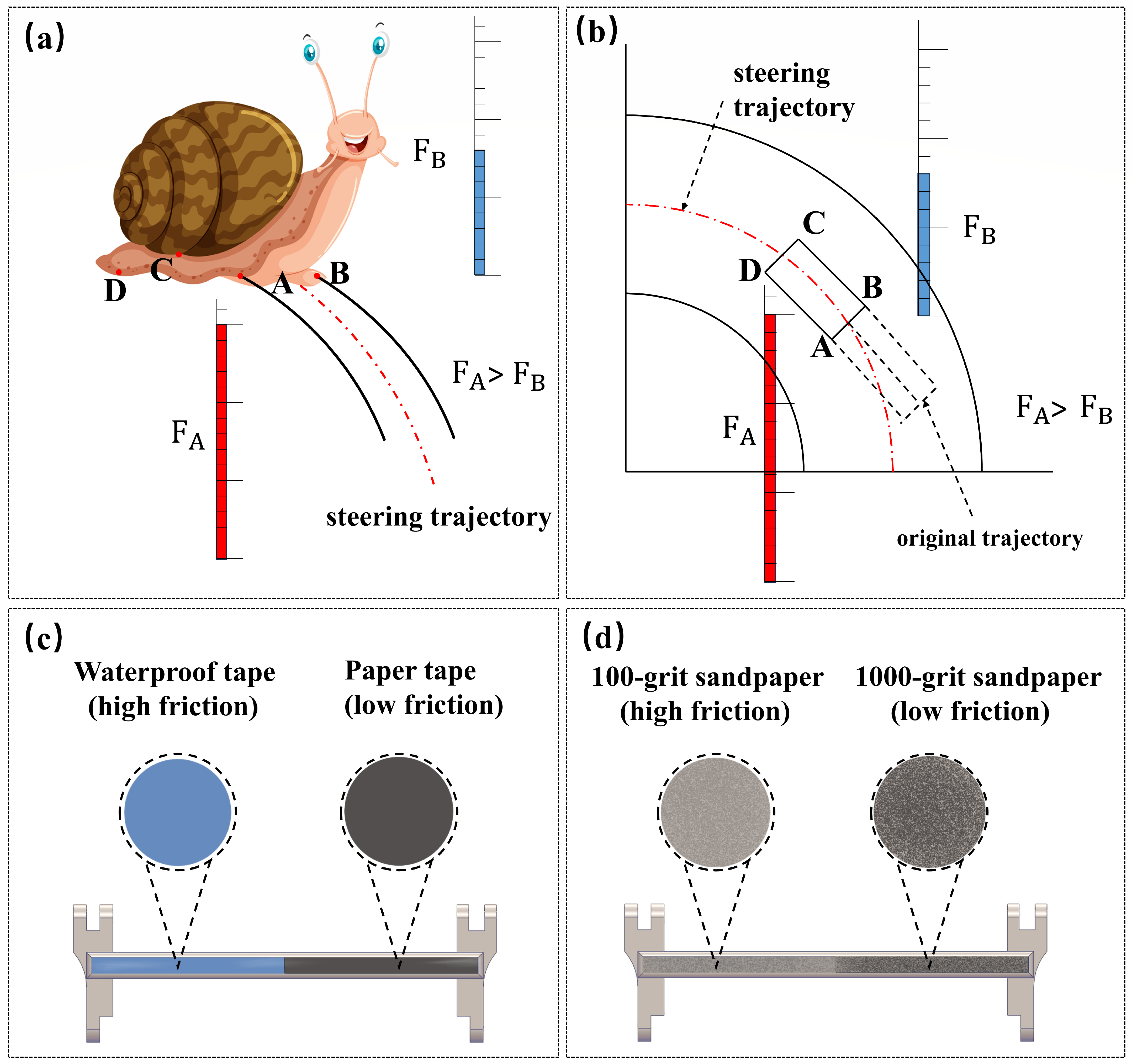
The ventral foot of a snail secretes a substantial amount of mucus, which plays a dual biomechanical role in locomotion: reducing frictional forces while simultaneously enhancing adhesive interactions [19,20,21,22]. Specifically, when a snail selectively secretes mucus on one side of its ventral foot, localized asymmetry in frictional forces arises, thereby modulating its turning behavior, as illustrated in Figure 1a. From a microscopic viewpoint, when the right-front region of the snail’s ventral foot (corresponding to the left-side foot at point A) secretes mucus, the left-front region (corresponding to the right-side foot at point B), with comparatively reduced mucus secretion, comes into contact with the substrate. By modulating pressure via muscular tissues, this region effectively functions as a pivot point, where Fa > Fb. Drawing inspiration from this mechanism, this study introduces a turning principle based on differential friction [23].
Based on the above turning mechanism, this study proposes a novel track design in which the bottom of the track exhibits different friction forces when contacting the ground. Since the normal force, Fn, remains constant during motion, frictional differentiation for turning is achieved by modulating the coefficient of friction. To investigate the impact of frictional asymmetries on the turning angle, three differential-friction experiments are designed to induce turning. The first two experiments involve attaching two distinct types of frictional strips to the left and right sides of the track bottom, as shown in Figure 1c. One device employs waterproof fabric tape and transparent adhesive tape, as shown in Figure 1d, while the other utilizes sandpaper with grit sizes of 100 and 10,000. These materials generate frictional asymmetries, thereby enabling the robot to turn accordingly.
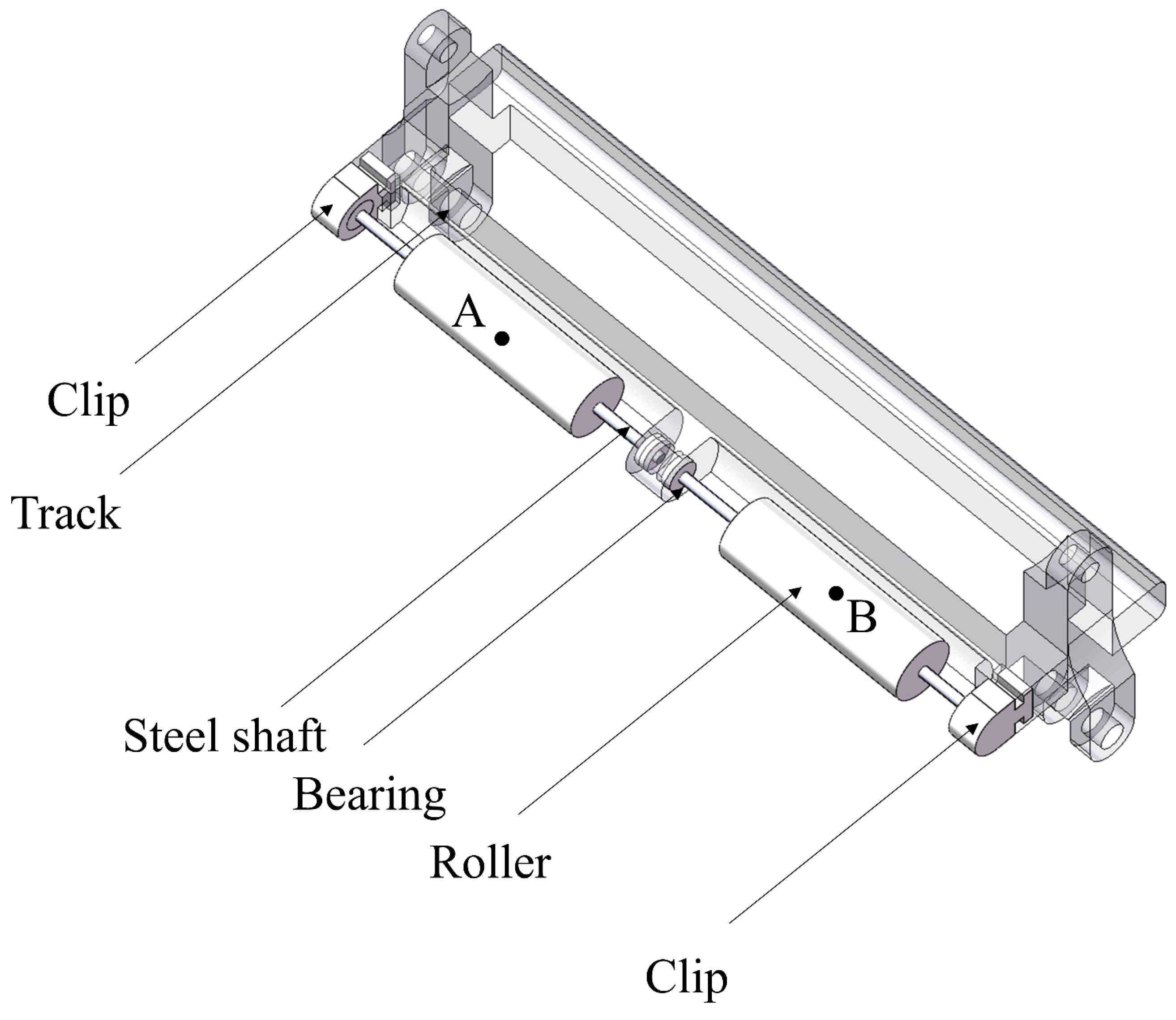
The HCF-SF and LCF-SF experiments achieve frictional differentiation through the use of distinct materials. However, the RSC experiment is specifically designed to induce greater frictional disparity. Since the difference in friction coefficients between different materials on the same substrate is typically limited to two orders of magnitude, this method instead leverages the contrast between rolling and sliding friction to create a difference in friction that can reach approximately three orders of magnitude [24,25,26,27,28]. To achieve this, a customized track structure is designed to amplify the disparity between rolling and sliding friction, thereby facilitating effective turning. As depicted in Figure 2, the key design element for harnessing the contrast between rolling and sliding friction lies in the cylindrical rolling structures installed on the left and right sides of the track bottom. These cylindrical friction elements generate a frictional differential, enabling the robot to turn. To enhance the efficiency of rolling friction, a circular groove is embedded beneath the track to house bearings, thereby reducing resistance between contact surfaces. This structural design optimizes rolling friction and significantly reduces energy loss. The roller comprises two components: a steel shaft, measuring 33 mm in length and 1 mm in diameter and positioned centrally to ensure precise 3D printing. The rigid shaft is then inserted into a cylinder fabricated from epoxy resin, with an inner diameter of 1 mm and an outer diameter of 6 mm. During operation, this outer cylinder makes contact with the ground, while the intermediate rigid shaft and bearing assembly ensure a stable rolling motion. The central slot of the snap, which is designed to accommodate the bearing, adopts an interference fit. During assembly, both ends of the roller are inserted into bearings with an inner diameter of 1 mm and an outer diameter of 3 mm. The bearings are then placed into the snap, which is subsequently pressed into a dedicated slot in the track.
From a mechanical perspective, the proposed track is designed to create a controllable friction asymmetry between the left and right sides of the robot during locomotion. In the material-based configurations, different surface materials are attached to the two sides of the track bottom so that the two sides experience different tangential resistances when contacting the same substrate. In the rolling–sliding configuration, one side retains sliding contact, while the other side is equipped with cylindrical rolling elements, thereby converting part of the contact mode from sliding to rolling. This arrangement reduces the resistance on one side while maintaining higher resistance on the other side, thereby generating a net steering moment during forward motion.
The rolling elements are integrated into the track through a compact shaft–bearing–slot assembly. Each roller consists of a rigid shaft and an outer cylindrical element in contact with the ground. The shaft is supported by miniature bearings seated in dedicated slots in the track, ensuring stable rolling motion and reducing parasitic resistance. This design enables the friction differential to be generated structurally, without introducing an additional steering actuator.

2.2. Experimental Environment

All experiments were conducted on the same flat substrate and under identical operating conditions so that the steering differences among the tested configurations could be attributed primarily to the imposed friction asymmetry. The measurements focused on the displacement trajectory, steering angle, and forward velocity of the robot head during locomotion. The directly obtained experimental data were the time–displacement relationship and the time–steering angle relationship, and the main measurement sensor used in the experiments was a laser rangefinder. The velocity profiles were obtained by differentiating the displacement data with respect to time.
The nine images presented in the Section 2.2 correspond to frames captured at 1 s intervals over a total experimental duration of 9 s. To improve measurement reliability, each data point was obtained from three repeated measurements, and the average value was used for subsequent analysis, thereby reducing random measurement errors and improving the repeatability of the reported displacement, steering angle, and velocity data. The experimental results are presented as mean ± standard deviation, and error bars were included in the relevant plots to reflect the variability among repeated trials. During each experiment, the position of the circular notch on the robot head was recorded once per second. In particular, at the third second, the experiment was paused for 3 s to ensure accurate recording of the robot-head position.
To determine the steering state of the robot, the vertical displacement y and horizontal displacement x of the robot head were measured with respect to a reference line. For the measurement of the vertical displacement, the laser rangefinder was aligned parallel to the reference line, and the distance to the reference point at the center of the robot head was recorded. The horizontal displacement was obtained indirectly from the measured hypotenuse length of the corresponding right triangle. During this measurement, the laser rangefinder was positioned behind the reference line, and the emitted laser was aligned with the steering reference line of the robot head to determine the hypotenuse length.
Based on the measured x and y values, the steering angle θ was calculated according to the geometric relationship given in Equation (1), where θ is the steering angle of the robot, x is the horizontal displacement, and y is the vertical displacement.
θ = a r c c o s y y 2 + x 2
The displacement trajectories shown in the figures were reconstructed from the measured x-y coordinates of the robot head. The velocity profiles presented in the experimental section were not measured directly, but were obtained by differentiating the displacement data with respect to time under the same sampling interval. Thus, the experimental setup provides mutually consistent measurements of trajectory, steering angle, and velocity to compare the steering performance of different friction-differential configurations.

3. Experimental Results

3.1. Low Coefficient of Friction Sliding Friction Experiment

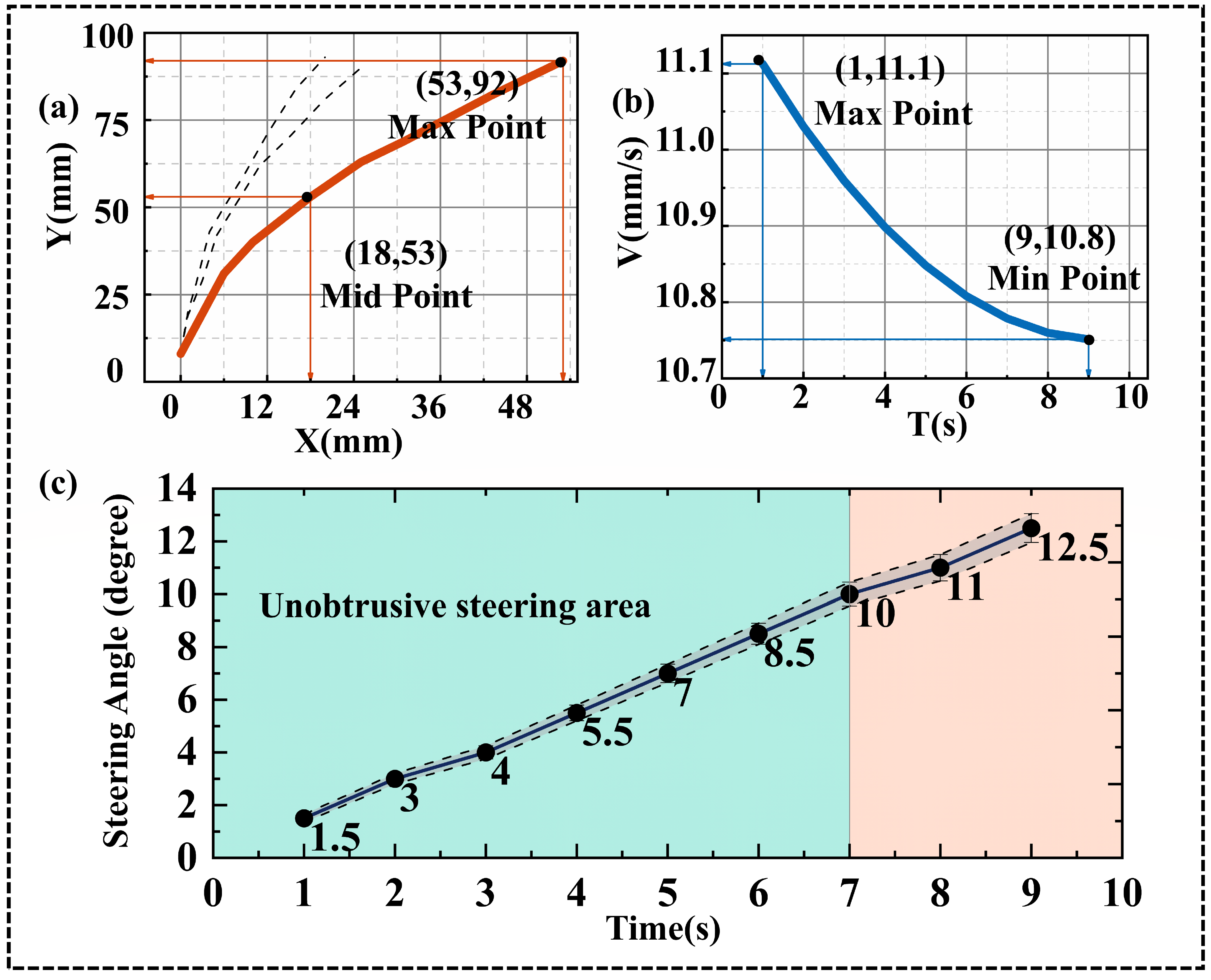
In the LCF-SF experiment, two distinct materials were mounted at the bottom of the track to simulate the turning phenomenon caused by frictional differences. As shown in Figure 3a–c, the experimental results are presented in three parts: Figure 3a illustrates the displacement trajectory of the robot. Figure 3b presents the time–speed profile, and Figure 3c shows the evolution of the steering angle over time. Together, these three subfigures characterize the steering performance of the robot.
In Figure 3c, the x-axis represents time, while the y-axis denotes the steering angle (θ). In this study, a steering angle of 10° or greater is defined as the onset of noticeable steering. Accordingly, the data points beyond this threshold are highlighted in the figure using a contrasting background color to indicate the stage where steering becomes more evident.
Subscript 1 corresponds to the first experimental frame captured at 1 s, where the robot exhibits a y-axis displacement of 11 mm and a turning angle of 1.5°. As the experiment proceeds, the steering angle increases gradually. At 7 s, the steering angle reaches 10°, indicating the onset of noticeable steering according to the criterion adopted in this study. By the final second (9 s), the steering angle reaches 12.5°, with a y-axis displacement of 90 mm and an x-axis displacement of 12.5 mm. Based on curve fitting, the steering angular velocity in this experiment is calculated as ω = 1.4.
Figure 3 shows that the LCF-SF configuration produces a gradual but relatively mild steering response. The displacement trajectory in Figure 3a indicates cumulative lateral deviation during forward locomotion, while Figure 3b shows that the robot maintains continuous motion during the turning process. Figure 3c further demonstrates that the steering angle increases progressively with time and only reaches the noticeable steering threshold in the later stage of motion. These results confirm that the friction differential in the LCF-SF configuration is sufficient to induce steering; however, its turning effect remains weaker than that observed in the HCF-SF and RSC configurations.
Figure 3. Results of the LCF-SF experiment. Panel (a) shows the displacement trajectory of the robot. Panel (b) presents the time–speed profile, and panel (c) illustrates the evolution of the steering angle over time. The highlighted region in panel (c) indicates the stage of more evident steering, which is defined as a steering angle of 10° or greater in this study. Error bars represent the standard deviation of three repeated measurements.
Lubricants 14 00173 g003

3.2. High Coefficient of Friction Sliding Friction Experiment

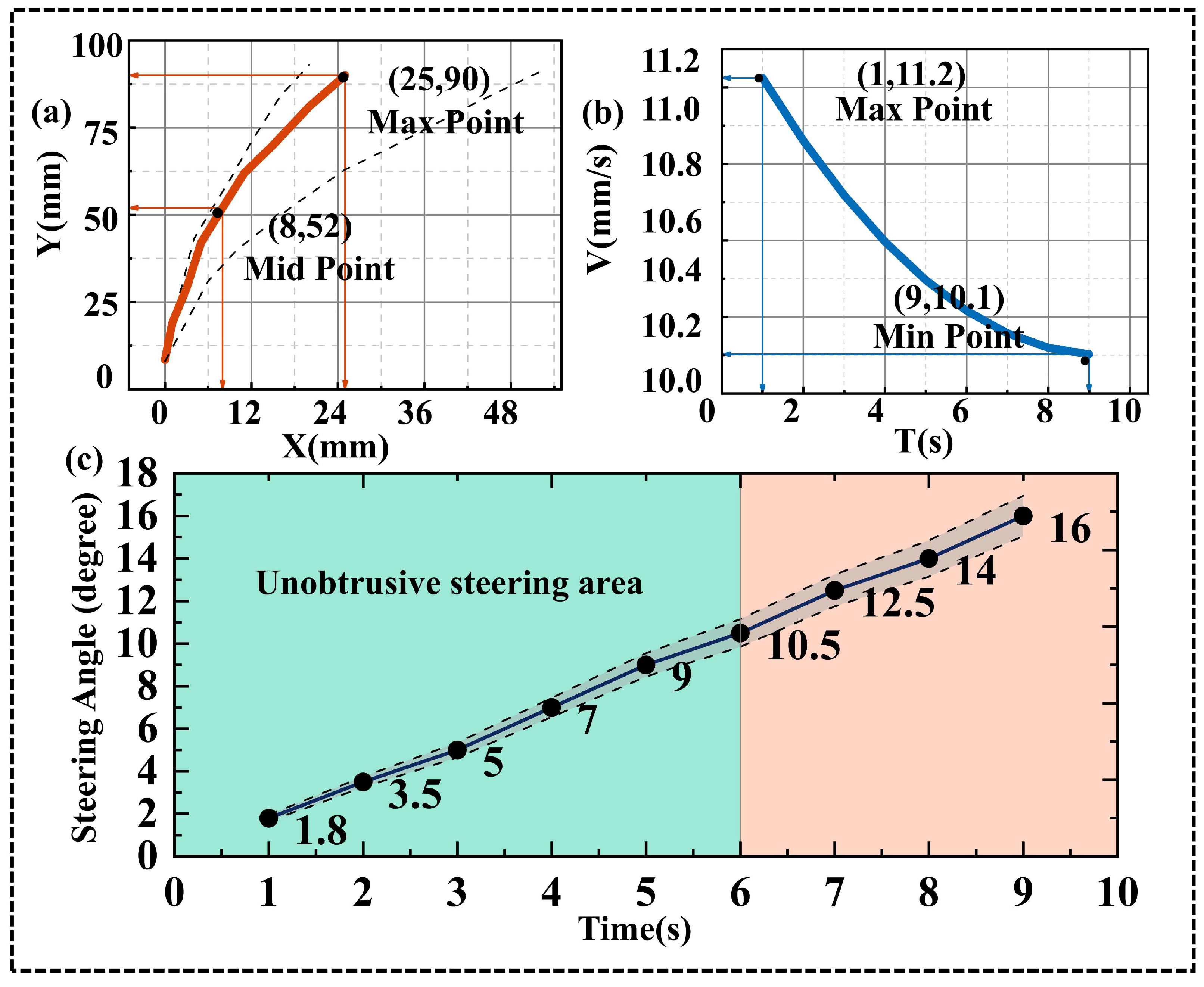
The HCF-SF experiment (Figure 4) follows the same principle as the LCF-SF experiment but employs sandpaper materials with different grit sizes to generate a larger friction differential. As a result, the steering performance is improved compared with the LCF-SF case.
In this experiment, noticeable turning appears at approximately 6 s, where the steering angle reaches 10.5°, with a y-axis displacement of 60 mm and an x-axis displacement of 8.5 mm. This behavior can be explained by the progressive accumulation of friction-induced steering moments during locomotion. As the robot propagates peristaltic waves along the track, the difference in tangential resistance between the two sides continuously produces a net steering moment. Once this accumulated moment becomes sufficiently large, the turning behavior becomes clearly observable in the trajectory and steering-angle curve. Because the sandpaper materials used in the HCF-SF configuration generate a larger friction coefficient difference than the materials used in the LCF-SF experiment, the steering threshold is reached earlier, which explains the more evident turning observed around 6 s.
Ultimately, the experiment achieves a total turning angle of 16°, which is 3.5° larger than that obtained in the LCF-SF experiment. The final y-axis displacement is 91 mm, showing minimal variation compared with Experiment 1. Based on curve fitting, the steering angular velocity in this experiment is calculated as ω = 1.79. Although the turning angle increases gradually over time, the overall steering response remains moderate compared with the RSC experiment.
Figure 4. Overview of the HCF-SF experiment. Panel (a) shows the displacement trajectory of the robot. Panel (b) presents the time–speed profile, and panel (c) illustrates the evolution of the steering angle over time. The figure indicates that the robot appears to turn significantly at the 6 s mark. Error bars represent the standard deviation of three repeated measurements.
Lubricants 14 00173 g004

3.3. Rolling vs. Sliding Friction Comparison Experiment

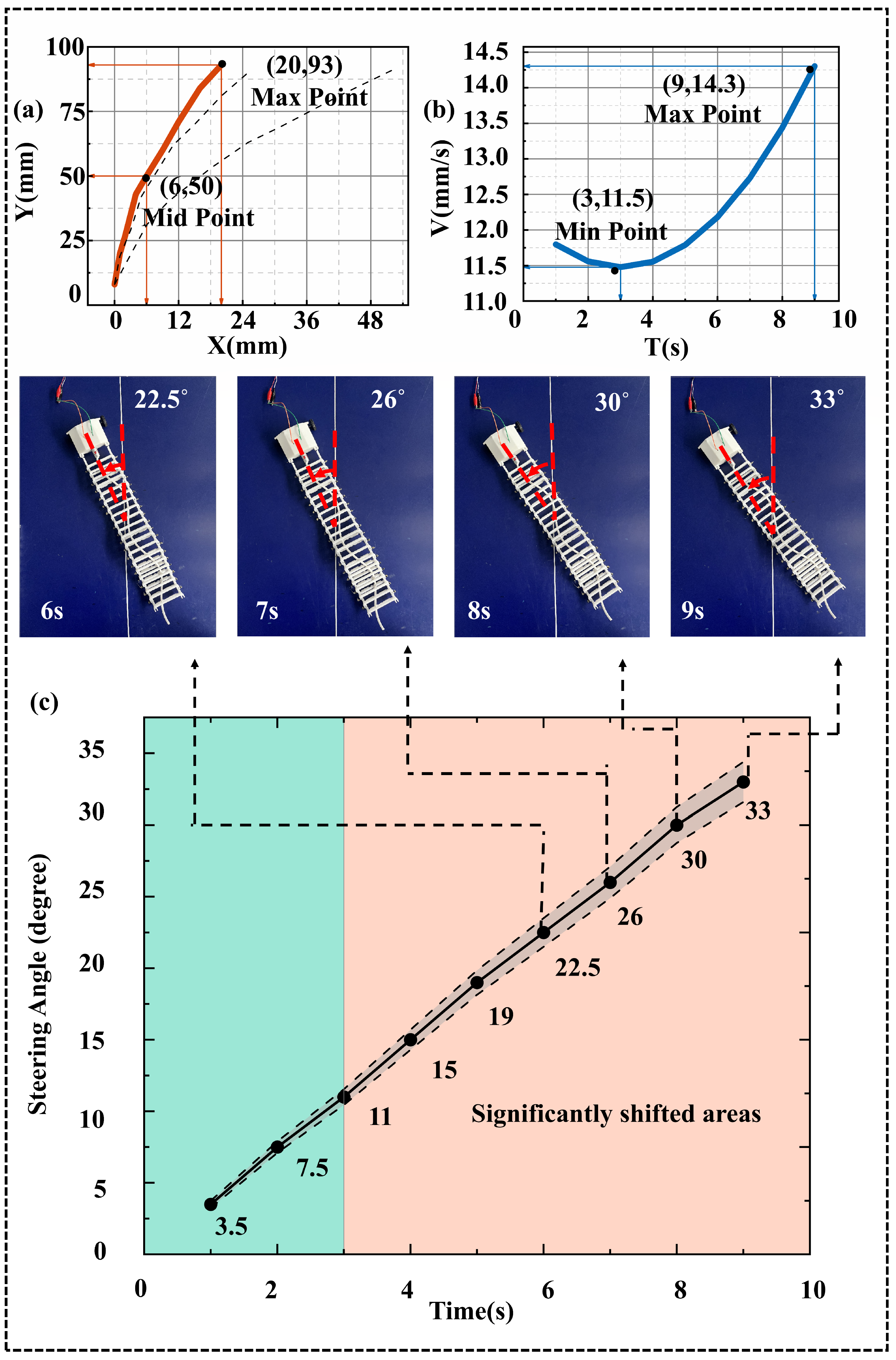
To achieve a more pronounced turning effect, this study exploits the contrast between sliding friction and rolling resistance to generate a larger friction differential and, consequently, larger turning angles. Compared with the material-based cases in the previous two experiments, the contrast between sliding and rolling contact can produce a much greater difference in tangential resistance at the track–ground interface. This larger friction differential generates a stronger imbalance in the left–right tangential resistance, thereby increasing the net steering moment acting on the robot and leading to a higher steering angular velocity Figure 5. This trend is also consistent with the theoretical model developed in Section 4.2, where the resultant steering moment is proportional to the difference between the sliding-friction term and the rolling-resistance term. As the friction differential increases, the resulting moment and angular velocity increase accordingly, which explains the larger turning angles observed in the experiments. In addition, the rolling elements reduce the resistance on one side of the track while maintaining higher sliding resistance on the opposite side, thereby continuously generating a directional moment during forward locomotion.
Figure 5. Overview of the RSC experiment; Panel (a) shows the displacement trajectory of the robot. Panel (b) presents the time–speed profile, and panel (c) illustrates the evolution of the steering angle over time. the robot begins to exhibit noticeable turning at approximately 3 s. Error bars represent the standard deviation of three repeated measurements.
Lubricants 14 00173 g005
Accordingly, the turning effect in the RSC experiment is significantly enhanced. Noticeable turning appears as early as the third second, whereas in the previous two experiments, it only became evident at approximately the seventh second. At this time, the y-axis displacement reaches 33 mm, and curve fitting yields an angular velocity of ω = 3.7, which is nearly twice that observed in the previous two experiments. By the end of the experiment, the final turning angle reaches 33°, with a y-axis displacement of 95 mm and an x-axis displacement of 13 mm. These results indicate that increasing the friction differential is an effective way to enhance the steering capability of the robot. The RSC configuration therefore provides a stronger and faster steering response compared with the material-based friction-differential configurations, demonstrating the effectiveness of combining rolling and sliding friction to amplify the turning behavior of the system.
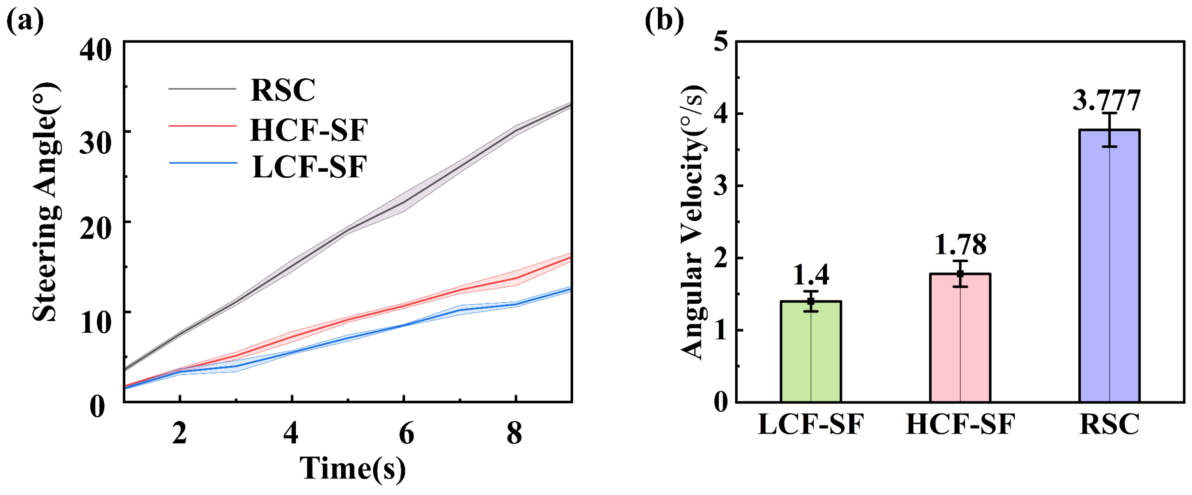
The three curves in Figure 6a depict the turning angle–time relationships for the three experiments. As shown in the figure, the turning effect of the RSC experiment is the most pronounced, with the distinct turning phase reached in just 3 s—a 6 s improvement compared to both the HCF-SF and LCF-SF experiments. After performing linear fitting on the scatter plots from the three experiments, the results are visualized in the bar chart (Figure 6b). This chart demonstrates that the RSC experiment achieves the highest angular velocity of 3.777, representing an increase of 2.377 compared to the LCF-SF experiment and 1.997 compared to the HCF-SF experiment. Overall, while the use of different materials can create differences in friction coefficients and thereby enable turning, the frictional contrast remains relatively modest, resulting in suboptimal turning performance. However, by exploiting the contrast between rolling and sliding friction, the RSC experiment generates a substantially larger friction coefficient differential, leading to significant improvements in both the turning rate and the time required to reach the noticeable turning phase. The results of the LCF-SF and HCF-SF experiments indicate that using different materials can induce frictional differences, thus enabling rotation. However, the friction coefficients of various materials on the same substrate differ by no more than two orders of magnitude. Given that bioinspired snail robots require more efficient steering for future applications, the material-based approach should be replaced by a more effective method. Consequently, this study employs an approach capable of achieving a greater friction differential—namely, exploiting the contrast between sliding and rolling friction for steering.

3.4. Multi-Factor Validation Experiment

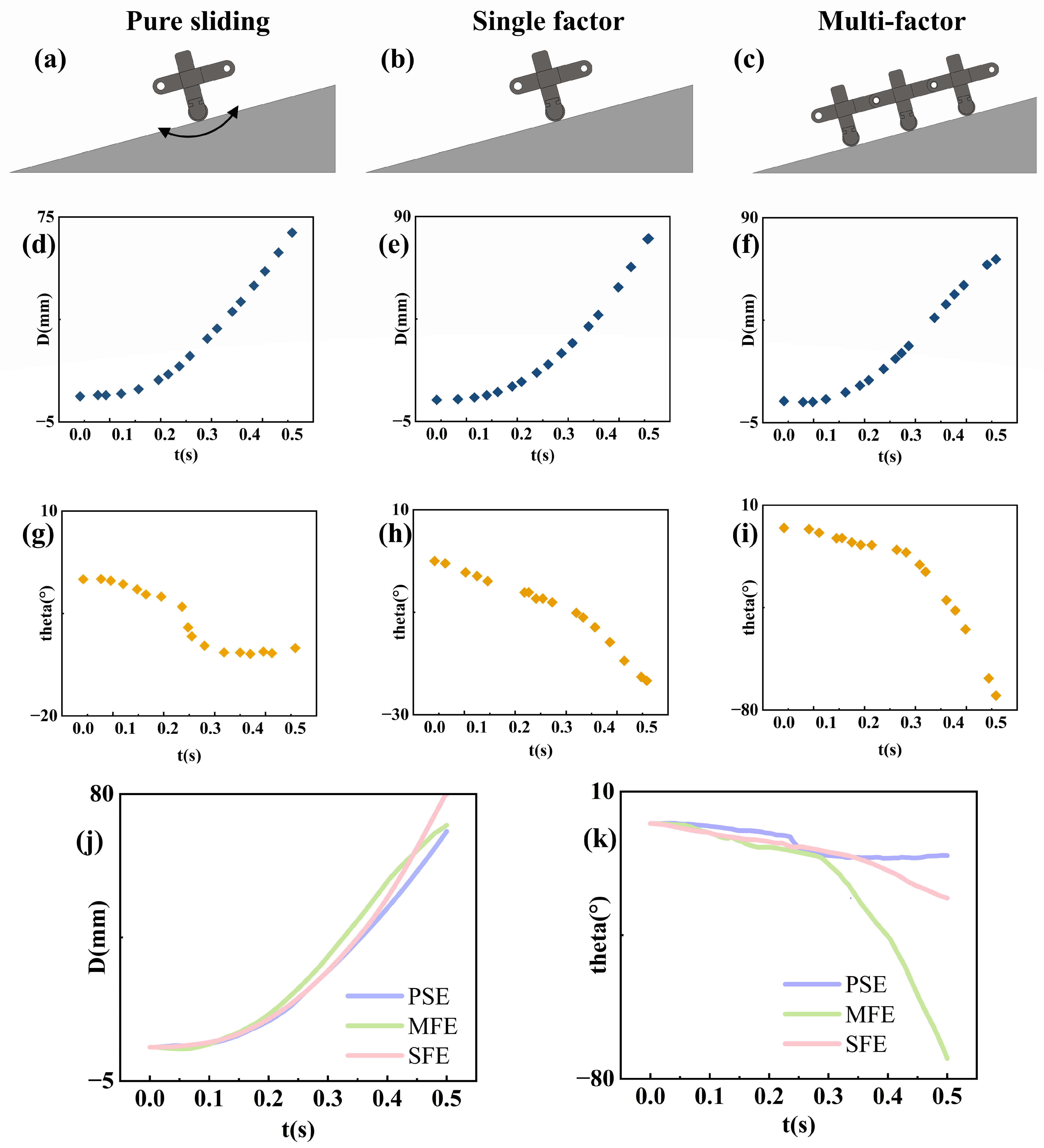
As shown in Figure 7, panels a, b, and c correspond to the Pure Sliding Experiment (PSE), the Single-Friction-Difference Experiment (SFE), and the Multi-Friction-Difference Experiment (MFE), respectively. The PSE represents the case without friction differential, in which the steering behavior is dominated only by sliding friction. The SFE includes only one friction-differential element, whereas the MFE incorporates multiple friction-differential elements acting together. The experimental results were obtained using the RECURDY simulation platform. In the simulation setup, the slope angle was set to 30°. All components in the model were treated as rigid bodies. In the PSE configuration, both sides of the track were modeled as sliding-contact elements, with a friction coefficient of μ = 0.30 against the slope surface, and the contact was defined as solid contact. In this case, the roller components were connected to the track body by fixed constraints. In the SFE configuration, the roller components on the two sides were assigned different constraint conditions: one side was connected to the track body by a fixed constraint, whereas the other side was connected through a revolute joint, thereby producing a contact difference between the two sides. In the MFE configuration, the same friction-differential principle as in the SFE case was retained, but the number of track units was increased from one to three. Except for the increased number of track units, the remaining settings in the MFE configuration were the same as those in the SFE configuration.
In this comparison, the PSE serves as the baseline case, while the SFE is used to verify the steering effect introduced by a single friction-differential element. The MFE is further compared with the SFE to investigate the difference between a single friction-differential element and multiple friction-differential elements under the same friction-differential principle.
As shown in Figure 7g–i, the plots present the variation in steering angle with time. Under condition G, the maximum steering angle remains within approximately 12° in all three experiments, indicating that the robot exhibits almost no obvious steering. This is because the friction differential under this condition is too small to generate a sufficiently effective steering moment.
Under condition H, the maximum steering angle increases to about 30°. Compared with the PSE, this result indicates that the introduction of friction differential can effectively generate steering behavior. Under condition I, the maximum steering angle further increases to about 80°, which is nearly three times that observed under condition H in the SFE-related comparison. By comparing Figure 7j,k, it can be seen that friction differential enables steering, and that the steering performance is further improved as the number of friction-differential elements increases.
Overall, the results demonstrate that friction differential is the key factor in producing steering, while the use of multiple friction-differential elements can further enhance the steering effect.

4. Discussion

4.1. Rolling and Sliding Friction Based on Novel Tracks

The fundamental differences between sliding friction and rolling resistance lie in the contact mode, the mechanism of friction generation, the manner of energy dissipation, and the resulting tangential resistance. In the bioinspired snail robot, sliding friction occurs when materials such as tape or sandpaper remain in relative sliding contact with the ground. This friction mainly arises from the interlocking and shearing of microscopic surface asperities, together with intermolecular adhesive interactions between the contacting surfaces. Under the simplified conditions considered in this study, the magnitude of sliding friction is assumed to be proportional to the normal load and the sliding friction coefficient and is generally treated as independent of the apparent contact area [29,30,31,32], following the classical Coulomb friction law commonly used in contact mechanics and tribology. To avoid ambiguity, it should be emphasized that rolling friction (more precisely, rolling resistance) is explicitly considered in this study. In particular, the RSC experiment exploits the contrast between sliding friction and rolling resistance to generate a larger friction differential, and the rolling-contact side is modeled using an equivalent rolling-resistance formulation in the theoretical analysis.
By contrast, the rolling-contact side is associated with rolling resistance rather than sliding friction. This resistance mainly originates from elastic deformation in the contact region, internal material dissipation, and localized microscopic slip at the contact points. Compared with sliding friction, rolling resistance generally produces lower energy dissipation and smaller tangential resistance under comparable loading conditions, as the primary energy loss mechanisms are elastic deformation in the contact region and localized microscopic slips rather than large-scale surface shearing [33,34,35].
In the present theoretical model, these two contact modes are described using a simplified quasi-static friction formulation. For the sliding-contact side, tangential resistance is modeled using the classical Coulomb friction law, in which the sliding friction force is proportional to the normal load, with
F A = μ s   N
where
F A is the sliding friction force on the left roller;
μ s is the sliding friction coefficient (dimensionless);
N is the normal force acting on the roller.
For the rolling-contact side, the resistance is not described using Coulomb sliding friction. Instead, it is represented using an equivalent rolling-resistance model. In this formulation, the rolling resistance is first expressed as a resisting moment, with
M r = N c r
where
M r is the rolling-resistance moment;
c r is the rolling-resistance coefficient.
F B = M r r = N c r r
where
F B is the equivalent tangential force associated with rolling resistance on the right side;
r is the radius of the roller.
Therefore, the present theoretical model does not adopt a single friction law for all contact states. Instead, the sliding-contact side follows the classical Coulomb friction law, whereas the rolling-contact side is represented by an equivalent rolling-resistance model. This simplified formulation captures the dominant steering mechanism generated by left–right friction asymmetry while avoiding the complexity of a full contact-mechanics description.
It should be noted that in practical tribological systems, the effective friction coefficient may depend on multiple factors, including normal pressure, sliding velocity, surface roughness, temperature, and environmental humidity. In the present study, the friction coefficients are treated as effective parameters under controlled experimental conditions so that the primary steering mechanism caused by friction asymmetry can be clearly analyzed.
To keep the model analytically tractable, a simplified Coulomb-type friction formulation is adopted in which the friction force is assumed to be proportional to the normal load. In reality, friction behavior may exhibit nonlinear characteristics and may vary with operating conditions such as sliding velocity, contact pressure, and surface properties. However, these factors mainly affect the quantitative magnitude of friction and do not alter the fundamental principle of friction-differential steering considered in this work.
In addition, the model is developed under a quasi-static assumption; therefore, dynamic effects such as inertial coupling, transient contact variations, and velocity-dependent friction are not explicitly included. These effects may influence the quantitative steering response of the robot, particularly at higher locomotion speeds.
Furthermore, the present study primarily focuses on validating the feasibility of friction-differential steering and does not include a detailed energy efficiency analysis. The energy expenditure associated with overcoming frictional resistance and its influence on locomotion efficiency will be investigated in future work through dedicated experiments and dynamic modeling.

4.2. Physical Modeling of Single Friction Elements

The following model is intended as a simplified quasi-static, mechanism-level description of friction-differential steering. Its purpose is to capture the first-order relationship between friction asymmetry and steering response, rather than to establish a full quantitative contact-mechanics model of the robot–ground interaction. Accordingly, several quantities in the model are treated as effective lumped parameters under the present experimental conditions, rather than independently measured physical constants. Therefore, the present model should be understood primarily as a qualitative and trend-oriented analytical framework for mechanism interpretation, rather than as a fully predictive quantitative model validated by independently measured parameters.
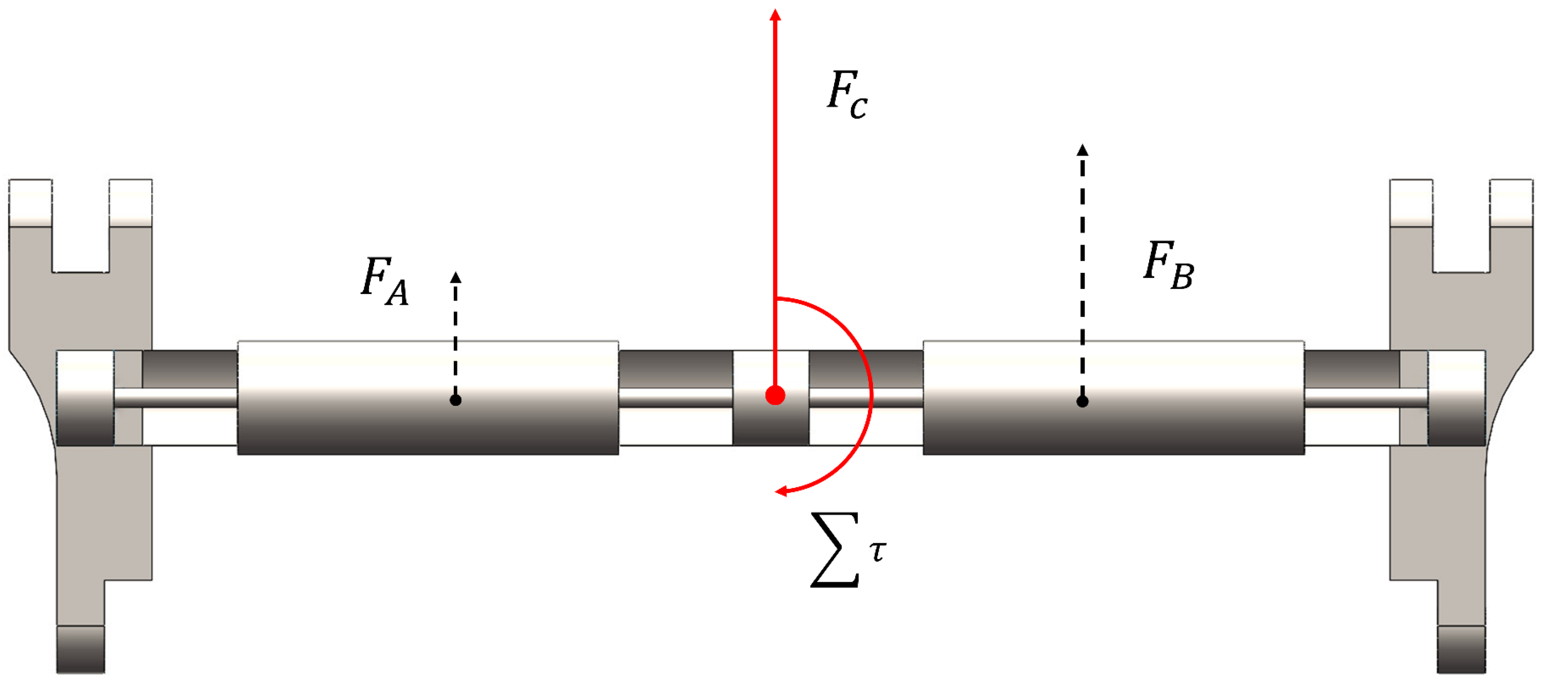
A tracked mechanism exploiting frictional differences is illustrated in Figure 8, where force vectors are indicated by arrows, with lever arms a and b satisfying a:b = 1:2. Upon contact with the ground, the left roller is prevented from rolling and undergoes sliding friction, denoted as F A . Let N denote the normal force. The sliding friction is therefore expressed according to the classical Coulomb friction law.
F A = μ s N
On the right, rolling friction occurs at the contact interface with the ground, denoted as F B . Let c r be the rolling-resistance coefficient and r be the roller radius. The rolling friction force is
F B = N c r r
The resultant of F A and F B is denoted as F c . To analyze the rotational effect, the forces F A and F B are equivalently applied to the central point O. The moment generated by F A about point O is denoted as M A , with the perpendicular distance from the line of action of F A to O given by L:
M A = F A L
where
M A is the moment produced by F A about point O;
L is the moment arm corresponding to F A .
Similarly, the moment of F B about point O is denoted as M B . As F B generates a moment in the opposite rotational direction, it is considered negative:
M B = F B L
where
M B is the moment produced by F B about point O;
L is the moment arm corresponding to F B .
The total moment about point O is then expressed as τ , which is obtained by summing M A and M B . Substituting Equations (5) and (6) yields
τ = L N μ s r c r r
where
τ is the resultant moment about point O.
The total force acting on the track segment is the sum of F A and F B , and the resultant moment is τ . Under the action of this combined moment, the track segment rotates. Assuming the rotation radius of the track is R, the moment of inertia is I, and the angular acceleration is α, the relationship between the moment and angular acceleration is
τ = I α = L N μ s r c r r
where
α is the angular acceleration.
From the differential relationship between angular acceleration and angular velocity, the angular velocity of the resultant moment relative to point O is denoted as w, with
w = a   d t = L N μ s r c r I r d t
where
  w is the angular velocity of the track segment.
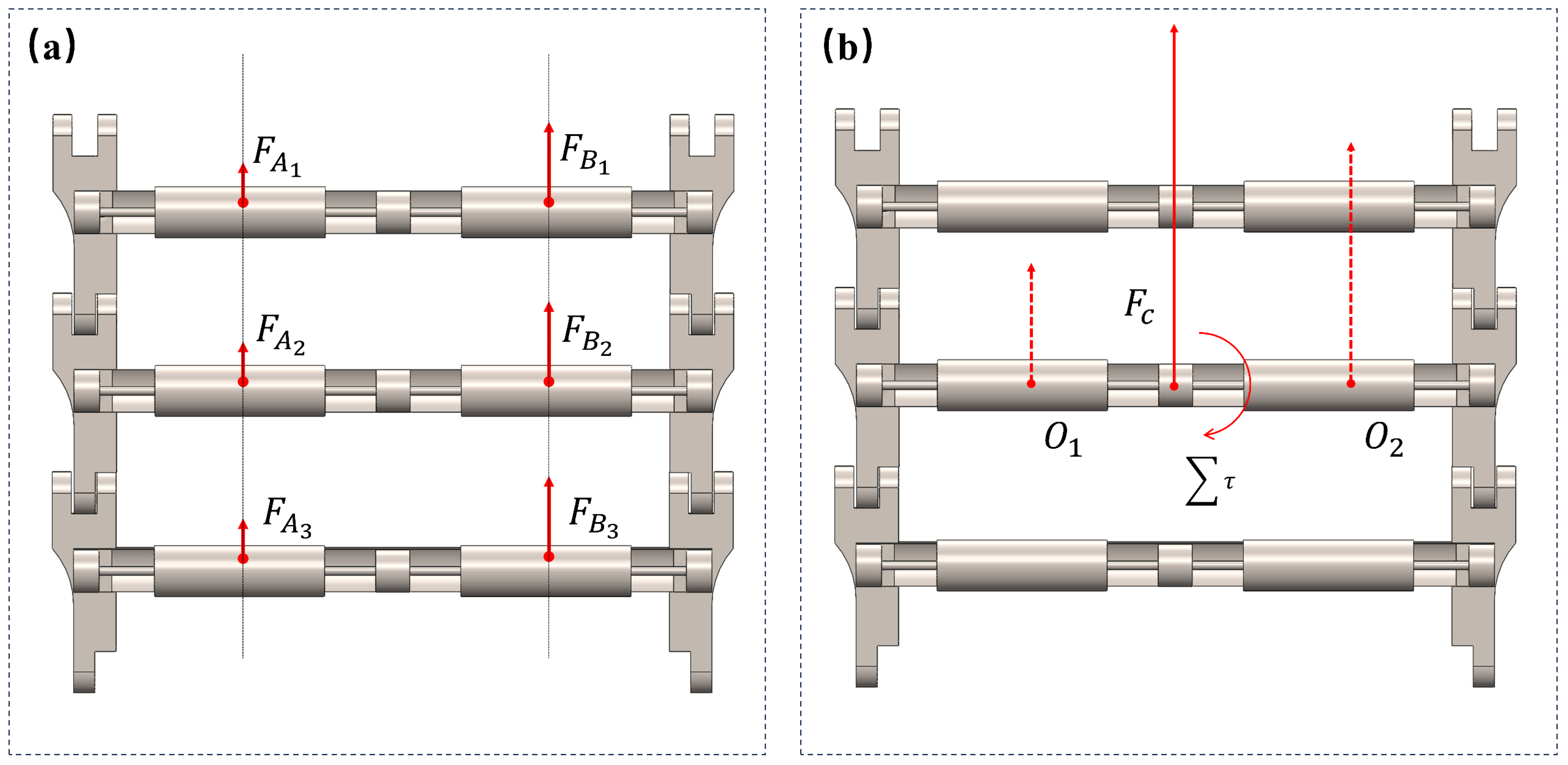
When multiple friction-differential elements act simultaneously, as in the present study with multiple tracks enabling the robot to undergo friction-differential steering (Figure 9a), the individual forces along the same line can be combined according to rigid body dynamics. Specifically, the forces F A 1 ,   F A 2 ,   a n d   F A 3 are collinear and can be translated along their lines of action to produce a single resultant force acting at point O 1 . Similarly, F B 1 , F B 2 , a n d   F B 3 are combined at point O 2 .Therefore, the resultant force acting on the system is.
F C = 3 N μ s + r c r r
where
F c is the total force acting on the track segment.
Consequently, the angular velocity of the track segment under this combined force is
w = a   d t = 3 L N μ s r c r I r d t
This framework allows further analysis of the motion of any point on the peristaltic robot at a given instant, accounting for both translational and rotational contributions arising from friction differentials.
A point on the robot undergoes two simultaneous velocities during motion:
  • A linear velocity, V b , perpendicular to the bottom of the track due to the frictional interaction with the ground.
  • An angular velocity, w, induced by the friction differential across the track.
The relationship between angular and linear velocities is given by
v a = w R
where
v a is the tangential velocity due to angular rotation;
w is the angular velocity of the track segment;
R is the radius of rotation.
Decomposing v a into the x and y components yields
where
( v x , v y ) are the velocity components in the horizontal and vertical directions;
θ is the instantaneous orientation of the track relative to the reference axis.
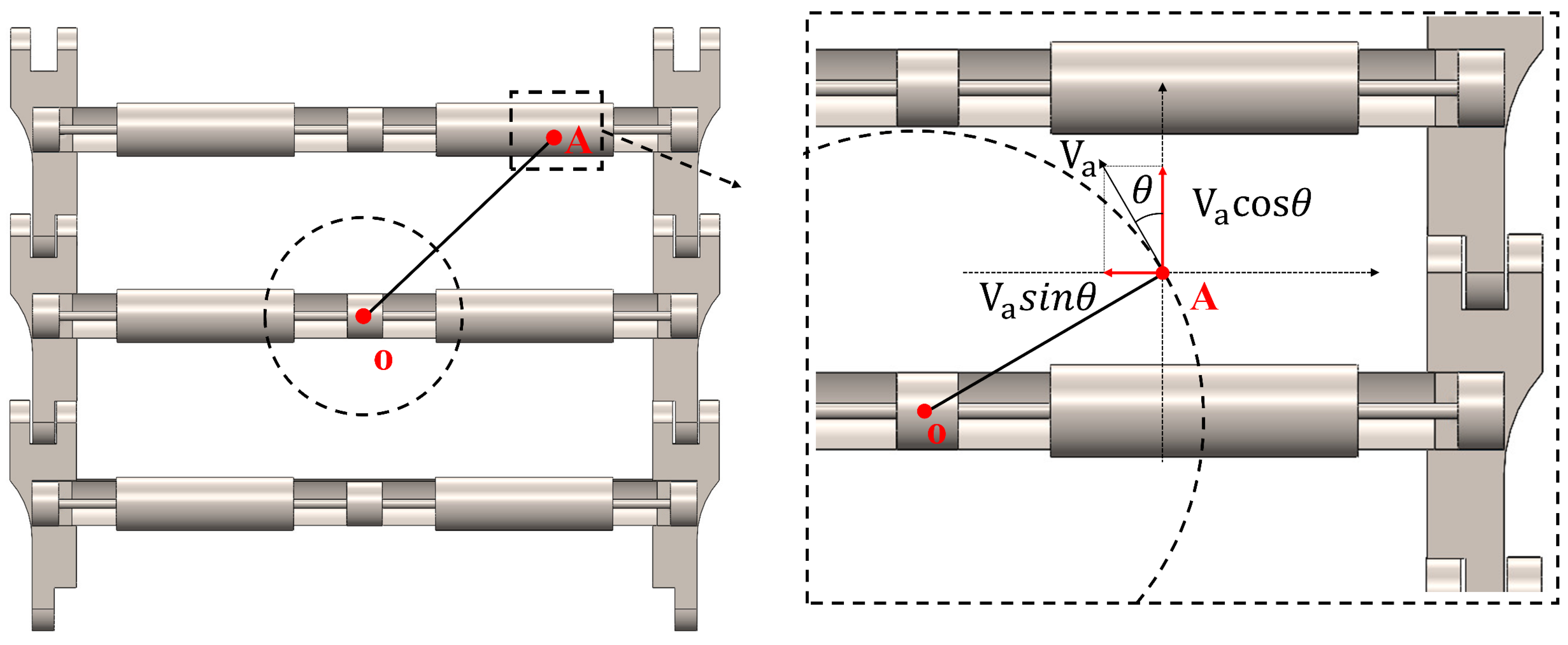
By substituting the expression for v a derived from the angular acceleration analysis, and with reference to the velocity analysis diagram in Figure 10, we obtain:
v x = R 3 L N μ s r c r I r c o s θ d t v y = v b + R 3 L N μ s r c r I r s i n θ d t
Figure 10. The motion state of an arbitrary point during the robot’s locomotion. Point A denotes an arbitrary point on the track, while O represents the geometric center of the robot, which is assumed to behave as a rigid body.
Lubricants 14 00173 g010
Finally, integration over time to the relative position of velocity yields
X x = R 3 L N μ s r c r I r c o s θ d t d t Y y = v b + R 3 L N μ s r c r I r s i n θ d t d t
where
  X x denotes the position coordinate of an arbitrary point on the robot along the x (horizontal) direction.
  Y y denotes the position coordinate of an arbitrary point on the robot along the y (vertical) direction.

4.3. Steering with Different Effects Caused by Different Friction Differences

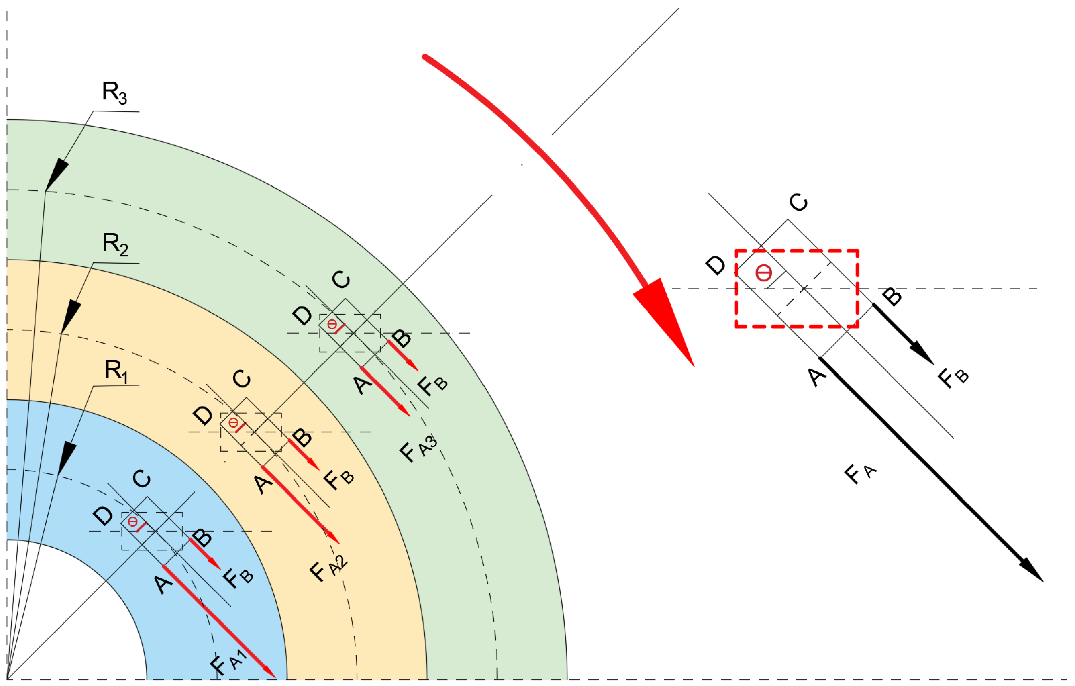
Figure 11 depicts the runway model corresponding to different steering effects under varying frictional differences based on the experimental findings, together with the theoretical analysis of friction-differential steering. The bottom of the bioinspired snail robot is represented by a theoretical model, consistent with the previous analysis, in which a rectangular shape is used as a substitute. Point A corresponds to the front-left section of the bottom, while point B corresponds to the front-right section. The black directed arrows represent force vectors, with their lengths indicating the magnitudes of the forces.
The red dashed line represents the reference trajectory of the theoretical model when no turning occurs, while θ denotes the angle between the theoretical model and the actual trajectory during turning.
The figure illustrates the theoretical turning model derived from the experimental data. R1, R2, and R3 represent the turning radii corresponding to the theoretical models. Fa and Fb denote the frictional forces on the left and right sides of the track and the snail robot, respectively, with Fa > Fb. Due to the frictional difference, all three theoretical models (1, 2, and 3) follow the trajectories indicated by the red curved arrows.
Furthermore, as the frictional difference increases, with Fa further augmented, the turning trajectory gradually shifts from the outermost circle to the innermost circle, corresponding to the trajectories indicated in green, yellow, and blue in the figure. As shown in the figure, Fa1 > Fa2 > Fa3, leading to a progressive reduction in the turning radius such that R1 > R2 > R3.

4.4. Inferences from Physical Models

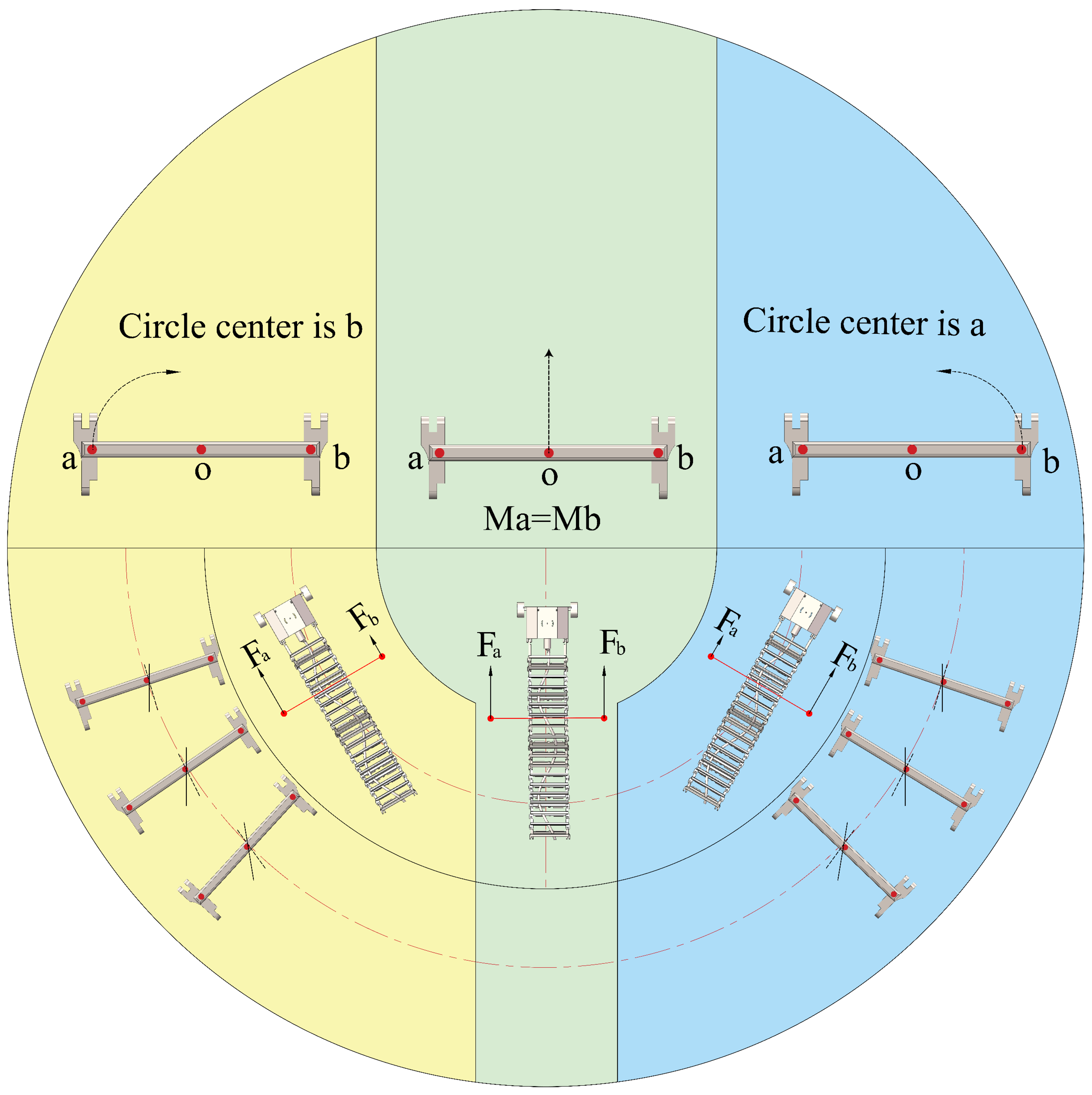
Figure 12 schematically illustrates the steering behavior of the bioinspired snail robot under different left–right friction distributions, based on both experimental observations and the proposed friction-differential model. The figure is divided into three distinct regions according to the relative magnitude and sign of the frictional difference between the two sides of the track.
The central region represents the condition of approximately balanced friction ( F A F B ), where the tangential resistances on both sides are nearly equal. In this case, the generated steering moments on the left and right sides are counterbalanced ( M A = M B ), resulting in a negligible net steering moment. Consequently, the robot exhibits approximately straight locomotion along its forward direction.
The left region corresponds to the condition where the frictional resistance on the right side is greater than that on the left side ( F B > F A ). This asymmetry produces a net steering moment that causes the robot to rotate toward the left side, leading to a left-turning trajectory. Conversely, the right region represents the opposite case ( F A > F B ), where the larger friction on the left side induces a steering moment in the opposite direction, causing the robot to turn right.
Furthermore, as the magnitude of the friction differential | F A F B | increases, the imbalance in tangential resistance becomes more significant, resulting in a larger steering moment and a reduced turning radius. This trend is consistent with both the experimental results and the theoretical analysis.
Overall, Figure 12 clearly demonstrates the fundamental mechanism of friction-differential steering: balanced friction leads to straight motion, whereas asymmetric friction generates directional steering, with the turning direction determined by the side with greater friction.
In biological systems, snail locomotion is generally characterized by relatively low speed and considerable energy expenditure due to the rheological properties of mucus and the peristaltic propagation of foot waves. However, the objective of the present study is not to reproduce the complete biological locomotion of snails but rather to extract the underlying friction-differential steering principle and apply it to robotic locomotion. Unlike real snails, the robot proposed in this work does not rely on mucus secretion. Instead, friction asymmetry is generated structurally through differences in surface materials or through the contrast between sliding and rolling contact.
Consequently, the proposed steering mechanism is not intrinsically limited to low-speed operation. In principle, friction-differential effects can still generate a net steering moment at higher locomotion speeds. However, velocity-dependent friction characteristics and dynamic effects may influence the quantitative steering response, and these aspects require further investigation.
Compared with other biomimetic locomotion systems—such as snake-inspired robots that rely on body bending and anisotropic ground reaction forces, or worm-inspired robots that employ periodic anchoring–release mechanisms—the present approach achieves steering through passive frictional asymmetry at the track–ground interface. This strategy eliminates the need for additional steering actuators and avoids large-amplitude body deformation, thereby reducing mechanical complexity and enhancing robustness in confined environments such as pipelines or narrow passages.
To isolate the steering effect induced by friction asymmetry, all experiments were conducted under identical substrate conditions and approximately the same operating speeds. This controlled setup ensures that the differences observed among the LCF-SF, HCF-SF, and RSC configurations can be primarily attributed to the imposed friction differential, rather than to environmental variations.
In practical environments, the effective friction coefficient may vary with surface properties such as roughness, lubrication, and compliance, and may also depend on locomotion speed. These factors can affect the quantitative steering response. In addition, the steering performance is influenced by several structural parameters. For example, the rolling resistance on the roller side depends on the contact load, the rolling-resistance coefficient, and the roller radius. Increasing the roller radius generally reduces the effective rolling resistance, thereby enlarging the friction differential between the two sides and enhancing the steering effect. Furthermore, the stiffness of the track structure affects the contact pressure distribution, which in turn influences the effective friction and the resulting steering behavior.
A systematic investigation of these parameter effects, along with quantitative comparisons with conventional steering strategies in terms of system mass, power consumption, and long-term reliability, requires dedicated parametric studies and extended testing. These aspects are beyond the scope of the present proof-of-concept study and will be addressed in future work. In addition, more rigorous quantitative validation of the theoretical model, based on independently measured frictional and structural parameters, will be carried out to further enhance its predictive capability.

5. Conclusions

In this study, a snail-inspired friction-differential steering mechanism is proposed for peristaltic robots. Based on this concept, a novel crawler-type robot that achieves steering through deliberately introduced friction asymmetry at the track–ground interface is developed. The experimental results demonstrate that peristaltic robots employing either material-based sliding friction differences or the contrast between rolling and sliding friction can realize steering and that steering performance improves significantly as the friction differential increases.
The LCF-SF and HCF-SF experiments achieved steering angular velocities of ω1 = 1.40 and ω2 = 1.79, respectively. The higher angular velocity observed in the HCF-SF experiment indicates that the friction differential generated by the sandpaper materials is larger than that produced by the low-friction materials used in the LCF-SF configuration. However, the difference between these two cases remains relatively moderate, suggesting that the achievable friction differential between common materials on the same substrate is inherently limited.
To overcome this limitation, the RSC experiment introduces the contrast between rolling and sliding friction, which produces a substantially larger friction differential and results in significantly enhanced steering performance. These results confirm that increasing the friction differential is an effective strategy for improving the steering capability of peristaltic robots.
Furthermore, a simplified theoretical model describing the relationship between steering angular velocity and friction differential is established. The model captures the experimentally observed trend and provides a qualitative physical interpretation of the steering behavior.
Overall, the proposed snail-inspired friction-differential steering mechanism provides a simple, scalable, and mechanically efficient solution for steering control in peristaltic robots, with promising potential for applications in confined and unstructured environments such as pipeline inspection and search-and-rescue tasks.
Although the present experiments mainly serve as a proof-of-concept validation, repeated measurements show consistent trends across trials. More comprehensive statistical analysis, uncertainty quantification, and further investigations of different substrates and operating conditions will be conducted in future work.

Author Contributions

Software, C.W.; Validation, C.W.; Investigation, Y.S.; Data curation, C.W.; Writing—original draft, L.W., J.Y. and S.Z.; Writing—review & editing, L.W., J.Y., S.Z. and X.J.; Supervision, C.W.; Project administration, C.W. All authors have read and agreed to the published version of the manuscript.

Funding

This work was supported by 1. Intelligent Unmanned System and Equipment for Grain, Science and Technology Innovation Team of Universities in Henan Province (24IRTSTHN030); 2. The Key Scientific and Technological Project of Henan Province (252102230031); 3. The Natural Science Foundation of Henan Province (252300423472); and 4. The Fund of Henan Key Laboratory of Superhard Abrasives and Grinding Equipment, Henan University of Technology (JDKFJJ2023002 and JDKFJJ2024010).

Data Availability Statement

The data presented in this study are available on request from the corresponding author. The data are not publicly available due to privacy restrictions.

Conflicts of Interest

Please add the corresponding content of this part.

References

  1. Hemingway, E.G.; O’Reilly, O.M. Continuous models for peristaltic locomotion with application to worms and soft robots. Biomech. Model. Mechanobiol. 2021, 20, 5–30. [Google Scholar] [CrossRef]
  2. Saga, N.; Seto, T.; Takanashi, H.; Saito, N. Development of a peristaltic crawling robot using planar link mechanisms. IEEJ Trans. Electr. Electron. Eng. 2008, 3, 72–78. [Google Scholar] [CrossRef]
  3. Das, R.; Babu, S.P.M.; Visentin, F.; Palagi, S.; Mazzolai, B. An earthworm-like modular soft robot for locomotion in multi-terrain environments. Sci. Rep. 2023, 13, 1571. [Google Scholar] [CrossRef]
  4. Kamata, M.; Yamazaki, S.; Tanise, Y.; Yamada, Y.; Nakamura, T. Morphological change in peristaltic crawling motion of a narrow pipe inspection robot inspired by earthworms locomotion. Adv. Robot. 2018, 32, 386–397. [Google Scholar] [CrossRef]
  5. Liu, J.; Li, P.; Zuo, S. Actuation and design innovations in earthworm-inspired soft robots: A review. Front. Bioeng. Biotechnol. 2023, 11, 1088105. [Google Scholar] [CrossRef] [PubMed]
  6. Du, Z.; Fang, H.; Xu, J. Snake-worm: A Bi-modal locomotion robot. J. Bionic Eng. 2022, 19, 1272–1287. [Google Scholar] [CrossRef]
  7. Ji, Q.; Song, A. Bionic snail robot enhanced by poroelastic foams crawls using direct and retrograde waves. Soft Robot. 2024, 11, 453–463. [Google Scholar] [CrossRef]
  8. Pan, M.; Liu, M.; Lei, J.; Wang, Y.; Linghu, C.; Bowen, C.; Hsia, K.J. Bioinspired Mechanisms and Actuation of Soft Robotic Crawlers. Adv. Sci. 2025, 12, 2416764. [Google Scholar] [CrossRef]
  9. Shen, F.; Yang, S. Design and analysis of a thick-panel origami-inspired soft crawling robot with multiple locomotion patterns. Robotica 2024, 42, 3505–3531. [Google Scholar] [CrossRef]
  10. Selvamuthu, M.G.; Tadakuma, R.; Fujiwara, N.; Yoshida, K.; Takagi, M.; Hoshino, H.; Suzuri, Y.; Furukawa, H. Development of soft inchworm robot with friction control of feet using double-network gel. Adv. Robot. 2023, 37, 407–422. [Google Scholar] [CrossRef]
  11. Ji, Z.; Qin, S.; Ma, S.; Jia, X.; Wang, X.; Zhou, F. Bio-inspired smart surface to achieve controllable locomotion through adjustable anisotropic friction. Friction 2022, 10, 1180–1191. [Google Scholar] [CrossRef]
  12. Liang, J.; Wu, Y.; Yim, J.K.; Chen, H.; Miao, Z.; Liu, H.; Liu, Y.; Liu, Y.; Wang, D.; Qiu, W.; et al. Electrostatic footpads enable agile insect-scale soft robots with trajectory control. Sci. Robot. 2021, 6, eabe7906. [Google Scholar] [CrossRef] [PubMed]
  13. Xin, W.; Pan, F.T.; Li, Y.; Chiu, P.W.Y.; Li, Z. Design and modeling of a biomimetic gastropod-like soft robot with wet adhesive locomotion. In Proceedings of the 2021 IEEE International Conference on Robotics and Automation (ICRA), Xi’an, China, 30 May–5 June 2021; pp. 11997–12003. [Google Scholar]
  14. Iwamoto, M.; Ueyama, D.; Kobayashi, R. The advantage of mucus for adhesive locomotion in gastropods. J. Theor. Biol. 2014, 353, 133–141. [Google Scholar] [CrossRef]
  15. Wu, Y.; Cao, L.; Lu, G.; Peng, B.; Lu, Q.; Song, Y.; Gorb, S. An Untethered Soft Snail Robot Steers with a Single Motor. Soft Robot. 2025, 12, 619–630. [Google Scholar] [CrossRef] [PubMed]
  16. Shachaf, D.; Katz, R.; Zarrouk, D. Wave-like robotic locomotion between highly flexible surfaces and comparison to worm robot locomotion. Biomimetics 2023, 8, 416. [Google Scholar] [CrossRef]
  17. Zarrouk, D.; Mann, M.; Degani, N.; Yehuda, T.; Jarbi, N.; Hess, A. Single actuator wave-like robot (SAW): Design, modeling, and experiments. Bioinspir. Biomim. 2016, 11, 046004. [Google Scholar] [CrossRef]
  18. Guetta, O.; Shachaf, D.; Katz, R.; Zarrouk, D. A novel wave-like crawling robot has excellent swimming capabilities. Bioinspir. Biomim. 2023, 18, 026006. [Google Scholar] [CrossRef] [PubMed]
  19. Pembury Smith, M.Q.R.; Ruxton, G.D. How fast is a snail’s pace? The influences of size and substrate on gastropod speed of locomotion. J. Zool. 2021, 314, 12–19. [Google Scholar] [CrossRef]
  20. Lauga, E.; Hosoi, A.E. Tuning gastropod locomotion: Modeling the influence of mucus rheology on the cost of crawling. Phys. Fluids 2006, 18, 113102. [Google Scholar] [CrossRef]
  21. Yue, T.; Bloomfield-Gadêlha, H.; Rossiter, J. Friction-driven three-foot robot inspired by snail movement. In Proceedings of the 2021 IEEE International Conference on Robotics and Automation (ICRA), Xi’an, China, 30 May–5 June 2021; pp. 9820–9825. [Google Scholar]
  22. Chan, B.; Balmforth, N.J.; Hosoi, A.E. Building a better snail: Lubrication and adhesive locomotion. Phys. Fluids 2005, 17, 113101. [Google Scholar] [CrossRef]
  23. Watanabe, M.; Tsukagoshi, H. Snail inspired climbing robot using fluid adhesion to travel on rough concrete walls and ceilings. In Advances in Cooperative Robotics; World Scientific: Singapore, 2017; pp. 79–87. [Google Scholar]
  24. Scaraggi, M.; Persson, B.N.J. Rolling friction: Comparison of analytical theory with exact numerical results. Tribol. Lett. 2014, 55, 15–21. [Google Scholar] [CrossRef]
  25. Olaru, D.N.; Stamate, C.; Prisacaru, G. Rolling friction in a micro tribosystem. Tribol. Lett. 2009, 35, 205–210. [Google Scholar] [CrossRef]
  26. Long, M.; Rack, H.J. Titanium alloys in total joint replacement—A materials science perspective. Biomaterials 1998, 19, 1621–1639. [Google Scholar] [CrossRef]
  27. Lee, C.; Li, Q.; Kalb, W.; Liu, X.Z.; Berger, H.; Carpick, R.W.; Hone, J. Frictional characteristics of atomically thin sheets. Science 2010, 328, 76–80. [Google Scholar] [CrossRef] [PubMed]
  28. Mate, C.M.; McClelland, G.M.; Erlandsson, R.; Chiang, S. Atomic-scale friction of a tungsten tip on a graphite surface. Phys. Rev. Lett. 1987, 59, 1942. [Google Scholar] [CrossRef]
  29. Makhkamov, K.K. Energy analysis of wear of sliding friction units. J. Frict. Wear 2017, 38, 168–172. [Google Scholar] [CrossRef]
  30. Campen, S.; Green, J.; Lamb, G.; Atkinson, D.; Spikes, H. On the increase in boundary friction with sliding speed. Tribol. Lett. 2012, 48, 237–248. [Google Scholar] [CrossRef]
  31. Davis, F.; Sackey, M.N.; Andrews, A.; Owusu-Ofori, S.P. Realistic friction coefficient model between a rolling cylindrical element and a deformable flat surface. Tribol. Int. 2017, 109, 252–257. [Google Scholar] [CrossRef]
  32. Johnson, K.L. Contact Mechanics; Cambridge University Press: Cambridge, UK, 1985. [Google Scholar]
  33. Ivanov, A.P. Rolling friction. In Doklady Physics; Pleiades Publishing: Moscow, Russia, 2019; Volume 64, pp. 129–133. [Google Scholar]
  34. Kolesnikov, V.I.; Bulgarevich, S.B.; Boiko, M.V.; Feizova, V.A. Mechanoactivation in friction and the laws of sliding and rolling friction. J. Frict. Wear 2011, 32, 413–418. [Google Scholar] [CrossRef]
  35. de La Presilla, R.; Wandel, S.; Stammler, M.; Grebe, M.; Poll, G.; Glavatskih, S. Oscillating rolling element bearings: A review of tribotesting and analysis approaches. Tribol. Int. 2023, 188, 108805. [Google Scholar] [CrossRef]
Figure 1. FA and FB in (a) represent the frictional forces acting on the left and right sides of the ventral foot during the snail’s turning motion. The dashed line in the figure illustrates the turning trajectory of the snail and the corresponding theoretical model. Points A and B in the figure denote the contact points between the track and the substrate. (b) shows the reference theoretical model of (a). (c,d) represent new types of tracks that utilize sliding friction with additional localized enlargements.
Lubricants 14 00173 g001
Figure 2. This figure depicts the novel track proposed in this study, which is capable of steering via frictional differentiation.
Lubricants 14 00173 g002
Figure 6. Comparison of the turning angles of the robot in three experiments. (a) Temporal variation in the turning angles. (b) Comparison of the turning angles across the three experiments.
Lubricants 14 00173 g006
Figure 7. Overview of the experiment. (ac): three-dimensional experimental illustrations; (df): time–displacement plots; (gi): time–steering-angle plots; (j): comparison of the displacement data shown in (df); (k): comparison of the steering-angle data shown in (gi).
Lubricants 14 00173 g007
Figure 8. Schematic of the force analysis for a single track.
Lubricants 14 00173 g008
Figure 9. Schematic of the force analysis for multiple tracks. The dashed line in (b) represents the resultant of the forces shown in (a). Ultimately, the six component forces in (a) are synthesized into the resultant force F c and moment τ in (b).
Lubricants 14 00173 g009
Figure 11. Steering behaviors under different frictional differences. The three colored tracks correspond to progressively increasing steering capability from the outer to the inner trajectories in the theoretical model.
Lubricants 14 00173 g011
Figure 12. Schematic illustration of the steering states predicted by the friction-differential model. The figure is divided into three regions according to the left–right friction distribution. The central region corresponds to approximately balanced friction on the two sides, where the net steering moment is negligible and the robot moves straight. The left and right regions correspond to unequal friction distributions, which generate steering moments in opposite directions and lead to left-turning and right-turning motion, respectively. In the limiting cases, when the friction on one side becomes dominant, that side approaches the instantaneous center of rotation.
Lubricants 14 00173 g012
Disclaimer/Publisher’s Note: The statements, opinions and data contained in all publications are solely those of the individual author(s) and contributor(s) and not of MDPI and/or the editor(s). MDPI and/or the editor(s) disclaim responsibility for any injury to people or property resulting from any ideas, methods, instructions or products referred to in the content.