Article

A Detailed Multibody Simulation Model for Ball Bearings to Predict Friction and Electrical Capacitance


Chair of Machine Elements, Gears and Tribology, RPTU University Kaiserslautern-Landau, 67663 Kaiserslautern, Germany
*
Author to whom correspondence should be addressed.
Lubricants 2026, 14(4), 154; https://doi.org/10.3390/lubricants14040154
Submission received: 27 February 2026 / Revised: 23 March 2026 / Accepted: 30 March 2026 / Published: 3 April 2026
(This article belongs to the Special Issue Advances in Lubricated Bearings, 2nd Edition)

Abstract

A multibody simulation model for deep-groove ball bearings is presented. The model considers friction in both the raceway and cage contacts, resulting from radial and axial loads. The model is validated against experimental measurements for a 6319 bearing under oil-bath lubrication over a speed range of 500–3000 min−1 and two load ratios ( C / P = 10 and 6.5). Predicted friction torques show good agreement with measurements, with deviations between 5.5% and 22% at moderate speeds. In addition, electrical contact capacitances are calculated for a 6208 bearing and compared with an analytical approach, showing deviations in the range of 10–14%. Beyond friction prediction, the fully dynamic approach enables time-resolved analysis of roller kinematics and the identification of instability limits under axial excitation. The developed tool therefore enables reliable bearing loss prediction, supports efficiency-oriented drivetrain design, and provides a basis for electro-tribological and stability investigations.

Graphical Abstract

1. Introduction

The continuous push toward higher drivetrain efficiency has renewed attention on rolling bearing losses. In many transmissions, the bearing torque is no longer negligible compared to gear mesh losses, especially under light loads, high speeds, and transient operation [1,2,3,4]. Deep-groove ball bearings are widely used in such operating regimes because of their compactness and robustness [5,6], yet their loss mechanisms are complex: friction arises not only from classical rolling resistance, but also from spin in the contact, sliding driven by kinematic constraints, cage–ball interactions, lubricant shear, and churning [7,8,9,10,11,12,13]. These contributions are strongly influenced by clearance or preload, lubrication state, and rapid changes in load and speed, conditions that are increasingly common in modern electrified drivetrains [13,14,15,16].
Unlike roller bearings, where the load is distributed along a line contact, deep-groove ball bearings primarily transmit loads through point contacts. This geometric difference changes the underlying contact mechanics: local contact pressures are higher, the sensitivity to elastic deflection and groove conformity increases, and the proportion of spin/slide components can become significant even at moderate loads [17,18,19]. Under low load or poor lubrication, kinematic slip and intermittent film formation may occur, raising the risk of surface distress and wear-related damage mechanisms [7,12,20,21,22,23,24]. Consequently, predictive models that are accurate for line contacts cannot be transferred to point contacts without revisiting both the kinematics and the contact/lubrication formulation.
Existing approaches to bearing friction modeling can be broadly categorized into empirical, semi-analytical, and dynamic-simulation-based methods [17,25,26,27,28,29]. While these methods remain valuable for design and catalog-level estimates, their accuracy is limited when bearings operate outside nominal steady conditions, such as during start–stop cycles or load reversals. The most detailed predictions are typically achieved with dynamic simulation tools that solve the multibody motion of the bearing components while resolving local contact forces. This combination enhanced with a friction modulation allows a clear and dynamic observation of different slip effects in the contact area [30].
Well-known dynamic tools are shown in Table 1. However, all these high-fidelity bearing dynamics tools are proprietary and part of the company’s know-how. Published dynamic models only exist for line contacts [14,26,30,31] or simplify friction or lubrication effects, which can reduce reliability when assessing efficiency or damage-relevant operating scenarios [32,33,34,35,36]. This creates a gap for research-accessible simulation approaches that retain physical detail while remaining verifiable.
At the same time, electrification introduces an additional, increasingly important dimension: rolling bearings are not purely mechanical components but also act as electrical elements of the drivetrain [49,50,51]. Voltage excitation from power electronics can drive bearing currents; the rolling contacts may behave as time-varying capacitors separated by the lubricant film. Depending on film thickness, surface roughness, and the dielectric properties of the contact, discharge and arcing can occur, which can lead to fluting, grey frosting, white etching crack, and lubricant degradation [52,53,54,55,56,57,58,59]. Even when damaging currents are not the focus, capacitance measurements have become attractive for condition monitoring and for inferring lubricant film formation in situ [60,61,62,63,64,65,66,66]. The modeling of the electrical properties of bearings has been the subject of various works, mostly focusing on contact capacitance [67], bearing capacitance [68,69,70], or discharge prediction [71]. The model presented in this work combines the prediction of friction and kinematics with the calculation of contact capacitance. It offers the opportunity to capture electro-mechanical interactions that are relevant in modern machines.
The objectives of this paper are twofold: it develops a dynamic simulation tool for deepgroove ball bearings that (i) predicts frictional losses based on a multibody description of the bearing components combined with a point-contact formulation, and (ii) extends the model with an electrical capacitance representation of the rolling contacts. This approach resolves the time-dependent kinematics of balls and cage, computes local contact conditions (normal load, slip components, and spin), and couples these to a lubrication-informed friction description appropriate for concentrated contacts. From the same predicted film, contact area, and contact kinematics, an equivalent capacitance model is attached to estimate the electrical behavior of each ball–raceway contact and the resulting bearing-level capacitance. The resulting tool is intended to support efficiency optimization (e.g., clearance/preload selection, lubricant choice, operating strategy) and to enable model-based interpretation of capacitance measurements.

2. Materials and Methods

2.1. Multibody Simulation Model

The multibody simulation model, named LaMBDA (Lager MehrkörperBerechnung und DynamikAnalyse), is based on a modular and parameterized modeling approach established at the Chair of Machine Elements, Gears, and Tribology (MEGT). The model combines the MBS software SIMPACK with self-developed calculation routines that have been continuously extended, validated over the past two decades, and published for line contacts [14,30,72,73].
Depending on the required modeling depth, the bearing components can be represented with different geometric resolutions. In the present work, the most detailed model configuration is applied, in which all rolling bearing components are described using their real geometries. Model generation (including the definition of bodies, markers, force elements, and boundary conditions) is performed using a graphical user interface. This interface provides access to a database of bearing types and lubricants and enables efficient and user-friendly model setup.
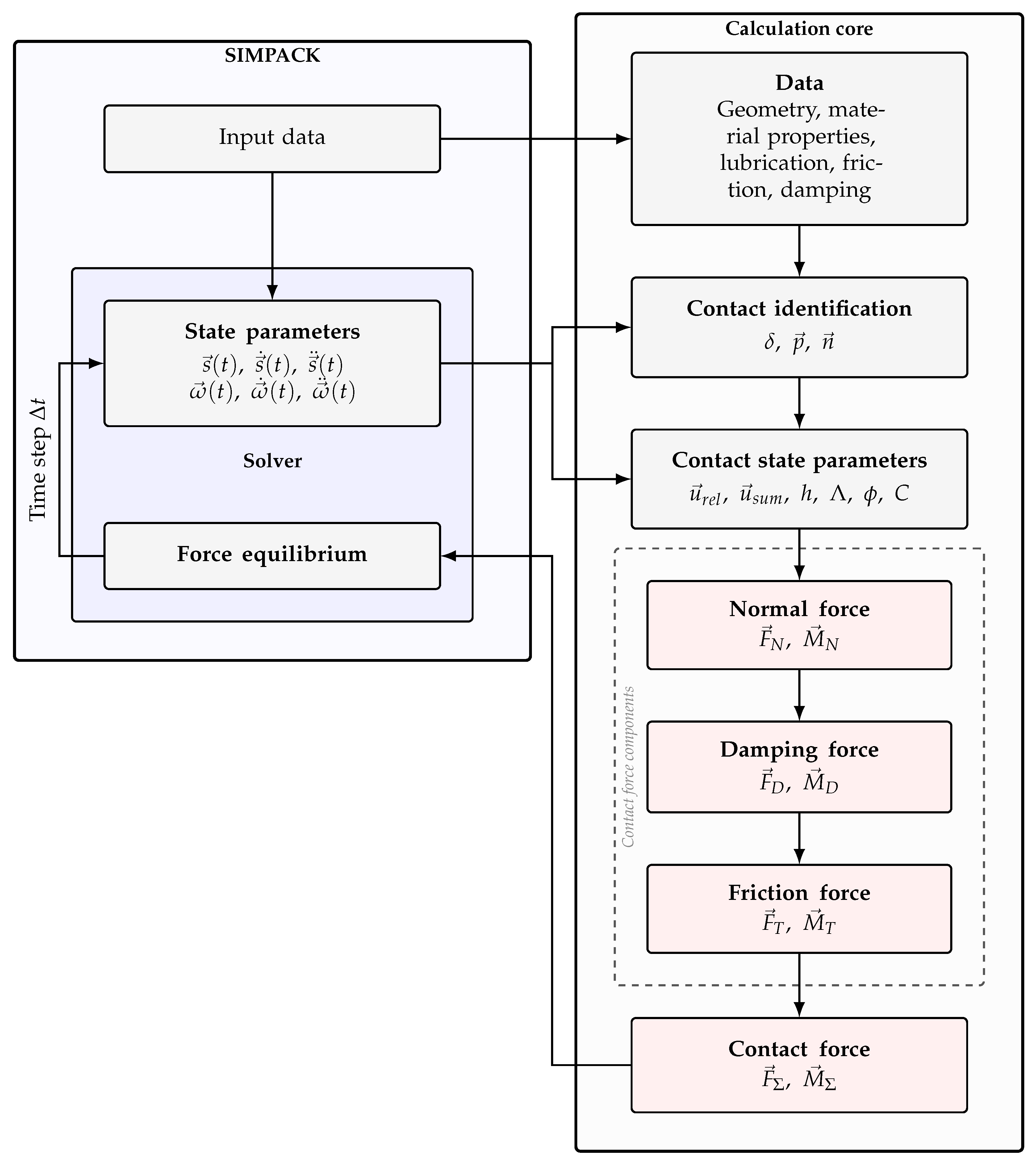
Figure 1 illustrates the computational workflow used to evaluate contact forces within the MBS model. At each time step Δ t , the solver provides the current state parameters, namely the relative position vector s → ( t ) , its velocity s → ˙ ( t ) , and acceleration s → ¨ ( t ) , as well as its angular equivalents ω → ( t ) , ω → ˙ ( t ) , and ω → ¨ ( t ) . Together with geometric data, material properties, lubrication parameters, friction coefficients, and damping constants, these values are passed to the calculation core.
Based on the current state, contact identification is performed. This yields the contact point p → , the contact normal vector n → , and the local penetration depth δ . Using a load–deformation relationship, the penetration δ is converted into the normal contact force F → N and the corresponding normal moment M → N [30].
In a subsequent step, the time-dependent contact state parameters are determined. These include the relative velocity at the contact points u → rel and the sum velocity u → sum , the lubricant film thickness h, the specific lubricant film parameter Λ , the solid load bearing ratio φ , and the electric capacitance C.
The normal force F → N , the kinematic quantities, and the lubricant properties are then used to evaluate the friction force F → T and the resulting friction moment M → T . The detailed formulation of the friction model is described in Section 2.2. The relative velocity u → rel is used to calculate the damping force F → D and the associated moment M → D (see Section 2.3).
Finally, the individual force contributions are superposed to obtain the total contact force
F → Σ = F → N + F → D + F → T
and the corresponding contact moment M → Σ . These quantities are returned to the Simpack MBS Solver, where they are used in the iterative solution of the force equilibrium for the next time step.

2.2. Contact Calculation

For the calculation of friction and the bearing’s electrical load capacitance, the contact force and the dimensions of the contact ellipse between the rolling element and the raceway are required. The contact is modeled as a point contact according to Hertz. The contact deformation and the semi-axes of the contact ellipse are calculated using the analytical approximations proposed by Hamrock and Brewe [74]. These formulations approximate the ellipticity parameter and the elliptical integrals as functions of the radii ratios of the contacting bodies [72]. The load–deformation relationship is described by Equation (1).
δ = F · 4.5 ϵ · R ′ · ( F N π · k · E ′ ) 2 3
The contact ellipse is characterized by the semi-axes a and b, given by Equations (2) and (3).
a = 6 · F N · k 2 · ϵ · R ′ π · E ′ 3
b = 6 · F N · ϵ · R ′ π · E ′ · k 3
The ellipse parameter k appearing in Equations (1)–(3) is estimated accordingly as a function of the radius ratio a H using the following relationship:
k = a H 2 / π
with
a H = R x R y , R x > R y R y R x , R x < R y
The calculation of the reduced radii R ′ is described by Equations (6)–(8).
1 R x = 1 R x 1 + 1 R x 2
1 R y = 1 R y 1 + 1 R y 2
1 R ′ = 1 R x + 1 R y
According to [74], the approximation of the elliptical integrals is given by the following equations:
F = π 2 + q H · ln a H
q H = π 2 − 1
ϵ = 1 + q H a H

2.3. Damping

According to Zeillinger [75], the damping effect of rolling bearings is largely determined by the contact points inside. The following factors significantly influence the damping behavior [75,76]:
  • Material damping (hysteresis) due to deformation and the imperfect elastic properties of the contacting surfaces.
  • Lubricating film damping in the entry zone and the inlet zone of the elastohydrodynamic contact between the rolling elements and the raceways.
Zeillinger also examined the dynamic behavior of the annular joint between the bearing outer ring and the housing. The joint was found to exhibit high damping capacity. However, when the joint clearance was small and the interfaces were lubricated, the resulting high stiffness limited relative motion between the contacting surfaces, preventing the damping mechanism from becoming effective, which is why this damping effect was disregarded. It is difficult to determine exact damping values. For this reason, parameter models are more commonly used in dynamic simulations. LaMBDA (Ver. 3.0) uses a parametric damping model adapted from Teutsch [72] that can be adjusted using two parameters ( δ max and d max ) to calculate the damping force in contact based on bearing element penetration.
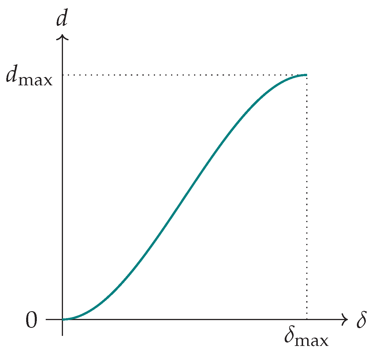
The roller raceway damping function calculates the damping coefficient d between these two boundary values using a continuous cubic function (see Figure 2). Here, v N is the penetration velocity along the contact normal vector. The damping force F D = − v N · d is then determined as follows [72]:
F D ( v N , δ max , d max ) = − v N · 0 , δ < 0 , f k ( δ max , d max , δ ) , 0 ≤ δ < δ max , d max , δ ≥ δ max .
This function f k , which depends on penetration δ , is uniquely determined by selecting the two parameters δ max , representing the penetration at maximum damping and d max , representing the maximum damping. The function also depends on the penetration velocity and is uniquely determined by the choice of the two parameters. The slope is zero for both δ = 0 and δ max .:
f k ( δ max , d max , δ ) = − 2 d max δ max 3 δ 3 + 3 d max δ max 2 δ 2
This damping model is used for both the integral and slice contact model because discretising the contact area does not affect the calculated damping force.

2.4. Friction Components

In EHL contact, the contact partners usually do not roll perfectly against each other, resulting in a superposition of rolling and sliding. Both forms of movement are counteracted by frictional forces. The total raceway friction force F T is described by Equation (14).
F T = − F roll ± F slide
The rolling friction F roll counteracts the rolling motion of the body and is caused by the compression of the fluid at the entry of the contact. Rolling friction can be calculated according to Crook [77] by solving the following integral for the contacting area.
F roll = 1 2 · ∫ x e x a h · l · d p d x d x
The portion from the load zone and the outlet contribute only slightly to the rolling resistance and are therefore neglected in [78]. The resulting sliding friction force F slide (see Equation (16)) can be decomposed into a solid-body sliding friction component F slide , s and a fluid sliding friction component F slide , f .
F slide = ψ · F slide , s + ( 1 − ψ ) · F slide , f
The weighting is taken into account by the asperity load ratio ψ , which describes the fraction of the total load carried by solid-body contacts.
ψ = F s F N
Here, F s describes the proportion of the normal force F N transmitted via the solid contacts [79]. The solid-body sliding friction force F s l i d e , s can be determined from the normal force acting in the contact and the solid-body friction coefficient μ , which is modeled as a function of the relative velocity between the rolling element and the raceway using the cubic approach proposed in [72].
F s l i d e , s = μ · F N
The sliding component in the lubricant builds up due to the shearing of the lubricant. Due to the low pressures in the inlet and outlet, the viscosity decreases, which is why the shear stress for these areas can be neglected and the main influence comes from the pressure directly acting in the contact [72]. The sliding component F slide , f is calculated according to Equation (19).
F slide , f = ∫ τ d A
For the calculation of the shear stress τ , the Ree–Eyring model is used, considering only the viscous component of the shear rate γ ˙ [80]. The viscous shear rate γ v ˙ depends on the Eyring shear stress τ e and the dynamic viscosity η and is given by the following equation:
γ ˙ v = τ e η sinh τ τ e
The Eyring shear stress represents the shear stress at which deviations from Newtonian behavior become significant [72]. Assuming a linear velocity distribution across the lubricant film thickness, the viscous component of the shear rate can be approximated by Equation (21) according to Lubenow [81].
γ v ˙ = v rel h cen
In Equation (21), v rel represents the relative sliding velocity of the contacting surfaces. The thermally corrected central lubricant film thickness h cen is given by the following equation:
h cen = Φ T , MuWi 75 · h cen , iso
The isothermal central film thickness h cen , iso (given in Equation (22)) is calculated using the approximation proposed by Chittenden et al., who distinguish between the radii in the direction of the flow and transverse to it, thereby accounting for arbitrary lubricant entrainment directions. Since this formulation assumes isothermal conditions within the contact zone, thermal effects are incorporated through the thermal correction factor Φ T , MuWi 75 proposed by Murch and Wilson in [82] (Equation (23)).
Φ T , MuWi 75 = 3.94 3.94 + L 0.62
The thermal load parameter L is definied as
L = η 0 · β · u m 2 λ F = − ∂ η ∂ T · u 2 λ F
where η 0 is the dynamic viscosity at transmission pressure, u m the mean entrainment velocity, λ F the thermal conductivity of the oil, and β the temperature coefficient. The calculation of h cen , iso in Equation (25) is based on the dimensionless parameters introduced by Dowson and Higginson, as listed in Table 2.
h cen , iso = 4.31 · R ′ · G 0.49 · U 0.67 · W − 0.073 · 1 − exp − 1.23 · R s R e 2 3
R s R e = R y R x · c o s 2 ξ + s i n 2 ξ c o s 2 ξ + R y R x · s i n 2 ξ
Table 2. Dimensionless parameters for film thickness calculation.
-Equation
Velocity parameter
U = η 0 · v ∑ E ′ · R e ′
Load parameter
W = F N E ′ · R e ′ 2
Material parameter
G = α p · E ′

Cage Contact

The total frictional torque is only slightly affected by the friction between the rolling elements and the cage. The friction force F T , C acting at the contact is modelled as
F T , Cage = μ c · F N , C
where F N , C denotes normal load between the rolling elements and the cage and μ c the coefficient of friction, modeled as a function of the relative velocity between the rolling element and the cage according to the cubic approach from [72].

3. Electrical Capacitance

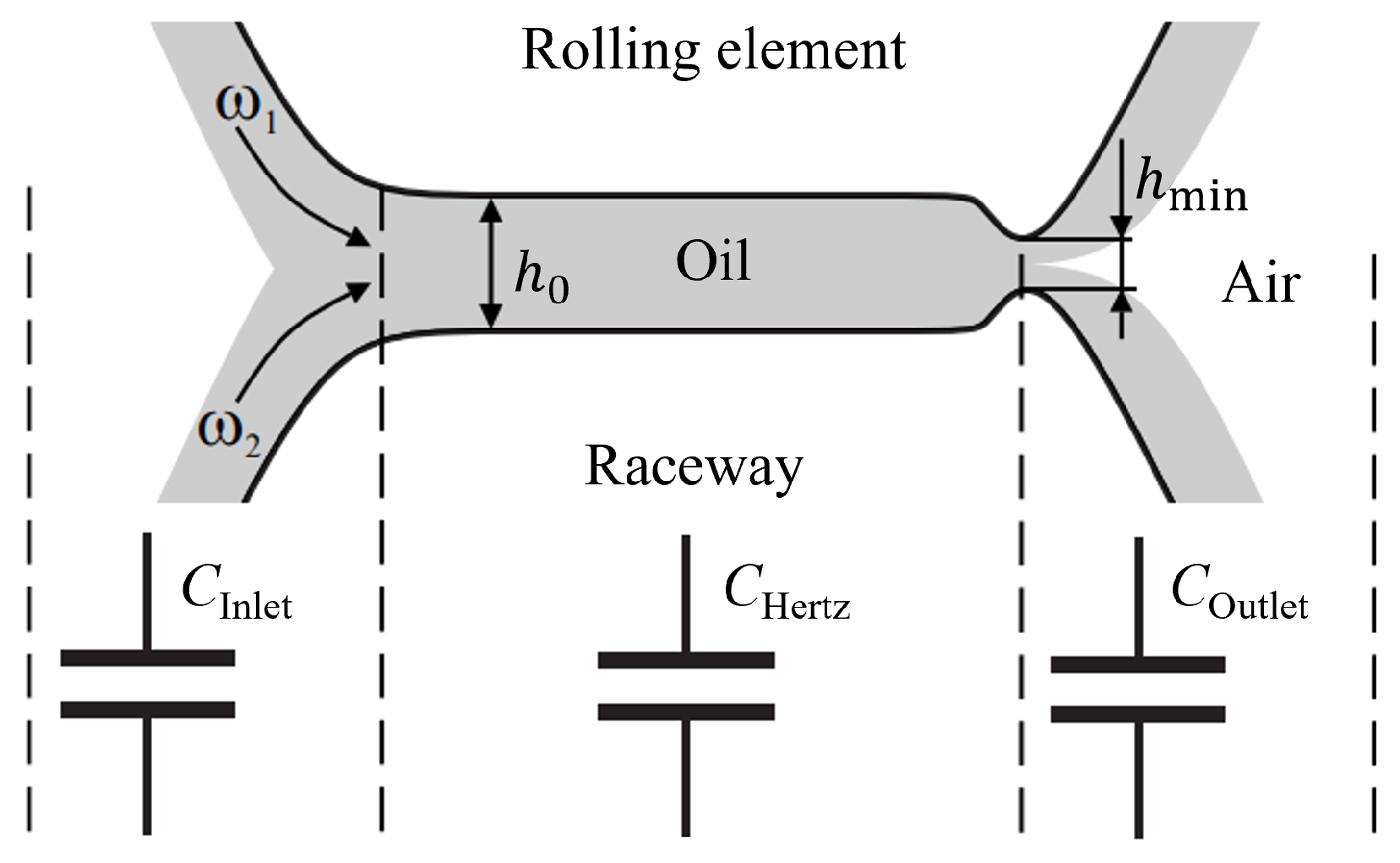
In this work, the bearing capacitance is calculated based on the contact capacitance. The conversion of an elastohydrodynamic lubricated contact to a capacitive network is depicted in Figure 3. The contact is divided into three different regions, each of which is assigned a capacitance: the capacitance of the Hertzian area C Hertz , the capacitance of the inlet region C Inlet , and the capacitance of the outlet region C Outlet .
The three different capacitance are assumed to be in parallel. Therefore, the overall contact capacitance C Con can be calculated according to Equation (31).
C Con = C Inlet + C Hertz + C Outlet
The Hertzian contact area is commonly regarded as a plate capacitor. Under this assumption, its capacitance C Hertz can be calculated by Equation (32)
C Hertz = ϵ 0 · ϵ r · A Hertz h cen
where the Hertzian contact area A Hertz is the plate area of the capacitor and the central gap height h cen is its plate distance. The permittivity of this model capacitor ϵ 0 · ϵ r consists of the permittivity of vacuum ϵ 0 and the relative permittivity of the lubricant ϵ r , which acts as a dielectric.
Equation (32) assumes the surfaces of the rolling element and the raceway to be in parallel. This approximation is not valid for the inlet and the outlet zone. The capacitance of these regions can be determined numerically [68], semi-analytically [70], or analytically by using a correction factor k c that is applied to C Hertz . The correction factor k c is defined by the ratio between the overall contact capacitance C Con and the capacitance of the Hertzian contact area:
k c = C Inlet + C Hertz + C Outlet C Hertz = C Con C Hertz
With knowledge of k c , C Con can be approximated fully analytically based on C Hertz using Equation (32). The correction factor method is therefore well suited for a quick approximation of contact capacitance but has lower accuracy compared to more complex calculation methods [69,83]. This is why there are several empirically determined estimates for k c , including constant factors [84] or linear equations as a function of h cen [65,85,86]. A more recent approach was published by [67] and calculates k c using the dimensionless factors by Hamrock and Dowson [87]:
k c = 9.5923 · U 0.3305 · G 0.3431 · W − 0.3342 · k e 0.1391
It was derived based on numerical calculations of the contact capacitance of radial deep-groove ball bearing and directly takes into account the operating conditions.
Due to its simplicity, the correction factor method is easy to implement into existing contact simulations. Therefore, it is applied in this work for the calculation of C Con . In the first step, the capacitance of the Hertzian contact area C Hertz is determined based on the previously calculated contact properties. For this purpose, the discrete elements of the contact simulation are regarded as small plate capacitors that are connected in parallel. The plate area of each capacitor is given by the size of the discrete element. The plate distance is given by the local gap height value. In this way, the minimum gap height can be considered in the capacitance calculation. The relative permittivity of each small capacitor is calculated by Bode’s equation (given in Equations (35)–(37)) in dependency of the inlet temperature of the oil and the local pressure inside the small capacitor.
ϵ r ( p , T ) = ϵ r T + k 3 · ( ρ ( p , T ) − ρ T ( T ) )
where ϵ r T is the temperature-dependent relative permittivity given by
ϵ r T = k 1 · β ( T ) − 1 2 · ρ T ( T ) 1 6 + k 2 · T
and β ( T ) is the isothermal compressibility
β ( T ) = − 1 V d V d p = a 1 a 2 + a 3 · T + a 4 · T 2 + a 5 · T 3
The parameters k 1 , k 2 , and k 3 are characteristic values of the lubricant that were experimentally determined. In this way, the capacitance C Hertz is determined taking into account local pressure changes and their effect on permittivity. The surrounding capacitance [88] of the bearing is included in the applied approach. The focus is on contact capacitance, as the dynamic effects examined via the multibody simulation affect the contact area.

4. Results and Discussion

In the following, the simulation results are presented and discussed. First, the friction torque is used as a validation quantity for the model implementation. Subsequently, the capability of the fully dynamic model to predict cage instability under axial excitation is examined. Finally, the applicability of the LaMBDA tool to the calculation of the Hertzian contact capacitance is demonstrated.

4.1. Friction Torque

For validation purposes, the friction torque has proven to be a particularly suitable resultant quantity. It directly arises from the shear stresses in the bearing contacts. This allows a comprehensive comparison with established state-of-the-art methods used in both academia and industry. The SKF catalogue method is an analytical model, based on empirically fitted formulas and averaged operating conditions. FVA-Workbench by FVA (Forschungsvereinigung Antriebstechnik e.V., Frankfurt, Germany) and Bearinx by Schaeffler are quasi-static simulation tools, which resolve load distribution and contact conditions under steady-state assumptions.
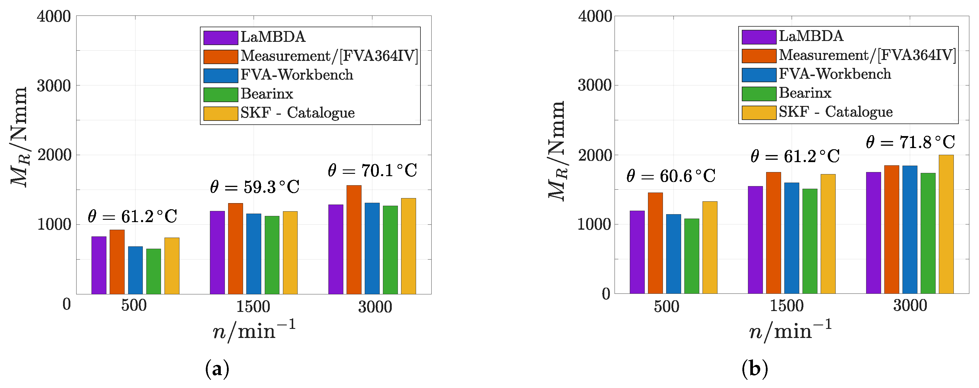
Figure 4a presents a comparison of the friction moment ( M R ) of a 6319 deep-groove ball bearing subjected to a radial load ratio of ( C / P = 10 ) for three operating speeds of 500 min−1, 1500min−1 and 3000 min−1. The geometry data of the bearing are given in Table 3.
The results obtained with the proposed multibody simulation tool LaMBDA (purple) are compared against experimental friction torque measurements from the FVA Project 364 IV (red) [89], as well as against established quasi-static calculation approaches, namely the FVA Workbench, (Ver. 11.0) (blue), BearinX (Ver. 2026) by Schaeffler (green), and the catalogue-based method published by SKF (yellow). The detailed results are given in Table 4.
The experimental bearing test series was lubricated using the ISO VG 100 mineral oil FVA3A, a reference oil with additives. The oil level was adjusted to half the height of the lowest rolling element, in accordance with the lubrication specifications reported for FVA3A [89]. The measured oil bath temperature θ was explicitly considered in all simulation and calculation methods to ensure a consistent thermal boundary condition.
A corresponding set of experiments and simulations was conducted for a higher radial load ratio of C / P = 6.5 . The results of this second load case are shown in Figure 4b, enabling an assessment of the influence of load level and lubricant formulation on the predicted friction behavior. The total friction torque increases with rising radial load due to changes in the contact conditions, as described by Hertzian contact theory. As the load increases from C / P = 10 to C / P = 6.5 , the elliptical contact area between the rolling elements expands. This leads to an expansion of local relative speed within the contact. Due to elastic deformation and kinematic constraints in the rolling contact, differential slip occurs and is distributed over the contact area. As the contact size increases, the regions experiencing micro-slip grow, resulting in higher friction force and, consequently, increased total friction torque. Furthermore, the contact is of point type, in contrast to line contact. Owing to the doubly curved geometry of the contacting bodies, point contacts inherently exhibit higher slip gradients and greater local relative velocities. As a result, differential slip is more pronounced than in line contacts, further contributing to the increase in friction torque. All this leads to an increasing total friction torque of 57.4% at 500 min−1 for the measurements, when increasing the radial load from C / P = 10 to C / P = 6.5 . LaMBDA gives a total friction torque difference of 44.0%.
For both load cases, all approaches exhibit a clear and monotonic increase in friction torque with increasing rotational speed (e.g., the total friction torque increases by 69.1% from 500 min−1 to 3000 min−1 for the measurements and 55.2% for LaMBDA). This trend reflects the growing contribution of lubricant shear losses, rolling–sliding effects in the contacts, and churning losses at higher speeds. Across the investigated speed range, most numerical and analytical methods tend to underestimate the experimentally measured friction torques, with the deviation generally increasing at higher rotational speeds. It should be noted, however, that no information on measurement scatter or standard deviation is provided in the FVA 364 IV dataset, which limits a quantitative assessment of the statistical significance of these deviations.
For the quasi-static load case, all models show good agreement between the calculated and experimental results. This demonstrates that the quality of the developed LaMBDA model is at a comparable level to that of the other models. The main advantage of the approach presented here lies in its coupling with the MBS. The following section therefore describes a load case investigating the dynamic behaviour of the roller speed when excited in axial direction. Load cases like this can only be investigated by multibody simulations.

4.2. Roller Speed Instability

While friction torque is a useful validation quantity, it can also be predicted with established quasi-static approaches. In contrast, a central motivation for employing a fully dynamic multibody model is the prediction of stability limits of the bearing kinematics under external excitation. Deep-groove ball bearings may exhibit a transition from a stable running state to an altered, more unstable regime when the system is subjected to axial vibration. Such transitions are governed by the interplay of excitation frequency, excitation amplitude, and static load and are directly linked to changes in roller kinematics as well as to intermittent contacts outside the nominal load zone. These phenomena are inherently time dependent. They cannot be captured by quasi-static load distribution methods.
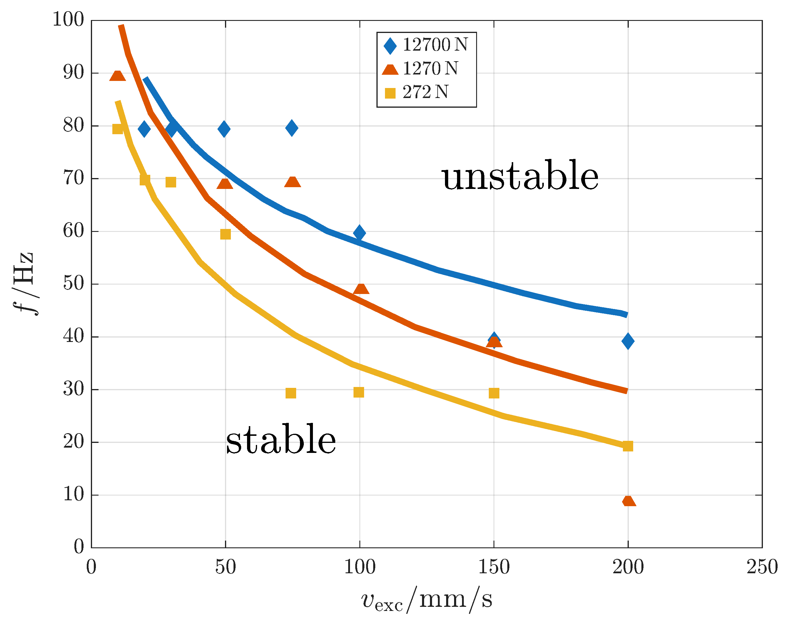
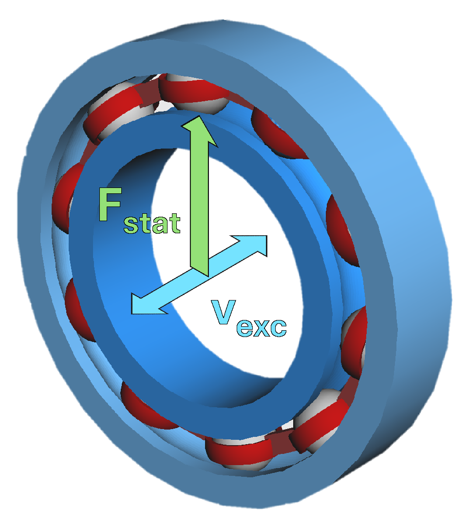
To demonstrate this use case, Figure 5 summarizes an experimentally and numerically derived instability boundary for a 6220 deep-groove ball bearing under axial system excitation from the FVA project 589 I [90]. The diagram maps the onset of an altered (unstable) running behavior by the excitation frequency f and the excitation speed v exc for three different static radial loads F stat . Here, v exc denotes the vibration velocity amplitude of the imposed harmonic axial displacement of the bearing system. The acceleration of the excitation speed directly determines the inertial forces acting on the raceways and the rollers, which are critical for the stability of the internal bearing kinematics. Figure 6 shows the operation conditions for this bearing.
Two characteristic trends are evident. Firstly, the instability boundary exhibits monotonic decay: comparatively high excitation frequencies are required to trigger the transition at low excitation speeds (small vibration amplitudes), whereas instability already occurs at substantially lower frequencies at high excitation speeds. This behaviour suggests that the governing parameter is related to acceleration during excitation rather than to a single resonant frequency. Accordingly, the boundary shows a continuous course without pronounced peaks, which would otherwise suggest resonance-dominated amplification.
Secondly, increasing the static load shifts the instability boundary towards higher excitation levels. For the highest static load, substantially higher combinations of f and v exc are needed to disturb the bearing motion compared to the lightly loaded case. Physically, a higher static load increases the confinement of rollers within the load zone. Conversely, under sufficiently large excitation accelerations, additional contact forces can occur outside the nominal load zone, keeping the rolling elements closer to their kinematic speeds around the circumference. In this regime, the change in the distribution of rolling element speeds is significant, which constitutes a relevant stability concern.

4.3. Capacitance

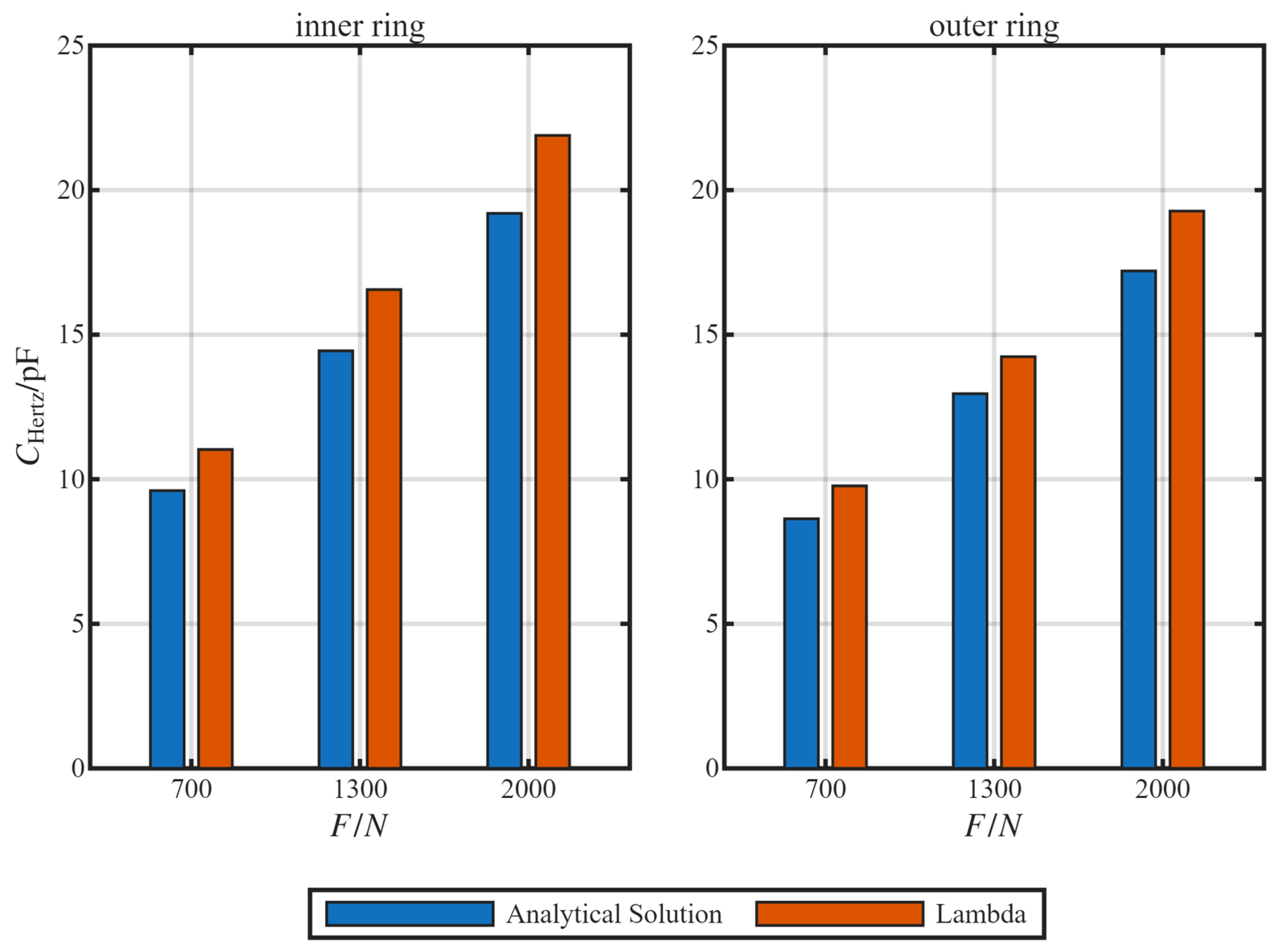
The tool LaMBDA is not limited to the calculation of bearing friction. Furthermore, it can be used to calculate the capacitance of the Hertzian contact area. This is depicted in Figure 7 for a pure axially loaded DGBB 6208. As under pure axial load, all of the rolling elements are equally loaded, equal contact condition and therefore equal contact capacitances are generated. Figure 7 therefore gives the capacitance C Hertz of the Hertzian contact area for a single rolling element for both the inner ring contact and the outer ring contact. Three different axial loads are investigated (700 N, 1300 N, 2000 N) at constant rotating speed (2750 rpm) and constant oil temperature (40 °C). The calculation is carried out for a mineral oil. Table 5 gives the parameters to calculate the oils’ permittivity according to Equation (35). The geometry data of the bearing is given in Table 6.
One of the major benefits of LaMBDA is the advanced calcuation of bearing kinematics. Therefore, the capacitance values calculated by LaMBDA are compared to capacitance values calculated using an analytical method. For this comparison, the hydrodynamic speed of the roller contacts was calculated solely based on the bearing geometry. The mathematical description of the hydrodynamic speed is given in [84]. As the calculation is based on geometrical relations inside the bearing, it gives equal hydrodynamic speed for each contact. With help of the hydrodynamic speed, the central gap height is calculated according to Chittenden et al. [91]. The Hertzian contact area A Hertz = π a b of both contacts is calculated based on the mechanical load on the rolling element using Equations (2) and (3). The relative permittivity is calculated for the Hertz pressure p 0 . Subsequently, the capacitance values to compare with the results of LaMBDA are calculated using Equation (32).
As depicted in Figure 7, the contact capacitances in both models are in the same order of magnitude. At the inner contacts, the capacitance values by LaMBDA are around 14% higher compared to the analytical method; at the outer ring, the deviation is in the range of 10% to 13%. The contact capacitance rises with rising axial load according to both calculations. This is due to the enlargement of the Hertzian contact, which overweighs the lowering of the gap height. A rise of axial load from 700 N to 2000 N leads to a reduction of 9% in gap height, while the contact area increases by 78%. The capacitances of the outer ring contacts are generally lower than the capacitances of the corresponding inner ring contacts. Due to the radii ratios of ball and raceway, the outer ring contacts can build about 20% higher lubricating films and about 10% larger contact areas compared to the inner ring contacts. In combination, the effects lead to 10% to 14% lower contact capacitance. Compared to the analytical calculation method, LaMBDA gives higher contact capacitances for all investigated loads. The main difference between the two models is the consideration of dynamic effects in LaMBDA. They lead to lower gap heights due to shear thinning of the oil or heating due to the high pressure. These lower gap heights lead to a rise of contact capacitance. The results show that LaMBDA is capable of calculating the capacitance of the Hertzian contact area. Furthermore, it can consider complex bearing dynamics in the lubricating film formation and their effect on contact capacitance.

5. Conclusions

The presented friction model for deep-groove ball bearings demonstrates very good agreement with measured friction torques and accurately captures the experimentally observed trends under varying operating conditions. Owing to its fully dynamic formulation, the model enables a time-dependent evaluation of the bearing kinematics, allowing transient effects and changes in the motion of individual rolling elements to be resolved in detail.
Beyond friction prediction, the model provides access to phenomena that cannot be addressed by quasi-static approaches. In particular, it allows the prediction of roller speed instability limits under axial excitation, where changes in roller kinematics govern the transition from stable to instable conditions. Furthermore, the implemented framework enables the calculation of Hertzian contact capacitances, thereby extending the applicability of the model to electro-tribological analyses of rolling bearings under transient conditions.
Despite these positive results, the current model still exhibits limitations that should be addressed in future work. In particular, the systematic inclusion of churning and drag losses is required, as these effects influence rolling element kinematics and, consequently, local contact friction. In existing engineering approaches, churning and drag losses are typically described using empirical catalogue methods provided by bearing manufacturers. For example, the Schaeffler catalogue provides in [6] equations for load-independent losses in terms of the friction torque M 0 :
M 0 = f 0 · 10 − 7 · d m 3 · ( ν · n ) 2 3 , for ν · n ≥ 2000 mm 2 / ( s min )
M 0 = 160 · 10 − 7 · f 0 · d m 3 , for ν · n < 2000 mm 2 / ( s min )
These equations include churning and drag losses. However, rolling resistance is also contained in M 0 and needs to be separated, as rolling resistance is already considered within the contact friction forces and is inherently load dependent. The SKF approach directly provides a formulation for the churning and drag losses in ball bearings in terms of a drag torque:
M drag = V M · K Ball · d m 5 · n 2
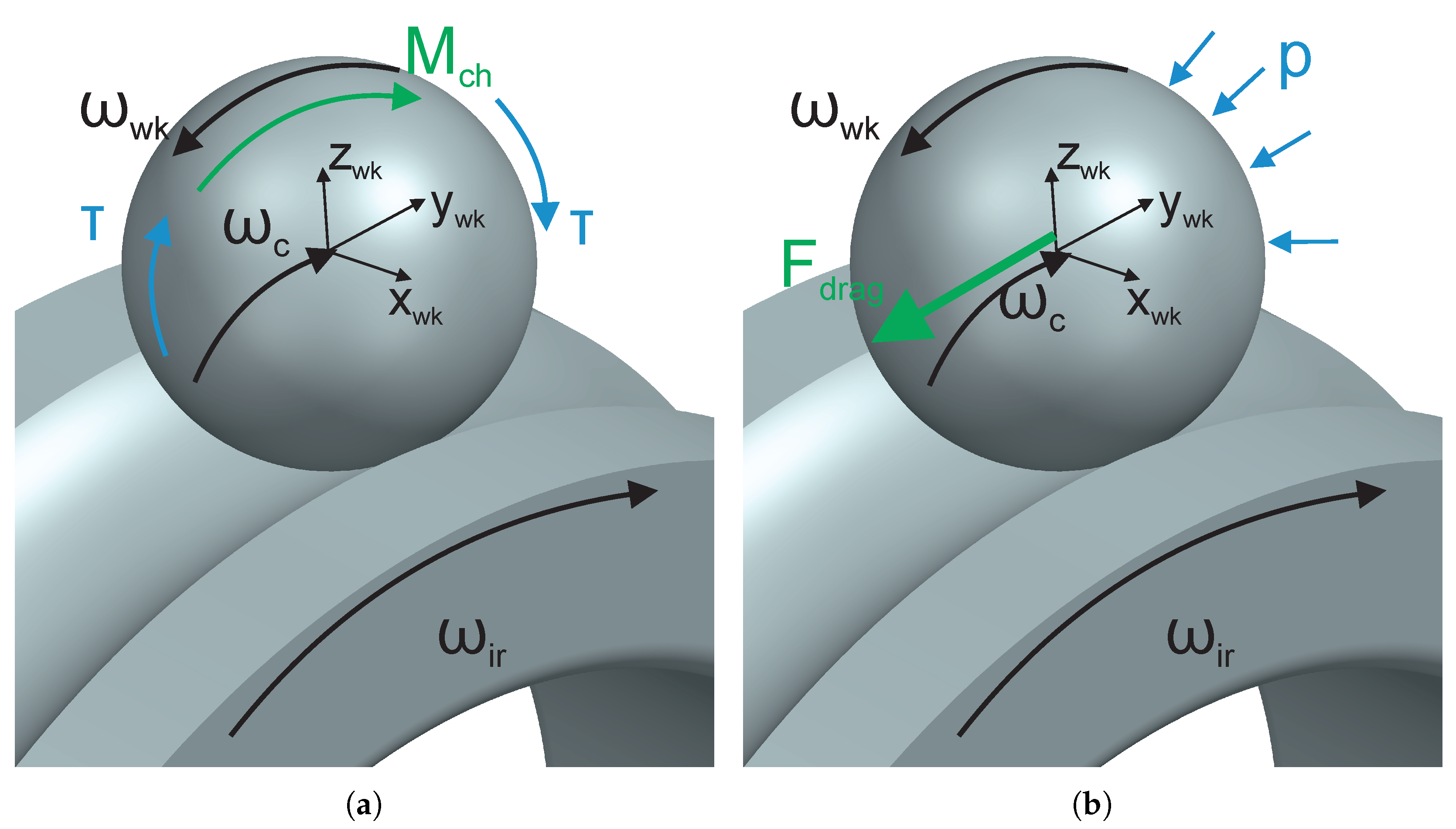
where V M and K Ball are determined from tabulated values given in [92]. The resulting drag torque is defined with respect to the entire bearing. However, these approaches describe the losses on a global bearing level. A more detailed description requires the allocation of churning losses to individual rolling elements. Churning acts in the form of a resisting moment M ch on the rolling elements (see Figure 8a), while drag results in hydrodynamic force F drag acting on the rolling elements (see Figure 8b). This allows the influence of fluid-induced forces on the rolling element kinematics to be considered. The resulting changes in kinematics affect the behaviour in the acceleration zones and thereby influence the contribution to the friction torque.
In summary, the presented model provides a solid and versatile basis for the analysis of friction behaviour and dynamic stability in deep-groove ball bearings. Its dynamic nature enables the investigation of time-dependent effects and offers the potential for the early prediction of critical operating conditions, including smearing-related damage mechanisms.

Author Contributions

Conceptualization, S.S. and K.M.B.; methodology, S.S. and K.M.B.; software, S.S.; formal analysis, S.S., K.M.B., and S.P.; investigation, S.S., K.M.B., and S.P.; resources, O.K.; data curation, S.S., K.M.B., and S.P.; writing—original draft preparation, S.S., K.M.B., and S.P.; writing—review and editing, S.S., K.M.B., S.P., and S.G.; visualization, S.S., K.M.B., and S.P. All authors have read and agreed to the published version of the manuscript.

Funding

This research was funded by Forschungsvereinigung Antriebstechnik (FVA) e.V., FVA project number 625 I.

Data Availability Statement

Data are available on request from the authors.

Conflicts of Interest

The authors declare no conflicts of interest.

Nomenclature

aLarge half-axis of the Hertzian contact
a i Viscosity parameter
AContact area
bSmall half-axis of the Hertzian contact
b i Viscosity parameter
BViscosity parameter
CViscosity parameter
C Hertz Capacitance of the Hertzian area
C Inlet Capacitance of the inlet region
C Outlet Capacitance of the outlet region
C u Fatigue load limit, radial
C 0 r Basic static load rating, radial
C r Basic dynamic load rating, radial
dBore diameter
DOutside diameter
d max Maximum damping coefficient
d m Mean bearing diameter
E i ′ Reduced Young’s modulus
fExcitation frequency
f 0 Bearing factor for frictional torque
F D Damping force
F drag Drag Force
F N Normal load force
F R Traction force
F roll Roll traction force
F S Asperity load
F Slide Slide traction force
F Slide , f Fluid slide traction force
F Slide , s Solid slide traction force
F stat Static load
GMaterial parameter
hFilm height
h cen Central lubricant height
h iso Isothermal central lubricant height
KViscosity parameter
lLine-contact length
M 0 Load-independent friction torque
M c h Churning torque
pPressure
p max Maximum pressure
R x 1 , y 1 , R x 2 , y 2 Radius
R ′ Reduced radius
TTemperature
UVelocity parameter
v ∑ Sum velocity
v exc Excitation speed
v N Penetration velocity in normal direction
WLoad parameter
w ir Angular velocity of the inner ring
w wk Angular velocity of the rolling element
w c Angular velocity of the cage
xRolling-direction coordinate
x a Beginning of contact
x e End of contact
α p Pressure-viscosity coefficient
β Viscosity-temperature coefficient
γ ˙ Shear rate
δ Penetration depth
δ max Penetration depth at maximum damping
ϵ 0 Permittivity of vacuum
ϵ r Relative permittivity
η Viscosity
η 0 Base viscosity
λ F Thermal conductivity
ν i Poisson’s ratio
ν 40 Kinematic viscosity at 40°C
ρ Density
τ Shear stress
Φ T , M u W i 75 Correction factor
ψ Asperity load ratio
Ψ i Solid contact Ratio
TTemperature

References

  1. Bakolas, V.; Roedel, P.; Koch, O.; Pausch, M. A First Approximation of the Global Energy Consumption of Ball Bearings. Tribol. Trans. 2021, 64, 883–890. [Google Scholar] [CrossRef] [Scilit]
  2. Arora, A.; Jha, S.; Saini, V. Aspects of green-sustainable tribology and its impacts on future product development: A review. Ecol. Environ. Conserv. 2019, 25, S146–S157. [Google Scholar]
  3. Höhn, B.; Michaelis, K.; Hinterstoißer, M. Optimization of Gearbox Efficiency. Eng. Mater. Sci. 2009, 48, 441–461. [Google Scholar]
  4. Fernandes, C.M. Power Loss in Rolling Bearings and Gears Lubricated with Wind Turbine Gear Oils. Ph.D. Thesis, Universidade do Porto, Porto, Portugal, 2015. [Google Scholar]
  5. Hua, X.; Gandee, E. Vibration and dynamics analysis of electric vehicle drivetrains. J. Low Freq. Noise Vib. Act. Control 2021, 40, 1241–1251. [Google Scholar] [CrossRef] [Scilit]
  6. Schaeffler Technologies AG & Co. KG. (Ed.) Wälzlagerpraxis: Handbuch zur Gestaltung und Berechnung von Wälzlagerungen, 4th ed.; Vereinigte Fachverlage: Mainz, Germany, 2015. [Google Scholar]
  7. Liebrecht, J.; Si, X.; Sauer, B.; Schwarze, H. Investigation of Drag and Churning Losses on Tapered Roller Bearings. Stroj. Vestn.-J. Mech. Eng. 2015, 61, 399–408. [Google Scholar] [CrossRef] [Scilit]
  8. Wang, Y.; Lin, F.; Jiang, H.; Yuan, W. Investigation on frictional characteristic of deep-groove ball bearings subjected to radial loads. Adv. Mech. Eng. 2015, 7, 1687814015586111. [Google Scholar] [CrossRef] [Scilit]
  9. Kanatsu, M.; Ohta, H. Running Torque of Ball Bearings With Polymer Lubricant (Running Torque Formulas of Deep Groove Ball Bearings Under Axial Loads). J. Tribol. 2008, 130, 041507. [Google Scholar] [CrossRef] [Scilit]
  10. Kumar, H.; Gupta, V.; Bharath, V.; Tiwari, M.; Paul, S.K.; Agrawal, L.; Singh, A.P.; Jain, A. Effect of Surface Roughness on the Friction Moment in a Lubricated Deep Groove Ball Bearing. Lubricants 2024, 12, 443. [Google Scholar] [CrossRef] [Scilit]
  11. Huo, Z.; Chen, J.; Hao, L.; Gao, J. Study on the Effect of Starved Lubrication on the Dynamic Characteristics of Locally Failed Roller Bearings. Tribol. Trans. 2024, 67, 952–961. [Google Scholar] [CrossRef] [Scilit]
  12. Vidyasagar, K.E.C.; Pandey, R.K.; Kalyanasundaram, D. An exploration of frictional and vibrational behaviors of textured deep groove ball bearing in the vicinity of requisite minimum load. Friction 2021, 9, 1749–1765. [Google Scholar] [CrossRef] [Scilit]
  13. Petrzik, T.C.; Brill, K.M.; Jacobs, G.; Koch, O.; Lehmann, B.; Rößler, P.; Niazmehr, A. Numerical and Experimental Investigation of Different Oil Levels and Operation Conditions on the Individual Hydraulic Losses of Spherical Rolling Bearings. Lubricants 2026, 14, 16. [Google Scholar] [CrossRef] [Scilit]
  14. Wingertszahn, P.; Koch, O.; Maccioni, L.; Concli, F.; Sauer, B. Predicting Friction of Tapered Roller Bearings with Detailed Multi-Body Simulation Models. Lubricants 2023, 11, 369. [Google Scholar] [CrossRef] [Scilit]
  15. Takahashi, K.; Suzuki, D.; Nagatomo, T. Effect of Axial Clearance on Rolling Element Load of Double Row Tapered Roller Bearings. Q. Rep. RTRI 2019, 60, 196–201. [Google Scholar] [CrossRef] [Scilit] [PubMed]
  16. Xu, T.; Yang, L.; Wu, Y. Friction torque study on double-row tapered roller bearing. In Proceedings of the 2019 IEEE International Instrumentation and Measurement Technology Conference (I2MTC), Auckland, New Zealand, 20–23 May 2019; pp. 1–6. [Google Scholar] [CrossRef] [Scilit]
  17. Jones, A.B. A General Theory for Elastically Constrained Ball and Radial Roller Bearings under Arbitrary Load and Speed Conditions. J. Basic Eng. 1960, 82, 309–320. [Google Scholar] [CrossRef] [Scilit] [PubMed]
  18. Palmgren, A. Ball and Roller Bearing Engineering; SKF Industries Inc.: Gothenburg, Sweden, 1959. [Google Scholar]
  19. Sjovall, H. The Load Distribution within Ball and Roller Bearings under Given External Radial and Axial Loads. Tek. Tidskr. Mek. 1933, 9, 97–102. [Google Scholar]
  20. Bajer, P. Einflussgrößen auf das Schlupfverhalten von Wälzlagern in Generatorgetrieben. Ph.D. Thesis, Technische Universität Kaiserslautern, Kaiserslautern, Germany, 2016. [Google Scholar]
  21. van Lier, H. Neuhärtungsgefährdung von Radial-Zylinderrollenlagern durch Lastaufschaltungen in Betriebspunkten mit Käfigschlupf. Ph.D. Thesis, Rheinisch-Westfälische Technische Universität Aachen, Aachen, Germany, 2015. [Google Scholar]
  22. Boness, R.J. Cage and Roller Slip in High-Speed Roller Bearings. J. Mech. Eng. Sci. 1969, 11, 181–188. [Google Scholar] [CrossRef] [Scilit]
  23. Yilmaz, M.; Lohner, T.; Stahl, K. Gear and bearing power losses under minimum quantity lubrication. Ind. Lubr. Tribol. 2022, 74, 985–994. [Google Scholar]
  24. Hu, L.; Li, W.; Li, B.; Cui, B.; Wang, Z.; Wang, Y. Wear characteristics and mechanism evaluation of high-speed petal magnetic rotor series bearings (HPMRSBs) in vacuum. Compos. Part B Eng. 2026, 313, 113369. [Google Scholar] [CrossRef] [Scilit]
  25. Palmgren, A.G. Die Lebensdauer von Kugellagern (Life Length of Roller Bearings or Durability of Ball Bearings). Z. Vereines Dtsch. Ingenieure 1924, 14, 339–341. [Google Scholar]
  26. Hong, S.H.; Tong, V.C. Rolling-Element Bearing Modeling: A Review. Int. J. Precis. Eng. Manuf. 2016, 17, 1729–1749. [Google Scholar] [CrossRef] [Scilit]
  27. Dowson, D.; Higginson, G.R. Elasto-Hydrodynamic Lubrication, 4th ed.; Pergamon Press: Oxford, UK, 1977; pp. 161–181. [Google Scholar]
  28. Jiang, Z.; Huang, X.; Zhu, H.; Jiang, R.; Du, S. A new method for contact characteristic analysis of the tapered roller bearing in wind turbine main shaft. Eng. Fail. Anal. 2022, 141, 106729. [Google Scholar] [CrossRef] [Scilit]
  29. Zander, M.; Otto, M.; Lohner, T.; Stahl, K. Evaluation of friction calculation methods for rolling bearings. Forsch. Ingenieurwesen 2023, 87, 1307–1316. [Google Scholar] [CrossRef] [Scilit]
  30. Kiekbusch, T. Strategien zur Dynamischen Simulation von Wälzlagern. Ph.D. Thesis, TU Kaiserslautern, Kaiserslautern, Germany, 2017. Maschinenelemente und Getriebetechnik Berichte Bd. 23/2017. [Google Scholar]
  31. Qian, W. Dynamic Simulation of Cylindrical Roller Bearings—Dynamische Simulation von Zylinderrollenlagern. Ph.D. Thesis, RWTH Aachen, Aachen, Germany, 2014. [Google Scholar]
  32. Qi, Z.; Wang, G.; Zhang, Z. Contact Analysis of Deep Groove Ball Bearings in Multibody Systems. Multibody Syst. Dyn. 2015, 33, 115–141. [Google Scholar] [CrossRef] [Scilit]
  33. Lacroix, S.; Nélias, D.; Leblanc, A. Four-Point Contact Ball Bearing Model with Deformable Rings. J. Tribol. 2013, 135, 031402. [Google Scholar] [CrossRef] [Scilit]
  34. Jin, K.F.; Yao, T.Q. Multi-Body Contact Dynamics Analysis of Angular Contact Ball Bearing. Appl. Mech. Mater. 2013, 444–445, 45–49. [Google Scholar] [CrossRef]
  35. Liu, X.; Deng, S.; Teng, H. Dynamic Stability Analysis of Cages in High-Speed Oil-Lubricated Angular Contact Ball Bearings. Trans. Tianjin Univ. 2011, 17, 20–27. [Google Scholar] [CrossRef] [Scilit]
  36. Gismeros Moreno, R.; Marques, F.; Corral Abad, E.; Meneses Alonso, J.; Flores, P.; Castejon, C. Enhanced modelling of planar radial-loaded deep groove ball bearings with smooth-contact formulation. Multibody Syst. Dyn. 2024, 60, 121–159. [Google Scholar] [CrossRef] [Scilit]
  37. Stacke, L.E.; Fritzson, D.; Nordling, P. BEAST—A Rolling Bearing Simulation Tool. Proc. Inst. Mech. Eng. Part K J. Multi-Body Dyn. 1999, 213, 63–71. [Google Scholar] [CrossRef] [Scilit]
  38. Stacke, L.E.; Fritzson, D. Simulation of Rolling Element Bearings; SKF Nova AB: Gothenburg, Sweden, 1999. [Google Scholar]
  39. Stacke, L.E.; Fritzson, D. Dynamic Behavior of Rolling Bearings: Simulations and Experiments. Proc. Inst. Mech. Eng. Part J J. Eng. Tribol. 2001, 215, 499–508. [Google Scholar] [CrossRef] [Scilit]
  40. Ioannides, E.; Stacke, L.E.; Fritzson, D.; Nakhimovski, I. Multibody Rolling Bearing Calculations: Computer Program BEAST. In Proceedings of the World Tribology Congress III (WTC 2005), Washington, DC, USA, 12–16 September 2005; pp. 903–904. [Google Scholar] [CrossRef] [Scilit]
  41. Aramaki, H. Rolling Bearing Analysis Program Package BRAIN. Motion Control 1997, 3, 15–24. [Google Scholar]
  42. Aramaki, H.; Nakano, Y.; Shoda, Y. Rolling Bearing Analysis Codes BRAIN—The Estimation of Rolling Bearing Performance for an Automotive Application; SAE International Congress and Exposition: Warrendale, PA, USA, 1997. [Google Scholar]
  43. Hahn, B.; Smolenski, M.; Neukirchner, J. Investigations of New Cage Designs for the Main Bearings in Multi-Megawatt Wind Power Plants. In Proceedings of the 2nd Conference for Wind Power Drives (CWD), Aachen, Germany, 3–4 March 2015; pp. 321–333. [Google Scholar]
  44. Baumann, T.; Hahn, B.; Tremmel, S. Integrating the elastic surroundings into multibody simulation of rolling bearings. Mech. Mach. Theory 2026, 220, 106365. [Google Scholar] [CrossRef] [Scilit]
  45. Houpert, L. CAGEDYN: A Contribution to Roller Bearing Dynamic Calculations Part I: Basic Tribology Concepts. Tribol. Trans. 2009, 53, 1–9. [Google Scholar] [CrossRef] [Scilit]
  46. Houpert, L. CAGEDYN: A Contribution to Roller Bearing Dynamic Calculations Part II: Description of the Numerical Tool and Its Outputs. Tribol. Trans. 2009, 53, 10–21. [Google Scholar] [CrossRef] [Scilit]
  47. Houpert, L. CAGEDYN: A Contribution to Roller Bearing Dynamic Calculations. Part III: Experimental Validation. Tribol. Trans. 2010, 53, 848–859. [Google Scholar] [CrossRef] [Scilit]
  48. Corporation, N. Development of the Industry’s Highest Precision and Fastest Integrated Bearing Dynamic Analysis System (IBDAS); Technical Report; NTN Corporation: Osaka, Japan, 2011. [Google Scholar]
  49. Binder, A. Elektrische Maschinen und Antriebe: Grundlagen, Betriebsverhalten, 2nd ed.; Springer: Berlin/Heidelberg, Germany, 2017. [Google Scholar]
  50. Graf, S.; Capan, R.; Koch, O.; Sauer, B. Electrically induced damage of rolling bearings due to parasitic converter currents in electrical drive trains. In Commercial Vehicle Technology 2022; Berns, K., Dressler, K., Kalmar, R., Stephan, N., Teutsch, R., Thul, M., Eds.; Proceedings; Springer Fachmedien Wiesbaden GmbH: Wiesbaden, Germany, 2022; pp. 199–209. [Google Scholar] [CrossRef] [Scilit]
  51. Schneider, V.; Behrendt, C.; Höltje, P.; Cornel, D.; Becker-Dombrowsky, F.M.; Puchtler, S.; Gutiérrez Guzmán, F.; Ponick, B.; Jacobs, G.; Kirchner, E. Electrical Bearing Damage, A Problem in the Nano- and Macro-Range. Lubricants 2022, 10, 194. [Google Scholar] [CrossRef] [Scilit]
  52. Zika, T. Electric Discharge Damaging in Lubricated Rolling Contacts. Ph.D. Thesis, Technische Universität Wien, Vienna, Austria, 2010. [Google Scholar]
  53. Radnai, B. Wirkmechanismen bei Spannungsbeaufschlagten Wälzlagern. Ph.D. Thesis, Technische Universität Kaiserslautern, Kaiserslautern, Germany, 2016. [Google Scholar]
  54. Graf, S. Charakterisierung und Auswirkungen von Parasitären Lagerströmen in Mischreibung. Ph.D. Thesis, Rheinland-Pfälzische Technische Universität Kaiserslautern-Landau, Kaiserslautern, Germany, 2023. [Google Scholar] [CrossRef]
  55. Graf, S.; Sauer, B. Surface mutation of the bearing raceway during electrical current passage in mixed friction operation. Bear. World J. 2020, 2020, 137–147. [Google Scholar]
  56. Loos, J.; Bergmann, I.; Goss, M. Influence of High Electrical Currents on WEC Formation in Rolling Bearings. Tribol. Trans. 2021, 64, 708–720. [Google Scholar] [CrossRef] [Scilit]
  57. Gonda, A.; Capan, R.; Bechev, D.; Sauer, B. The Influence of Lubricant Conductivity on Bearing Currents in the Case of Rolling Bearing Greases. Lubricants 2019, 7, 108. [Google Scholar] [CrossRef] [Scilit]
  58. García Tuero, A.; Rivera, N.; Rodríguez, E.; Fernández-González, A.; Viesca, J.L.; Hernández Battez, A. Influence of Additives Concentration on the Electrical Properties and the Tribological Behaviour of Three Automatic Transmission Fluids. Lubricants 2022, 10, 276. [Google Scholar] [CrossRef] [Scilit]
  59. Spikes, H.A. Triboelectrochemistry: Influence of Applied Electrical Potentials on Friction and Wear of Lubricated Contacts. Tribol. Lett. 2020, 68, 90. [Google Scholar] [CrossRef] [Scilit]
  60. Manjunath, M.; Hausner, S.; Heine, A.; De Baets, P.; Fauconnier, D. Electrical impedance spectroscopy for precise film thickness assessment in line contacts. Lubricants 2024, 12, 51. [Google Scholar] [CrossRef] [Scilit]
  61. Tuomas, R.; Isaksson, O. Measurement of lubrication conditions in a rolling element bearing in a refrigerant environment. Ind. Lubr. Tribol. 2009, 61, 91–99. [Google Scholar] [CrossRef] [Scilit]
  62. Dewangan, R.K.; Matharu, S.P.S. Evaluation of Lubricant Film Thickness for Ball Bearings 6207 & 6307 with Elliptical & Circular Contact Area. Int. J. Eng. Technol. 2017, 9, 208–216. [Google Scholar] [CrossRef] [Scilit]
  63. Dai, W. In Situ Measurement of Grease Capacitive Film Thickness in Bearings: A Review. Lubricants 2024, 12, 329. [Google Scholar] [CrossRef] [Scilit]
  64. Martin, G.; Becker, F.M.; Kirchner, E. A novel method for diagnosing rolling bearing surface damage by electric impedance analysis. Tribol. Int. 2022, 170, 107503. [Google Scholar] [CrossRef] [Scilit]
  65. Jablonka, K.; Glovnea, R.; Bongaerts, J. Evaluation of EHD films by electrical capacitance. J. Phys. D Appl. Phys. 2012, 45, 385301. [Google Scholar] [CrossRef] [Scilit]
  66. Schneider, V.; Bader, N.; Liu, H.; Poll, G. Method for in situ film thickness measurement of ball bearings under combined loading using capacitance measurements. Tribol. Int. 2022, 171, 107524. [Google Scholar] [CrossRef] [Scilit]
  67. Schneider, V.; Liu, H.C.; Bader, N.; Furtmann, A.; Poll, G. Empirical formulae for the influence of real film thickness distribution on the capacitance of an EHL point contact and application to rolling bearings. Tribol. Int. 2021, 154, 106714. [Google Scholar] [CrossRef] [Scilit]
  68. Gonda, A.; Paulus, S.; Graf, S.; Koch, O.; Götz, S.; Sauer, B. Basic experimental and numerical investigations to improve the modeling of the electrical capacitance of rolling bearings. Tribol. Int. 2024, 193, 109354. [Google Scholar] [CrossRef] [Scilit]
  69. Sangle, A.; Gonda, A.; Sedigh, S.; Paulus, S.; Graf, S.; Rahnama, M.; Sauer, B.; Koch, O.; Götz, S. Inverter-Driven Electric Motors and Generators: Accurate Analysis of Bearing Capacitance and Identification of Contributors. In Proceedings of the Inverter-Driven Electric Motors and Generators: Accurate Analysis of Bearing Capacitance and Identification of Contributors; IEEE: New York, NY, USA, 2023; pp. 1–6. [Google Scholar] [CrossRef] [Scilit]
  70. Puchtler, S.; Kirchner, E. Capacitance Calculation of Ball Bearings—An Open-Source Model. Tribol. Trans. 2025, 68, 912–924. [Google Scholar] [CrossRef] [Scilit]
  71. Jackson, R.L.; Saha, S.; Janik, J.R. A Statistical Prediction of Electrical Discharge Initiation and Semi-Analytical Transient Mixed Lubrication Model of a Rolling Element. J. Tribol. 2025, 147, 051103. [Google Scholar] [CrossRef] [Scilit]
  72. Teutsch, R. Kontaktmodelle und Strategien zur Simulation von Wälzlagern und Wälzführungen. Ph.D. Thesis, Technische Universität Kaiserslautern, Kaiserslautern, Germany, 2005. [Google Scholar]
  73. Aul, V. Kontaktmodelle zur Dynamischen Simulation Vollrolliger Zylinderrollenlager. Ph.D. Thesis, Technische Universität Kaiserslautern, Kaiserslautern, Germany, 2014. [Google Scholar]
  74. Hamrock, B.J.; Brewe, D. Simplified Solution for Stresses and Deformations. J. Lubr. Technol. 1983, 105, 171–177. [Google Scholar] [CrossRef] [Scilit]
  75. Zeilinger, R. Zum Dämpfungsvermögen von Wälzlagern und Wälzlagerverbindungen. Ph.D. Thesis, TU Wien, Vienna, Austria, 1995. [Google Scholar]
  76. Dietl, P.; Zeilinger, R.; Springer, H. Experimentelle Identifikation und Berechnung des Dämpfungsvermögens von Kugellagern; VDI-Berichte; VDI-Verlag: Düsseldorf, Germany, 1996; Volume 1285. [Google Scholar]
  77. Crook, A.W. The Lubrication of Rollers IV. Measurements of Friction and Effective Viscosity. Philos. Trans. R. Soc. London. Ser. A Math. Phys. Sci. 1963, 255, 281–312. [Google Scholar] [CrossRef] [Scilit]
  78. Goksem, P.G.; Hargreaves, R.A. The Effect of Viscous Shear Heating on Both Film Thickness and Rolling Traction in an EHL Line Contact—Part I: Fully Flooded Conditions. J. Lubr. Technol. 1978, 100, 346–352. [Google Scholar] [CrossRef] [Scilit]
  79. Zhou, R.S.; Hoeprich, M.R. Torque of Tapered Roller Bearings. J. Tribol. 1991, 113, 590–597. [Google Scholar] [CrossRef] [Scilit]
  80. Johnson, K.L.; Tevaarwerk, J.L. Shear behaviour of elastohydrodynamic oil films. Proc. R. Soc. Lond. A Math. Phys. Sci. 1977, 356, 215–236. [Google Scholar]
  81. Lubenow, K. Axialtragfähigkeit und Bordreibung von Zylinderrollenlagern: Abschlussbericht zu FVA 305; Forschungsvereinigung Antriebstechnik e.V. (FVA): Frankfurt am Main, Germany, 2002. [Google Scholar]
  82. Murch, L.; Wilson, W. A Termal Elastohydrodynamic Inlet Zone Analysis. ASME J. Lubr. Technol. 1975, 97, 212–216. [Google Scholar] [CrossRef] [Scilit]
  83. Paulus, S.; Graf, S.; Koch, O.; Götz, S. Simulative and Experimental Characterization of the Tribo-Electrical Contact of Roller Bearings. In 24th International Colloquium Tribology—Industrial an Automotive Lubrication; Dörr, N., Gachot, C., Marian, M., Völkel, K., Eds.; Expert Verlag: Tübingen, Germany, 2024; pp. 179–180. [Google Scholar]
  84. Barz, M. Die Schmierfilmbildung in Fettgeschmierten Schnellaufenden Spindellagern. Ph.D. Thesis, Gottfried Wilhelm Leibniz Universität Hannover, Hannover, Germany, 1996. [Google Scholar]
  85. Bader, N.; Furtmann, A.; Tischmacher, H.; Poll, G. Capacitances and lubricant film thicknesses of grease and oil lubricated bearings. In Proceedings of the 2nd STLE Annual Meeting and Exhibition 2017, Atlanta, GA, USA, 21–25 May 2017. [Google Scholar]
  86. Furtmann, A. Elektrisches Verhalten von Maschinenelementen im Antriebsstrang. Ph.D. Thesis, Gottfried Wilhelm Leibniz Universität Hannover, Hannover, Germany, 2017. [Google Scholar] [CrossRef]
  87. Hamrock, B.J.; Dowson, D. Isothermal Elastohydrodynamic Lubrication of Point Contacts: Part III—Fully Flooded Results. J. Lubr. Technol. 1977, 99, 264–275. [Google Scholar] [CrossRef] [Scilit]
  88. Gonda, A. Determination of Rolling Bearing Capacitances with Experimental and Numerical Investigation Methods. Ph.D. Thesis, RPTU Kaiserslautern-Landau, Kaiserslautern, Germany, 2023. [Google Scholar]
  89. Jurkschat, T.; Otto, M.; Stahl, K. Lebensdauer-Industriegetriebe-Wälzlager—Erweiterung von LAGER2 zur Dimensionierung von Wälzlagern in Industriegetrieben: Verlustlesitung und Betriebstemperatur: Abschlussbericht zu FVA 364 VI; Forschungsvereinigung Antriebstechnik e.V. (FVA): Frankfurt am Main, Germany, 2015. [Google Scholar]
  90. Kiekbusch, T.; John, S. Bewertung von Schwingungsanregung Hinsichtlich möGlicher Schädigung an Wälzlagern Unter Einbeziehung der Umgebungskonstruktion: Abschlussbericht zu FVA 589 I; Forschungsvereinigung Antriebstechnik e.V. (FVA): Frankfurt am Main, Germany, 2014. [Google Scholar]
  91. Chittenden, R.J.; Dowson, D.; Dunn, J.F.; Taylor, C.M.; Johnson, K.L. A theoretical analysis of the isothermal elastohydrodynamic lubrication of concentrated contacts. I. Direction of lubricant entrainment coincident with the major axis of the Hertzian contact ellipse. Proc. R. Soc. London. A. Math. Phys. Sci. 1985, 397, 245–269. [Google Scholar] [CrossRef] [Scilit]
  92. SKF. Hauptkatalog: Das Wälzlagerhandbuch für Studenten; SKF: Gothenburg, Sweden, 2008. [Google Scholar]
Figure 1. Flow chart of contact force calculation according to Kiekbusch [30].
Lubricants 14 00154 g001
Figure 2. Schematic representation of the cubic damping function used in the model, adapted from Teutsch [72].
Lubricants 14 00154 g002
Figure 3. Conversion of an EHL-contact to a capacitive network consisting of the inlet zone C Inlet , Hertzian contact area C Hertz , and outlet zone C Outlet (based on [54]).
Lubricants 14 00154 g003
Figure 4. Comparison of friction torque predicted by the LaMBDA model with measurements and calculation tools for a DGBB 6319 under pure radial loading and oil-bath lubrication (FVA3A oil, oil level at the center of the lowest rolling element). (a) C / P = 10 ; (b) C / P = 6.5 .
Lubricants 14 00154 g004
Figure 5. Instability boundary of a 6220 DGBB under axial system excitation as a function of excitation speed v exc , excitation frequency f, and static load F stat . The region above the boundary corresponds to an altered, more unstable running behavior, whereas the region below indicates stable operation, adapted from [90].
Lubricants 14 00154 g005
Figure 6. Operation conditions for a 6220 DGBB under axial system excitation speed v exc and static load F stat , adapted from [90].
Lubricants 14 00154 g006
Figure 7. Capacitance of Hertzian contact area of inner and outer ring contact under pure axial load.
Lubricants 14 00154 g007
Figure 8. Fluid-induced losses on rolling elements: (a) churning causing a resisting moment, (b) drag resulting in hydrodynamic forces.
Lubricants 14 00154 g008
Table 1. Proprietary dynamic software of rolling bearing manufacturers.
SoftwareCompanyPublications
BEAST (BEAring Simulation Tool, Version 2005)SKF company (Goteborg, Sweden)[37,38,39,40]
BRAIN (BeaRing Analysis In NSK, Version 1997)NSK company (Maidenhead, UK)[41,42]
Caba3D (Computer Aided Bearing Analyzer 3D, Version 2025)Schaeffler company (Herzogenaurach, Germany)[43,44]
CAGEDYN (Version 2010)Timken company (North Canton, OH, USA)[45,46,47]
IBDAS (Integrated Bearing Dynamic Analysis System, Version 2011)NTN (Osaka, Japan)[48]
Table 3. Geometric and material data of the used deep-groove ball bearing 6319.
ParameterUnitBearing 6319
Outer diametermm200
Inner diametermm95
Pitch diametermm147.5
Raceway diameter inner ringmm117.4
Raceway diameter outer ringmm177.5
Rolling element diametermm30
Groove radius inner ringmm15.375
Groove radius outer ringmm15.75
Number of rolling elements-9
Nominal contact angle°0
Basic dynamic load rating (C)kN160
Poisson’s ratio-0.3
Elastic modulusGPa210
Table 4. Friction torque of the DGBB 6319.
Load CaseMethod500 min−11500 min−13000 min−1
C / P = 10 LaMBDA (Ver. 3.0)828 Nmm1194 Nmm1285 Nmm
Measurement/FVA364IV925 Nmm1306 Nmm1564 Nmm
FVA-Workbench (Ver. 11.0)685 Nmm1158 Nmm1312 Nmm
Bearinx (Ver. 2025)653 Nmm1124 Nmm1270 Nmm
SKF-Catalogue814 Nmm1190 Nmm1380 Nmm
C / P = 6.5 LaMBDA (Ver. 3.0)1192 Nmm1547 Nmm1750 Nmm
Measurement/FVA364IV1456 Nmm1750 Nmm1847 Nmm
FVA-Workbench (Ver. 11.0)1141 Nmm1599 Nmm1844 Nmm
Bearinx (Ver. 2025)1078 Nmm1511 Nmm1736 Nmm
SKF-Catalogue1330 Nmm1720 Nmm2000 Nmm
Table 5. Bode-parameters for the calculation of density, viscosity, and relative permittivity of the mineral oil used for capacitance calculation.
ParameterMineral OilParameterMineral Oil
ρ s 1073.465942 A 1 0.03380703
α s 0.0005911 A 2 2.82632938
a 1 0.08970567 A 3 785.285992
a 2 6348.426753 A 4 0.00162619
a 3 −27.52010404 k 1 0.00379557
a 4 0.04547532 k 2 0.00258151
a 5 −0.00002769 k 3 0.00130612
Table 6. Geometric and material data of the used deep-groove ball bearing 6208.
ParameterUnitBearing 6208
Outer diametermm80
Inner diametermm40
Pitch diametermm60
Raceway diameter inner ringmm48.083
Raceway diameter outer ringmm71.917
Rolling element diametermm11.91
Groove radius inner ringmm6.19
Groove radius outer ringmm6.31
Number of rolling elements-9
Nominal contact angle°0
Poisson’s ratio-0.3
Elastic modulusGPa210
Disclaimer/Publisher’s Note: The statements, opinions and data contained in all publications are solely those of the individual author(s) and contributor(s) and not of MDPI and/or the editor(s). MDPI and/or the editor(s) disclaim responsibility for any injury to people or property resulting from any ideas, methods, instructions or products referred to in the content.