Article

An Effect of Sliding Frequency on Tribological Property of the Bearing with Equiproportional Rectangular Grid-Structures

1
Key Laboratory of Functional Materials and Remanufacturing Technology of Aviation Equipments, Anyang Institute of Technology, Anyang 455000, China
2
School of Mechanical and Electrical Engineering, Linzhou College of Architectural Technology, Anyang 456550, China
3
School of Innovation and Entrepreneurship, Anyang Institute of Technology, Avenue West of Yellow River, Anyang 455000, China
4
School of Mechanical and Aeronautical Manufacturing Engineering, Anyang Institute of Technology, Avenue West of Yellow River, Anyang 455000, China
*
Author to whom correspondence should be addressed.
Lubricants 2026, 14(3), 102; https://doi.org/10.3390/lubricants14030102
Submission received: 22 December 2025 / Revised: 10 February 2026 / Accepted: 23 February 2026 / Published: 27 February 2026

Abstract

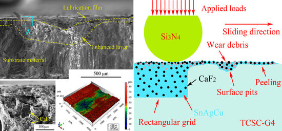
For optimizing the tribological behaviors of sliding bearing, an equal ratio structure of rectangular micro-grid is well constructed and then filled with the SnAgCu-CaF2 (SC) to form a surface micro/nanostructure. The reciprocating wear tests are performed at different sliding frequencies, ensuring that the tribological property at 7 Hz of a TASC-G4 is the best. During wear, the SC in a grid structure migrates to the friction surface and then spreads out to form an SC-rich lubrication film. In this film, a good wrapping in SnAgCu of CaF2 is ensured, helps a plastic enhancement of SnAgCu, an oxidation reduction and the rolling friction of CaF2. These enhance the lubrication film to resist friction damage, reduce sliding resistance, and strengthen interface lubrication, subsequently improves the tribological behaviors of the TASC-G4. The methods and conclusions are obtained to provide an important reference for improving tribological adhibition of the sliding bearings.

Graphical Abstract

1. Introduction

In recent years, the titanium alloy (TA) has been widely applied to reduce the overall weight of aerospace vehicle and achieve a good increase in the flight time and test mileage [1,2], on account of their excellent performances such as low density, high specific strength and the high oxidation resistance [3,4]. When the TA attempts to prepare an aviation bearing, poor friction and wear behaviors are ensured to become main factor for hindering the application ranges of TA [5,6] in a dry sliding process. Hence, an effective improvement of friction and wear behavior of the TA is particularly important for enhancing tribological design and adhibition development of aviation bearing.
Different approaches have been utilized to provide the good lubrication [7,8,9,10]. Shi et al. [7] and Xu et al. [8] successfully prepare the self-lubricating composites containing 10 wt.% Ag using a spark plasma sintering (SPS). They found that during wear, a silver-enriched film for the good lubrication forms on the wear scar. However, a poor binding ability of silver and its substrate results in an ideal distribution of this film, which is unbeneficial in a further improvement of the friction and wear behavior. Subsequently, Liu et al. [9] attempts to prepare the composite lubricant SnAgCu for a good regulation of the binding ability. The result ensures that the binding ability of lubrication film and its substrate is signally enhanced and accomplishes an excellent distribution of the film, thus resulting in a more excellent tribological behavior. However, the SnAgCu-enriched film shows a weak load-bearing ability [10], and easily leads to the film peeling, cross-sectional fracture and subsurface micro-crack at heavy loads, and then hinders a more ideal improvement of lubrication performance.
In this study, in order to improve a bearing ability of the SnAgCu-enriched film for a good lubrication, the CaF2 (CF) with an excellent mechanical property is combined with the SnAgCu [11,12] to construct the composite lubricant SnAgCu-CaF2 (SC). With an important reference of the micro/nanostructures of a butterfly wing [13,14], the micro/nano-grid structures, which mainly comprise the rectangular micro-grid structures and the lubricant SC, are well prepared in the contact surfaces of sliding bearing. Subsequently, the tribological behaviors of an aviation sliding bearing are tested; the self-regulating lubrication function of surface micro/nanostructure is also discussed, along with a coordination mechanism of the SC at different sliding frequencies. Firstly, the rectangular micro/nano-grid structures are designed in the bearing surface that are, thereafter, fabricated into the friction surface of a TA-base bearing using laser-marked technology. Secondly, the SC lubricants are well mixed and are then filled in their respective rectangular micro-structures to prepare surface micro/nano-grid structures by a high-temperature infiltration. Subsequently, dry sliding friction and wear behaviors of TA-base bearings and micro/nano-grid structured self-regulation functions are examined in detail. The tribological behaviors of the matched interfaces are analyzed by observing the collaborative mechanisms of micro/nano-grid structures and the SC. A self-regulating function for a good lubrication is explored to analyze tribological behaviors, on a linear reciprocation friction and wear tester. Herein, the interfacial morphology is analyzed using the field emission scanning electron microscopy (FESEM) and an electro-probe microanalyzer (EPMA). Further, the main element distributions and cross-sectional structures are well determined to reveal the self-regulating function. The empirical methods and obtained results herein are useful for enhancing the tribological design and lubrication adhibition of the aviation bearings.

2. Experimental Procedures

2.1. Material Synthesis

2.1.1. Rectangular Micro-Grid Design of a Bionic Butterfly Wing

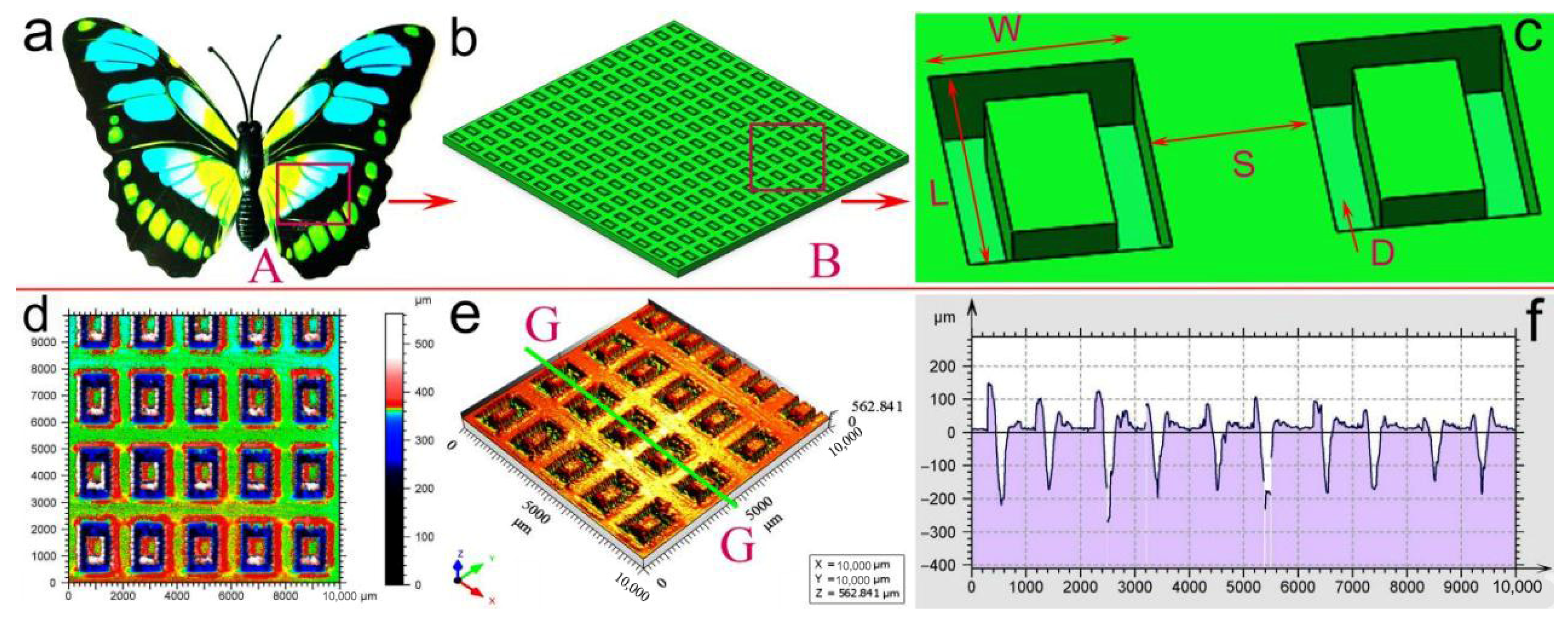
The TA has been widely used to aviation bearings by sliding against the silicon nitrate (Si3N4). However, poor friction and wear properties constantly result in the reduced flight time and test mileage [15]. Recent studies have found that if compared with other micro/nano-grid structures, more advantages such as the regular hierarchical arrangement, precise period distribution, and structure-material cooperation functions are assigned to the butterfly wing. They might be the preferred structures for friction-reducing and wear-resistant property. Hence, inspired by a micro/nanostructure of a butterfly wing, the rectangular micro/nano-grid structures are prepared in a wear surface through a laser-marked technology and are filled using the SC lubricants, in order to improve sliding friction and wear behaviors. Figure 1a shows a butterfly wing, and the typical designs for the rectangular micro-grid structures are indicated in Figure 1b,c. Main preparation procedures of the micro/nano-grid structures in the TA base-surface are elucidated as follows:
With an important reference on the macroscopic and microscopic dimensions of rectangular grid structure for a butterfly wing, we confirm main surface dimensions to design a rectangle TA grid (TA-G) micro-structure, as shown in Table 1, subsequently that are prepared in the TA-base bearing. As can be seen from Table 1, a common ratio of length to width (L:W) of the rectangular micro-grid is selected for 1.33, the structural depth is 100 μm, and the grid spacing is 200 μm. Widths and lengths of the rectangular micro-grids are respectively chosen as 247 and 330 μm for TA-G1, approximately 272 and 363 μm for the TA-G2, 300 and 400 μm endowing for TA-G3. Simultaneously, the TA-G4 is designed as 330 μm in width and 440 μm in length; 363 μm of width and 484 μm of length are carried out for the TA-G5. The designed parameters provide geometric models, as shown in Figure 1b,c, for the subsequent laser processing.

2.1.2. Structure Preparation of the Rectangular Micro-Grids

For the laser-marked micro-grids of the TA-G samples, a laser-marking tester of model No CT-MF30 is used; the relevant LAM parameters are set as follows: laser power of 25–27 kW, the wavelength of 1064 nm, the scanning speed of 400 mm/s, the lasering frequency of 30 KHz, end delay of 200 μs, a corner delay of 100 μs, and a switching delay of 300 μs. After the laser processing, Figure 1d–f show the typical morphologies of scanning planform, 3D profile, and the 2D profile in the specified line GG of Figure 1e of the rectangular microgrid structures. As shown in these figures, the laser-marked mean depth is measured as approximately 200 μm. The results are approximately coincident with the designed dimensions and confirm that main laser-marked parameters herein can guarantee the successful preparation into friction surface of the designed micro-dimensions.

2.1.3. Nano-Lubricant Synthesis of Surface Micro/Nano-Grids

In order to prepare surface micro/nano-grid structures well, the SnAgCu is combined with nano-CaF2 to construct the nano-composite lubricant SC that is thereafter filled into the TA-G micro-structures to construct the rectangular micro/nano-grids (TASC-G) of surface structures. Herein, the SnAgCu is mainly composed of Sn and Ag powders (particle sizes ranging from 5 to 45 μm, purity of more than 99.90%), and Cu powder (10–50 μm size and at least 99.95% purity). The corresponding mass fractions (wt.%) of 90.00, 5.00, and 5.00 for the Sn, Ag, and Cu, respectively. The particle sizes of the CaF2 powders are 500–5000 nm, mean layer thickness is measured as approximately 0.8–1.2 nm, and the corresponding purity is approximately 98.55%. Nano-composite lubricant SC is mainly composed of 75 wt.% SnAgCu and 25 wt.% CaF2. Subsequently, the as-prepared SC nano-lubricant is vibratively mixed using the mixer of model No. MSK-SFM-3. Power of the mixer is 0.25 Kw; 50 Hz in vibration frequency, 220 V in voltage, 1.99 A in current are used in this study; a rotational speed of mixed tester is approximately 1400 r/min. After 30 min of the vibration mixing, the well-distributed mixture of the nano-lubricant SC is obtained, which can provide a good lubrication additive for the hot-pressed infiltration of the SC into the rectangular micro/nano-grid structures.

2.1.4. Hot-Pressed Infiltration of Surface Micro/Nano-Grids

In order to prepare surface micro/nano-grid structure for a good lubrication, vibration-mixed nano-lubricant SC is loaded in a graphite mold with an inner diameter of 30 mm and then placed in an artificial intelligence high-heat furnace (model No. SGM010-13A; manufacturer. Luoyang Xigema Furnace Industry Co., Ltd., Luoyang, China) for an ideal high-temperature infiltration. Further, the SC is well filled into the rectangular micro-grid to construct a micro/nano-grid structure in the TASC-G surface of the sliding bearing, thereby improving its tribological performance. Herein, the applied parameters mainly included infiltration heating at a rate of 5.00 °C/min, after 20 min of the heating, temperatures less than 100.00 °C, pressures in the range of 0.15–0.20 MPa, and an infiltration time of 120 min. After 40 min cooling, the temperature of a furnace cavity is gradually dropped down to 25 °C and obtain the experimental samples of a TASC-G bearing. Hence, when the nano-lubricants, SC, are respectively filled into the TA-G1, TA-G2, TA-G3, TA-G4, and TA-G5, and then the corresponding samples are named as the TASC-G1, TASC-G2, TASC-G3, TASC-G4, and TASC-G5. Before a sliding friction and wear test, the hot-pressed samples are ground to mechanically polish to remove the surface graphite layers, when the emery papers of less than 1200 grit and the wet polishing diamond pastes of lower than 0.05 µm are used in this study. Subsequently, the TASC-G samples with a diameter of 25 mm and a thickness of 6 mm are successfully prepared for the friction tests.
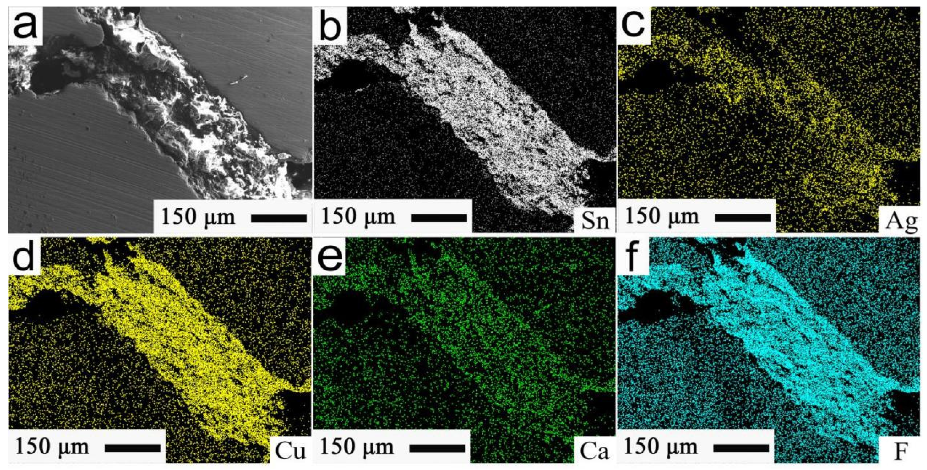
Figure 2 shows the filled morphology of the rectangular micro/nano-grid structures and the distribution of main elements of a TASC-G3 surface. As shown in Figure 2a, an EPMA morphology ensures that a rectangular micro-grid structure is well filled with a large amount of SC. Important distributions of main elements in Figure 2a are indicated in Figure 2b–f. It can be well observed from Figure 2b–f that the main elements of solid lubricants SC, such as Sn (Figure 2b), Ag (Figure 2c), Cu (Figure 2d), Ca (Figure 2e), and F (Figure 2f), are concentrated in a rectangular micro-grid structure. This indicates that the nano-lubricant SC is successfully filled into the micro-grid structure, and a micro/nano-grid structure forms on the friction surface for a good lubrication.

2.2. Tribological Tests of Surface Micro/Nano-Grid Structure

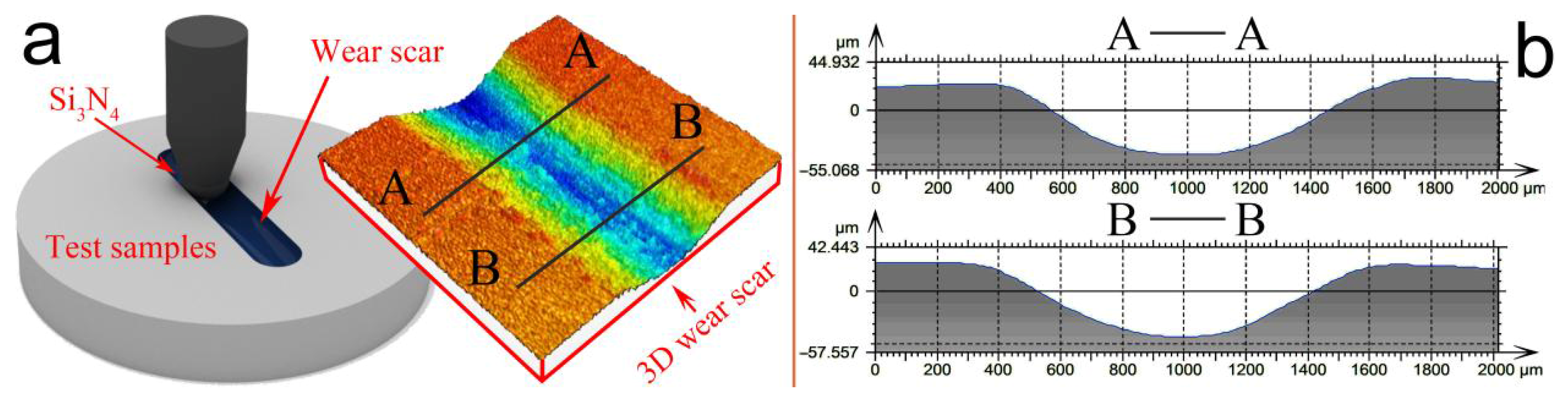
For exploring the effect of the proportional grid micro/nanostructure on sliding tribological properties of an aviation bearing, dry sliding friction and wear experiments are carried out, on a reciprocating friction and wear tester of model No. MMX-1. Figure 3a shows the friction schematic of the TASC-G by sliding against the Si3N4 balls. As shown in Figure 3a, according to an ASTM standard of G99-95 [16], friction and wear properties of the sliding bearings are well measured at room temperature, when the Si3N4 ball is reciprocally driven in a straight sliding line. Herein, the Si3N4 ball with a diameter of 6 mm is used, along with mean Vickers hardness of approximately 15.54 GPa. The dry wear test is carried out on the bearing sample, under a load of 10 N and the sliding frequencies of 5–13 Hz. The friction coefficients for 30 min are recorded in real time using the computer control system, aiming to analyze an anti-friction behavior of the bearing. The 3D contour structure of a wear scar is tested by a surface profilometer of model No. ST400, and the result is shown in Figure 3a. After more than five tests, the 2D line profiles are extracted from the straight lines AA and BB of Figure 3a and are then shown in Figure 3b. A subsequent calculation is well carried out for the cross-section area A of wear scar and facilitates an acquirement of the wear-scar volume O, as shown in Formula (1). Subsequently, a sliding wear rate T of the TASC-G can be calculated as Formula (2) [17,18], which mainly aims for a good assessment of wear-resistance behaviors of sliding bearings:
O = L × A
T = O⁄(F × S)
herein, S represents the total dry sliding distance (m); F is the friction load (N); O is a wear volume of a wear scar (mm3); L is the length of a wear scar (mm); A represents the cross-sectional area of a wear scar (mm2).

3. Results and Discussion

3.1. Analysis of Friction and Wear Performances

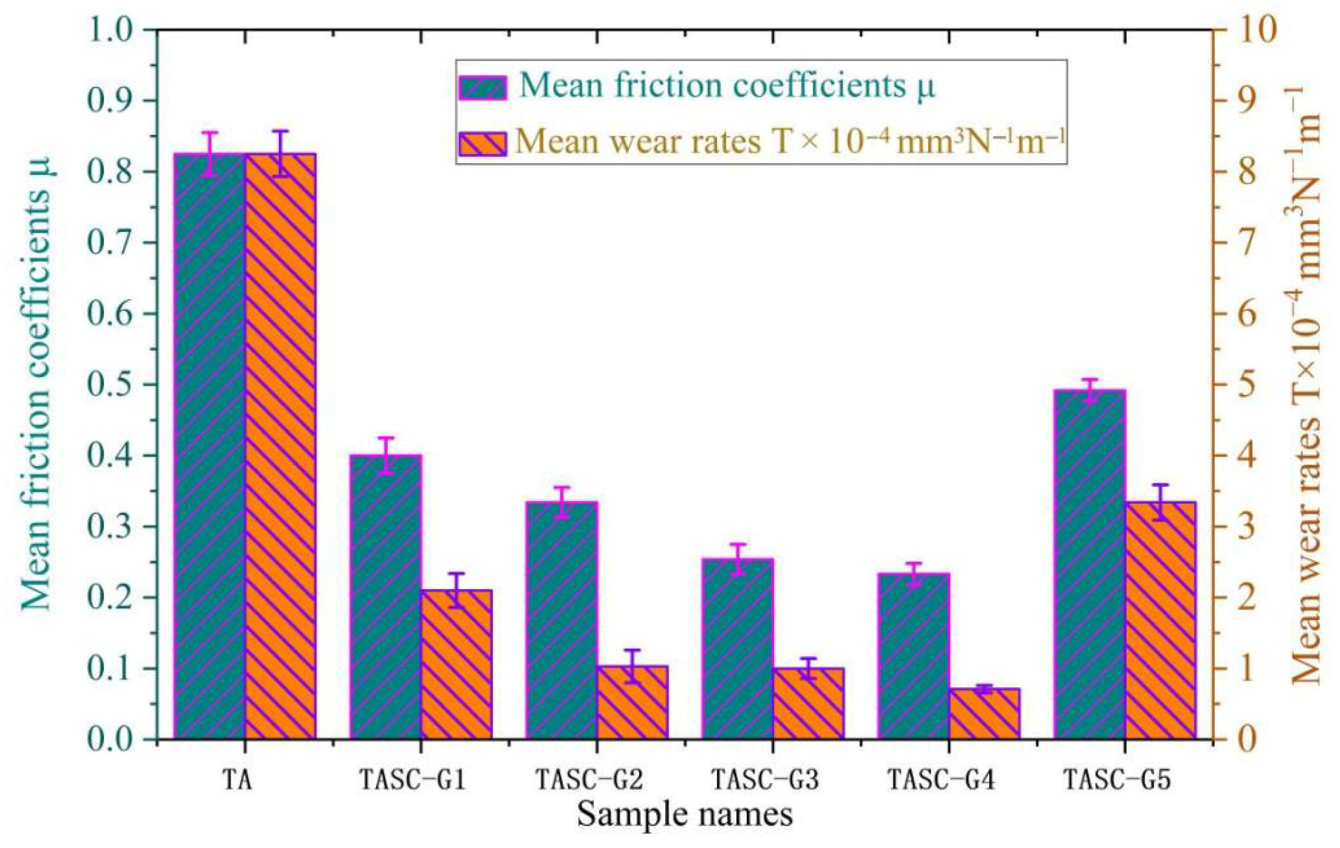
Figure 4 shows the friction coefficients and wear rates of the TA and TASC-G samples. As shown in Figure 4, the micro/nano-grid structures are prepared to well accomplish the reduction in the friction coefficients and wear rates, and result in that tribological properties of the TASC-G are more excellent, if compared with that of a TA sample. Simultaneously, it is found that with the continuous increase in the length-width dimensions of grid structures, sliding friction coefficients of the as-prepared samples from TASC-G1 to TASC-G4 gradually reduce, subsequently increase from TASC-G4 to TASC-G5. Hence, this results in the best friction and wear behaviors of the TASC-G4 with the micro/nano-grid structure of length:width = 440:330, along with approximately 0.233 for friction coefficient and 0.71 × 10⁻⁴ mm3N−1m−1 in wear rate.
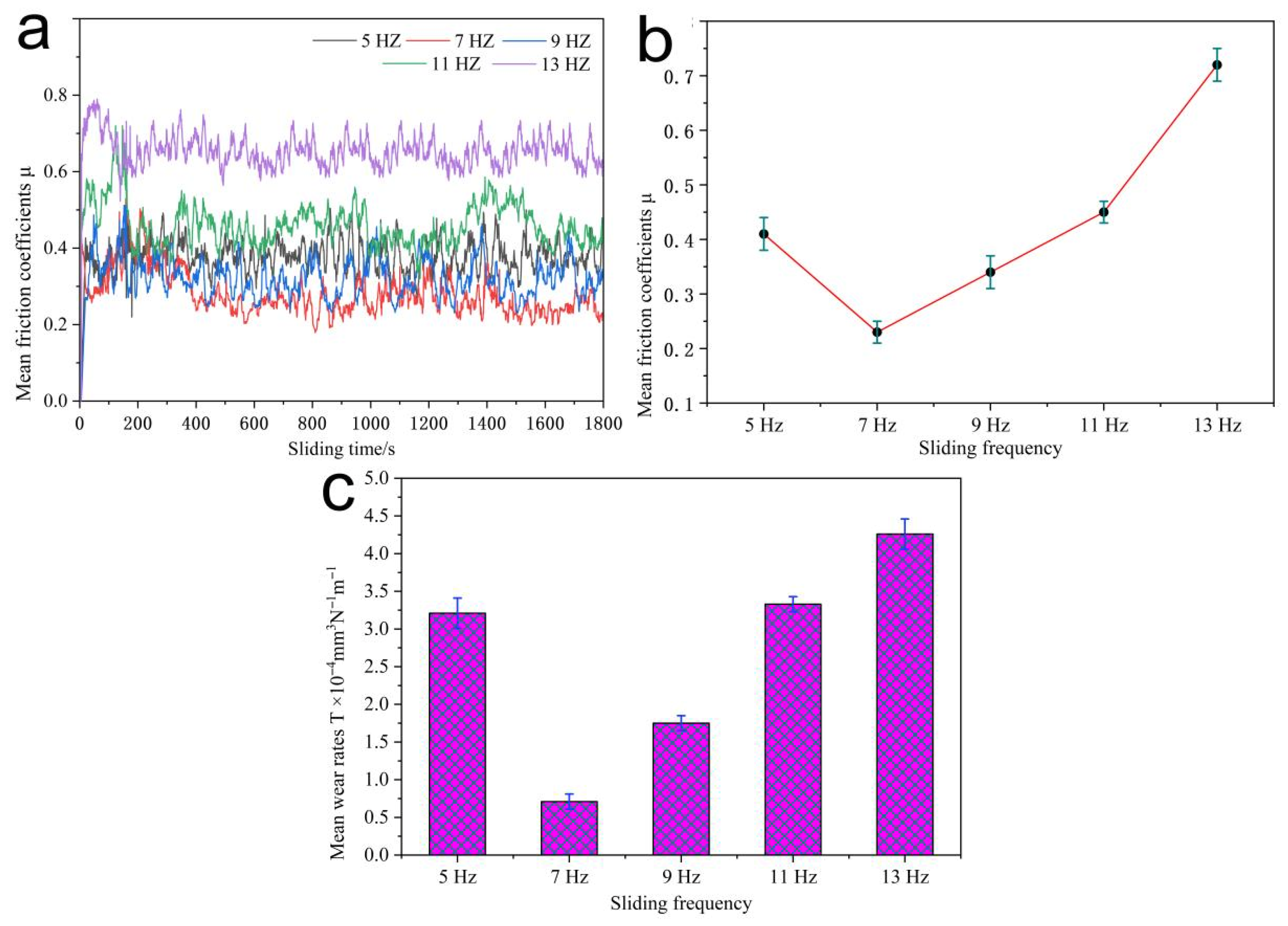
Engineering applications indicate that increase in the reciprocating sliding frequency is an important influence factor for the service accuracy and working life of an aviation bearing. Hence, in order to study effect of sliding frequency on the frictional performances, experimental tests are conducted for friction coefficients and wear rates of TASC-G4, and the results are reported in Figure 5. The instantaneous friction coefficients of the TASC-G4 at different sliding frequencies are shown in Figure 5a. As shown in Figure 5a, it can be known that the friction process can be divided into the running-in wear stage and a stable wear stage, according to the variation curves of friction coefficients. It is because that slight unevenness and fine hard-particles of the TASC-G4 surface result in the rapid increase in friction coefficients, at the sliding time of 0–70 min; this stage can be named as a running-in wear stage. When a continuous wear test is carried out after 7.00 min, the lubricant SC and a small number of wear debris are migrated to a wear surface, and repair the damaged wear scar to stabilize the friction coefficients, and then a stable wear stage is lasted from 7.00 min to 30.00 min.
Figure 5b,c show the mean friction coefficients and wear rates of the TASC-G4 samples at different sliding frequencies. As can be seen from Figure 5b,c, with an increase from 5 Hz to 7 Hz of sliding frequencies, the friction coefficient and wear rate of the TASC-G4 gradually reduce and then show a rising trend at the sliding frequencies ranging from 7 Hz to 13 Hz. Hence, it can be concluded that if compared with those at 5 Hz, 9 Hz, 11 Hz and 13 Hz, the friction coefficient (approximately 0.233) and wear rate (almost 3.21 × 10⁻⁴ mm3N−1m−1) of the TASC-G4 are smaller at 7 Hz.

3.2. Tribological Mechanism Analysis

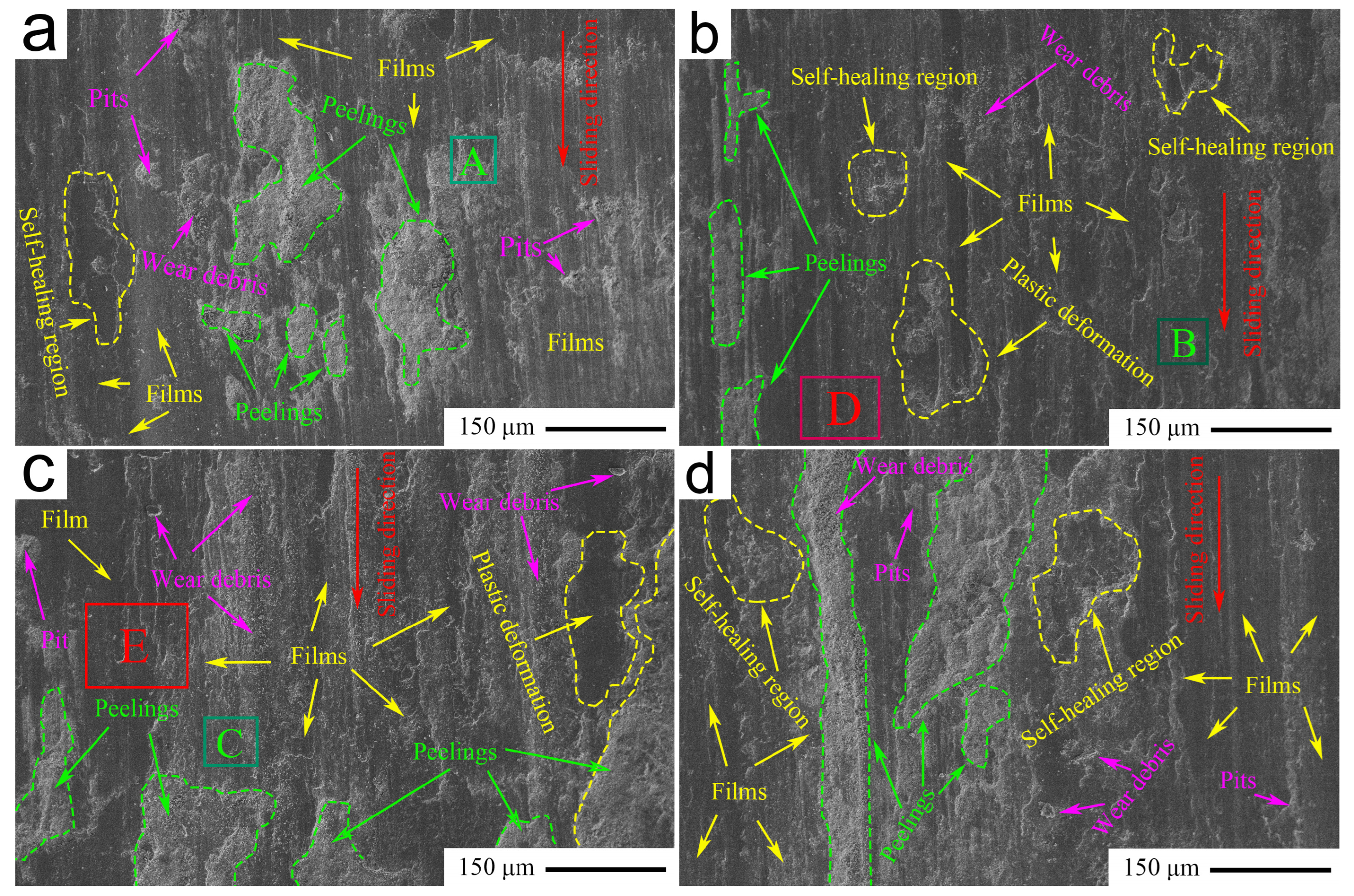
In order to explore the effect of sliding frequency on tribological mechanism of a TASC-G4, the FESEM instrument is applied to characterize the microscopic morphologies of the wear scars of TASC-G4 at different sliding frequencies; the results are shown in Figure 6. It can be clearly seen from Figure 6a that at 5 Hz, the pits and slight wear debris are found on the wear surface of the TASC-G4; simultaneously, the lake-liked areas of surface peeling and self-healing appear in a wear scar. Hence, main wear mechanisms of the TASC-G4 are abrasive wear and fatigue peeling. Table 2 shows the mass fractions of main elements in the green rectangular areas A, B and C in Figure 6. As can be seen from Table 2, the mass fractions of Ti and Sn elements in the green rectangle area A of Figure 6a are 24 wt.% and 18 wt.%, respectively; it ensures that main elements in the peeling area are the substrate Ti and lubricant SnAgCu. It is a possible fact that structural edge of a rectangular grid occurs an insufficient deformation under the repeated sliding of friction stress, and results in that a small amount of SC is squeezed out of the grid structure, enriched to a friction surface; thus, an unideal repairing produces result in a poor self-healing of wear scar. The poor tribological behaviors are obtained for the TASC-G4 at 5 Hz, along with a sliding friction coefficient of approximately 0.42 and mean wear rate of approximately 3.21 × 10⁻⁴ mm3N−1m−1.
Compared with a wear-scar morphology at 5 Hz, the fine wear-debris particles are scattered on a wear scar at 7 Hz; the small areas of self-healing and peeling are well observed on the wear scar of the TASC-G4. As shown in Table 2, the mass fractions of main elements in a green rectangle B of Figure 6b are 21 wt.% Sn, 5 wt.% Ag, 7 wt.% Cu, 13 wt.% Ca, 8 wt.% F, respectively. It indicates that a rectangular B area is mainly composed of the SC. A sliding frequency of 7 Hz improves the wear scar temperatures, facilitates an expansion of SC, subsequently provides an excellent enrichment of the SC, promoting a good formation of the lubrication film. Furthermore, this film serves as the new type of contact interface to exist the friction matching pairs of the TASC-G4 sliding against the Si3N4 ball, thus acquiring a good lubrication; it results in the smaller friction coefficient of approximately 0.23 and wear rate of approximately 0.71 × 10⁻⁴ mm3N−1m−1 at 7 Hz, if compared with those at 5 Hz.
As shown in Figure 6c, it is observed that the larger areas of surface peeling are accompanied by a large amount of wear debris; meanwhile, a plastic deformation area and the small regional film for the lubrication appear on a wear scar of the TASC-G4. It indicates a wear mechanism of surface peeling at sliding frequency of 9 Hz. As shown in Table 2, the mass fractions of main elements in a green rectangle C of Figure 6c are 20 wt.% Sn and 11 wt.% Ca and then ensure a presence of the SC on a wear scar. It is indicated that the SC lubricants appear on a wear scar to occur a plastic deformation for repairing of a friction surface; however, the self-healing ability of the lubricant SC is lower than the damage of a friction surface caused by sliding friction force. Thus, it results in an observed peeling of wear scar and forms a lubrication film in a small region. Subsequently, an insufficient lubrication is ensured to facilitate a TASC-G4 to acquire a poor tribological behavior at 9 Hz, approximately 0.34 in friction coefficient and 1.75 × 10⁻⁴ mm3N−1m−1 for wear rate.
When sliding frequency is chosen as 11 Hz, the typical FESEM morphology of a TASC-G4 is shown in Figure 6d. As shown in Figure 6d, larger areas of surface peeling and the small pits appear on a wear scar to injure the lubrication film, if compared to those at 5 Hz (Figure 6a), 7 Hz (Figure 6b) and 9 Hz (Figure 6c); smaller self-healing regions occur on the wear scar at 11 Hz. Hence, main wear mechanism of a TASC-G4 at 11 Hz is severe peeling. It indicates that the self-healing occurs on a wear scar to provide an insufficient ability and results in the severe peeling of wear scars, thus facilitates a poor friction and wear behavior at 11 Hz of the TASC-G4; mean wear rate and friction coefficient are approximatively 0.45 and 3.33 × 10⁻⁴ mm3N−1m−1, respectively.
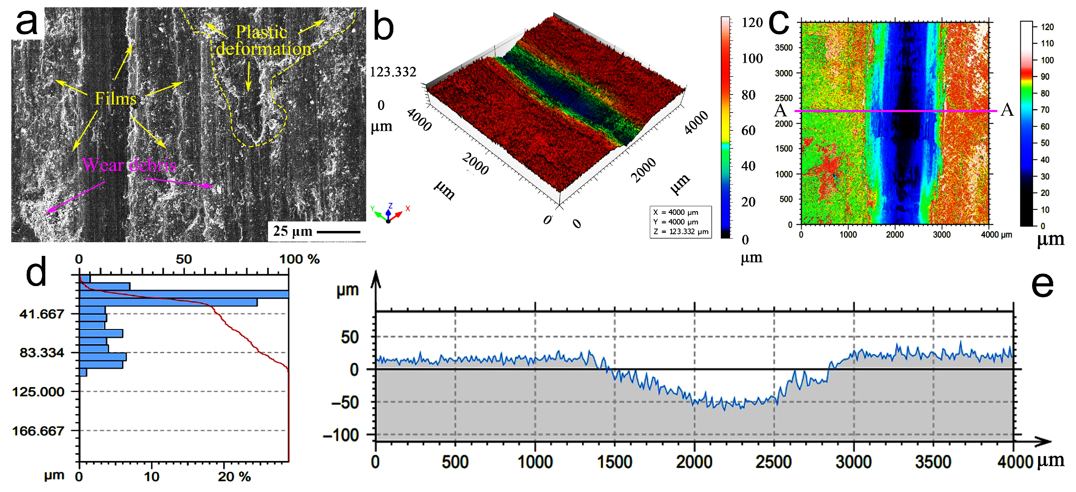
When the sliding wear tests are carried out at 7 Hz, the FESEM morphology and main parameters of the wear scars of the TASC-G4 are indicated in Figure 7. The further amplification morphology of a red rectangle D in Figure 6b obtained by a FESEM of wear scar is indicated in Figure 7a. As shown in Figure 7a, a lubrication film presents a continuous distribution state along a sliding wear direction; the plastic deformation region and a small number of fine wear debris are well observed on the lubrication film. During wear, a lubrication film cooperated with a large amount of wear debris show an enhanced function for a good self-healing of the wear scar, significantly improve the lubrication behavior of the friction interface. Figure 7b shows the 3D profile morphology of a scanned area. Figure 7c is a simulated cloud morphology of height distribution of the scanned area (4000 μm × 4000 μm) of wear scars of the TASC-G4. After the parameter detection, the main height parameters of Figure 7b, Sq: 22.94 µm, Ssk: −1.064, Sku: 3.031, Sp: 47.697 µm, Sv: 75.635 µm, Sz: 123.332 µm, Sa: 18.585 µm, Smc: 21.472 µm, and Smr: 6.219 × 10⁻⁴%, are measured on a 3D surface morphology instrument of model No. ST 400.
Subsequently, the parameter statistic of surface height for the scanned area is indicated in Figure 7d. A statistical result ensures that the proportion of micro-surface heights within the range of 0.000 μm to 41.667 μm is approximately 67%; a proportion of height range from 66.667 μm to 108.334 μm is approximately 21%. Figure 7e expresses the 2D height distribution profile along the straight-line AA in Figure 7c and indicates a smooth wear scar to be formed at 7 Hz. Hence, it is concluded from the aforementioned discussions that a relatively flat and smooth morphology of the wear scar is obtained at 7 Hz. It indicates that the wear scar has good integrity; an unobvious fracture or peeling phenomenon is observed. In addition, the 3D morphology and characteristic curves of the wear scars show the unobvious concave and convex structures of the friction surface; this ensures that the SC lubricants show an excellent self-healing function for maintaining the smooth and flat surface of a wear scar, thus the TASC-G4 samples achieve a significant reduction in friction coefficients and wear rates, at the sliding frequency of 7 Hz.
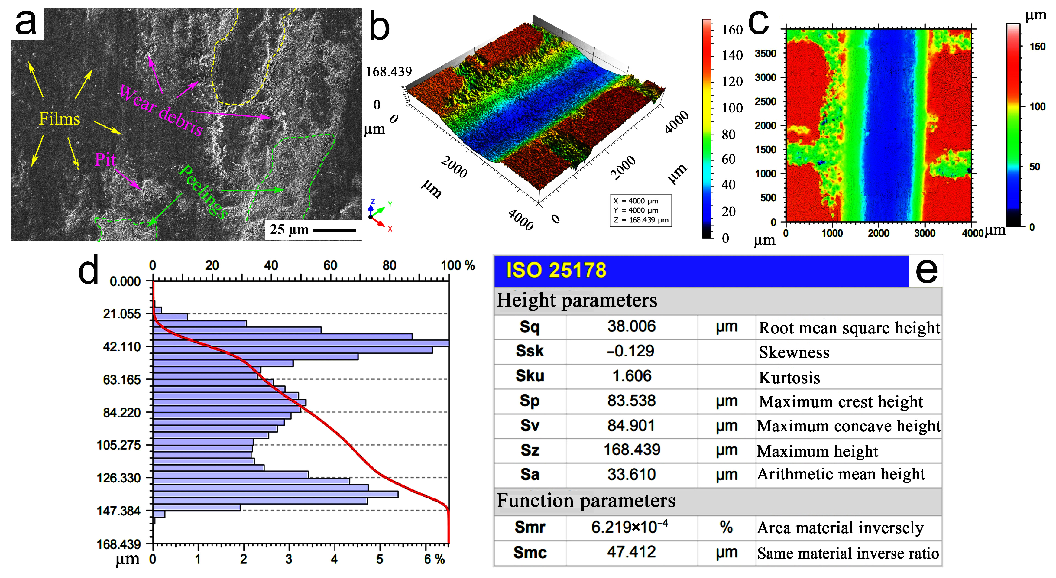
A typical FESEM amplification morphology, 3D structure and corresponding characteristic parameters of the wear scars of a TASC-G4 at 9 Hz are shown in Figure 8. As shown in Figure 8a, the further amplification morphology of a red rectangle E in Figure 6c obtained by the FESEM of wear scar indicates that the big peeling, wear debris, surface pits and an incomplete lubrication film are found on the wear surface. It shows a main wear mechanism of surface peeling. This is probably because an increase in sliding frequency generates a large amount of frictional heat and the high impact damage on a wear scar and then results in a non-ideal damage of friction surface. It causes a lubrication film to be peeled and produces the wear debris and surface pits on the wear scars.
Figure 8b,c show the 3D profile and 2D cloud morphology of scanning area, respectively. Subsequently, a parameter statistic of surface height of the corresponding wear scar is indicated in Figure 8d, and the corresponding height parameters are shown in Figure 8e. After the examination, the main height parameters of Figure 8c are Sq: 38.006 µm, Ssk: −0.129, Sku: 1.606, Sp: 83.538 µm, Sv: 84.901 µm, Sz: 168.439 µm, Sa: 33.610 µm, Smr: 6.219 × 10⁻⁴%, Smc: 47.412 µm, which are higher than that at 7 Hz, thus indicating a unevenness wear scar with the convex and concave structures. It ensures a non-ideal damage of frictional surface, accelerates the friction resistance increase and surface material loss, and acquires the higher friction coefficients and wear rates at 7 Hz, if compared with those at a sliding frequency of 9 Hz.
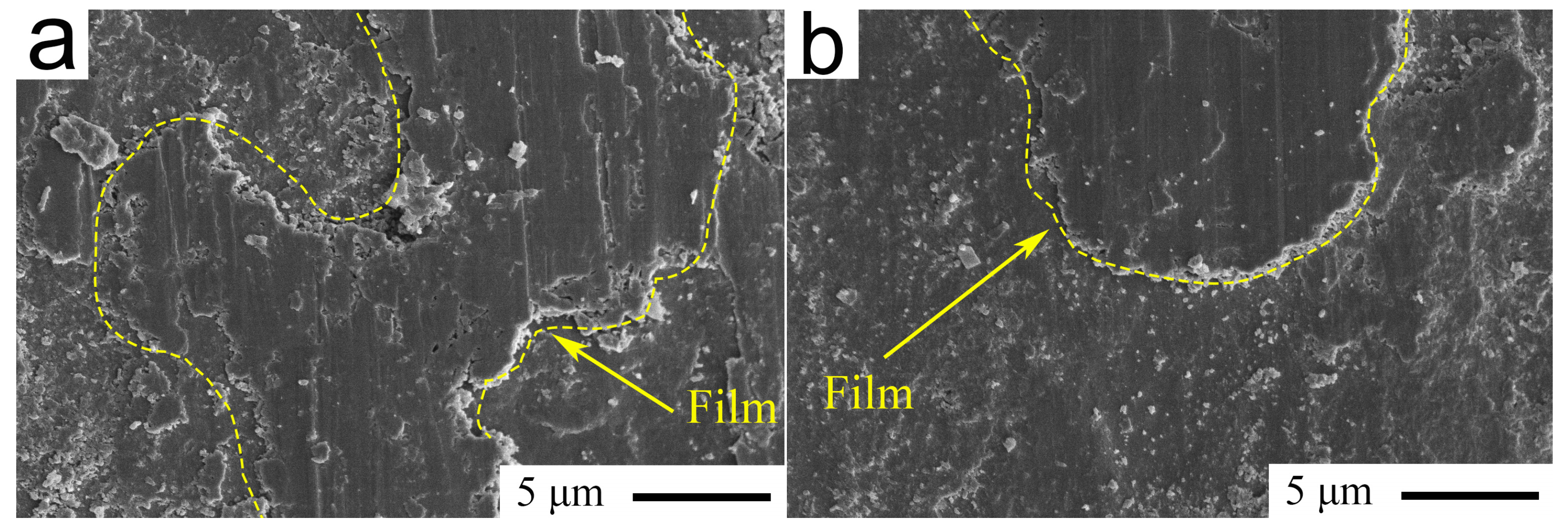
Figure 9 shows the FESEM morphologies of the wear scars of Si3N4 balls at different sliding frequencies. As shown in Figure 9a, the transfer film is found on a wear scar of spherical Si3N4 at 7 Hz. It indicates that at the continuous action of 7 Hz sliding frequency, a good deal of the SC in a rectangular grid structure with a length-to-width ratio of 440:330 of TASC-G4 is extruded, and accumulates the surface spreading on a wear scar, thus forming a large-scale transferring film. It hinders the direct contact between the friction interfaces and effectively reduces the frictional coefficients and wear rates. Figure 9b shows the FESEM morphology at 9 Hz of the wear scar of a Si3N4 ball. It can be clearly seen from this figure that a smaller area of the transfer film appears on the wear scar of Si3N4 ball at 9 Hz, if compared to that at 7 Hz. It is probably because high sliding frequency (9 Hz) results in a large amount of SC to be removed out from a wear scar and promotes a slight migration of SC to a wear scar, thus forming a small area of transfer film on the Si3N4 ball. If compared with those at 7 Hz, although a transfer film helps to reduce the direct contact between Si3N4 ball and TASC-G4 sample; but, due to the distribution area of lubrication film being relatively small, it limits the lubrication ability, subsequently resulting in that the friction coefficient and wear rate at 9 Hz of TASC-G4 are relatively larger, if compared to those at 7 Hz.
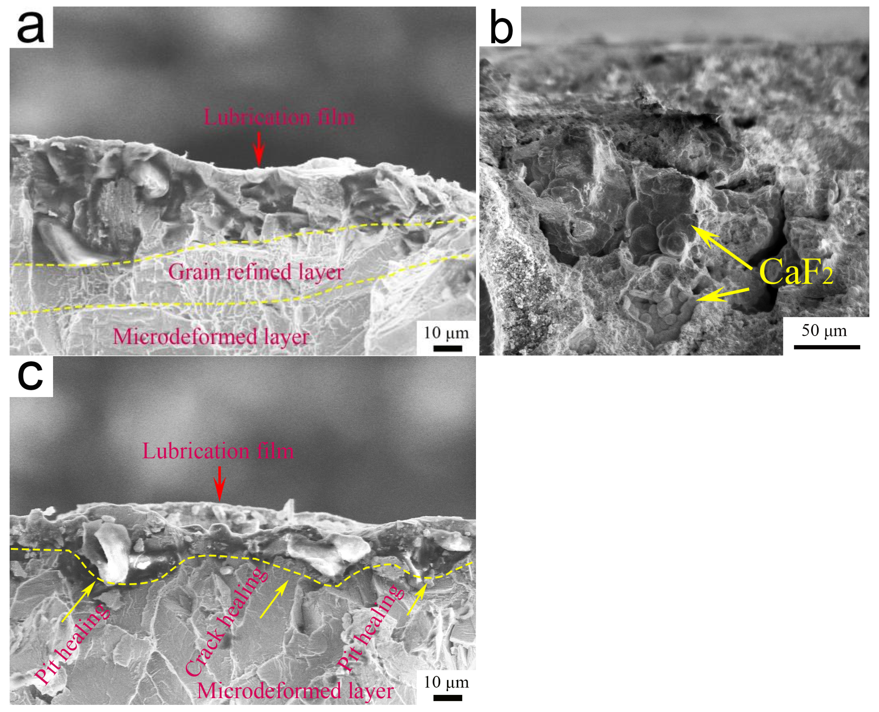
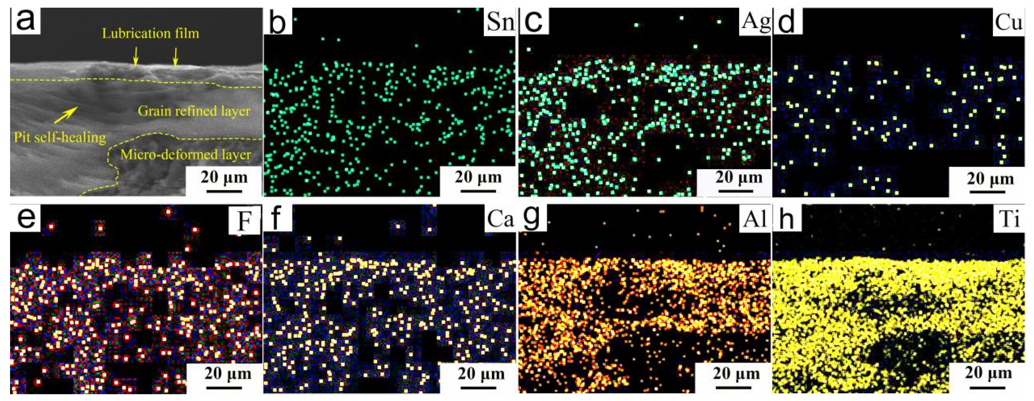
In order to further analyze the tribological behaviors, the typical FESEM profiles of the wear-scar cross-sections of the TASC-G4 at 7 Hz and 9 Hz are indicated in Figure 10. As shown in Figure 10a, a distinct stratified structure at 7 Hz is mainly composed of a lubrication film, the grain refinement layer and a micro-deformation layer. As can be seen from Figure 10b, the spherical CaF2 particles appear in the cross-section of the micro/nano-grid structure. This might be due to a fact that at 7 Hz, the SC lubricants are continuously squeezed out from the grid structure and spread on the wear scar to form a lubrication film. This formed film is beneficial for improving tribological behavior and facilitates the small friction coefficient and wear rate to be obtained at 7 Hz.
As shown in Figure 10c, a lubrication film appears on the micro-deformed layer at 9 Hz; simultaneously, the self-healing morphologies for the pits and cracks in the cross-sections of the TASC-G4. The interface pits and cracks are probably because higher sliding frequency (9 Hz) produces a greater impact force and causes the greater damages of wear scars, thus resulting in an unexpected appearance of pits and cracks. A good formation of a lubrication film may be due to the fact that in the friction and wear process, the SC enters the pits and cracks, an effective repairing is carried out for the wear scars; the SC lubricants are enriched on the wear scars, and facilitates a formation of the lubrication film on a micro-deformed layer.
Hence, if compared with that at 9 Hz, a three-layer hierarchical structure is formed at 7 Hz, resulting in that the grain refinement layer and micro-deformation layer appear under the lubrication film, providing a more excellent support for lubrication film. Meanwhile, the three-layer structures can preferably protect the wear scar during sliding wear, reduce the friction damage and material loss, and improve the better anti-friction and anti-wear behavior at 7 Hz of the TASC-G4. Thus, better lubrication appears at 7 Hz, if compared to that at 9 Hz.
In order to examine main element distributions of a three-layer structure at 7 Hz, the typical FESEM morphology and main element distributions of the wear scar cross-sections of TASC-G4 are shown in Figure 11. As can be seen from Figure 11a that a three-layered structure is mainly comprising lubrication film, grain refined layer and the micro-deformation layer. Additionally, an expected self-healing occurs for repairing the microcosmic pits in a grain refined layer. The typical distributions of main elements such as Sn, Ag, Cu, F, Ca, Al and Ti are indicated in Figure 11b–h. This ensures that a large amount of SC is enriched in the stratified structure and provides a good lubrication for reduction in sliding friction resistance and surface material loss. Hence, it can be concluded that during wear, the SC lubricants are squeezed out of the grid structures, and enriched on a wear scar, subsequently spread into a well-proportioned distribution, thus resulting in the good formation on a grain refined layer of the lubrication film. Further, an excellent tribological behavior of the lubrication film is provided for a collaborative function of SnAgCu an CaF2.
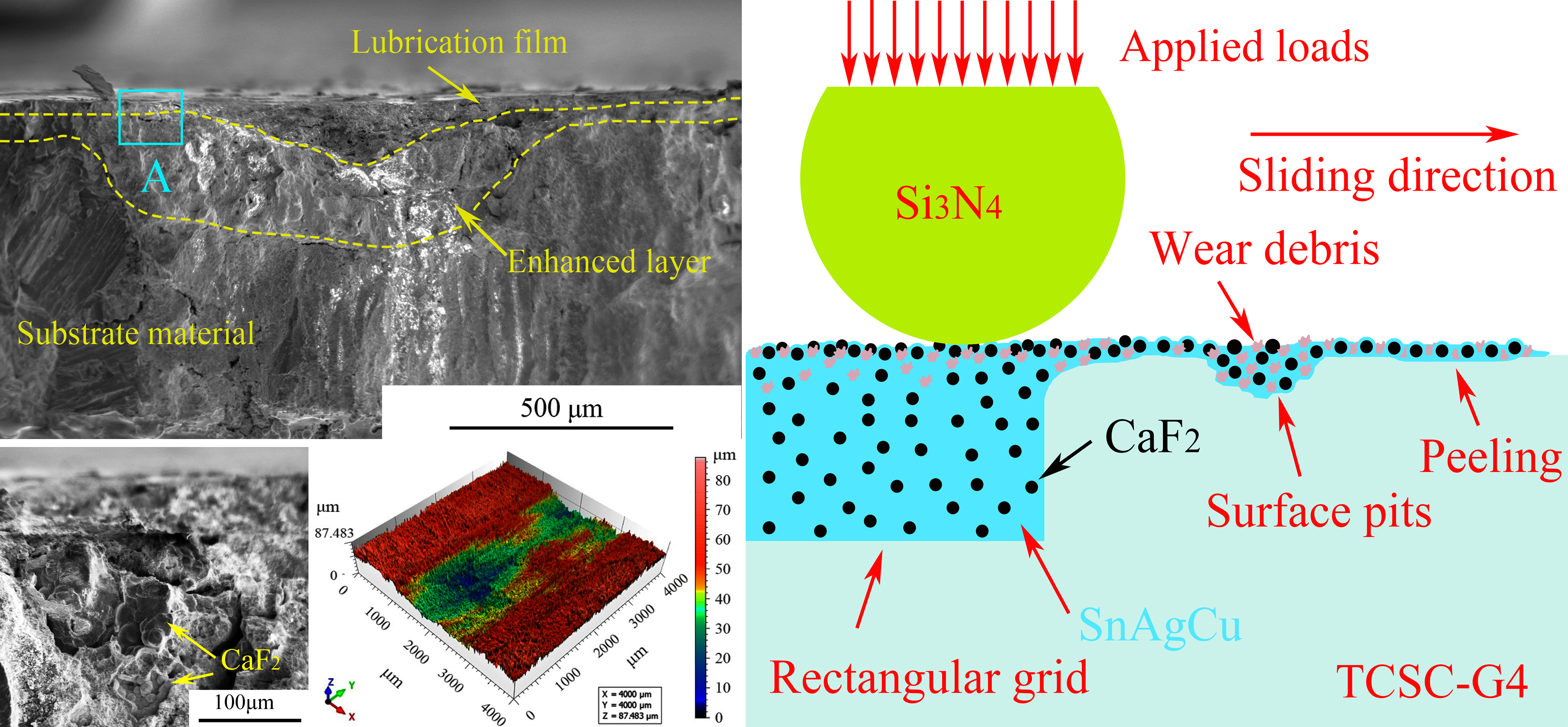
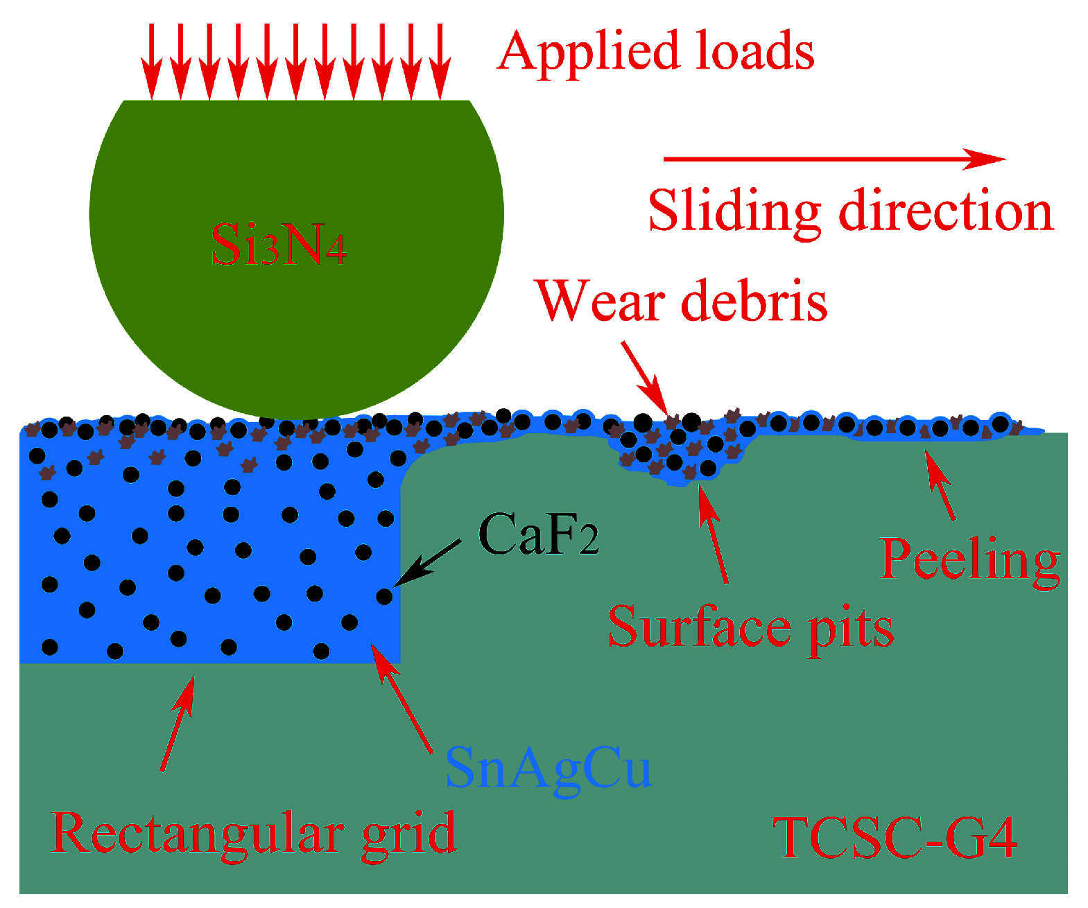
In order to reveal the lubrication mechanism at 7 Hz, in accordance with the aforementioned discussions, a schematic chart showing the lubrication mechanism of TASC-G4 is indicated in Figure 12. As can be seen from Figure 12, under the action of normal loads and friction forces, the SnAgCu and CaF2 lubricants in the rectangular grid structures are extruded to the friction surface. During wear, plastic deformation of the SC occurs, and then continuously spreads to a wear scar for the repeated sliding friction forces, thus forming a lubrication film. The CaF2 increases the plastic deformation of SnAgCu and improves the bearing abilities of the lubrication film. When the Si3N4 balls are repeatedly slid in a straight line, the SC lubricants repair the pits and peelings of wear scars. In addition, the wear debris, spherical CaF2 and soft SnAgCu are enriched in the lubrication film, which play a good reinforcement role in improving friction-reducing and wear-resistant ability, thus maintaining an excellent lubrication function. Meanwhile, as friction continues, a large amount of frictional heat accumulates on a wear scar and increases the plastic deformation of SnAgCu. It causes the CaF2 particles to be encapsulated into SnAgCu to gradually be exposed to a lubrication film and then come into direct contact with the Si3N4 balls. At this point, main wear mechanisms of the TASC-G4 are altered from sliding friction to rolling friction, because of spherical CaF2 rolling, thus reducing the direct contact of a friction pair, which is helpful in lowering friction resistance and material loss of the TASC-G4. Subsequently, it enables the lubrication film to show a good lubrication and effectively improves the tribological property of TASC-G4, along with friction coefficient of approximately 0.23 and wear rate of approximately 0.71 × 10⁻⁴ mm3N−1m−1. Therefore, at the sliding frequency of 7 Hz, the TASC-G4 achieves excellent lubrication, and results in significant improvement of sliding tribological properties.

4. Conclusions

In this study, the effect of sliding frequency on tribological property of the bearing sample with an equiproportional rectangular grid-structure is explored in detail; the main conclusions are summarized as follows:
(1)
The micro/nanostructure of butterfly wings are referred to design the rectangular grids on a wear surface, which is prepared by a laser-marked method; subsequently, the nano-lubricants of the SC are filled into the micro-grids by the hot-pressed infiltration, thus constructing the rectangular micro/nano-grid structures of the TASC-G.
(2)
The friction and wear test is conducted; the results ensure that the best tribological behavior is obtained for the TASC-G4 at 7 Hz; this is probably because that an aspect ratio of 440:330 for the micro/nano-grid structure of TASC-G4 is beneficial for acquiring a best tribological behavior.
(3)
When the sliding frequencies increase from 5 Hz to 7 Hz, the temperature rise in friction surface and the deformation increase in micro-grid structures, promotes the migration and accumulation of more SC on a wear surface, thus enhancing a lubrication ability of TASC-G4. When sliding frequencies increase from 7 Hz to 11 Hz, the increased sliding speeds result in the damaged surfaces, deteriorates the contact interface, and acquire the reduced lubrication behaviors, thus the TASC-G4 acquire the smallest friction coefficient (0.23) and wear rate (0.71 × 10⁻⁴ mm3N−1m−1) at 7 Hz.
(4)
The SnAgCu produces a plastic flow during wear and effectively fills into the surface pits and cracks for a self-healing wear scar at 7 Hz. The SC lubricants are abundantly enriched on a wear scar, facilitate a lubrication film to form, thus provide a good lubrication.
(5)
Under the combined actions of forces and temperatures, the SnAgCu in a lubrication film encloses spherical CaF2 and occurs a ball rolling, that is conducive to reducing friction resistance and material loss, thus improving the tribological properties of TASC-G4.
(6)
Spherical CaF2 is wrapped in the SnAgCu to cause a plastic deformation of the lubrication film; soft SnAgCu is coated on spherical CaF2 to reduce the binding force of the CaF2 and substrate material, thus providing an ideal effect of rolling wear. Hence, collaborative functions of SnAgCu and CaF2 guarantee small friction resistance and material loss of the lubrication film, and result in an excellent tribological behavior of a TASC-G4.

Author Contributions

Conceptualization, Y.M. and K.Y.; methodology, Y.M., K.Y. and J.T.; formal analysis, Y.M., K.Y., J.T. and Y.T.; investigation, Y.M. and K.Y.; resources, K.Y. and J.T.; data curation, Y.M. and Y.T.; writing—original draft preparation, Y.M. and J.T.; writing—review and editing, K.Y. and Y.T.; visualization, K.Y. and Y.T.; supervision, K.Y. and Y.T.; project administration, Y.M. and J.T.; funding acquisition, K.Y. All authors have read and agreed to the published version of the manuscript.

Funding

The work was financially supported by the Anyang Institute of Technology Key Laboratory of Functional Materials and Remanufacturing Technology of Aviation Equipments (SYS202406); Henan postdoctoral Science Foundation (HN2025153) and the Project for Science and Technology Plan of Henan Province (252102221038).

Data Availability Statement

The original contributions presented in the study are included in the article, further inquiries can be directed to the corresponding authors.

Conflicts of Interest

The authors declare no conflicts of interest.

References

  1. Su, J.L.; Jiang, F.L.; Teng, J.; Chen, L.Q.; Yan, M.; Requena, G.; Zhang, L.C.; Wang, Y.M.; Okulov, I.; Zhu, H.M.; et al. Recent innovations in laser additive manufacturing of titanium alloys. Int. J. Extrem. Manuf. 2024, 6, 032001. [Google Scholar] [CrossRef] [Scilit]
  2. AbouelNour, Y.; Gupta, N. In-situ monitoring of sub-surface and internal defects in additive manufacturing: A review. Mater. Des. 2022, 222, 111063. [Google Scholar] [CrossRef] [Scilit]
  3. Ni, C.B.; Zhu, J.J.; Zhang, B.G.; An, K.; Wang, Y.Q.; Liu, D.J.; Lu, W.; Zhu, L.D.; Liu, C.F. Recent advance in laser powder bed fusion of Ti-6Al-4V alloys: Microstructure, mechanical properties and machinability. Virtual Phys. Prototyp. 2025, 20, e2446952. [Google Scholar] [CrossRef] [Scilit]
  4. Yadav, S.; Mukherjee, M.; Singh, D. Review of current challenges in the implementation of WAAM for Ti-6Al-4 V alloys. Int. J. Adv. Manuf. Technol. 2024, 133, 2103–2130. [Google Scholar] [CrossRef] [Scilit]
  5. Rundora, N.R.; Klenam, D.E.P.; Polat, S.; Mathabathe, N.M.; van der Merwe, J.; Bodunrin, M.O. Dry Sliding Wear Behavior of Experimental Low-Cost Titanium Alloys. Tribol. Trans. 2024, 67, 560–572. [Google Scholar] [CrossRef] [Scilit]
  6. Ashkani, O.; Moazami-Goudarzi, M.; Abbasi, A. Enhanced mechanical properties and wear resistance of titanium by Mn addition. Mater. Today Chem. 2025, 44, 112168. [Google Scholar] [CrossRef] [Scilit]
  7. Shi, X.L.; Xu, Z.S.; Wang, M.; Zhai, W.Z.; Yao, J.; Song, S.Y.; ud Din, A.Q.; Zhang, Q.X. Tribological behavior of TiAl matrix self-lubricating composites containing silver from 25 to 800 °C. Wear 2013, 303, 486–494. [Google Scholar] [CrossRef] [Scilit]
  8. Xu, Z.S.; Zhang, Q.X.; Zhai, W.Z.; Li, X.X. Analytical model and experimental validation of the local damage mechanism of solid lubricant films for metal matrix self-lubricating composites. RSC Adv. 2015, 5, 74850–74857. [Google Scholar] [CrossRef] [Scilit]
  9. Liu, X.Y.; Shi, X.L.; Huang, Y.C.; Deng, X.B.; Yan, Z.; Xue, B. Anti-friction and wear properties of the friction interface of M50-10 wt%(50Sn40Ag10Cu) composite. J. Alloys Compd. 2018, 765, 7–17. [Google Scholar] [CrossRef] [Scilit]
  10. Yang, K.; Ma, H.R.; Cao, S.T.; Li, X.X.; Li, A.H.; Cao, Z.Z. Analysis of friction interfaces with sinusoidal microchannels and the hybrid lubrication mechanisms of a tribo-film. Appl. Surf. Sci. 2020, 525, 146502. [Google Scholar] [CrossRef] [Scilit]
  11. Zhang, Z.H.; Deng, J.X.; Cao, S.H.; Wang, R.; Wu, J.X.; Lu, Y.; Bao, Y.C. Microstructure and high-temperature tribological properties of electro-jet mask printing (CFx)n/CaF2-ZrO2 interlaced coatings. Compos. Part A Appl. Sci. Manuf. 2025, 195, 108978. [Google Scholar] [CrossRef] [Scilit]
  12. Shan, C.; Kou, H.M.; Jiang, D.P.; Liu, R.R.; Zhang, Z.; Lu, Z.W.; Fang, L.Z.; Han, P.; Lian, Y.F.; Peng, X.; et al. Nanosecond laser-induced surface damage growth and its mechanism of single crystal CaF2 (111) at 193 nm. Opt. Express 2025, 33, 15067–15080. [Google Scholar] [CrossRef] [Scilit] [PubMed]
  13. Satija, I.I. Interplay between topology and fractality of the Hofstadter butterfly. Phys. Lett. A 2025, 552, 130635. [Google Scholar] [CrossRef] [Scilit]
  14. Zhong, B.; Guo, W.L.; He, D.Y.; Xing, Z.G.; Huang, Y.F.; Lv, X.R. Anti-reflective properties of butterfly-wing-micro-nano structures in the infrared band. Opt. Laser Technol. 2024, 169, 109863. [Google Scholar] [CrossRef] [Scilit]
  15. Colas, G.; Saulot, A.; Philippon, D.; Berthier, Y.; Leonard, D. Time-of-Flight Secondary Ion Mass Spectroscopy investigation of the chemical rearrangement undergone by MoS2 under tribological conditions. Thin Solid Film. 2015, 588, 67–77. [Google Scholar] [CrossRef] [Scilit]
  16. ASTM G99-95; Standard Test Method for Wear Testing with a Pin-On-Disk Apparatus. ASTM Int.: West Conshohocken, PA, USA, 1995.
  17. Yang, K.; Ma, H.R.; Zhao, W.B.; Li, X.X.; Liu, H. Investigation of the preparation and tribological behavior of a frictional interface covered with sinusoidal microchannels containing SnAgCu and Ti3SiC2. Tribol. Int. 2020, 150, 106368. [Google Scholar] [CrossRef] [Scilit]
  18. Zhai, W.Z.; Lu, W.L.; Zhang, P.; Wang, J.; Liu, X.J.; Zhou, L.P. Wear-triggered self-healing behavior on the surface of nanocrystalline nickel aluminum bronze/Ti3SiC2 composites. Appl. Surf. Sci. 2018, 436, 1038–1049. [Google Scholar] [CrossRef] [Scilit]
Figure 1. A butterfly wing (a); a design for rectangular micro-grid structure (b,c); the typical morphologies of a scanning planform (d), 3D profile (e), 2D profile in the specified line GG of Figure 1e of the rectangular micro-grid structure (f).
Lubricants 14 00102 g001
Figure 2. Typical images showing an EPMA morphology (a) and the main element distributions (b–f) of the micro-grid structures into the TASC-G3 sample.
Lubricants 14 00102 g002
Figure 3. A friction schematic of the TASC-G bearing samples sliding against the Si3N4 ball (a), and the 2D morphologies of sliding wear scars (b).
Lubricants 14 00102 g003
Figure 4. Friction coefficients and wear rates of the TA and TASC-G samples.
Lubricants 14 00102 g004
Figure 5. Sliding tribological properties of the TASC-G4 samples: instantaneous friction coefficients (a); mean friction coefficients (b) and mean wear rates (c).
Lubricants 14 00102 g005
Figure 6. Typical FESEM morphologies of the TASC-G4 under different sliding frequencies: 5 Hz (a), 7 Hz (b), 9 Hz (c), 11 Hz (d).
Lubricants 14 00102 g006
Figure 7. FESEM morphology and main parameters of the wear scar of the TASC-G4 at 7 Hz: FESEM morphology of a wear scar (a); 3D profile (b) and 2D cloud morphology (c) of the scanning area; a parameter statistic of surface height (d); 2D profile of a straight-line AA in Figure 7c (e).
Lubricants 14 00102 g007
Figure 8. FESEM morphology and main parameters of the wear scars of a TASC-G4 at 9 Hz: FESEM morphology of a wear scar (a); 3D profile (b) and 2D cloud morphology (c) of the scanning area; a parameter statistic of surface height (d); main parameters of the wear scar (e).
Lubricants 14 00102 g008
Figure 9. FESEM morphologies of the wear surfaces of the Si3N4 balls at different sliding frequencies of 7 Hz (a), 9 Hz (b).
Lubricants 14 00102 g009
Figure 10. Typical FESEM morphologies of the wear-scar cross-sections of the TASC-G4 at 7 Hz (a,b) and 9 Hz (c).
Lubricants 14 00102 g010
Figure 11. FESEM morphology (a) and main element distributions (b–h) of the wear scar cross-sections of the TASC-G4 at 7 Hz.
Lubricants 14 00102 g011
Figure 12. Typical lubrication mechanisms at 7 Hz of the TASC-G4 wear scar.
Lubricants 14 00102 g012
Table 1. Main dimensions of rectangular microgrid structures prepared in the TA-G surfaces.
Sample NamesWidth
(W)/μm
Length (L)/μmDistance (S)/μmDepth (D)/μmProportionCommon Ratioes
LTA-Gn:WTA-GnLTA-Gn+1:LTA-Gn; WTA-Gn+1:WTA-Gn
TA00000%--
TA-G124833020020025.8%1.331.1
TA-G227236320020027.9%1.331.1
TA-G330040020020030.0%1.331.1
TA-G433044020020032.1%1.331.1
TA-G536348420020034.2%1.331.1
Table 2. Typical contents of main elements in the three rectangles A, B and C of the wear scars of Figure 6.
Mass fraction (wt.%) of the green rectangle A in Figure 6a
TiAlFCaNiOCBVSnAgCu
2410410-1310--1856
Mass fraction (wt.%) of the green rectangle B in Figure 6b
TiAlFCaNiOCBVSnAgCu
1111813-188--2155
Mass fraction (wt.%) of the green rectangle C in Figure 6c
TiAlFCaNiOCBVSnAgCu
148811-228--2045
Disclaimer/Publisher’s Note: The statements, opinions and data contained in all publications are solely those of the individual author(s) and contributor(s) and not of MDPI and/or the editor(s). MDPI and/or the editor(s) disclaim responsibility for any injury to people or property resulting from any ideas, methods, instructions or products referred to in the content.