Abstract
This paper investigates the special phenomenon that the practical immersed depth of a spiral bevel gear as the driving gear under splash lubrication is significantly less than the static depth. To quantify the practical immersion depth, a computational fluid dynamics (CFD) approach integrated with image processing techniques is utilized to determine the dynamic immersion depth and the associated churning power loss. First, a theoretical method is developed to estimate the churning losses of the bevel gear by replacing the static immersion depth with the practical dynamic immersion depth. Subsequently, the CFD method, which incorporates the overset mesh technique and the volume-of-fluid (VOF) method, is employed to simulate the gear churning phenomenon. Meanwhile, the dynamic immersion depth is determined through image processing techniques that analyze the oil distribution characteristics in the splash-lubricated bevel gear. Finally, experimental results obtained from a dedicated lubrication test rig are favorably compared with the numerical results, confirming that the practical dynamic immersion depth is an accurate and effective parameter for calculating power losses.
1. Introduction
Splash lubrication has traditionally been the predominant method employed in the middle-to-low speed range of gear transmissions within the aeronautic and automotive industries [1]. As shown in Figure 1, it is very necessary to analyze the oil churning power loss of a single spiral bevel gear. Figure 1 shows one of the application scenarios of spiral bevel gears. In this method, gears are partially submerged in oil, where the lubricant is splashed to provide both lubrication and heat dissipation. During operation, drag power loss occurs due to the interaction between the lubricant and the rotating gear, specifically manifesting as churning power loss.
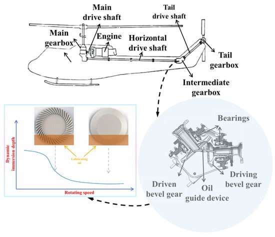
Figure 1.
Schematic diagram of splash lubrication for spiral bevel gears [2].
Current research on gear churning power loss primarily relies on numerical simulation, theoretical analysis, and experimental methods. Among these, numerical simulation develops more and more important effects in all aspects of gear lubrication encompassing methods such as the grid-based method, Moving Particle Semi-Implicit (MPS) method, Smoothed Particle Hydrodynamics (SPH), and Lattice Boltzmann Method (LBM). The grid-based method and MPS are more widely applied, whereas SPH and LBM are relatively less utilized.
The grid-based method has been extensively used in simulating spur gear oil stirring. For instance, Concli et al. [3] investigated the influence of gearbox pressure on oil-stirring power loss, concluding that a 50% pressure reduction could decrease losses by approximately 15%, with high-speed gears exhibiting greater sensitivity to pressure variations. Pau et al. [4] investigated windage power losses in orthogonal face gears using CFD simulations and experiments, highlighting that although friction and churning losses are well-studied, windage losses remain underexplored. Their results showed that windage torque predictions are sensitive to mesh quality and computational power, and simulation data correlated well with experimental measurements. For spiral bevel gears, Arisawa et al. [5] examined the impact of baffle drain port configurations on oil-stirring losses, reporting that a specific arrangement could reduce losses by 36%. Mastrone et al. [6] employed dynamic mesh technology to simulate oil-stirring losses and found that pressure loss dominated, with lubricant density exerting a greater influence than viscosity. SPH-based simulations remain relatively scarce. Legrady et al. [7] analyzed lubricant flow in a bevel gear reducer, focusing on bearing non-load power losses and exploring strategies to mitigate oil-stirring losses by reducing gear size. Liu et al. [8] simulated internal lubricant distribution in a spur gear system using SPH, demonstrating reliable flow predictions but encountering significant errors in oil-stirring torque, ranging from 55% to 82%. In the realm of LBM, Atencio et al. [9] investigated the effect of immersion depth on oil-stirring losses in spur gears, revealing an exponential increase in losses with rising oil levels. Gong et al. [10] compared LBM and SPH, concluding that while LBM exhibited higher accuracy, it required longer computational time. Additionally, their study indicated that doubling the oil level at high rotational speeds could result in a 9.4-fold increase in oil-stirring losses.
At present, theoretical models or semi-empirical formulas exist for analyzing oil-stirring power loss across various gear types. Theoretical research on spur gear oil-stirring power loss began relatively early. Seetharaman et al. [11,12] developed a power loss model for meshing spur gears, incorporating extrusion/pumping losses and gear-fluid interaction losses, identifying end-face and pumping losses as the primary contributors. Shore et al. [13] proposed an effective immersion depth model based on lubricant viscosity and gear speed, improving theoretical prediction accuracy. Arisawa et al. [14] formulated a hydrodynamic loss model that accounts for side airflow, air pumping, and lubricant acceleration. For bevel gears, Laruelle et al. [15] refined a dimensionless analysis model based on experimental corrections. Quiban et al. [16] analyzed torque variations in bevel gear oil-stirring experiments and introduced a dynamic immersion depth model to enhance prediction accuracy. Dai et al. [17] developed a power loss model incorporating both oil-stirring and aerodynamic effects, accounting for immersion depth variations induced by gear rotation. Additionally, Zhu et al. [18] proposed an oil-stirring power loss model for face gears based on boundary layer theory, addressing a research gap in this field. Further studies have explored low and negative oil levels in spur gears. Building on prior research, Jia et al. [19] refined the spur gear power loss model by incorporating losses due to lubricant acceleration in gear gaps and additional losses caused by centrifugal lubricant ejection. They further quantified the contribution of different loss mechanisms. To address the challenge of modeling churning losses in shrouded gears, Qian et al. [20] proposed a hybrid data- and physics-driven model. By simplifying the Navier–Stokes equations and integrating machine learning optimization, they developed a churning loss coefficients model (CLCM) with high generalization capability, achieving over 93% prediction accuracy in complex planetary gear systems. A numerical study by Teamah et al. [21] analyzed thermal losses in an internal gear train immersed in an oil-air mixture within a rotating casing. Using KISSsys and KISSsoft 2022, they quantified churning, meshing, and bearing losses under varying speeds, torques, and oil levels, with predictions showing a maximum 9.3% deviation from experimental data. Their results highlighted the sensitivity of churning losses to oil level and the positive effect of casing rotation on heat dissipation efficiency.
Numerous researchers have conducted detailed experimental studies on gear oil-stirring behavior, with most experiments focusing on spur and helical gears. To analyze the effect of dynamic flight attitudes on lubrication and energy loss in helicopter gear systems, Hu et al. [22] developed a 3D CFD model of a spiral bevel gearbox and validated it experimentally. Their results revealed how turning direction, rotational speed, circling attitude, and acceleration influence oil distribution, flow through guide holes, and churning losses. Quiban et al. [23] found that when the non-dimensional oil level is between 0.3 and 0.6, the gear torque variation aligns with oil-stirring theory. For oil levels below 0, aerodynamic drag dominates, while for levels between 0 and 0.2, both oil-stirring and aerodynamic drag effects coexist. Handschuh et al. [24] investigated the influence of gear module, helix angle, and oil temperature on oil-stirring losses, revealing that aerodynamic drag on the gear teeth becomes significant at high rotational speeds. Dai et al. [25] conducted experimental and analytical investigations on no-load power losses arising from windage and churning behaviors in rotating parts such as disks, spur gears, straight bevel gears, and orthogonal face gears. Their results demonstrated that cross-axis gears generate higher no-load losses compared to parallel-axis gears or disks, and two proposed analytical methods showed good agreement with experimental data, highlighting the significant impact of gear teeth on both windage and churning effects. Qian et al. [26] analyzed the effects of gear shrouds on heat dissipation and oil-stirring losses, considering both axial and radial clearances. Lu et al. [27,28] examined the non-load power losses due to splash lubrication in helicopter intermediate gearboxes, concluding that under normal operating conditions, the oil-stirring power loss of meshing bevel gears accounts for approximately 1.93% of input power. They further identified optimal gear speeds (3000–5000 rpm) and immersion depths (17–26 mm) that balance lubrication performance and power loss. Additionally, Chen et al. [29] studied oil-stirring losses under inclined conditions, showing that reducing the distance between the gear and the oil sump effectively lowers power loss. Hildebrand et al. [30] investigated the influence of circumferential speed and immersion depth on oil flow and no-load power loss in a dip-lubricated single-stage gearbox through numerical, experimental, and analytical methods. Their findings showed that wetted gear surface and gear loss torque correlate strongly with circumferential speed, with numerical and experimental results aligning well and revealing the limitations of analytical predictions, particularly at low speeds. Polly et al. [31] conducted a series of experimental investigations on spur gears, disks, and helical gears. Their results showed that when the oil immersion depth exceeded half the height of the gear, the viscosity of the lubricating oil significantly influenced gear torque. Compared to disks, spur gears exhibited 30% to 70% higher power losses, highlighting the substantial impact of gear teeth on oil churning losses. Furthermore, under identical oil levels, helical gears demonstrated lower oil churning losses compared to spur gears. Neurouth et al. [32] experimentally investigated the oil churning power loss of spur gears and helical gears under various operating conditions. To minimize the axial clearance of the gears, they introduced a movable wall. The results demonstrated that reducing the gap between the gears and the axial wall effectively decreased power loss. While reducing the gap on one side also contributed to power loss reduction, the effect was less pronounced compared to reducing the gap on both sides.
Predicting the churning losses for an isolated spiral bevel gear serves as the foundation for predicting those of a gear pair. Moreover, determining the dynamic immersion depth is essential for accurately predicting the churning losses of a single gear. Therefore, to achieve a more accurate theoretical prediction of the churning power loss for a spiral bevel gear submerged in oil, this study utilizes the practical dynamic immersion depth instead of the static depth value to better represent the actual churning behavior of the bevel gear, especially concerning churning losses. To this end, the paper adopts image recognition techniques to estimate the average dynamic immersion depths of both the front and back faces of the bevel gear. The characteristics of the distributed flow field of petroleum obtained through computational fluid dynamics (CFD) simulation were experimentally validated to ensure their accuracy and reliability. Additionally, the calculated dynamic immersion depths and numerical churning losses are compared with theoretical predictions to evaluate their consistency.
2. Churning Drag Torque Formulas
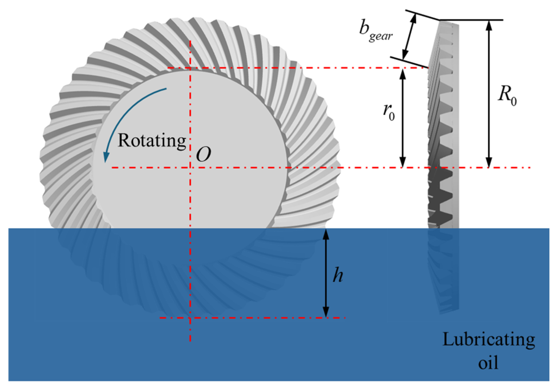
For the spiral bevel gear under splash lubrication condition (see Figure 2), Laruelle et al. [15] and Dai et al. [17,18] established theoretical prediction methods for the associated churning power losses, by introducing the dynamic oil level instead of the static oil level. The power loss is the product of the gear rotational speed n and the drag torque Tch, as:
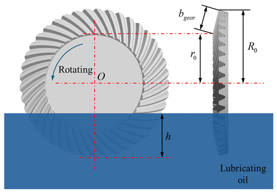
Figure 2.
Main parameters for a splash-lubricated spiral bevel gear.
The drag torque, Tch, acting on the bevel gear further falls into the axial torque on the toe/heel faces, Tf, the circumferential torque, Tp, on the peripheral contact area, and the torque between the teeth, Trf:
Based on Dai et al. [17,18], the circumferential torque, Tp, on the peripheral contact area is expressed as follows:
where μoil and ρoil are the oil viscosity and density, respectively. bgear is the teeth width, R0 is the outer radius of the bevel gear at the heel, () is the dimensionless oil level for the gear at the heel, and h represents the submergence value of the gear at the heel under the oil free surface.
Using the principle of boundary theory and the theoretical method by Seetharaman et al. [11,12] and Dai et al. [17,18], the axial torque on the toe/heel faces Tf, considering the flow regime of laminar flow () or turbulent flow ().
with
As for the torque between the teeth Trf, this physical quantity is negligibly small, calculated from the creeping flow analysis of Seetharaman et al. [9,10]. For more details refer to Seetharaman et al. [11,12] and Dai et al. [17,18].
Coming from the dynamic oil level instead of the static oil level proposed by Quiban et al. [16] and Dai et al. [17,18], the dynamic oil level is the piecewise function of the Froude number Fr* (, g is the gravitational acceleration.), and for the oil flow, the intermediate curve of the oil level is a straight line by substituting dynamic level for the above static oil level:
3. Numerical Simulation and Experimental Verification
3.1. Basic Equations
Due to the improved ability to handle highly stressed and rotating flows, the RNG turbulence model is well-justified for the numerical simulation of oil churning in spiral bevel gears. Given that gear churning involves rapid variations in fluid velocity and pressure due to gear rotation and oil splash, the RNG turbulence model effectively captures the energy dissipation and turbulence intensity, leading to a more precise estimation of power losses and lubricant distribution. Therefore, the RNG turbulence model is suitable for simulating the complex hydrodynamic phenomena in spiral bevel gear lubrication. The mass conservation equation (continuity equation) and momentum conservation equation for the RNG turbulence model in the numerical simulation of oil churning in spiral bevel gears can be expressed as follows:
where is the pressure and is the fluid density. is the effective viscosity, which includes contributions from both molecular viscosity and turbulence viscosity. represents the velocity vector of the fluid flow, represents external forces, and is the gravitational acceleration.
3.2. Geometry and CFD Model
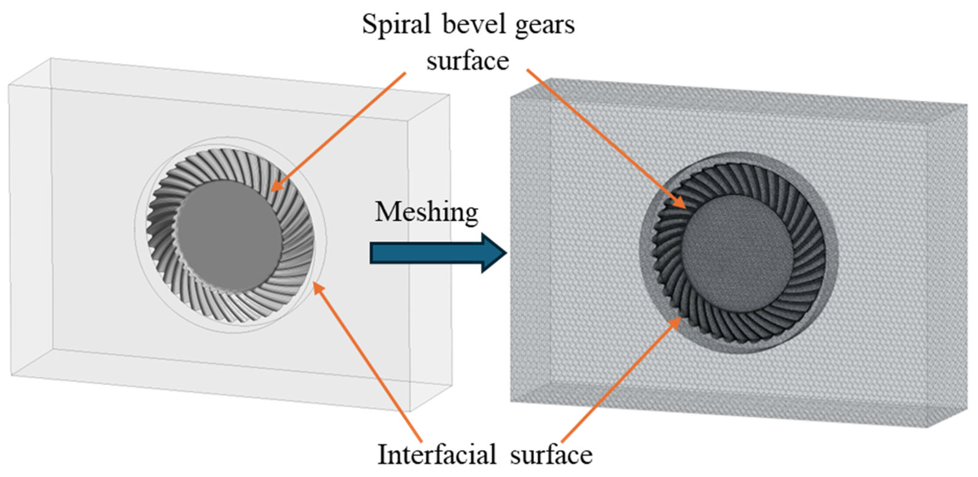
This study conducts a numerical investigation of the churning behavior of the spiral bevel gear using the commercial CFD software ANSYS 2022R1 Fluent. To simplify the numerical model and reduce computational load, non-research components such as rolling bearings and shafts are omitted, as illustrated in Figure 3. The rotational motion of the spiral bevel gear is reproduced using the sliding mesh method, which consists of a moving mesh surrounding the surface of the spiral bevel gear and a static mesh connected through an interface. ANSYS Mesh is employed to generate an unstructured mesh for both moving and static domains, where the moving mesh utilizes tetrahedral elements, while the static mesh adopts hexahedral elements. To enhance the prediction accuracy of the no-load gear resistance torque and capture the evolution of the lubricating oil flow field, a localized refinement is applied to the gear surface mesh, with the refined mesh size approximately one-tenth of the tooth height. Additionally, the size of the moving mesh is designed to be equal to or closely matching that of the static mesh. In the grid independence test, three distinct grids were configured: 2.4 million, 3.2 million, and 4.0 million. The results of the 3.2 million grid calculation and the 4.0 million grid calculation were found to be largely congruent. In order to enhance the computational efficiency and ensure the progression of the simulation calculation, the total number of grid cells in the final numerical model is 3.2 million.
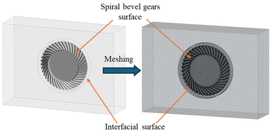
Figure 3.
Computational domain and grid model.
For other numerical simulation parameters, the rotational speed of the spiral bevel gear is set to 3000 r/min, resulting in a fluid velocity, , reaching up to 25 m/s. Given that the minimum mesh size is 0.5 mm, the simulation employs a time step of s. A residual convergence criterion of is applied to all governing equations. The numerical simulation results indicate that, due to the combined effects of pressure and viscosity, the total resistance torque acting on the spiral bevel gear eventually stabilizes. When the gear’s resistance torque reaches a steady state, its fluctuation amplitude should not exceed 10% of the mean value. This mean value is then adopted as the numerical result and compared with the experimental data’s average value to analyze the corresponding flow field characteristics further.
3.3. Splash Lubrication Test Description
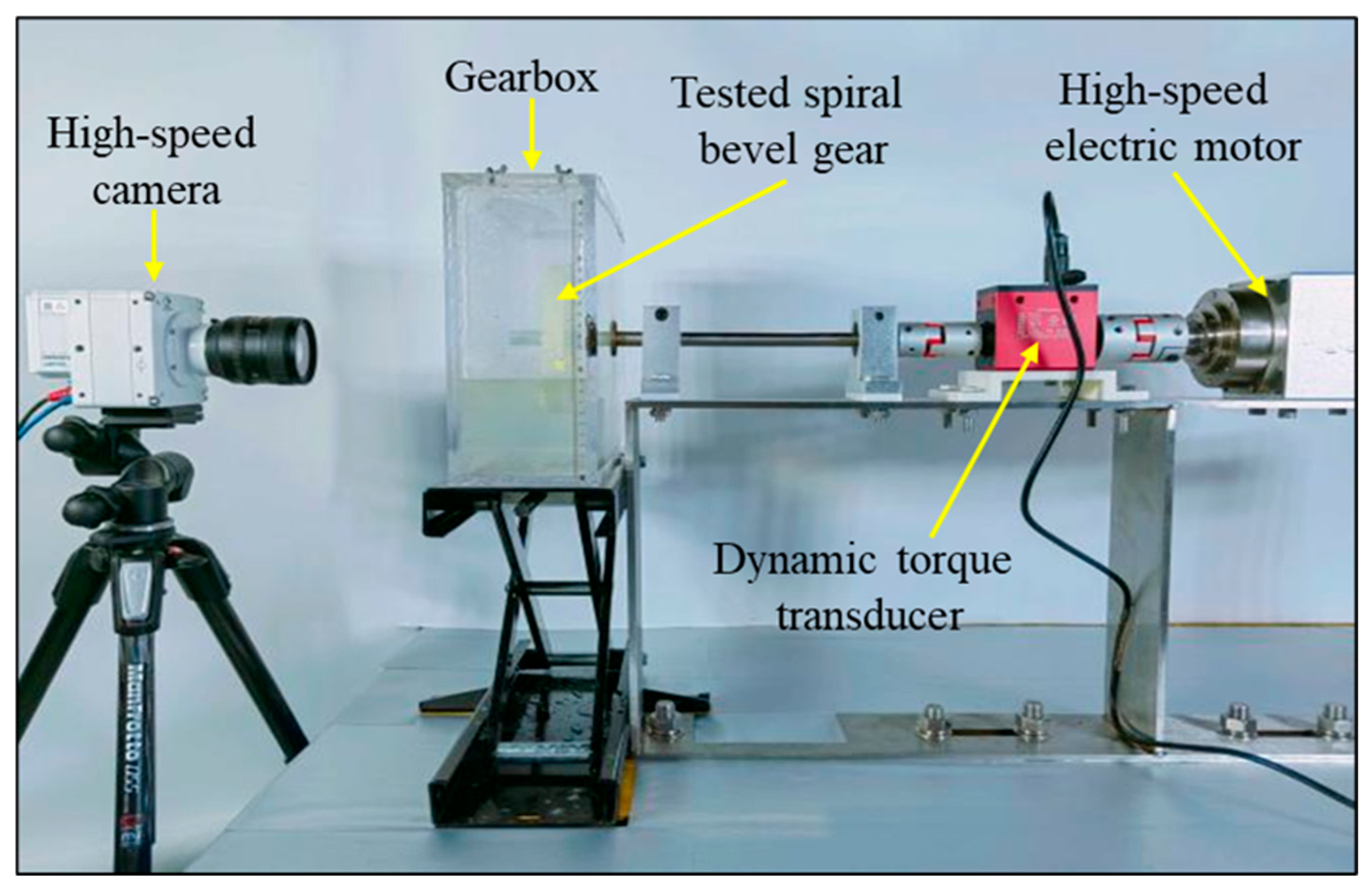
Zhu and Dai conducted splash lubrication experiments on spiral bevel gears using a specialized test rig [1], which comprises a high-speed motor, a torque sensor, and a gearbox equipped with 3D-printed spiral bevel gears. Compared to the metal gear manufactured using a flank milling method, the 3D-printed gear offers several advantages. First, 3D-printed gears eliminate the need for molds, enabling the rapid production of complex geometries with high precision. Second, this technology provides material versatility and cost efficiency, reducing both time and monetary investments. Lastly, these gears are not subjected to external loads. Consequently, this study utilized 3D-printed gears instead of metal gears manufactured using a flank milling method to investigate churning power losses. The spindle operates at a maximum rotational speed of 12,000 rpm and is fitted with a dynamic torque sensor with a precision of ±0.01 Nm. The gearbox is housed within a rectangular acrylic chamber (380 mm × 266 mm × 100 mm), enabling direct visual inspection and fluid flow visualization via high-speed cameras.
Figure 4 shows the experimental equipment. During the experiments, a separation method was employed to determine the net resistance torque by subtracting the resistance torque of the system without gears from that with gears. For each steady-state condition, the resistance torque and corresponding flow field variations were recorded. Table 1 presents the key parameters of the spiral bevel gear, including its outer diameter and gear width. The bevel gear rotates counterclockwise at a speed of r/min. For cleanliness purposes, water was used as a substitute for aviation lubricants during the experiments. The was preset from 0.3 to 0.6.

Figure 4.
Splash-lubricated spiral bevel gear test device.

Table 1.
Main parameters of spiral bevel gear.
4. Analysis and Verification
4.1. Flow Field Distribution
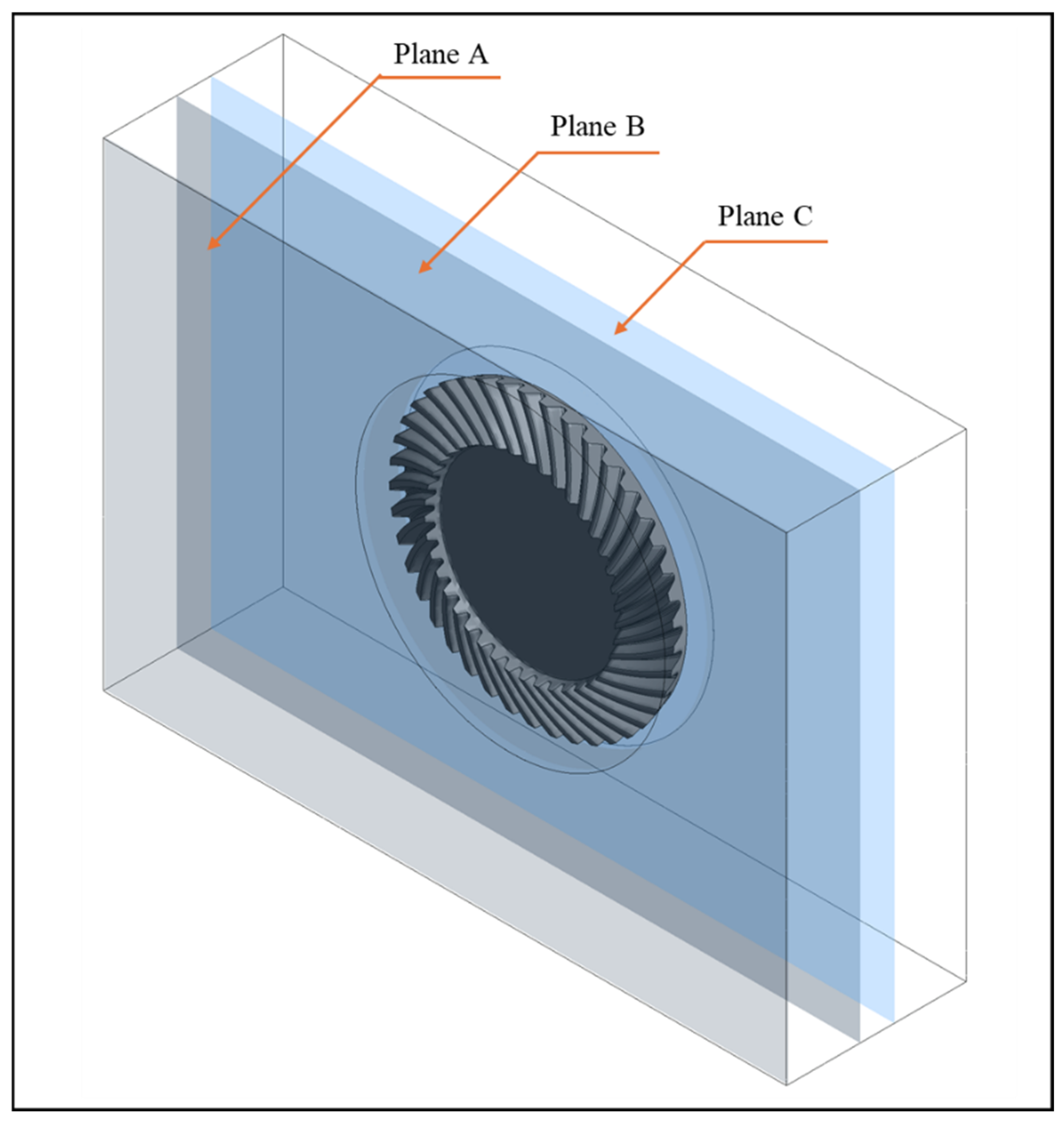
In this study, the rotational speed of the spiral bevel gear in both numerical simulations and experiments is set to 3000 r/min. To maintain consistency with the experimental conditions, water is also used as a substitute for aviation lubricant in the numerical simulations. The initial non-dimensional static oil level, , is preset to 0.3, 0.4, 0.5, and 0.6. To gain deeper insights into the flow field characteristics during the oil churning process of the spiral bevel gear, three relative reference planes within the numerical simulation fluid domain are analyzed, as illustrated in Figure 5. The axial planes A, B, and C coincide with the front-end face of the spiral bevel gearbox and the front- and rear-end faces of the spiral bevel gear, respectively.
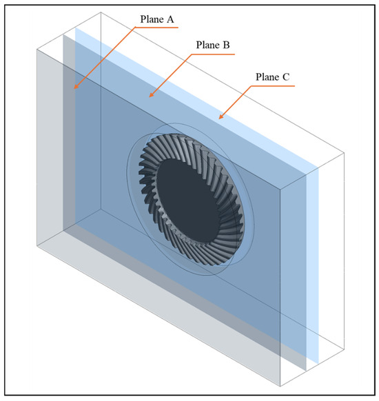
Figure 5.
Reference planes of computing domain.
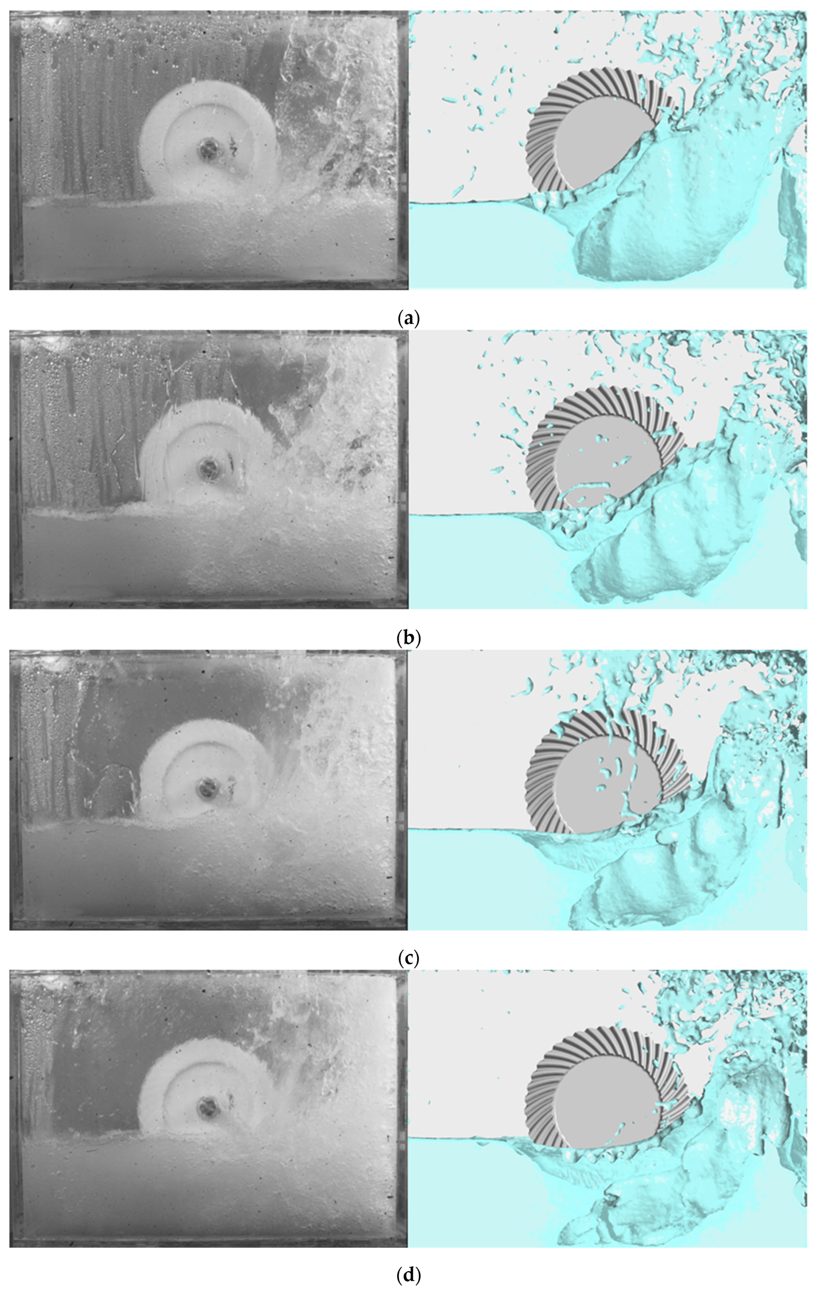
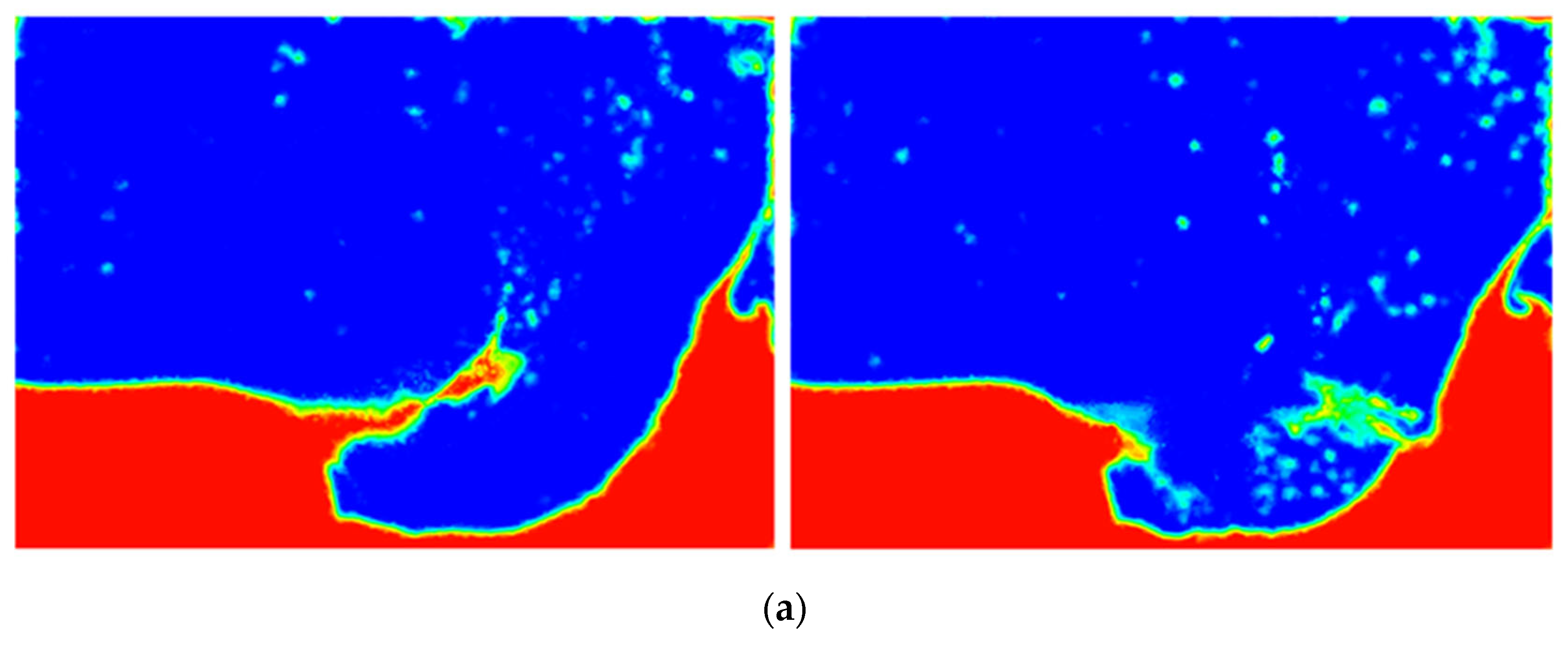
As illustrated in Figure 6, a comparative analysis is presented between experimental images captured by high-speed cameras and numerical simulation isosurface data of oil churning by the spiral bevel gear under different initial immersion depths. By comparing and analyzing the flow field distribution, the oil churning behavior can be summarized as follows. When the initial non-dimensional static oil level is low, the interaction between the spiral bevel gear and the fluid is insufficient, resulting in limited kinetic energy transfer from the gear to the fluid. Consequently, the liquid rapidly fragments upon agitation, forming fine oil droplets, as observed at . Conversely, when the initial non-dimensional static oil level is relatively high, the gear-fluid interaction becomes more intense, leading to substantial oil droplet and ligament formation. These structures are vigorously stirred into the air on the right side, reaching greater depths and velocities, even obscuring the transparent acrylic plate at the front, as exemplified by .
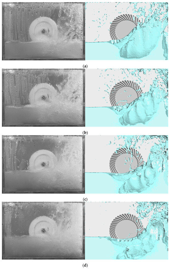
Figure 6.
Comparisons of experimental and numerical churning phenomenon: (a) ; (b) ; (c) ; (d) .
Furthermore, the flow field characteristics obtained from the numerical simulation exhibit a high degree of similarity to those recorded in the experiments, validating the reliability and effectiveness of numerical methods in investigating oil distribution within the spiral bevel gearbox.
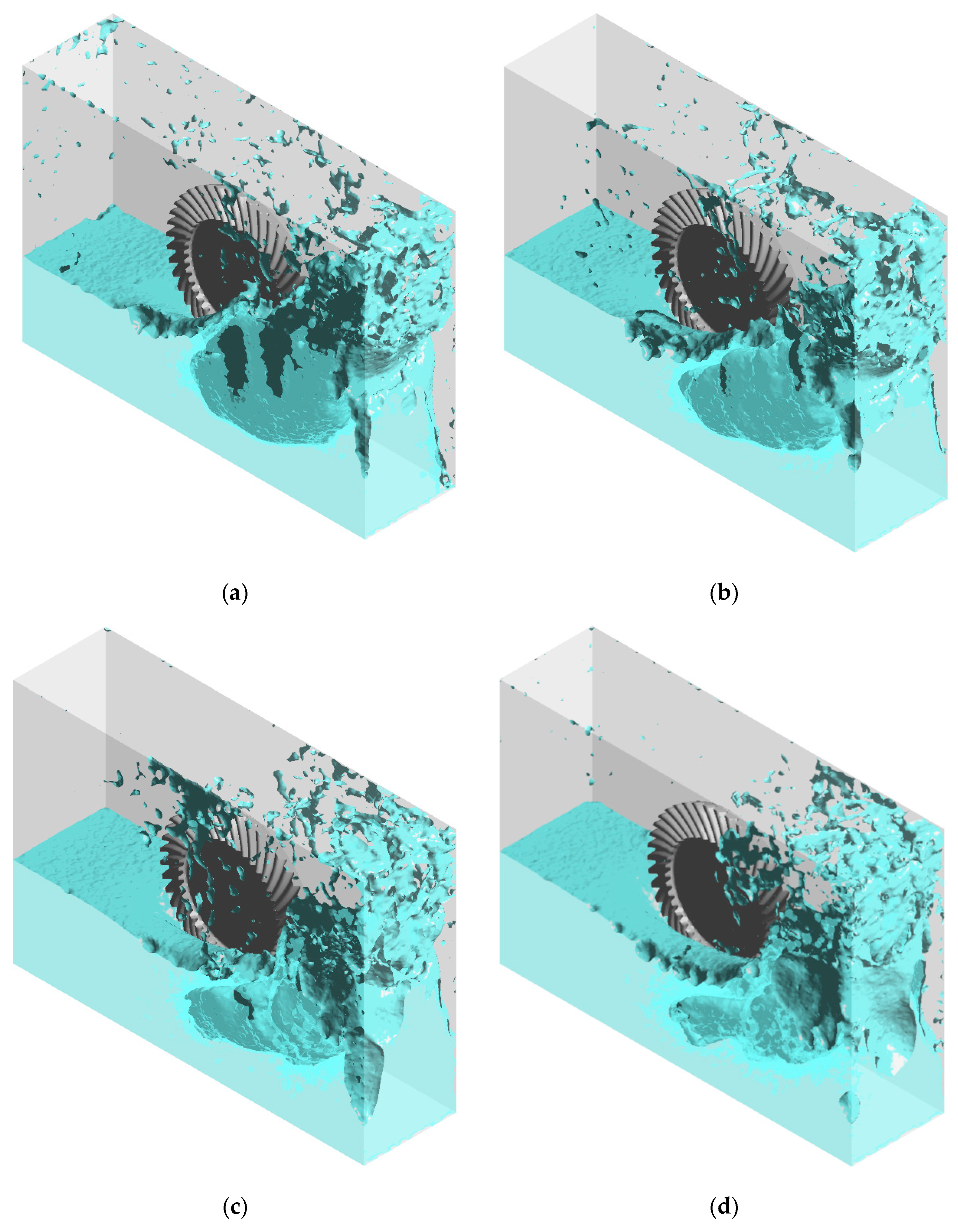
Figure 7 illustrates the isosurface representation of the flow field distribution in the numerical simulation of oil churning by the spiral bevel gear. Observing the overall flow field characteristics within the gearbox reveals that as the non-dimensional static oil level increases, the oil churning process becomes more pronounced, leading to a greater number of oil droplets and ligaments splashing toward the upper right corner of the gearbox. However, an examination of the volume fraction distribution on the front wall of the gearbox (Plane A) in Figure 8 indicates that even at , noticeable splashing occurs. This phenomenon arises because the total mass of oil in contact with the spiral bevel gear is relatively small at this depth, making it more susceptible to agitation and splashing. Nevertheless, the shallow immersion depth results in insufficient oil churning, leading to lower overall kinetic energy in the splashed liquid. Consequently, the liquid lacks the momentum to traverse the top of the spiral bevel gear and reach the opposite side of the gearbox, as shown in Figure 8a,b. As the initial immersion depth increases, the interaction between the spiral bevel gear and the liquid becomes more substantial, imparting greater kinetic energy to the splashed liquid. This enhanced momentum enables the liquid to fully traverse the top of the spiral bevel gear, as depicted in Figure 8c,d.

Figure 7.
Isometric view of isosurface of oil flow phenomenon: (a) ; (b) ; (c) ; (d) .

Figure 8.
Volume fraction distributions of spiral bevel gear in plane A: (a) ; (b) ; (c) ; (d) .
4.2. Practical Immersion Depth
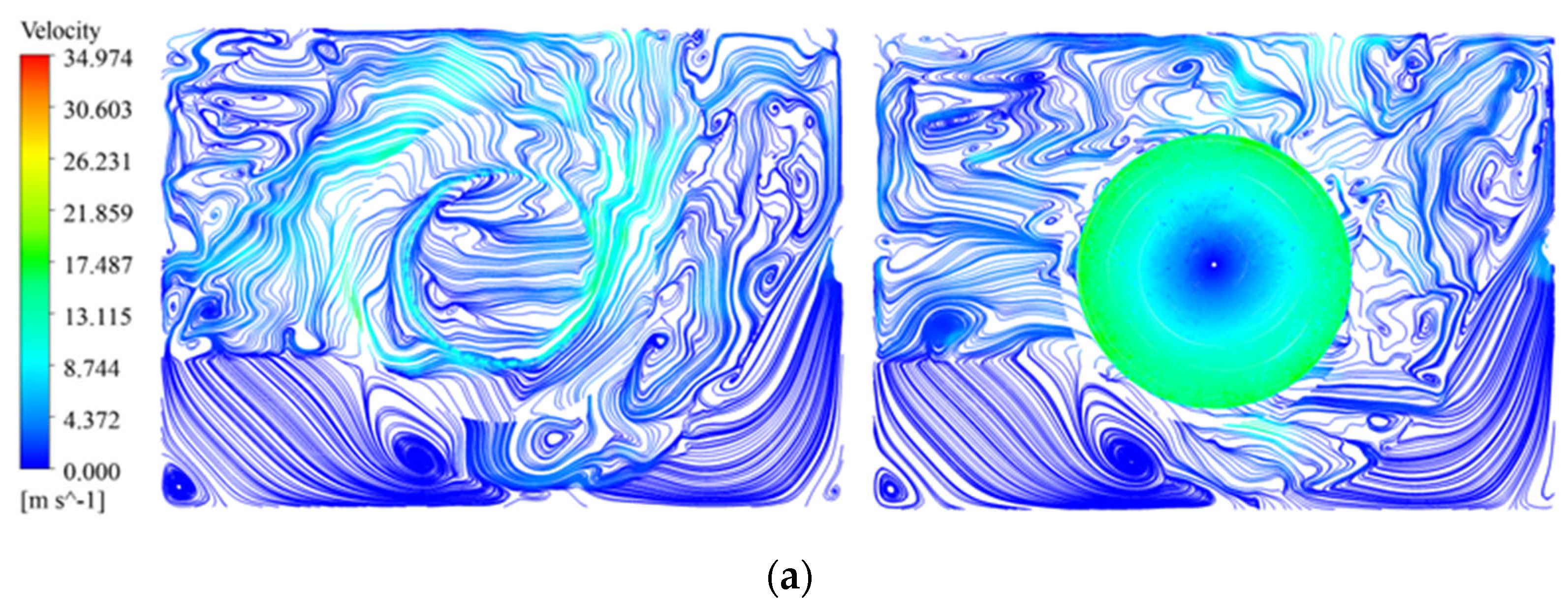
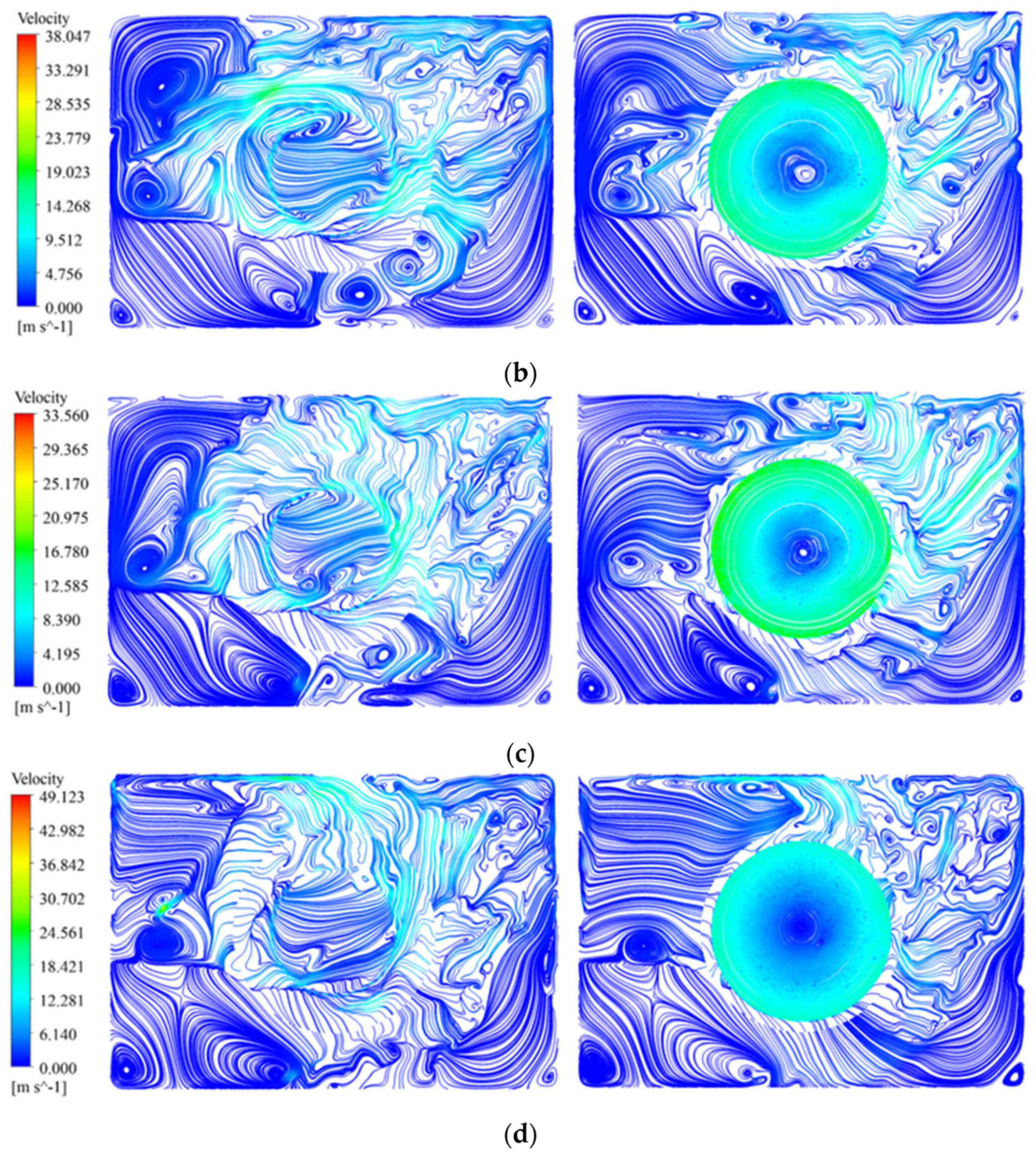
As shown in Figure 9, the streamlines on the front (Plane B) and rear (Plane C) end faces of the spiral bevel gear exhibit distinct flow characteristics. Due to the structural features of the spiral bevel gear, at the same rotational speed, the linear velocity at the tooth tip of the front-end face is lower than that at the tooth root of the rear-end face. This difference results in a greater velocity magnitude in the fluid near the rear-end face compared to the front-end face.


Figure 9.
Streamline distribution of spiral bevel gear in plane B (left) and plane C (right): (a) ; (b) ; (c) ; (d) .
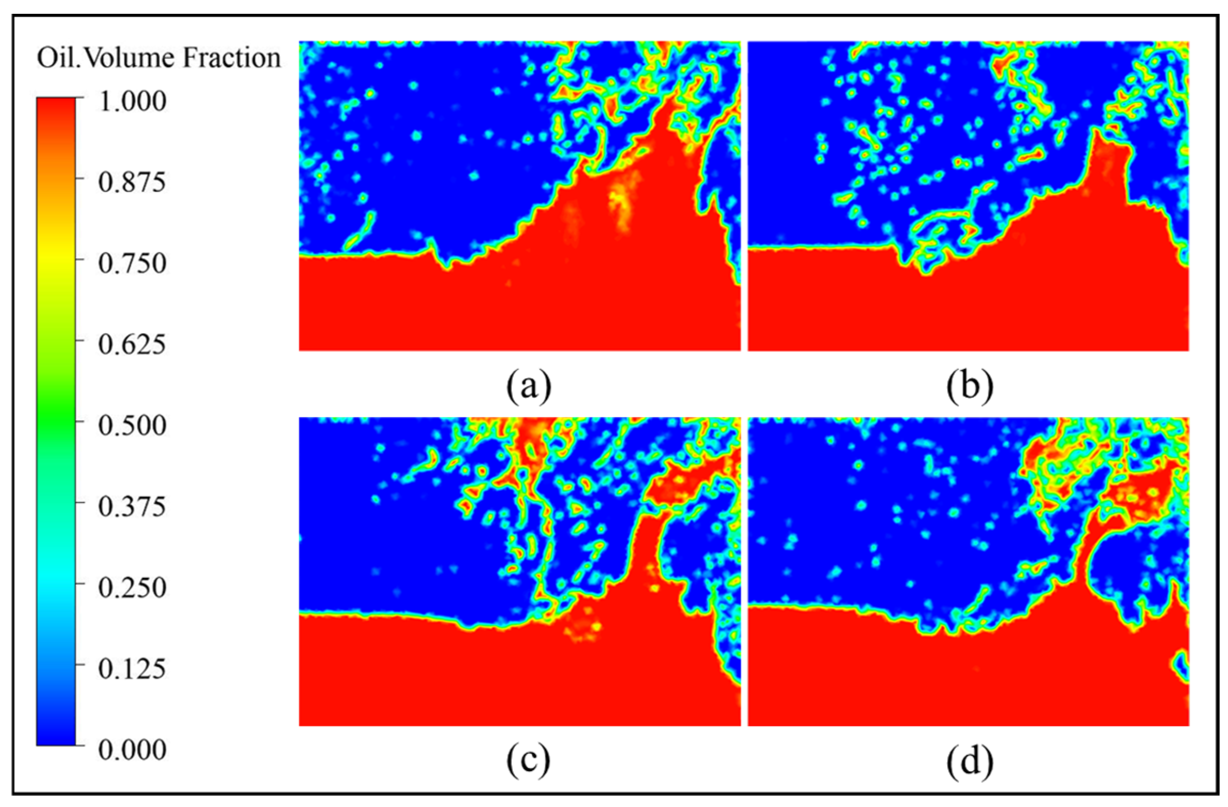
Although the fluid velocity induced by the churning effect at the rear-end face is higher, the smooth and flat surface of the rear-end face limits the interaction between the gear teeth and the fluid. Consequently, the overall volume of stirred liquid at the rear-end is smaller than that at the front-end, as illustrated in Figure 10.
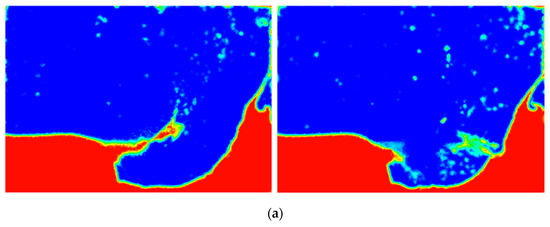
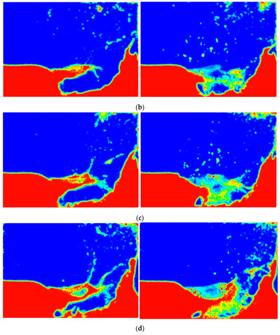
Figure 10.
Volume fraction distributions of spiral bevel gear in plane B (left) and plane C (right): (a) ; (b) ; (c) ; (d) .
By examining the oil volume fraction on the front and rear-end faces, a significant difference in the stirred oil volume fraction between the two surfaces can be observed. This discrepancy directly leads to an inconsistency in the practical immersion depth between the front and rear-end faces of the spiral bevel gear.
During the oil churning process of the spiral bevel gear, the practical oil immersion depth is influenced by both the free surface of the oil pool and the initial immersion depth. Image processing techniques can be utilized to determine the oil volume fraction in the radial cross-section of the gear, enabling a more precise calculation of the actual oil immersion depth. Figure 11 illustrates a schematic representation of the image processing method developed using OpenCV 4.8.0 for analyzing the oil volume fraction distribution in the outside diameter region of the spiral bevel gear. The proposed approach starts with pre-processing the volume fraction distribution images to remove interference from extraneous objects, ensuring that only the critical region is extracted. This step improves computational efficiency.
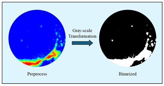
Figure 11.
Image processing of volume fraction.
Subsequently, grayscale transformation and binarization are performed. In the grayscale transformation, the red, green, and blue (RGB) values of each pixel in the original image are averaged to generate a grayscale representation. Binarization is then carried out by applying a threshold to the grayscale image: pixels with values above the threshold are set to white (255), while those below the threshold are set to black (0). Finally, background noise is eliminated to accurately extract oil droplet pixel information. The total number of white pixels in the processed image is subsequently calculated to estimate the oil volume fraction and determine the equivalent immersion depth.
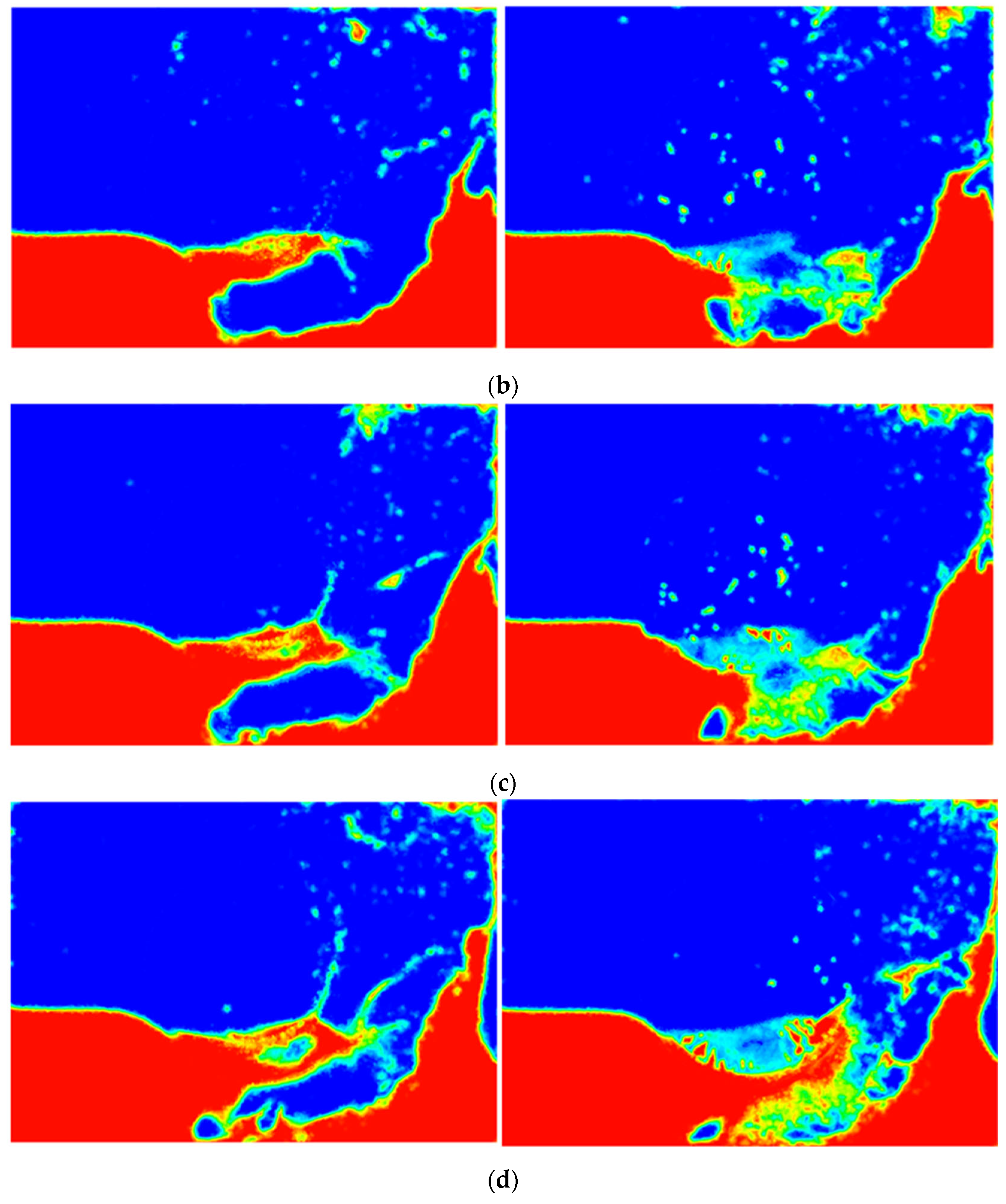
Figure 12 presents the practical oil volume fraction distribution of the spiral bevel gear’s oil churning behavior under different initial immersion depths. The left images correspond to the front-end of the spiral bevel gear (Plane B), while the right images represent the rear-end (Plane C). A comparative analysis reveals that when the initial non-dimensional static oil level is relatively low, such as , there is a substantial difference in the practical immersion depth between the front and rear-end faces. However, as the initial non-dimensional static oil level increases, the immersion depths of the front and rear-end faces gradually converge. This phenomenon occurs because a greater initial immersion depth enhances the interaction between the spiral bevel gear and the lubricating oil. The stirred oil gains sufficient kinetic energy, and due to the viscous effect of the fluid, it induces rotational churning of the oil at the rear-end of the gear, promoting overall oil circulation and splashing within the gear’s vicinity.
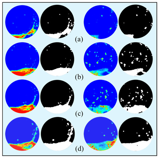
Figure 12.
Image processing of volume fraction of spiral bevel gear in plane B (left) and plane C (right): (a) ; (b) ; (c) ; (d) .
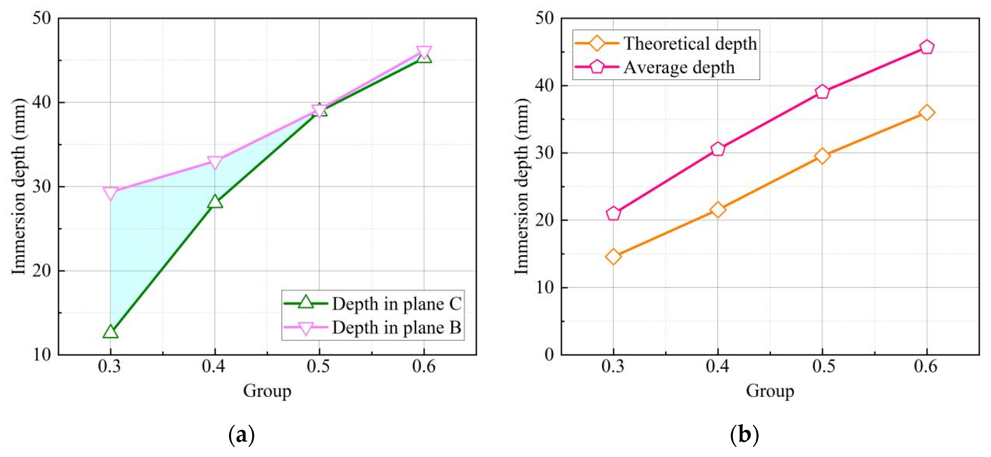
Figure 13a shows the practical immersion depths of the front- and rear-faces of the spiral bevel gear obtained by statistical calculations using image processing techniques. The results indicate that as the initial immersion depth increases, the difference in oil immersion depth between the front- and rear-end faces decreases. To further analyze the trend, the practical immersion depths of both end faces were averaged, as shown in Figure 13b. The averaged depth of immersion closely matches the theoretical depth calculated using Equation (6), demonstrating the overall stability of the trend.

Figure 13.
Immersion depth with different initial conditions: (a) numerical immersion depth; (b) theoretical immersion depth.
4.3. No-Load Resisting Torque
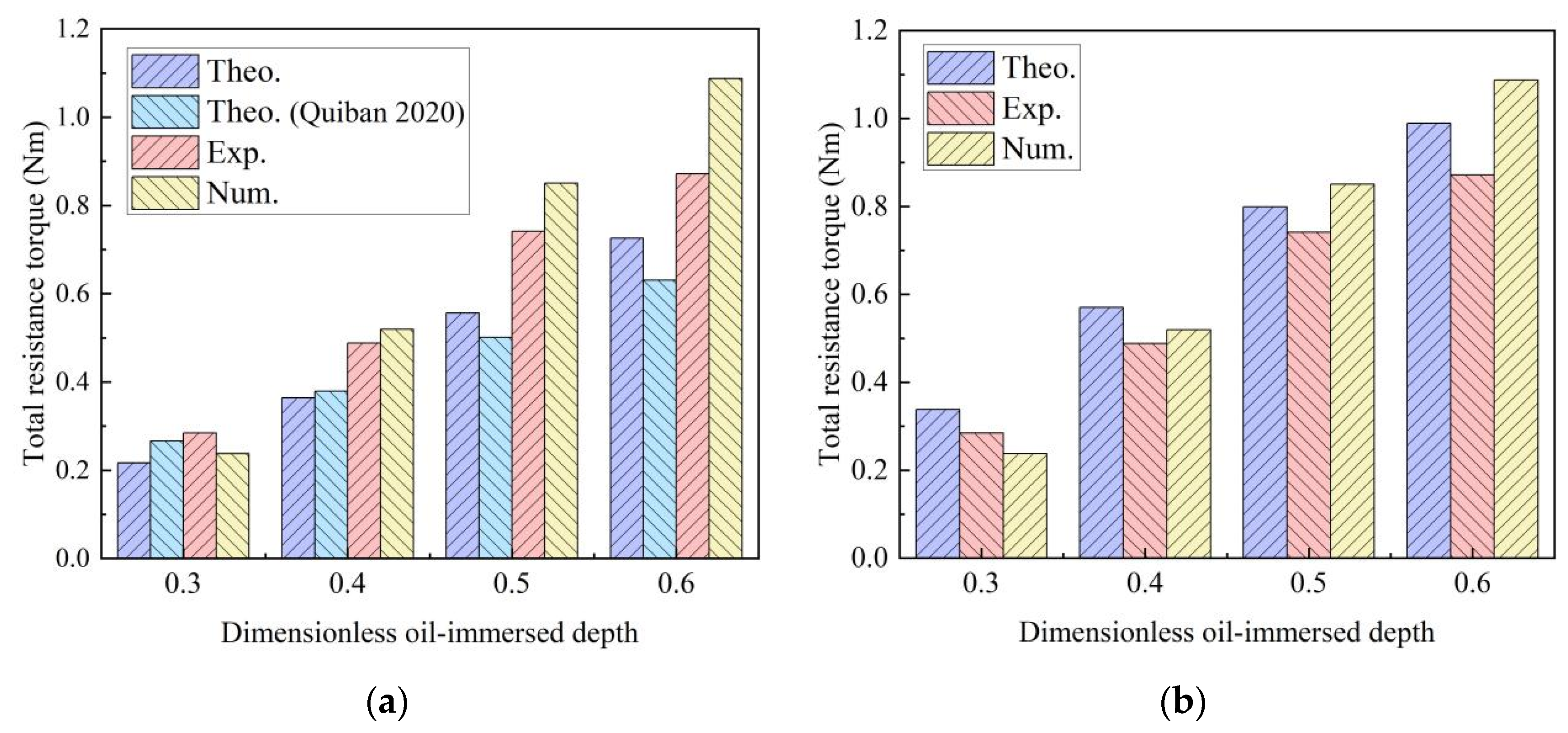
In the measurement of resistance torque, three tests were conducted for the same operating conditions. The resistance torque under steady-state conditions was averaged to determine the torque at specific oil levels. This study compared gear resistance torque under oil immersion lubrication with numerical simulations and theoretical calculations, as shown in Figure 14a, the theoretical non-load resistance torque is calculated by Equations (1)–(5). At a rotational speed of approximately 3000 rpm, dimensionless oil immersion depths of 0.3, 0.4, 0.5, and 0.6 were tested. Results indicate that non-load resistance torque increases with deeper oil immersion. The theoretical predictions showed average errors of 22.82% and 22.23% compared to experimental data and Quiban’s model, respectively [16]. The maximum error for the theoretical method (25.48%) occurred at an oil level of 0.4, while Quiban’s model had its largest error (32.40%) at the 0.5 oil level. Although both theoretical models showed similar average errors, Quiban’s model exhibited greater maximum deviations. In contrast, numerical simulations agreed better with experiments, showing an average error of 15.63% and a maximum error of 24.73% at 0.6 oil level. These findings highlight the need for improving theoretical methods, particularly in estimating dynamic oil immersion depth.
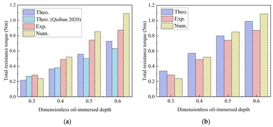
Figure 14.
Churning drag torques of spiral bevel gear with different methods [16]: (a) before image processing; (b) after image processing.
To address this, practical oil immersion depths obtained through image processing replaced theoretical dynamic depth estimates. The improved theoretical, numerical, and experimental resistance torques are shown in Figure 14b. The average error of the theoretical method decreased from 22.82% to 14.22%, with the maximum error (18.78%) occurring at the 0.3 oil level. Compared to numerical results, the improved theoretical method achieved smaller average errors. This demonstrates that combining dynamic immersion depth obtained by image processing with theoretical calculations enhances the prediction accuracy of churning resistance torque in spiral bevel gears.
5. Conclusions
This study investigates the relationship between the oil distribution characteristics and churning Loss losses of splash-lubricated spiral bevel gears based on practical immersion depth. The main conclusions are as follows:
- A significant difference in practical oil immersion depth was observed between the front and rear-end faces of the spiral bevel gear. This disparity was more pronounced at lower initial oil levels, whereas at higher oil levels, the immersion depths of both end faces tended to converge.
- The application of image processing technology facilitated the quantitative analysis of oil distribution around the spiral bevel gear. Statistical evaluation of the oil volume fraction at the front and rear-end faces showed good agreement between the measured average immersion depth and the theoretically calculated values, thereby validating the effectiveness of this approach in assessing churning behavior.
- Experimental data collected under various initial oil levels validated the accuracy of the developed gas–liquid two-phase flow model and the computational fluid dynamics (CFD) simulations. The results demonstrate that the proposed theoretical model effectively predicts the churning losses of spiral bevel gears.
- Experimental measurements demonstrated that as the oil level increases, the churning contributions from both end faces become more balanced. A quantitative correlation between practical immersion depth and churning power loss was established, offering valuable insights for optimizing the lubrication design of spiral bevel gears.
However, the churning losses of a gear pair encompass the power losses from both the driving and driven gears, as well as the pumping losses caused by gear engagement. We are currently conducting further research to predict the churning power losses of a spiral bevel gear pair under splash lubrication, based on the proposed dynamic immersion depth model and the churning losses model for individual gears.
Author Contributions
Conceptualization, Y.D. and X.Z.; methodology, X.H., C.Y. and J.Z.; software, X.H., C.Y. and J.Z.; validation, Y.D. and X.Z.; formal analysis, X.Z.; investigation, X.H., C.Y. and J.Z.; resources, Y.D.; data curation, X.H., C.Y. and J.Z.; writing—original draft preparation, X.Z.; writing—review and editing, X.H., C.Y. and J.Z.; visualization, X.Z.; supervision, X.Z. and Y.D.; project administration, Y.D.; funding acquisition, Y.D. All authors have read and agreed to the published version of the manuscript.
Funding
This work was supported by the National Natural Science Foundation of China (Grant No. 52475078 and 52305081), the National Defense Pre-Research Foundation of China (Grant No. KY-1044-2023-0451), and the Science and Technology Innovation Program of Hunan Province (Grant number 2024RC1001).
Institutional Review Board Statement
Not applicable.
Informed Consent Statement
Not applicable.
Data Availability Statement
The original contributions presented in the study are included in the article, further inquiries can be directed to the corresponding author.
Conflicts of Interest
Author Jianfeng Zhong was employed by the company Hunan Aviation Powerplant Research Institute, Aero Engine Corporation of China (AECC). The remaining authors declare that the research was conducted in the absence of any commercial or financial relationships that could be construed as a potential conflict of interest.
Abbreviations
| Teeth width, mm | |
| Dimensionless churning resistance torque coefficient on the face | |
| Froude number | |
| Acceleration of gravity, m/s | |
| Oil-immersed depth, mm | |
| Churning power losses, W | |
| Outside radius, mm | |
| Outer radius of the bevel gear, mm | |
| Drag torque, Nm | |
| Circumferential torque, Nm | |
| Axial torque on the toe/heel faces, Nm | |
| Torque between the teeth, Nm | |
| Oil viscosity, Pa s | |
| Oil density, kg/m3 | |
| Dimensionless oil level | |
| Dynamic oil level | |
| Static oil level |
References
- Liu, H.; Liu, H.; Zhu, C.; Parker, R.G. Effects of lubrication on gear performance: A review. Mech. Mach. Theory 2020, 145, 103701. [Google Scholar] [CrossRef]
- Dai, Y.; Yang, C.; Zhang, R.; Zhu, X. A unified analytical model to calculate no-load power losses for the coexistence of windage-churning phenomenon for spiral bevel gears. Eur. Phys. J. Plus 2024, 139, 255. [Google Scholar] [CrossRef]
- Concli, F.; Gorla, C.; Rosa, F.; Conrado, E. Effect of the static pressure on the power dissipation of gearboxes. Lubr. Sci. 2019, 31, 347–355. [Google Scholar] [CrossRef]
- Pau, T.-D.; Korka, Z.-I.; Nedelcu, D.; Hrimiuc, C. Assessing the Meshing for Windage Power Loss Simulations of an Orthogonal Face Gear. Machines 2025, 13, 341. [Google Scholar] [CrossRef]
- Arisawa, H.; Nishimura, M.; Imai, H.; Goi, T. Computational fluid dynamics simulations and experiments for reduction of oil churning loss and windage loss in aeroengine transmission gears. J. Eng. Gas Turbines Power 2014, 136, 092604. [Google Scholar] [CrossRef]
- Mastrone, M.; Concli, F. Power losses of spiral bevel gears: An analysis based on computational fluid dynamics. Front. Mech. Eng. 2021, 7, 655266. [Google Scholar] [CrossRef]
- Legrady, B.; Taesch, M.; Tschirschnitz, G.; Mieth, C.F. Prediction of churning losses in an industrial gear box with spiral bevel gears using the smoothed particle hydrodynamic method. Forsch. Im Ingenieurwesen 2021, 86, 379–388. [Google Scholar] [CrossRef]
- Liu, H.; Arfaoui, G.; Stanic, M.; Montigny, L.; Jurkschat, T.; Lohner, T.; Stahl, K. Numerical modelling of oil distribution and churning gear power losses of gearboxes by smoothed particle hydrodynamics. Proc. Inst. Mech. Eng. Part J J. Eng. Tribol. 2019, 233, 74–86. [Google Scholar] [CrossRef]
- Atencio, B.; Yao, H.; Chernoray, V. Experiments and Lattice-Boltzmann simulation of flow in a vertically aligned gearbox. J. Tribol. 2023, 145, 114103. [Google Scholar] [CrossRef]
- Gong, R.; Gong, Q.; Che, H.; Zhang, Z. Numerical investigation on churning loss torque and oil distribution of reducer based on lattice boltzmann method. Tribol. Trans. 2021, 64, 968–979. [Google Scholar] [CrossRef]
- Seetharaman, S.; Kahraman, A. Load-independent spin power losses of a spur gear pair: Model formulation. J. Tribol. 2009, 131, 022201. [Google Scholar] [CrossRef]
- Seetharaman, S.; Kahraman, A.; Moorhead, M.D.; Petry-Johnson, T.T. Oil churning power losses of a gear pair: Experiments and model validation. J. Tribol. 2009, 131, 022202. [Google Scholar] [CrossRef]
- Shore, J.F.; Kolekar, A.S.; Ren, N.; Kadiric, A. An investigation into the influence of viscosity on gear churning losses by considering the effective immersion depth. Tribol. Trans. 2023, 66, 906–919. [Google Scholar] [CrossRef]
- Arisawa, H.; Tanaka, M.; Hashimoto, H.; Goi, T.; Banno, T.; Akahori, H. Fluid dynamic loss model with wide applicability for aeroengine transmission gears. J. Eng. Gas Turbines Power 2024, 146, 051001. [Google Scholar] [CrossRef]
- Laruelle, S.; Fossier, C.; Changenet, C.; Ville, F.; Koechlin, S. Experimental investigations and analysis on churning losses of splash lubricated spiral bevel gears. Mech. Ind. 2017, 18, 412. [Google Scholar] [CrossRef]
- Quiban, R.; Changenet, C.; Marchesse, Y.; Ville, F.; Belmonte, J. Churning losses of spiral bevel gears at high rotational speed. Proc. Inst. Mech. Eng. Part J J. Eng. Tribol. 2020, 234, 172–182. [Google Scholar] [CrossRef]
- Dai, Y.; Ma, F.; Zhu, X.; Ouyang, B. Development of an analytical model to estimate the churning power losses of a spiral bevel gear. Tribol. Int. 2020, 151, 106536. [Google Scholar] [CrossRef]
- Zhu, X.; Dai, Y. Development of an analytical model to predict the churning power losses of an orthogonal face gear. Eng. Sci. Technol. Int. J. 2023, 41, 101383. [Google Scholar] [CrossRef]
- Jia, F.; Wang, B.; Fu, Y. A novel prediction model for churning power loss of spur gear. Lubr. Sci. 2024, 36, 645–655. [Google Scholar] [CrossRef]
- Qian, X.; Yin, S.; Sun, T.; Yang, K.; Chen, S.; Chu, Y.; Zhang, Y.; Yu, X.; Liu, C. Churning loss modeling for shroud gears driven by physics-data hybrids. Mech. Syst. Signal Process. 2025, 229, 112532. [Google Scholar] [CrossRef]
- Teamah, A.M.; Hamed, M.S. Numerical investigation of thermal losses within an internal gear train submerged in a multiphase flow and enclosed in a rotating casing. Int. J. Thermofluids 2022, 15, 100188. [Google Scholar] [CrossRef]
- Hu, X.; Wang, A.; Li, P.; Wang, J. Influence of dynamic attitudes on oil supply for bearings and churning power losses in a splash lubricated spiral bevel gearbox. Tribol. Int. 2021, 159, 106951. [Google Scholar] [CrossRef]
- Quiban, R.; Changenet, C.; Marchesse, Y.; Ville, F. Experimental investigations about the power loss transition between churning and windage for spur gears. J. Tribol. 2021, 143, 024501. [Google Scholar] [CrossRef]
- Handschuh, M.; Guner, A.; Kahraman, A. An experimental investigation of windage and oil churning power losses of gears and discs. Proc. Inst. Mech. Eng. Part J J. Eng. Tribol. 2023, 237, 163–177. [Google Scholar] [CrossRef]
- Dai, Y.; Yang, C.; Liu, H.; Zhu, X. Analytical and Experimental Investigation of Windage–Churning Behavior in Spur, Bevel, and Face Gears. Appl. Sci. 2024, 14, 7603. [Google Scholar] [CrossRef]
- Qian, X.; Zhang, S.; Yang, K.; Yan, W.; Chen, S.; Zhang, Y.; Liu, C. Strategy of directional oil transport for splash lubrication systems. Int. J. Mech. Sci. 2024, 269, 109059. [Google Scholar] [CrossRef]
- Lu, F.; Wang, M.; Bao, H.; Huang, W.; Zhu, R. Churning power loss of the intermediate gearbox in a helicopter under splash lubrication. Proc. Inst. Mech. Eng. Part J J. Eng. Tribol. 2022, 236, 49–58. [Google Scholar] [CrossRef]
- Lu, F.; Cao, X.; Bao, H.; Zhu, R. Nonlinear tribo-dynamic model of helicopter mid-reducer system under light loss of lubrication. J. Mech. Sci. Technol. 2022, 36, 5327–5339. [Google Scholar] [CrossRef]
- Chen, S.; Matsumoto, S. Influence of relative position of gears and casing wall shape of gear box on churning loss under splash lubrication condition-some new ideas. Tribol. Trans. 2016, 59, 993–1004. [Google Scholar] [CrossRef]
- Hildebrand, L.; Liu, H.; Paschold, C.; Lohner, T.; Stahl, K. Classification of numerical, experimental, and analytical approaches for gearbox oil flow and no-load gear power loss. Eng. Sci. Technol. Int. J. 2024, 53, 101661. [Google Scholar] [CrossRef]
- Polly, J.; Talbot, D.; Kahraman, A.; Singh, A.; Xu, H. An experimental investigation of churning power losses of a gearbox. J. Tribol. 2018, 140, 031102. [Google Scholar] [CrossRef]
- Neurouth, A.; Changenet, C.; Ville, F.; Octrue, M.; Tinguy, E. Experimental investigations to use splash lubrication for high-speed gears. J. Tribol. 2017, 139, 061104. [Google Scholar] [CrossRef]


Disclaimer/Publisher’s Note: The statements, opinions and data contained in all publications are solely those of the individual author(s) and contributor(s) and not of MDPI and/or the editor(s). MDPI and/or the editor(s) disclaim responsibility for any injury to people or property resulting from any ideas, methods, instructions or products referred to in the content. |
© 2025 by the authors. Licensee MDPI, Basel, Switzerland. This article is an open access article distributed under the terms and conditions of the Creative Commons Attribution (CC BY) license (https://creativecommons.org/licenses/by/4.0/).