Article

Study on the Influence of Bionic Structure on the Sealing Performance of Centrifugal Pump Sealing Ring

1
College of Metrology Measurement and Instrument, China Jiliang University, Hangzhou 310018, China
2
Shanghai Bangpu Industrial Co., Ltd., Shanghai 201709, China
3
Nanfang Pump Industry Co., Ltd., Hangzhou 311107, China
4
College of Energy Engineering, Zhejiang University, Hangzhou 310027, China
*
Author to whom correspondence should be addressed.
Lubricants 2025, 13(1), 26; https://doi.org/10.3390/lubricants13010026
Submission received: 16 December 2024 / Revised: 3 January 2025 / Accepted: 8 January 2025 / Published: 9 January 2025
(This article belongs to the Special Issue Recent Advances in Sealing Technologies)

Abstract

:
In order to improve the sealing performance of a sealing ring in order to improve the efficiency of the centrifugal pump, based on the bionics principle, a calculation model for the bionic groove surface sealing ring structure of the centrifugal pump is established, based on the Realizable k-ε turbulence model. The external characteristics, internal flow field distribution and leakage characteristics of centrifugal pumps with different bionic groove surface structures and groove diameters are analyzed, and the influence of bionic surface structure on the sealing performance of the centrifugal pump sealing ring is studied. The results show that the bionic groove structure has a certain promoting effect on the external characteristics of the pump; a sealing ring with a circular groove structure can improve the efficiency, greatly reduce the leakage, and has better sealing performance, which are important influences on the performance and stability of the centrifugal pump. Among the three different diameters of the circular groove, the optimal groove diameter of the surface structure is 0.2 mm, where leakage is the least, volume efficiency is the largest, and sealing performance is the best.

1. Introduction

A pump is a generally applied machine that converts mechanical kinetic energy into fluid energy [1]. In the working process of the pump, energy loss is inevitable, and this loss [2] can be divided into mechanical loss, hydraulic loss [3] and volume loss [4]. Volume loss is the energy loss caused by leakage in the pump, including the loss caused by the leakage of the front ring, the rear ring and the balance mechanism. The main reason for this is the existence of the sealing ring gap [5]. The existence of this clearance affects the vibration system inside the pump [6,7] and the size of the internal leakage flow rate [8], and also leads to abnormal flow, making it vulnerable to cavitation [9], which will have a negative impact on the operation of the pump [10]. Therefore, improving the sealing performance of the impeller sealing ring is crucial to the improvement of the performance of the centrifugal pump. Methods to improve the sealing performance of the sealing ring include the application of bionic structure [11], increase in surface roughness [12], the design of the fluid power groove [13], etc.
Most organisms with adsorption capacity have special structures, such as suckers, bristles, and folds. Through research, it can be found that the adsorption force of a sucker is maintained by suction and friction [14]. The suction cup consists of an attachment surface, acetabulum and a handle that attaches the acetabulum to the surface of the arm [15,16], and the edge of the attachment surface forms a sucker ring tooth [17,18]. The sucker is a soft elastic disc edge with a layered structure [19], which can be adsorbed on various complex terrains. The structure can effectively enhance adhesion ability [20]. There are micron-sized irregularly arranged bristles on the belly foot of abalone [21], and these undergo periodic changes during exercise, which are due to the contraction and extension of the wrinkled surface [22] The special structure and movement of the abalone belly foot greatly increase adsorption capacity, and this adsorption force can reach 200 to 300 times the weight of the abalone itself [23]. The adhesion force of the abalone foot is composed of suction, capillary force, friction force and interlocking structure [22], and a series of vacuum adhesion forces, van der Waals forces and capillary forces [24], which can effectively improve the adhesion ability. At present, the research into the groove structure involves V-shaped, circumferential, straight-chord, rectangular [25], semi-circular, curved, leaf-shaped, spiral [26], herringbone and T-shaped bionic grooves, etc. Like the non-smooth groove structure on the surface of the blood clam [27], the wear resistance of some shells is comparable even to that of diamond-like coatings [28], which can reduce friction and wear [29] and increase the service life of sealing rings [30]. The above studies have found that the special structure of these organisms has excellent sealing performance and excellent adsorption performance. The non-smooth surface is designed according to this special structure [31] and applied to the surface of the sealing ring.
In order to improve the sealing performance of the sealing ring and enhance the performance of the centrifugal pump. by studying the surface structure characteristics of bionic organisms and referring to the principle of bionics, a groove surface structure with bionic characteristics is designed, and three different bionic groove surface structures are constructed. The three-dimensional fluid domain modeling of the model pump is carried out. Through high precision numerical simulation [32], sealing performance is compared to find the optimal bionic groove surface structure. By studying the influence of circular groove surface structure with different diameters on the sealing performance of the centrifugal pump, the external characteristics and internal flow field distribution of the pump under different flow rates are analyzed, and the optimal diameter of the circular groove surface structure is determined. In ensuring centrifugal pump performance, finding the best bionic groove surface structure and groove diameter size can improve the sealing performance of the centrifugal pump.

2. Numerical Calculation and Sealing Performance Prediction

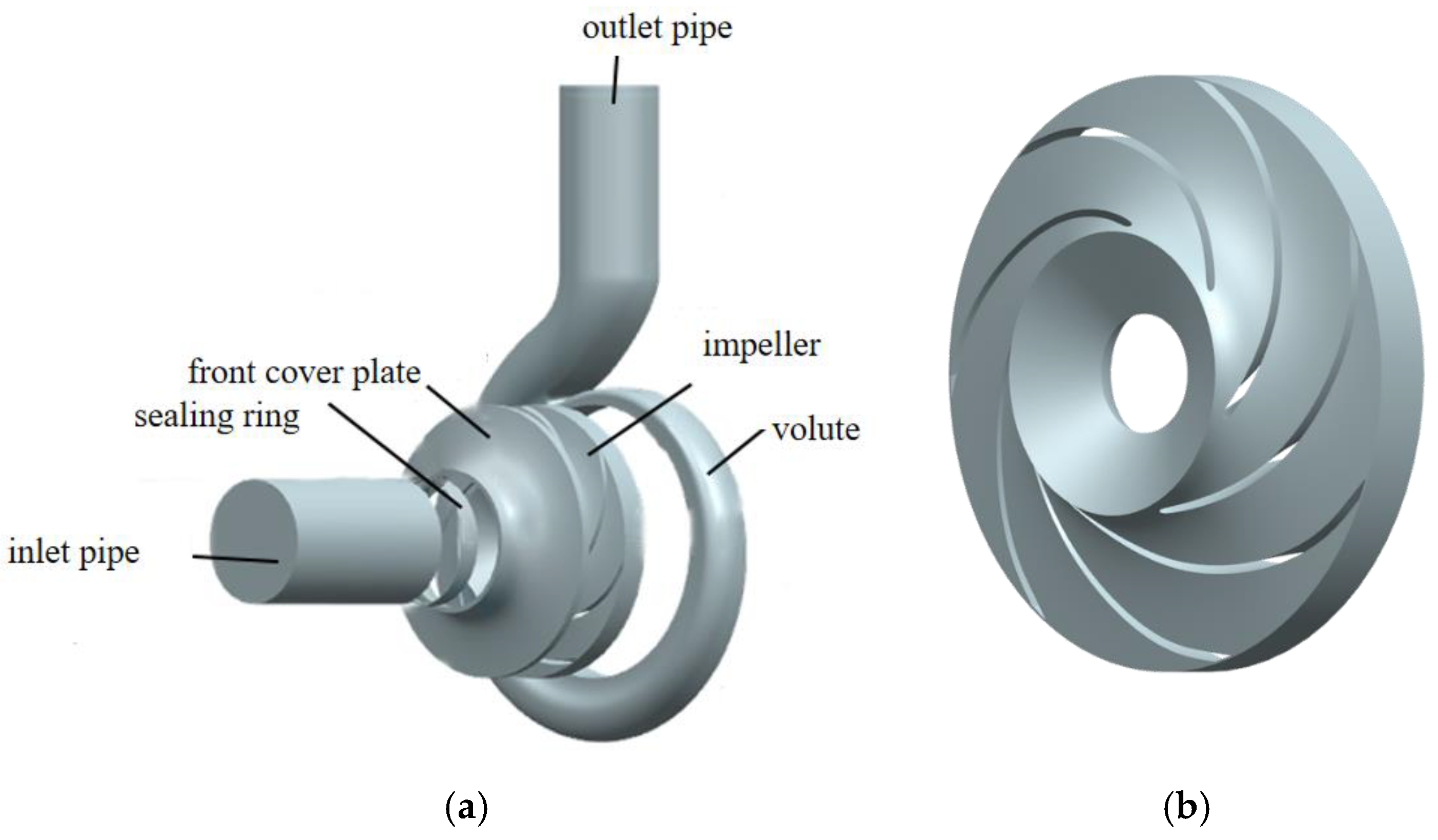
2.1. Structural Model

Taking the IS125-100-250 single-stage single-suction centrifugal pump produced by Zhejiang Yangzijiang Pump Co., Ltd. in Zhejiang Province, China as the research object, the calculation model includes six parts: inlet pipe, outlet pipe, impeller, volute, front cover plate and sealing ring. The pump length is 670 mm, the width is 400 mm, and the height is 505 mm. The inlet diameter of the pump is Din = 125 mm, the outlet diameter is Dout = 272 mm, the diameter of the impeller is 255 mm and the number of blades is 7. The performance parameters of the centrifugal pump are as follows: the flow rate is 175 m3/h, the head is 21.6 m, the power is 11.97 kW, the efficiency is 84.94%, and the speed is 1480 r/min. A three-dimensional drawing of the impeller wood model and the volute sketch of the centrifugal pump is created. Siemens NX 8.0 is used to model the six parts of the centrifugal pump, including the inlet pipe, the outlet pipe, the impeller, the volute, the front cover and the sealing ring. The main part of the modeling and the impeller model are shown in Figure 1.
Through the study of some special features, such as the sucker of the throat plate fish and the belly foot of the abalone, it is seen that the structure is similar to the groove structure. Based on this, V-shaped, circular and other groove structures can be designed and applied to the sealing ring. The sealing ring diagram of the bionic surface structure is shown in Figure 2, which has a V-groove and a circular groove, where r is the depth or radius of the groove, and l is the distance between the grooves. In order to find the bionic surface structure with the best sealing performance for the sealing ring, the depth of the groove and the distance between the grooves are set to constant values, taking r = 0.1 mm and l = 1 mm, respectively.

2.2. Numerical Calculation Model and Boundary Conditions

The turbulence models include k-ω turbulence model, RNG k-ε turbulence model, SST k-ω turbulence model and DCMFBM turbulence model [33,34,35] but, in general, the realizable k-ε turbulence model provides a good prediction for the boundary layer characteristics affected by the large pressure gradient, separated flow and recirculation gyre. When it comes to the calculation of separated flow and complex flow with secondary flow, it can predict the development of turbulence more accurately, capture the vortex structure at a smaller scale, and make the flow response in the shear layer more accurate.
The transformation model can be expressed as [36]:
k t + k u j x j = x j D k eff k x j + G k ε
ε t + ε u j x j = x j D ε eff ε x j + 2 C 1 ε S i j ε C 2 ε ε 2 k + v ε
where k represents turbulent kinetic energy, ε represents the turbulent dissipation rate, uj represents the velocity component of the fluid, xj represents Cartesian coordinates, t represents the computation time, v represents kinematic viscosity, Sij represents the average strain rate, Gk represents the turbulent kinetic energy generated by the average velocity gradient, Dkeff and eff are the effective diffusivity of k and ε [36], and C and C are set as constants.
The medium used in the simulation process is clear water, the water temperature is maintained at 25 °C, and standard atmospheric pressure is used as the external pressure, which is consistent with the actual environment under normal circumstances. The working condition is set to standard. The inlet of the centrifugal pump is set as the mass velocity inlet, the outlet is the static pressure outlet, and the wall condition is non-slip wall. The speed is set to 1480 r/min, and the flow rate is set to 87.5 m3/h, 122.5 m3/h, 157.5 m3/h, 175 m3/h, 192.5 m3/h, and 210 m3/h. Finite volume element analysis and the SIMPLEC algorithm are used.

2.3. Grid Division and Numerical Simulation Accuracy Verification

Mesh division is shown in Figure 3. ANSYS Fluent Meshing 2022 R1 is used to divide the structural network of the whole centrifugal pump and the seal ring gap of the centrifugal pump, and then grid independence analysis of the centrifugal pump is carried out. Grid independence analysis is shown in Table 1. By modifying the parameters in icem, the number of nodes is increased, the fluid domain grid is encrypted, and the number of grids is about 1.7 million. The type of mesh element is polyhedral mesh.
A centrifugal pump with a sealing ring clearance of 0.2 mm is selected. The head and efficiency of the centrifugal pump under different flow rates from 80 m3/h to 220 m3/h are obtained by numerical simulation. The pump characteristic curve is obtained by comparing with the theoretical data, as shown in Figure 4. From Figure 4, it can be seen that the head simulation value of the centrifugal pump begins to decrease when the initial flow rate is set to 80 m3/h, and decreases to the minimum when the maximum flow rate is set to 220 m3/h; in the range of 160–175 m3/h, efficiency reaches its maximum. When the flow rate is set to 175 m3/h, the theoretical volumetric efficiency is closest to the numerical simulation volumetric efficiency. The results show that, when the centrifugal pump is close to the range of flow rate at 175 m3/h, with the increase in flow rate, the difference between the actual value and the simulated value of head and efficiency decreases gradually. Therefore, a flow rate of 175 m3/h is the most suitable operating condition for centrifugal pumps. It is also seen that the simulated numerical variation curves of the head, and the efficiency and volumetric efficiency of the centrifugal pump are consistent with the theoretical numerical variation curves, and the deviations between them are also within a reasonable range. Therefore, the accuracy of the numerical simulation can also be guaranteed.

3. The Influence of Bionic Surface Structure on Sealing Performance

3.1. Effect of Bionic Surface Structure on Hydraulic Performance of Centrifugal Pump

The sealing ring models of different bionic surface structures are shown in Figure 5. Figure 5a is a smooth surface, and the surface is not treated; Figure 5b is a V-groove structure with a groove depth of 0.1 mm and a groove spacing of 1 mm. Figure 5c is a circular groove structure with a groove radius of 0.1 mm and a groove spacing of 1 mm.
The external characteristics and leakage characteristic curves of centrifugal pumps with different sealing rings are shown in Figure 6. On the sealing ring with a bionic structure, the overall trend is consistent with the sealing ring with a smooth surface. Under standard conditions, when the flow rate is 175 m3/h, the sealing ring of the circular groove structure has the best external characteristic performance and a certain increase in efficiency.
It can be seen from Figure 6 that, as the flow rate increases, the head of the centrifugal pump with three different sealing rings decreases. The efficiency of the centrifugal pump with the bionic surface structure sealing ring has improved to a certain extent, which indicates that the addition of the bionic surface structure will not interfere with the external characteristics of the whole centrifugal pump to a great extent but will also improve the external characteristics of the centrifugal pump to a certain extent. The change trend of the leakage of the sealing rings with different structures, along with the flow rate, is similar. As the flow rate increases, the leakage gradually increases and begins to decrease after reaching a certain value but, when it is close to the design flow rate, the change trend of the leakage is no longer significant. The change trend of this leakage may be related to the hydrodynamic characteristics of the centrifugal pump. With the increase in flow rate, more vortices are generated on the surface of the sealing ring, which makes the flow of the fluid more stable and makes the fluid firmly locked. Compared with the circular groove structure, the leakage of the V-groove structure is much larger, which may be due to the different fluid flow modes caused by its structure. Under standard working conditions, the circular groove structure can greatly reduce the leakage compared with the V-groove structure. Therefore, it can be seen that the sealing ring of the circular groove structure can reduce leakage without affecting the performance of the pump, while the leakage of the V-groove structure is larger. Compared with the circular groove structure, this is not suitable for the sealing ring of the centrifugal pump.

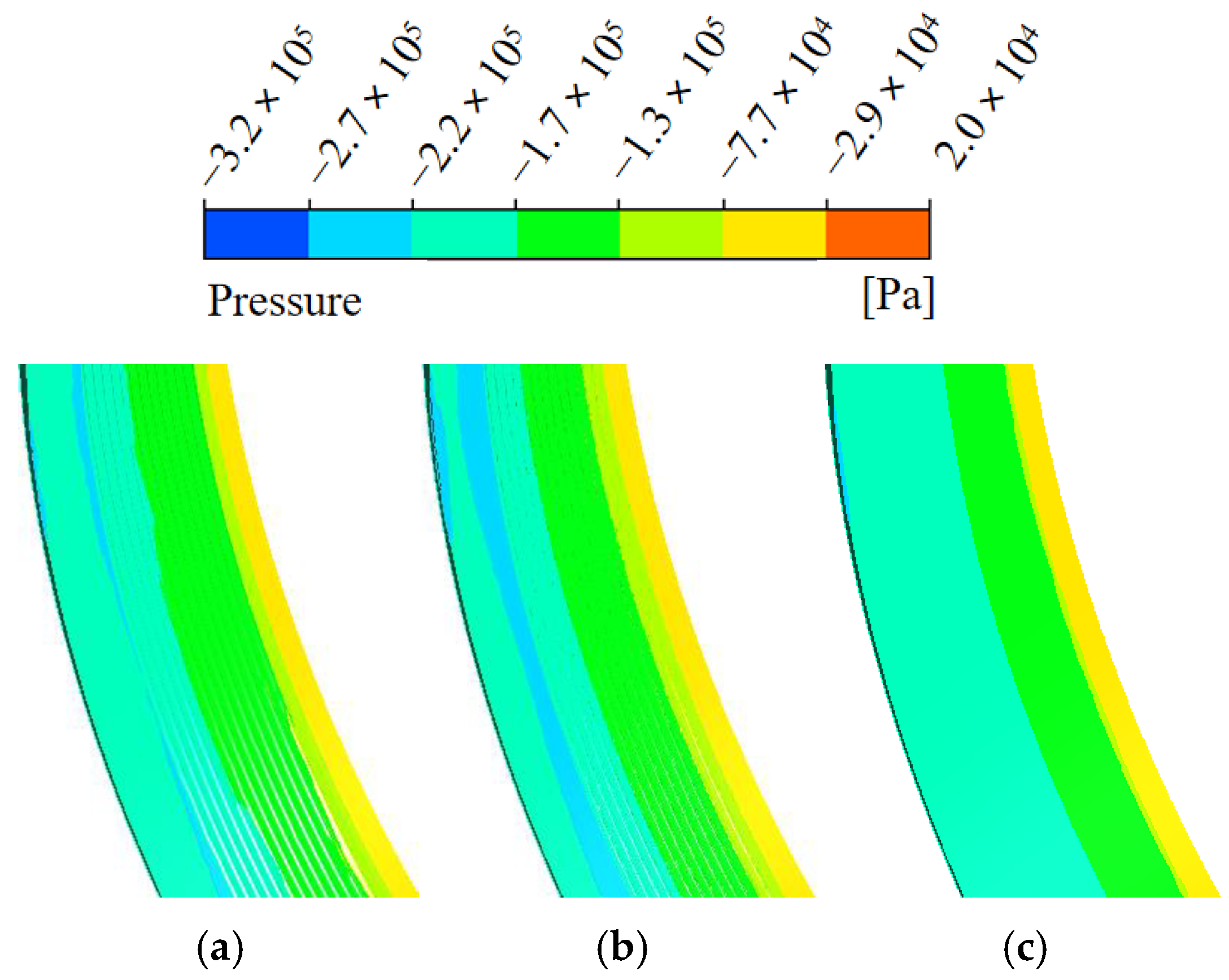
3.2. Internal Flow Field Analysis of Centrifugal Pump with Bionic Surface Structure Sealing Ring

The pressure distribution cloud diagram at the sealing ring for different surface structures is shown in Figure 7. It can be seen from Figure 7 that the outlet low pressure distribution and the inlet high pressure part of the circular groove structure are more than those of the V-groove structure and the smooth surface structure, which means that the circular groove structure has better sealing performance.
The velocity distribution cloud diagram at the sealing ring of different structures is shown in Figure 8. It can be seen from Figure 8 that the sealing performance is both strong and weak. The fluid velocity at the inlet and outlet of the sealing ring with a circular groove structure and V-groove structure is smaller than that of the inlet and outlet of the sealing ring with a smooth surface structure. Because the two structures have better sealing performance than the smooth surface structure, the fluid will not escape from the sealing ring, so that the fluid meets a certain obstacle at the sealing ring. Therefore, the flow rate of the smooth surface structure sealing ring at the inlet and outlet will not suffer more loss, resulting in a flow rate greater than that of the two bionic surface structures.
When the flow rate is 175 m3/h, the velocity vector diagrams under three different sealing ring structures are shown in Figure 9. It can be seen that the velocity vector at the contact between the front cover and the sealing ring has a certain relationship with the structure of the centrifugal pump sealing ring. It can be clearly seen that, under the condition that the effective cross-sectional area does not change, the sealing ring without a bionic structure produces strong velocity in the middle part of the sealing gap, and a velocity vortex is generated at the inlet end of the sealing gap. The sealing ring using the circular groove structure is compared with the sealing ring using the V-groove structure. The fluid velocity in the middle of the sealing gap of the sealing ring with circular groove structure has obviously reduced, and the sealing performance is enhanced. Therefore, the circular groove structure has better sealing performance.
When the flow rate is 175 m3/h, the vorticity diagram of the sealing ring with different structures is shown in Figure 10. It can be seen that the vorticity area at the sealing ring of the centrifugal pump is closely related to the structure of the sealing ring. If the sealing performance is poor, there will be a leakage between the inlet of the centrifugal pump and the sealing ring, resulting in a chaotic backflow and a very strong non-uniform eddy current. The sealing performance enhancement adds a certain bionic groove structure, and the gap of the sealing ring is unchanged. However, due to the existence of the groove, the gap is relatively reduced, the backflow generated inside the centrifugal pump will be relatively increased, and the number of shocks to the mainstream will begin to increase, so that the flow rate in the sealing gap will slow down. Comparing Figure 10a,b, it can be seen that the vortex formed in Figure 10b is more average. Compared with the circular groove structure, in the V-groove structure it can be seen that the vorticity of the sealing ring is unevenly distributed as a whole. This is due to the increase in hydraulic loss and volume loss caused by the leakage of the front cavity, which makes the flow transient of the internal flow field chaotic.

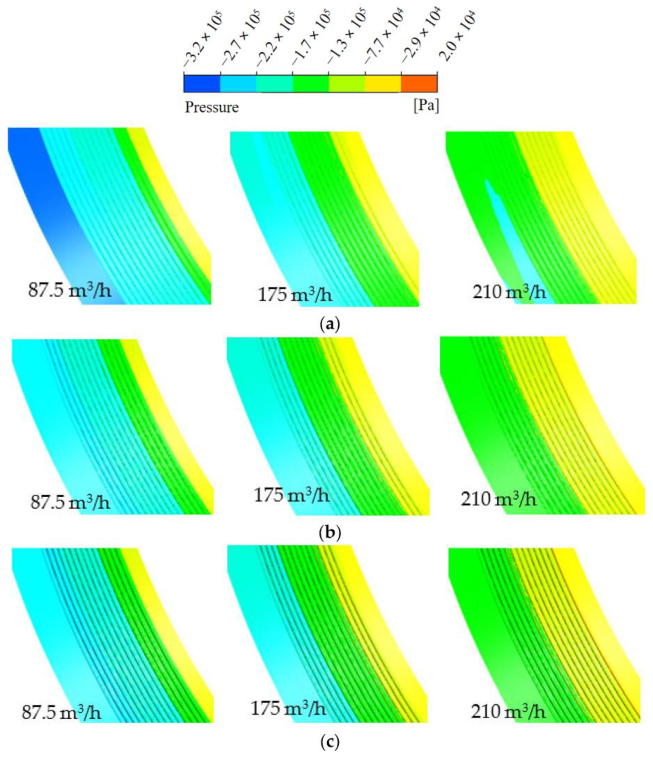
3.3. Analysis of Sealing Performance of Circular Groove Surface Structure

The sealing ring with circular groove structure with groove diameter of 0.4 mm and 0.6 mm is shown in Figure 11. All the figures are circular groove structures, and the groove spacing is 1 mm. The model with a groove diameter of 0.2 mm is shown in Figure 5c.
The pump characteristic curves of circular groove seal ring pumps with different diameters (d) are shown in Figure 12. It can be clearly seen from Figure 12a that, with the increase in flow rate, the head of the centrifugal pump with a circular groove structure will decrease rapidly. Among them, the curve trends of 0.4 mm and 0.6 mm in diameter are almost the same, but the head at each flow stage is weaker than that at 0.2 mm in diameter. It can be seen from Figure 12b that the flow–efficiency curves of the three circular groove structures with different diameters are almost the same. After the flow reaches a certain value, the efficiency of the circular groove structure with a diameter of 0.2 mm is greater than that of the two structures with diameters of 0.4 mm and 0.6 mm and, as the flow continues to increase, the downward trend in efficiency is also smaller than that of the other two structures. Figure 12c is the relationship between the leakage of the sealing ring of the circular groove surface structure with different diameters and the flow rate. It can be seen that the leakage of the sealing ring of the circular groove surface structure with three diameters first increases with the increase in the flow rate, then decreases and finally tends to be stable. Comparing the leakage of the sealing rings of the three structures, it can be seen that the leakage of the sealing ring of the circular groove surface structure with a diameter of 0.2 mm is the least among the three structures. Figure 12d shows the relationship between the volume efficiency of the sealing ring and the flow rate of the circular groove surface structure with different diameters. The volume efficiency trend of the three structures is the same, which increases with the increase in the flow rate. The volume efficiency of the circular groove surface structure seal ring with a diameter of 0.2 mm is slightly larger than that of the circular groove surface structure seal ring with a diameter of 0.4 mm and that of the circular groove surface structure seal ring with a diameter of 0.6 mm. The volume efficiency of the ring means that the circular groove surface structure seal ring with a diameter of 0.2 mm has the strongest sealing performance. Under different flow rates, the sealing performance of the circular groove structure is relatively optimal when the diameter is 0.2 mm.
According to the Stokes theorem, there is an equal relationship between the velocity of the fluid medium and the vortex intensity in the space of the region. The greater the water flow velocity, the greater the vortex intensity, which will continue to interfere with the original stable state of the fluid, resulting in an increase in the loss of fluid energy.
The pressure contours of circular groove seal rings with different diameters under different flow rates are shown in Figure 13. The horizontal comparison shows that, with the increase in flow rate, the high pressure part of the sealing ring at the water inlet gradually increases, and the whole becomes gradually close to the outlet section from the inlet section. The longitudinal comparison shows that the sealing rings with diameters of 0.4 mm and 0.6 mm are more in the high-pressure area of the middle section, while the sealing rings with diameters of 0.2 mm are less. This may be related to sealing performance and leakage. If the sealing performance is good, the fluid will not leak from the sealing ring, and the middle part will not have too many high-pressure areas.
The velocity contours of circular groove seal rings with different diameters at different flow rates are shown in Figure 14. The horizontal comparison shows that, with the increase in flow rate, the high-speed fluid part of the outlet end of the circular groove seal ring with different diameters gradually decreases. When the flow rate is close to 175 m3/h, the velocity distribution of each diameter sealing ring is basically similar, showing a stable distribution trend. Therefore, the sealing ring with circular groove structure will not affect the external characteristics of the centrifugal pump. From the longitudinal comparison, it can be clearly seen that the speed of the circular groove structure with a diameter of 0.2 mm at the outlet of the sealing ring is smaller than that of the circular groove structure with a diameter of 0.4 mm and 0.6 mm at the outlet of the sealing ring. The overall flow velocity of the middle part of the sealing ring with a circular groove structure with a diameter of 0.2 mm is smaller than that of the middle part of the sealing ring with a circular groove structure with a diameter of 0.4 mm and 0.6 mm. It is confirmed that the sealing performance of circular groove structures with diameters of 0.4 mm and 0.6 mm is relatively weak, which leads to fluid leakage in the middle part and increases the fluid velocity at the outlet. Therefore, when the diameter is 0.2 mm, the sealing performance of the circular groove structure is best.

4. Future Research

At present, we have studied the surface groove structure of the sealing ring and found that the structure can effectively improve its performance. In subsequent research, the focus can be on the arrangement of the circular groove structure and how it acts on the sealing performance. At the same time, the interval between different grooves cannot be ignored, and its influence on sealing performance can be systematically analyzed. In future research, we can study the roughness of the surface of the sealing ring, and the distribution, roughness and distribution density of the rough surface. In addition, the material of the sealing ring can be studied, and different material properties may have a greater impact on the performance of the sealing ring.

5. Conclusions

The Realizable k-ε turbulence model was used to numerically simulate different bionic groove surface structures and different groove diameters. The external characteristics, internal flow field distribution and leakage characteristics of the centrifugal pump were analyzed, and the most suitable bionic groove surface structure and the optimal groove diameter were determined. The main results are summarized as follows.
(1) Under standard working conditions, when the flow rate is 175 m3/h, the bionic surface structure has a certain promoting effect on the external characteristics of the centrifugal pump. Compared with that of the V-groove structure, the sealing ring of the circular groove structure has a certain increase in efficiency, which can effectively reduce the leakage. Among the three structures, the circular groove structure is more suitable as the sealing ring of a centrifugal pump.
(2) Through the analysis of the velocity, pressure and vorticity at the sealing ring, it is seen that, among the three different structures, the low pressure distribution at the outlet and the high pressure part at the inlet of the circular groove structure are the highest, the flow velocity at the inlet and outlet of the sealing ring is small, the formed vortex is more average, and the sealing performance is best.
(3) Through the analysis of the pump characteristic curve, pressure and speed of the circular groove sealing ring pump with different diameters, the circular groove surface structure sealing ring with a diameter of 0.2 mm shows the best performance. The head is the largest, the efficiency is the highest, the leakage is the least, the volume efficiency is the largest, the high pressure area is the least, the outlet flow rate is the smallest, and the sealing performance is best.

Author Contributions

Y.C.: methodology, data curation, formal analysis, writing—original draft; Z.X.: data curation, formal analysis, writing—review and editing; F.Y.: funding acquisition; M.Y. and C.M.: resources; Z.H. and Y.J.: supervision; J.M. and Y.G.: software. All authors have read and agreed to the published version of the manuscript.

Funding

This study was supported by the Zhejiang Provincial Natural Science Foundation of China (No. LY22E050015), and the Fundamental Research Funds for the Provincial Universities of Zhejiang (2023YW88).

Data Availability Statement

Data is contained within the article.

Conflicts of Interest

Author Zhengpu Xie was employed by the company Shanghai Bangpu Industrial Co., Ltd. Author Feixiang Yang was employed by the company Nanfang Pump Industry Co., Ltd. The remaining authors declare that the research was conducted in the absence of any commercial or financial relationships that could be construed as a potential conflict of interest.

References

  1. Aliuly, A.; Amanzholov, T.; Seitov, A.; Momysh, N.; Jaichibekov, N.; Kaltayev, A. Hydraulic design and CFD-Based parametric study for optimizing centrifugal pump impeller performance. Appl. Sci. 2024, 14, 10161. [Google Scholar] [CrossRef]
  2. Wang, C.; Shi, W.D.; Wang, X.K.; Jiang, X.P.; Yang, Y.; Li, W.; Zhou, L. Optimal design of multistage centrifugal pump based on the combined energy loss model and computational fluid dynamics. Appl. Energy 2017, 187, 10–26. [Google Scholar] [CrossRef]
  3. Zhang, Y.; Jiang, W.; Feng, W.; Jia, Q.F.; Wang, Y.C.; Chen, D.Y. Investigation of hydraulic losses in different clocking positions of pump-turbine in pump mode. J. Energy Storage 2024, 81, 110459. [Google Scholar] [CrossRef]
  4. Gao, Y.; Li, W.; Qi, H.D.; Ji, L.L.; Chen, Y.F. Optimized design of a multistage centrifugal pump based on volumetric loss reduction by auxiliary blades. Water 2023, 15, 2350. [Google Scholar] [CrossRef]
  5. Yan, J.R.; Zuo, Z.T.; Guo, W.B.; Hou, H.C.; Zhou, X.; Chen, H.S. Influences of wear-ring clearance leakage on performance of a small-scale pump-turbine. Proc. Inst. Mech. Eng. Part A J. Power Energy 2020, 234, 454–469. [Google Scholar] [CrossRef]
  6. Zhou, W.J.; Ma, J.; Ma, Z.L.; Yu, W.B.; Su, H.H.; Gao, B. Fluid–structure interaction on the rotor-dynamic characteristics of a low-specific-speed centrifugal pump considering multi-scale fluid excitation effects. Phys. Fluids 2024, 36, 117257. [Google Scholar] [CrossRef]
  7. Zhou, W.J.; Qiu, N.; Wang, L.Q.; Gao, B.; Liu, D. Dynamic analysis of a planar multi-stage centrifugal pump rotor system based on a novel coupled model. J. Sound Vib. 2018, 434, 237–260. [Google Scholar] [CrossRef]
  8. Van Der Walt, J.P.; Kruger, J.-H.; Du Toit, C.G. Implementation of a reduced order model for rotating seal annular leakage flow inside a centrifugal pump. Geoenergy Sci. Eng. 2024, 233, 212470. [Google Scholar] [CrossRef]
  9. Jia, X.Q.; Yu, Y.F.; Li, B.; Wang, F.C.; Zhu, Z.C. Effects of incident angle of sealing ring clearance on internal flow and cavitation of centrifugal pump. Proc. Inst. Mech. Eng. Part E J. Process Mech. Eng. 2023, 238, 2867–2882. [Google Scholar] [CrossRef]
  10. Qiu, Q.F.; Gu, Y.Q.; Ma, L.B.; Hu, C.X.; Ding, H.X.; Wu, D.H.; Mou, J.G.; Wu, Z.X. Study of non-constant local cavitation suppression in micro-wedge structure. Phys. Fluids 2024, 36, 015150. [Google Scholar] [CrossRef]
  11. Hu, Y.; Zhang, J.; Chen, L.M. Design and seal performance analysis of bionic sealing ring for dynamic seal. Mechanics 2020, 26, 338–345. [Google Scholar] [CrossRef]
  12. Chen, H.L.; Chen, Y.J.; Han, T.; Fu, Y.X.; Cheng, Q.; Wei, Z.P.; Zhao, B.J. Effect of surface roughness on the performance of a shallow spiral groove liquid mechanical seal. Processes 2022, 10, 651. [Google Scholar] [CrossRef]
  13. Chen, H.Q.; Yan, R.Q.; Hong, X.Z.; Bao, X.; Ding, X.X. Micro-groove optimisation of high-speed inner ring micro-grooved pumping seal for new energy electric vehicles. Processes 2024, 12, 1281. [Google Scholar] [CrossRef]
  14. Sandoval, J.A.; Jadhav, S.; Quan, H.C.; Deheyn, D.D.; Tolley, M.T. Reversible adhesion to rough surfaces both in and out of water, inspired by the clingfish suction disc. Bioinspiration Biomim. 2019, 14, 066016. [Google Scholar] [CrossRef]
  15. Tramacere, F.; Appel, E.; Mazzolai, B.; Gorb, S.N. Hairy suckers: The surface microstructure and its possible functional significance in the Octopus vulgaris sucker. Beilstein J. Nanotechnol. 2014, 5, 561–565. [Google Scholar] [CrossRef] [PubMed]
  16. Tramacere, F.; Pugno, N.M.; Kuba, M.J.; Mazzolai, B. Unveiling the morphology of the acetabulum in octopus suckers and its role in attachment. Interface Focus 2015, 5, 20140050. [Google Scholar] [CrossRef] [PubMed]
  17. Kimbara, R.; Nakamura, M.; Oguchi, K.; Kohtsuka, H.; Miura, T. Pattern of sucker development in cuttlefishes. Front. Zool. 2020, 17, 24. [Google Scholar] [CrossRef]
  18. Tramacere, F.; Beccai, L.; Kuba, M.; Gozzi, A.; Bifone, A.; Mazzolai, B. The morphology and adhesion mechanism of octopus vulgaris suckers. PLoS ONE 2013, 8, e65074. [Google Scholar] [CrossRef] [PubMed]
  19. Ditsche, P.; Summers, A. Learning from northern clingfish (Gobiesox maeandricus): Bioinspired suction cups attach to rough surfaces. Philos. Trans. R. Soc. B Biol. Sci. 2019, 374, 20190204. [Google Scholar] [CrossRef] [PubMed]
  20. Wang, J.H.; Wang, S.K.; Zheng, L.; Ren, L.Q. Adhesion behavior in fish: From structures to applications. Biomimetics 2023, 8, 534. [Google Scholar] [CrossRef]
  21. Li, J.; Zhang, Y.; Liu, S.; Liu, J.L. Insights into adhesion of abalone: A mechanical approach. J. Mech. Behav. Biomed. Mater. 2018, 77, 331–336. [Google Scholar] [CrossRef]
  22. Xi, P.; Cong, Q.; Xu, J.; Sun, L. Surface movement mechanism of abalone and underwater adsorbability of its abdominal foot. Bioinspired Biomim. Nanobiomaterials 2019, 8, 254–262. [Google Scholar] [CrossRef]
  23. Lin, A.Y.M.; Brunner, R.; Chen, P.Y.; Talke, F.E.; Meyers, M.A. Underwater adhesion of abalone: The role of van der Waals and capillary forces. Acta Mater. 2009, 57, 4178–4185. [Google Scholar] [CrossRef]
  24. Xi, P.; Ye, S.B.; Cong, Q. Abalone adhesion: The role of various adhesion forces and their proportion to total adhesion force. PLoS ONE 2023, 18, e0286567. [Google Scholar] [CrossRef]
  25. Wang, J.; Yu, P.F.; Li, R.; Liu, Y.J.; Wang, T.G.; Liu, C. Effect of structural parameters of rectangular grooves on lubrication performance of water-lubricated bearings. Ship Eng. 2024, 46, 90–98. [Google Scholar] [CrossRef]
  26. He, T.; Zhang, Q.Q.; Yan, Y.; Dong, J.T.; Zhou, P. Numerical simulation of a new designed mechanical seals with spiral groove structures. Lubricants 2023, 11, 70. [Google Scholar] [CrossRef]
  27. Tian, L.M.; Tian, X.M.; Wang, Y.C.; Hu, G.L.; Ren, L.Q. Anti-wear properties of the molluscan shell Scapharca subcrenata: Influence of surface morphology, structure and organic material on the elementary wear process. Mater. Sci. Eng. C 2014, 42, 7–14. [Google Scholar] [CrossRef] [PubMed]
  28. Hirvonen, J.P.; Lappalainen, R.; Koskinen, J.; Likonen, J.; Pekkarinen, M. Wear and friction of unio crassus shell in dry sliding contact with steel. Mrs Online Proc. Libr. 1993, 330, 133–137. [Google Scholar] [CrossRef]
  29. Gu, Y.Q.; Ma, L.B.; Yan, M.H.; He, C.D.; Zhang, J.J.; Mou, J.G.; Wu, D.H.; Ren, Y. Strategies for improving friction behavior based on carbon nanotube additive materials. Tribol. Int. 2022, 176, 107875. [Google Scholar] [CrossRef]
  30. He, W.L.; Ahmat, M.; Zhou, H.F.; Li, Z.H.; Qiu, W.; Li, D.Z. Influence of diamond-like carbon coatings and micro-texturing on friction and wear of seal interfaces: Experiment and simulation study. Proc. Inst. Mech. Eng. Part E J. Process Mech. Eng. 2024, 23, 09544089241226632. [Google Scholar] [CrossRef]
  31. Zhang, N.; Liu, Y.C.; Li, Z.T.; Zhan, X.H. Sealing performance and optimization design of squamous textured mechanical seal. Tribol. Int. 2024, 193, 109425. [Google Scholar] [CrossRef]
  32. Ning, H.W.; Qian, S.Z.; Zhou, T. Applications of level set method in computational fluid dynamics: A review. Int. J. Hydromechatronics 2023, 6, 1–33. [Google Scholar] [CrossRef]
  33. Gu, Y.Q.; Qiu, Q.F.; Ren, Y.; Ma, L.B.; Ding, H.X.; Hu, C.X.; Wu, D.H.; Mou, J.G. Cavitation flow of hydrofoil surface and turbulence model applicability analysis. Int. J. Mech. Sci. 2024, 277, 109515. [Google Scholar] [CrossRef]
  34. Gu, Y.Q.; Yin, Z.F.; Yu, S.W.; He, C.D.; Wang, W.T.; Zhang, J.J.; Wu, D.H.; Mou, J.G.; Ren, Y. Suppression of unsteady partial cavitation by a bionic jet. Int. J. Multiph. Flow 2023, 164, 104466. [Google Scholar] [CrossRef]
  35. Qu, K.; Xu, Y.Y.; Huang, J.X.; Wen, B.H. Numerical simulation of hydrodynamic characteristics of submerged floating tunnels under the action of focused waves. J. Chang. Univ. Sci. Technol. 2023, 20, 127–141. [Google Scholar] [CrossRef]
  36. Shaheed, R.; Mohammadian, A.; Kheirkhah Gildeh, H. A comparison of standard k-ε and realizable k-ε turbulence models in curved and confluent channels. Environ. Fluid Mech. 2019, 19, 543–568. [Google Scholar] [CrossRef]
Figure 1. (a) Modeling of main parts of centrifugal pump. (b) Impeller model.
Lubricants 13 00026 g001
Figure 2. Hydraulic model of bionic surface structure sealing ring. (a) V-groove profile diagram. (b) Three-dimensional model of V-groove. (c) Circular groove profile diagram. (d) Circular groove profile diagram.
Lubricants 13 00026 g002
Figure 3. Mesh subdivision. (a) Centrifugal pump overall grid. (b) Sealing ring gap grid.
Lubricants 13 00026 g003
Figure 4. Pump characteristic curve. (a) Flow–head comparison curve. (b) Flow–efficiency comparison curve. (c) Flow–volume efficiency comparison curve.
Lubricants 13 00026 g004
Figure 5. Sealing ring models with different bionic surface structures. (a) Smooth surface (b) V-groove structure. (c) Circular groove structure.
Lubricants 13 00026 g005
Figure 6. Pump characteristic curves of sealing rings with different surface structures. (a) Flow–head curve. (b) Flow–efficiency curve. (c) Flow–leakage curve.
Lubricants 13 00026 g006
Figure 7. Pressure distribution cloud chart of different sealing ring structures. (a) V−groove structure sealing ring. (b) Circular groove structure sealing ring. (c) Smooth surface sealing ring.
Lubricants 13 00026 g007
Figure 8. Velocity distribution nephogram of sealing rings of different structures. (a) V−groove structure sealing ring. (b) Circular groove structure sealing ring. (c) Smooth surface sealing ring.
Lubricants 13 00026 g008
Figure 9. Velocity vector diagram of seal rings with different structures on X = 0 datum plane. (a) V−groove structure sealing ring. (b) Circular groove structure sealing ring. (c) Smooth surface structure sealing ring.
Lubricants 13 00026 g009
Figure 10. Vortex diagram of sealing rings with different structures at 175 m3/h. (a) V−groove structure sealing ring. (b) Circular groove structure sealing ring. (c) Smooth surface sealing ring.
Lubricants 13 00026 g010
Figure 11. Circular groove structure with diameters of 0.4 mm and 0.6 mm. (a) d = 0.4 mm. (b) d = 0.6 mm.
Lubricants 13 00026 g011
Figure 12. Pump characteristic curves of circular groove seal ring pumps with different diameters. (a) Flow–head curve. (b) Flow–efficiency curve. (c) Flow–leakage curve. (d) Flow–volume efficiency curve.
Lubricants 13 00026 g012
Figure 13. Under the condition of flow rate of 87.5 m3/h, 175 m3/h and 210 m3/h, the pressure cloud diagram of circular groove sealing ring with different diameters. (a) d = 0.2 mm. (b) d = 0.4 mm. (c) d = 0.6 mm.
Lubricants 13 00026 g013
Figure 14. Under flow rate conditions of 87.5 m3/h, 175 m3/h and 210 m3/h, the velocity cloud diagram of circular groove seal ring with different diameters. (a) d = 0.2 mm. (b) d = 0.4 mm. (c) d = 0.6 mm.
Lubricants 13 00026 g014
Table 1. Grid independence analysis.
Grid NumbersHead (m)Efficiency (%)Flow Rate (m3/h)Motor Power (kW)
Whole grid 1765,43422.8886.1517511.97
Whole grid 21,213,47923.0987.2717511.97
Whole grid 31,440,99223.2087.3317511.97
Whole grid 41,695,52323.3087.4017511.97
Whole grid 52,245,70923.3187.4117511.97
Whole grid 62,634,59023.2887.3917511.97
Disclaimer/Publisher’s Note: The statements, opinions and data contained in all publications are solely those of the individual author(s) and contributor(s) and not of MDPI and/or the editor(s). MDPI and/or the editor(s) disclaim responsibility for any injury to people or property resulting from any ideas, methods, instructions or products referred to in the content.

