1. Introduction
The cracks in cages frequently appear, resulting from microcracks in the manufacturing process and also complex forces and frequent impacts between the parts in the bearing during operation. When the actual load exceeds its strength limit, the cage can easily crack [
1]. Cracks in a cage can change its structural stiffness and pocket clearance, directly affecting the dynamic characteristics of the bearing, and thus can even lead to the reduction in strength or failure of the bearing. Therefore, the dynamic analysis of cylindrical roller bearings under crack conditions is of great significance to theoretical research and engineering applications.
At present, the research in the field of bearing dynamics is very comprehensive. Gupta et al. [
2,
3,
4,
5] constructed a dynamic model of bearing parts with six degrees of freedom (DOF) and carried out dynamic simulation and motion analysis. Neglia et al. [
6] established a bearing cage model incorporating three DOF and identified the key parameters that influence the cage’s motion and lifespan. Houpert et al. [
7,
8] developed a three-DOF cage model that accounts for the radial and orbital centrifugal forces on the outer race and cage, respectively, and analyzed the trajectory of the cage’s center of mass. Meeks et al. [
9,
10] simplified Gupta’s model to establish a dynamic model for bearings, reducing the interaction forces between the rolling elements and the cage using damped springs, suitable for solid-lubricated bearings under axial load. Ghaisas et al. [
11] constructed a simulation model with six DOF for the dynamics of a cylindrical roller bearing to investigate the effects of variations in the inner race speed, misalignment, cage asymmetry, and the change in size of one roller, examining the cage instability in relation to the clearances between the roller and race and the roller and cage pocket under light-load and high-speed conditions. Sakaguchi and Kaoru [
12] constructed a dynamic model of the cage of a cylindrical roller bearing and analyzed the centroid motion and stress of the cage. Sakaguchi et al. [
13] developed a dynamic model for tapered roller bearings, focusing on the impact of varying rotational speeds and axial loads on the motion of the cage’s center of mass and the whirl radius. Although the above research has established the bearing dynamics model, considerations of the dynamics of the cage fault and its flexibility are lacking.
In terms of cage failure, McFadden et al. [
14] developed a vibration model for rolling element bearings with a single point defect on the inner race under a constant radial load. Choe et al. [
15] analyzed the dynamic behavior of a rolling element bearing’s cage through experiments, focusing on the cage’s whirling amplitude, ball bearing torque, and cage wear, as well as the influence of the cage’s mass imbalance on these parameters. Shi et al. [
16] introduced a bearing model with a cracked cage, taking into account the interactions between the roller and the cracked cage, and investigated the impact of cage cracks on the forces and vibrations of the cage. Yu et al. [
17] proposed bearing models with cage cracks at different positions, considering the friction force and roller motion. Chen et al. [
18] focused on a fractured cage to investigate the dynamic mechanisms of a cylindrical roller bearing with cage failure. Tian et al. [
19] established a nonlinear rolling bearing model, factoring in cage fracture, to study its nonlinear vibration characteristics and analyze the nonlinear behavior resulting from cage fracture. Wang et al. [
20] developed a five-DOF bearing force model that accounts for misalignment and cage fracture, constructing a dynamic model of the deep groove ball bearing–rotor system to investigate the vibrational characteristics of cage fracture faults. Li et al. [
21] considered the complex interactions among the elements of the rolling bearing and established a dynamic model for bearings with a fractured cage, revealing the influence patterns on the bearing’s dynamic characteristics. Tanaka [
22] proposed a stochastic damage accumulation model for high-cycle fatigue crack initiation, in which fatigue damage was assumed to accumulate as dislocations under repeated stress, with slip band cracks initiated when the strain energy from local dislocation pile-up exceeded a critical value. Although the research of the above scholars focuses on the fatigue fracturing and cracking of the cage, the influence of the crack depth, angle, and position of the cage on the dynamic characteristics and cage life of the bearing has not been discussed.
In terms of the dynamic analysis of bearings, Sadeghi’s team [
23,
24,
25,
26] firstly constructed a contact fatigue spalling model of roller bearings based on the principle of damage mechanics to analyze the influence of material residual stress, random defects, and plastic deformation on the whole life cycle of contact fatigue spalling initiation and propagation to failure. Kabus et al. [
27] developed a comprehensive model for a cylindrical roller bearing, analyzing the bearing load distribution and fatigue life. Warda et al. [
28] proposed a method for predicting the fatigue life of radial cylindrical roller bearings, taking into account the radial clearance, roller profiles, combined loads, and misalignment and their effects on fatigue life. Although the above studies have established multiple bearing fatigue life models, there are still few studies on the prediction of crack propagation.
However, the influence mechanism of cage cracks on bearing dynamics and reliability remains elusive, necessitating a comprehensive investigation. A dynamic model of a cylindrical roller bearing with cage cracks is established, and the influence of crack depth, angle, and position on the dynamic characteristics and cage life of the bearing are investigated. This study will contribute to understanding the propagation behavior of cracks.
2. Rigid and Flexible Coupling Dynamic Model of a Cylindrical Roller Bearing Considering a Flexible Cage with Cracks
Based on the rigid body dynamics model of the bearing, the finite element model of the flexible cage with cracks is introduced into the dynamic model, and the rigid–flexible coupling model of the cylindrical roller bearing with cracks is established. In
Figure 1, the inner ring, outer ring, and roller are all rigid parts, and the cage is considered as a flexible part.
Regarding the cylindrical roller bearing dynamics model, the following assumptions are adopted:
- (1)
The center of mass of each part in the bearing coincides with its geometric center;
- (2)
The cage is considered flexible, while the other parts are rigid;
- (3)
We refrain from considering the impact of fluctuations in internal bearing temperature;
- (4)
The inner ring and cage of the bearing have three DOF in the radial and translational directions and rotate around its axis;
- (5)
The roller of the bearing has four DOFs including revolution around and its axis, as well as transitional motion in a radial plane;
- (6)
The outer ring of the bearing has two DOFs, adopted as the equivalent stiffness and damping force.
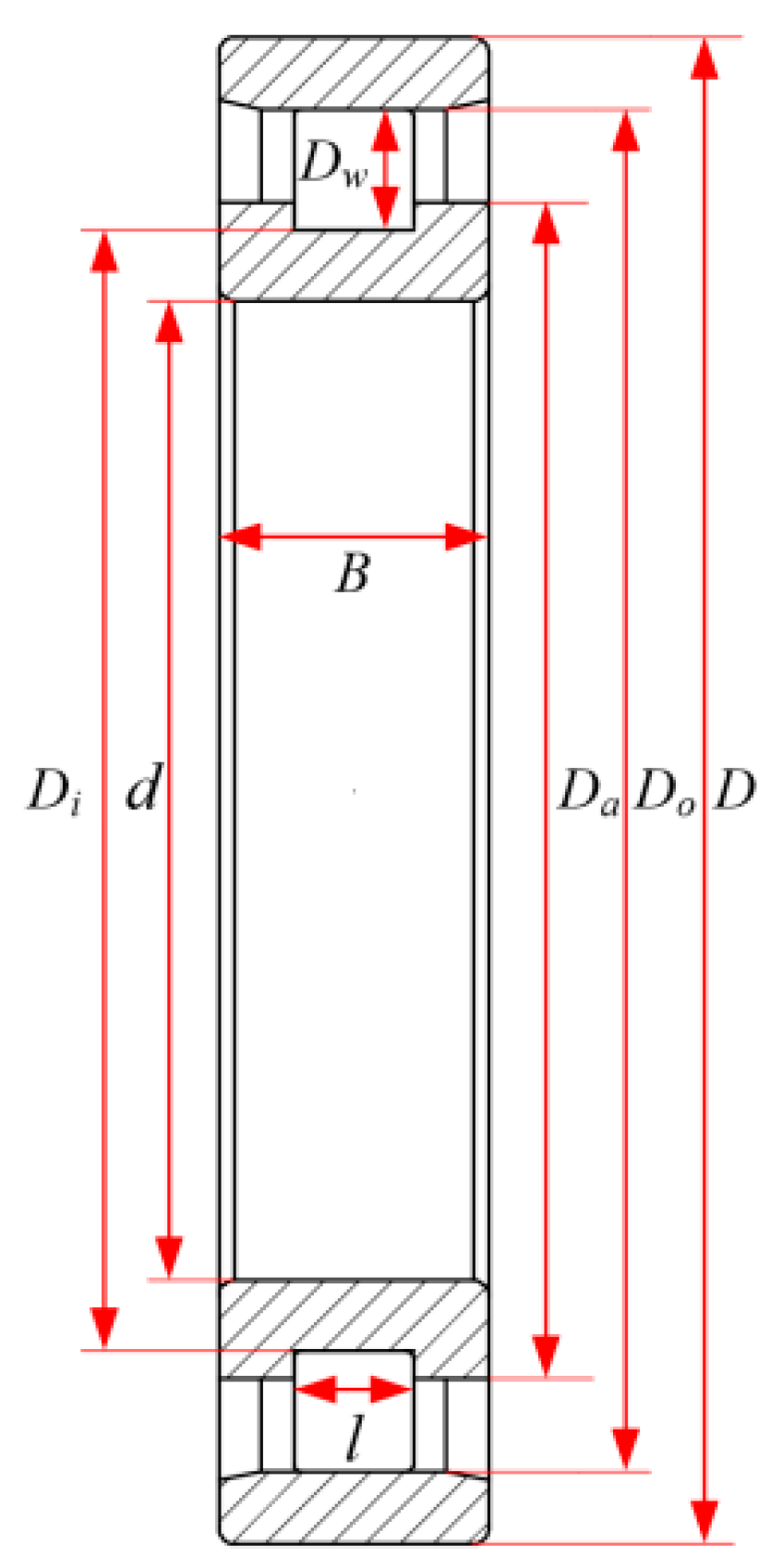
The N1013 cylindrical roller bearing is selected. The structure of the cylindrical roller bearing is illustrated in
Figure 2, and the structural parameters are listed in
Table 1.
The material of the ring and roller is GCr15, and the material of cage is brass. The material parameters are shown in
Table 2.
2.1. Differential Equation of Bearing Dynamics
The radial load on the cylindrical roller bearing at some moment during operation is shown in
Figure 3. Rollers mainly withstand the internal and external raceway and cage forces and lubricant resistance.
and are the contact force between the inner and outer raceways and rollers, respectively. , and are the drag forces of the inner and outer raceways and cage on the th roller, respectively. is the centrifugal force of the roller. is the normal force of cage to roller. and are the turbulent flow resistance force and moment of roller revolution and rotation, respectively. is the rotational speed of the roller.
According to the above force analysis, the differential equation of the roller’s radial direction motion is
where
is the mass of roller.
and
are the displacements of the rollers.
is the revolution angle of the roller relative to the bearing inertial coordinate system.
The differential equation of motion of the roller rotation and revolution direction is
where
,
,
and
are the diameters of the roller, the inner and outer raceways, and the pitch circle, respectively.
and
are the moment of inertia of the roller rotation and revolution, respectively.
and
are the rotation angles of the roller rotation and revolution, respectively.
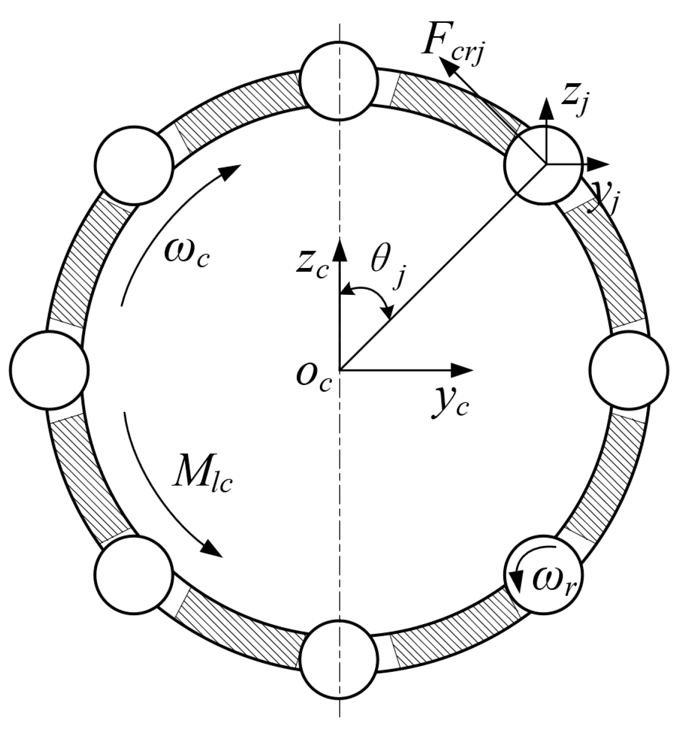
The cage is mainly subjected to the force of the roller and the lubricant, as shown in
Figure 4. In this figure,
is the force of the roller on the cage.
is the resistance of the lubricant to the cage.
is the rotational speed of the cage.
The cage motion’s differential equation is
where
and
are the rotational inertia around the X axis and the mass of the cage, respectively.
and
are the displacements of the cage.
2.2. Internal Interaction in Cylindrical Roller Bearing
In order to solve the differential equation of bearing dynamics, the interaction force of the internal parts of the bearing should be analyzed to determine the initial value of the differential equation. The analysis process is as follows.
2.2.1. Forces Between Rollers and Raceways
At a certain moment during operation, the displacements of the inner ring and the
th roller in the bearing inertial coordinate system are
and
, respectively. The relative position of the roller and the inner ring is shown in
Figure 5.
From
Figure 5, the center vector
of the inner ring and the roller is
where
is the rotation transformation matrix from the inner ring coordinate system to the bearing coordinate system.
is the distance between the roller center and the inner ring center.
is the azimuth angle of the
th roller relative to the bearing inner ring coordinate system.
The contact force between the inner ring raceway and the roller is in the direction of the vector
. Under the force, the corresponding contact deformation is
where
is the radius of the inner raceway.
is the radial clearance of the bearing.
According to Hertz’s theory, the normal contact force between the
th roller and the inner raceway is calculated as
where
is the contact stiffness between the roller and the inner raceway, which can be calculated with the method in [
29]. Similarly, the normal contact force between the roller and the outer raceway can be calculated as
The drag force on the surface of the roller and the inner raceway can be obtained by the product of the normal contact force and the drag coefficient between the roller and the raceway, namely
Similarly, the drag force between the roller and the outer raceway can be expressed as
where
is the friction coefficient. The friction coefficient is determined by the relative sliding speed
between the two contact parts. The calculation formula is as follows:
where
is the static friction transition speed,
is the dynamic friction transition speed,
is the maximum static friction coefficient, and
is the dynamic friction coefficient.
2.2.2. Force Between the Roller and Cage
At a certain moment during operation, the displacements of the cage and the
th roller are
and
, respectively. The specific location relationship is shown in
Figure 6.
It can be deduced from this figure that the vector from the center of the pocket to the center of the roller is expressed as
where
is the radius of the roller in the pocket.
is the azimuth angle of the
th pocket center relative to the cage centroid.
The contact force between the roller and the pocket is in the direction of the vector
. Under the force, the corresponding contact deformation is
where
is the pocket clearance between the cage and the roller.
The contact between the pocket and the roller can be regarded as Hertz contact, and the contact stiffness can be obtained by referring to [
29]. The contact force between the pocket and the roller is
The drag force of the cage on the roller can be expressed as
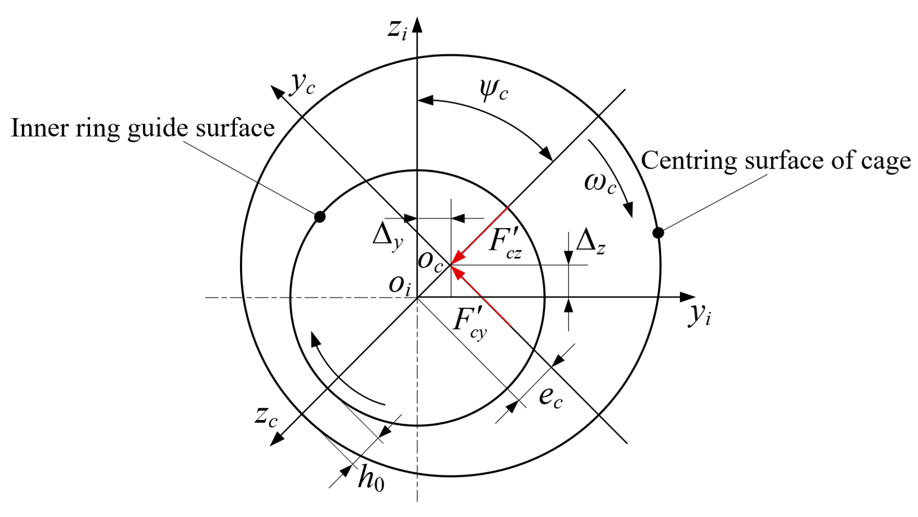
2.2.3. Force Between the Cage and Guide Ring
The guiding force of the inner ring to the cage is due to the hydrodynamic effect of the lubricant. The guide surface of the inner ring and the centering surface of the cage are regarded as journal bearings with an infinite short and thick oil film [
30]. The force analysis of the cage and the guide ring is shown in
Figure 7.
The two orthogonal components
and
acting on the retainer can be expressed as
where
is the dynamic viscosity of lubricating oil under normal pressure.
is the width of the cage centering surface.
is the guiding clearance of the cage.
is the relative eccentricity of the cage center.
is the drag speed of the lubricant.
2.2.4. Force of Oil-Gas Acting on the Rollers and Cage
The lubricant resistance of the roller revolution is
where
is the resistance coefficient.
is the density of the lubrication oil.
is the linear velocity of roller revolution. A is the roller section area.
The blocking torque of the cage cylindrical surface is
where
is the shear force of the lubricant.
is the surface area of the cage guide surface.
is the guide surface diameter of the cage.
The rotational resistance moment of the roller is
where
is the surface area of the roller cylindrical surface.
2.3. Flexible Cage with Cracks
2.3.1. Crack Characterization of the Cage
The selection of crack initiation points is based on the most common stress concentration areas in the cage structure. In actual operation, the side beam and cross beam of the cage usually bear a large force and are the most prone to cracking. Therefore, side beams and cross beams are selected as the key areas for cracking.
The characterization of cage cracks includes the crack depth, crack angle, and crack position.
Figure 8 shows the crack characterization in cage pockets, in which the crack depth l is the crack initiation distance, the crack angle
is the angle between the crack and the cage axis, and the crack position is on the pocket beam and the side beam.
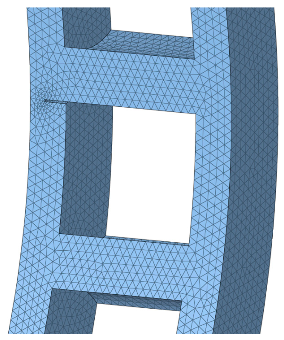
The flexibility of the cage was modeled utilized SOLID185 elements, with the mesh divided using standard tetrahedral elements. The finite element mesh division results are shown in
Figure 9.
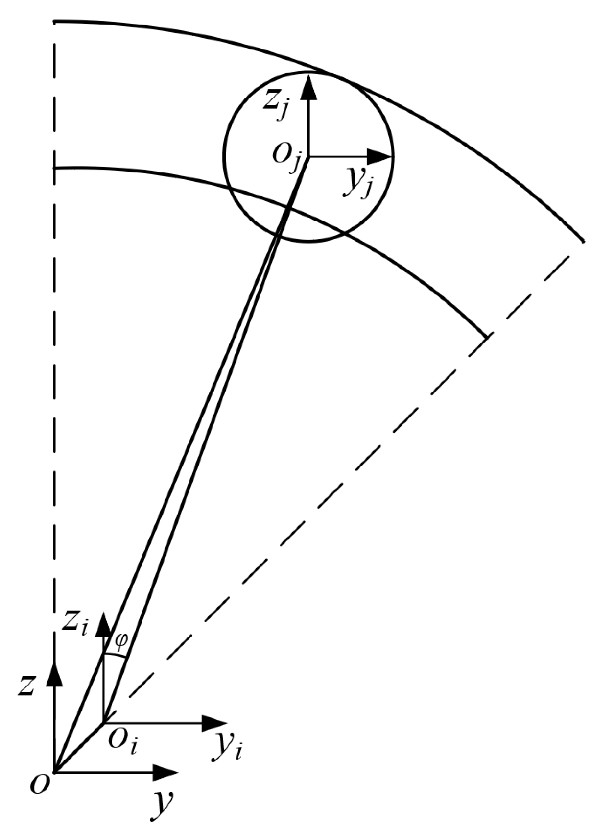
2.3.2. Position of Flexible Cage
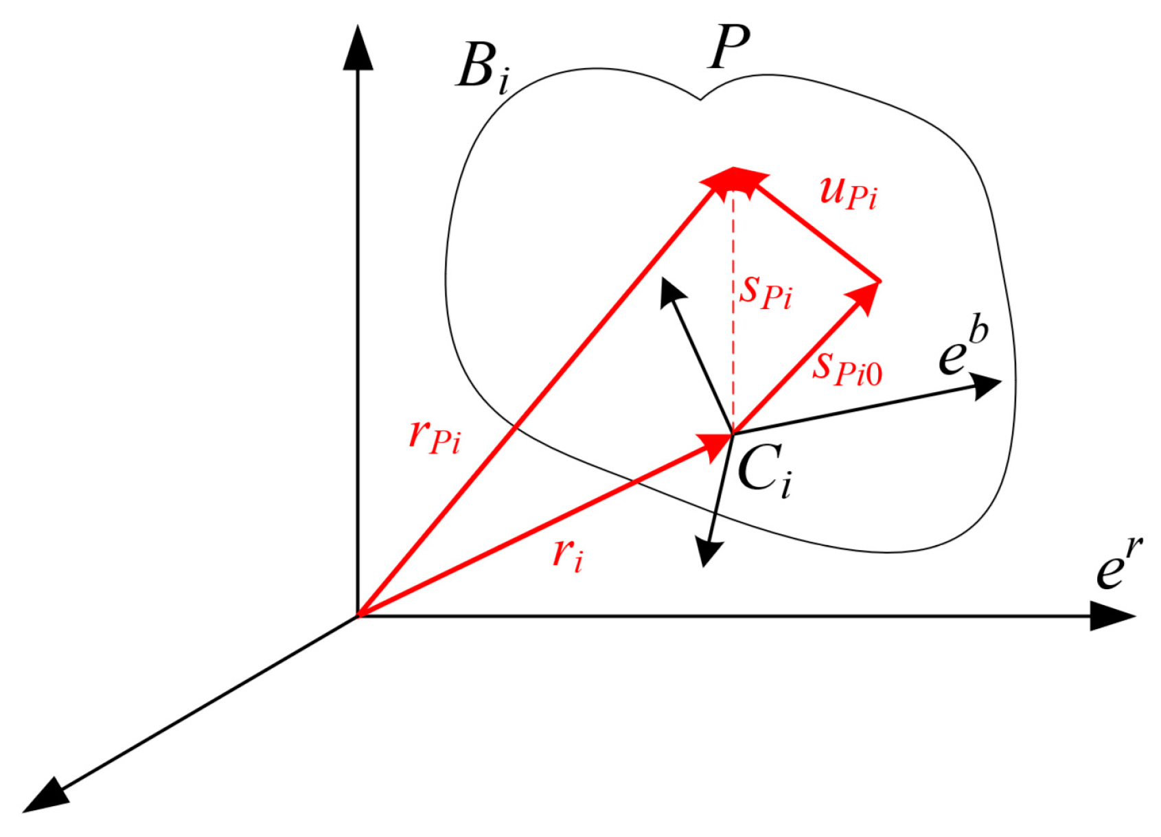
The position coordinate system of the node
in the flexible body is shown in
Figure 10, which covers the fixed inertial coordinate system (
) and the dynamic coordinate system (
). The position of the inertial coordinate system is fixed, while the dynamic coordinate system changes with the displacement and rotation of the flexible body, and the position and direction of the dynamic coordinate system relative to the inertial coordinate system are defined as the reference coordinates [
31].
2.3.3. Velocity and Acceleration at One Point of the Flexible Cage
In order to model the planar motion of the small deformation of a flexible body, it is necessary to split the complex process into several basic motion types. For example, a flexible body moves from the
position to the
position, a process that can be divided into three stages: first rigid translation, then rigid rotation, and finally deformation. For any point
on the flexible body, its position vector in space can be expressed as follows:
where
is the position vector of point P in the bearing inertial coordinate system.
is the position vector of the cage floating coordinate origin in the bearing inertial coordinate system.
is the direction cosine matrix.
is the position vector in the floating coordinate system of point
when the flexible cage is not deformed.
is the relative deformation vector, and it can be expressed as
where
is the assumed deformation mode matrix of a point conforming to the Ritz basis vector condition.
is the generalized coordinate of deformation.
The first derivative and the second derivative of time are obtained by Formula (23), and the velocity vector and acceleration vector of any point on the flexible body can be obtained as
2.3.4. Cage Crack Propagation Theory
Under load, if the plastic deformation zone at the crack tip is very small relative to the crack length, the linear elastic fracture mechanics can be used to study the crack evolution and failure behavior.
- (1)
Crack tip stress intensity factor
For the cracking of cages, according to the theory of elastic mechanics [
31], the stress component and displacement component corresponding to the points around the crack tip (coordinates
and
) of the open type (type I) crack tip can be obtained,
where
and
are polar coordinates.
,
,
are stress components.
is the shear elastic modulus of the material.
is the Poisson ‘s ratio of the material.
The stress component and displacement component of the sliding-type (type II) crack are similar to the above formula. In the inclined state of the crack in the plane infinite plate,
does not produce the stress intensity factor, while
and
produce the stress intensity factor
and
of type I and type II,
- (2)
Fatigue crack propagation life prediction
Fatigue crack propagation life refers to the number of load cycles required for the crack to grow from its initial length to the critical length under the action of fatigue load. In order to estimate the fatigue crack propagation life, it is necessary to determine the critical crack size when the component breaks under a specific load [
31]. The fracture criterion based on the stress intensity factor can be expressed as
where
is the maximum cyclic stress.
is the fracture toughness of material. For an infinite plate with a single edge crack, if the plate width
,
. Therefore, the critical crack size can be calculated,
The fatigue crack propagation formula can generally be written as
Organizing the formula, and then integrating at both ends, we obtain
Since the geometric correction coefficient is a constant, if the fatigue crack growth rate satisfies the Paris formula, we can find that
For constant amplitude load, it can be obtained by integration that
The process of dynamic modeling for cylindrical roller bearings with cage crack is illustrated in
Figure 11. First, a geometric model of the bearing is created and imported into the Adams2020 dynamic simulation software. Then, the cage is made flexible using the Hypermesh2022 finite element software, and the flexible cage with cracks is subsequently imported back into the dynamic simulation software. The material properties are assigned to all bearing components, and the necessary constraints are defined, such as applying a drive and radial force to the inner ring and fixing the outer ring to the bearing housing. During contact modeling, firstly, considering the interaction between the internal parts of the bearing, a user force subroutine is written by C++ language, and the subroutine is compiled by Visual Studio2022. The compiled subroutine transmits real-time data with the state parameters of Adams2020 software. Finally, the modified Newton–Raphson iterative algorithm combined with the automatic variable order and variable step length BDF predictive correction algorithm was used to solve the system iteratively in Adams/Solver. The results of the simulation can be viewed in the post-processing module.
3. Dynamic Analysis of Cylindrical Roller Bearings with Cage Cracks
Based on the above rigid–flexible coupling dynamic model of cylindrical roller bearings, the cage with cracks was introduced, and the influence of cage crack depth, crack angle, and crack position on the dynamic characteristics of bearings were analyzed, and the influence of cage cracks on the dynamic characteristics and cage life was obtained.
To ensure the accuracy and reliability of the simulation results, a grid independence analysis was performed using a cage model with a crack depth of 1.88 mm. The baseline model employed a mesh size of 0.5 mm, consisting of 381,757 elements and 87,878 nodes. This model yielded a maximum stress of 107.04 MPa, as depicted in
Figure 12b. For comparison, two additional simulations were conducted: one with a finer mesh size of 0.45 mm (449,775 elements and 102,687 nodes) and another with a coarser mesh size of 0.55 mm (326,547 elements and 75,413 nodes). The maximum stress values obtained were 108.23 MPa and 98.67 MPa, respectively, as illustrated in
Figure 12a,c.
When compared to the model with a mesh size of 0.45 mm, the maximum stress for the baseline model showed a difference of 1.11%. Similarly, compared to the model with a mesh size of 0.55 mm, the difference was 7.82%. These results indicate that the maximum stress varies slightly with changes in mesh size. However, the differences are within an acceptable range, confirming that the baseline grid size provides an effective balance between computational efficiency and accuracy. Thus, the conclusions of this study are not significantly influenced by the choice of mesh size.
3.1. Effect of Crack Depth on the Dynamic Characteristics of a Bearing
The influence of the crack depth of the cage on the dynamic characteristics of the bearing is studied. The radial load applied to the inner ring of the bearing was set to 3000 N, the operating speed was set to 6000 r/min, and the value of ndm was 495,000 mm·r/min, meaning that we could effectively evaluate the effect of cage cracks on bearing dynamic characteristics under medium load and rotation speed.
The cage hole thickness is 2.35 mm. The four conditions of crack depth were selected as 1/5, 2/5, 3/5 and 4/5 times the cage thickness, and their values were 0.47 mm, 0.94 mm, 1.41 mm and 1.88 mm, respectively. The detailed parameters are shown in
Table 3.
Figure 13 illustrates the variation in stress at the root of the cage as crack depth increases. The fluctuation in stress serves as a critical indicator of the severity of the crack’s impact on the mechanical behavior of the cage. As the crack depth progresses from 0.47 mm to 1.88 mm, a significant increase in stress amplitude at the root of the cage is observed. This increased stress amplitude is directly associated with greater structural vulnerability, indicating that deeper cracks heighten the risk of failure due to stress concentration.
The stress nephogram presented in
Figure 14 illustrates the intensity of stress concentration across different crack depths. At shallow crack depths (0.47 mm), the stress remains relatively localized at the crack root. As the crack deepens to 1.88 mm, the stress concentration becomes increasingly pronounced and more widespread. This figure clearly demonstrates that deeper cracks lead to a more substantial redistribution of stress across the cage structure, further destabilizing the operation of the bearing.
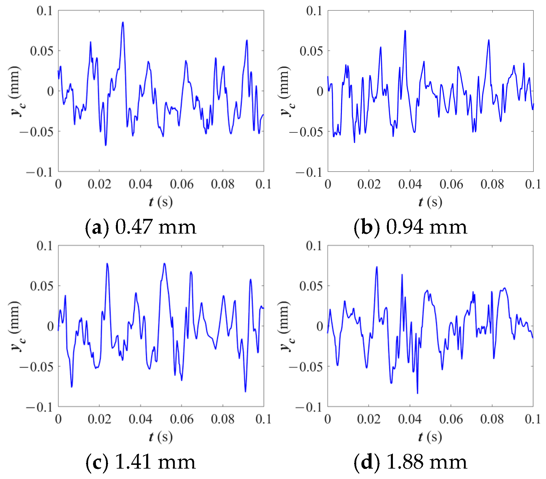
Figure 15 presents a comparison of the radial displacement of the cage across various crack depths. The results notably indicate that crack depth exerts no significant effect on the radial displacement of the cage. This finding suggests that despite the increased stress at the root, the overall displacement of the cage remains stable across different crack depths.
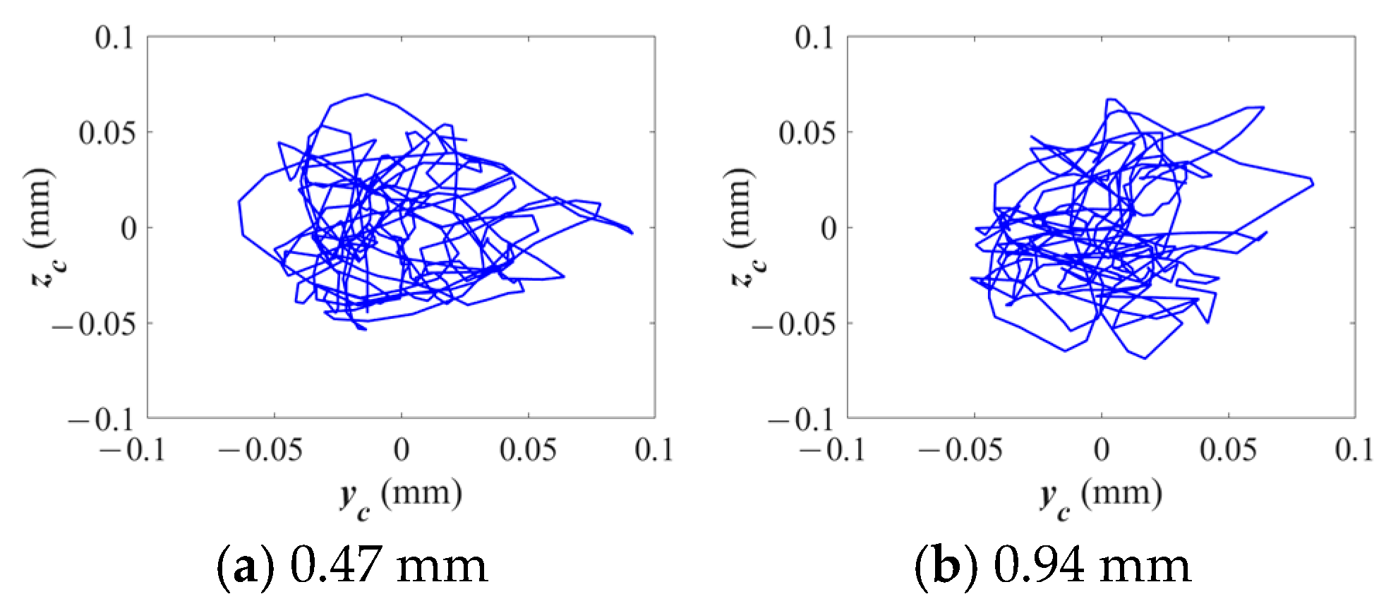
Figure 16 presents the trajectories of the cage centroid under varying crack depth conditions. As the crack depth increases, the movement of the cage’s centroid becomes increasingly chaotic and divergent. At the shallowest crack depth (0.47 mm), the trajectory remains relatively stable; however, as the crack deepens to 1.88 mm, the centroid motion exhibits greater divergence and instability.
As shown in
Table 4, the stress value of the cage also increases as the crack depth increases, which will cause the crack to expand and result in a significant reduction in the crack propagation life.
Figure 17 presents a fitted curve of crack propagation life in relation to crack depth. As illustrated, the life of the cage decreases dramatically as the crack deepens. Initially, the crack propagation rate is high, but it gradually slows as the crack deepens further, indicating a nonlinear relationship between crack depth and propagation rate.
To describe the relationship between the crack propagation life (
) and the crack length (
), the curve was fitted using a cubic polynomial equation of the following form:
where the coefficients are determined as follows:
,
,
,
. The fitting process aligns well with the data points, as illustrated in
Figure 17. This equation effectively captures the decreasing trend in propagation life with increasing crack length, providing a quantitative model for further analysis.
3.2. Effect of Crack Angle on Bearing Dynamic Characteristics
The influence of the crack angle of the cage on the dynamic characteristics of the bearing was studied. The radial load applied to the inner ring of the bearing was set to 3000 N, while the operating speed was set to 6000 r/min. Four conditions of crack angles were selected, and the detailed parameters are shown in
Table 5.
Figure 18 presents the stress distribution at the root of the cage across varying crack angles. The results indicate that as the crack angle increases, the stress at the root decreases. At 0°, the stress at the root is at its maximum, but as the crack angle reaches 75°, it diminishes significantly. This demonstrates that larger crack angles lead to a reduction in stress concentration at the root, which may imply reduced localized damage.
The stress nephogram presented in
Figure 19 provides a visual representation of stress distribution across the cage for varying crack angles. As the crack angle increases, the stress level across the cage diminishes. This demonstrates that although the crack depth remains constant, the angle at which the crack propagates can alter the stress distribution.
The radial displacement of the cage for varying crack angles is presented in
Figure 20. In contrast to the findings regarding crack depth, it can be observed that the influence of crack angle on the radial displacement is negligible or non-existent.
Figure 21 depicts the centroid trajectories of the cage across varying crack angles. As the crack angle increases, the centroid motion shifts from being divergent at lower angles to becoming more concentrated and stable at higher angles. For instance, at 0°, the centroid’s motion is more erratic and dispersed, while at 75°, the motion becomes more controlled and centralized.
As shown in
Table 6, the prediction of the angular propagation life of the pocket crack is shown. At the same crack depth, as the crack angle increases, the horizontal stress on the cage gradually decreases, and the crack propagation life of the cage gradually increases. The crack angle expands at 0° and 15°, while it does not expand at 45° and 75°.
Figure 22 presents the crack angle propagation life fitting curve, illustrating how crack propagation life varies with different angles. This figure highlights that as the crack angle increases, crack propagation life increases as well. At lower angles (0° and 15°), the propagation life is shorter, whereas at larger angles (45° and 75°), the crack propagation life significantly increases.
To describe the relationship between the crack propagation life (
) and the crack angle (
), the curve was fitted using a cubic polynomial equation of the following form:
where the coefficients are determined as follows:
,
,
,
. The fitting process aligns well with the data points, as illustrated in
Figure 22. This equation effectively captures the increasing trend in propagation life with increasing crack angle, providing a quantitative model for further analysis.
3.3. Effect of Crack Location on Bearing Dynamic Characteristics
The finite element models of the side beam crack and the beam crack of the cage were introduced, and the influence of the crack position of the cage on the dynamic characteristics of the bearing was studied. The radial load applied to the inner ring of the bearing was set to 3000 N, while the operating speed was set to 6000 r/min. The detailed parameters are shown in
Table 7.
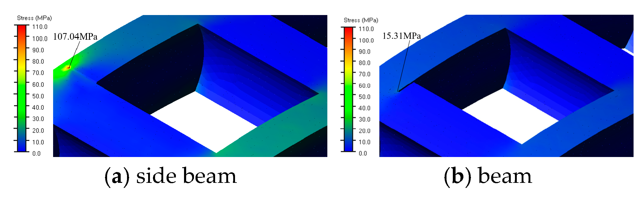
Figure 23 compares the stress at the cage root when the crack is located on the side beam versus the cross beam. The results indicate that the stress at the root is significantly higher when the crack is located on the side beam compared to the cross beam. Cracks on the side beam have a greater impact on the structural strength of the cage. The higher stress on the side beam suggests that it is more susceptible to damage, potentially leading to faster crack propagation and failure.
The stress nephogram in
Figure 24 illustrates how stress is distributed across the cage for different crack locations. The side beam crack exhibits significantly higher stress concentration compared to the cross beam crack, particularly around the root of the crack. A crack on the side beam results in more severe stress distribution, potentially compromising the cage’s ability to function effectively under load.
Figure 25 compares the radial displacement of the cage for cracks located on the side beam versus the cross beam. The results indicate that crack location has no significant effect on the radial displacement of the cage. This suggests that regardless of whether the crack is on the side beam or the cross beam, the overall displacement of the cage remains stable.
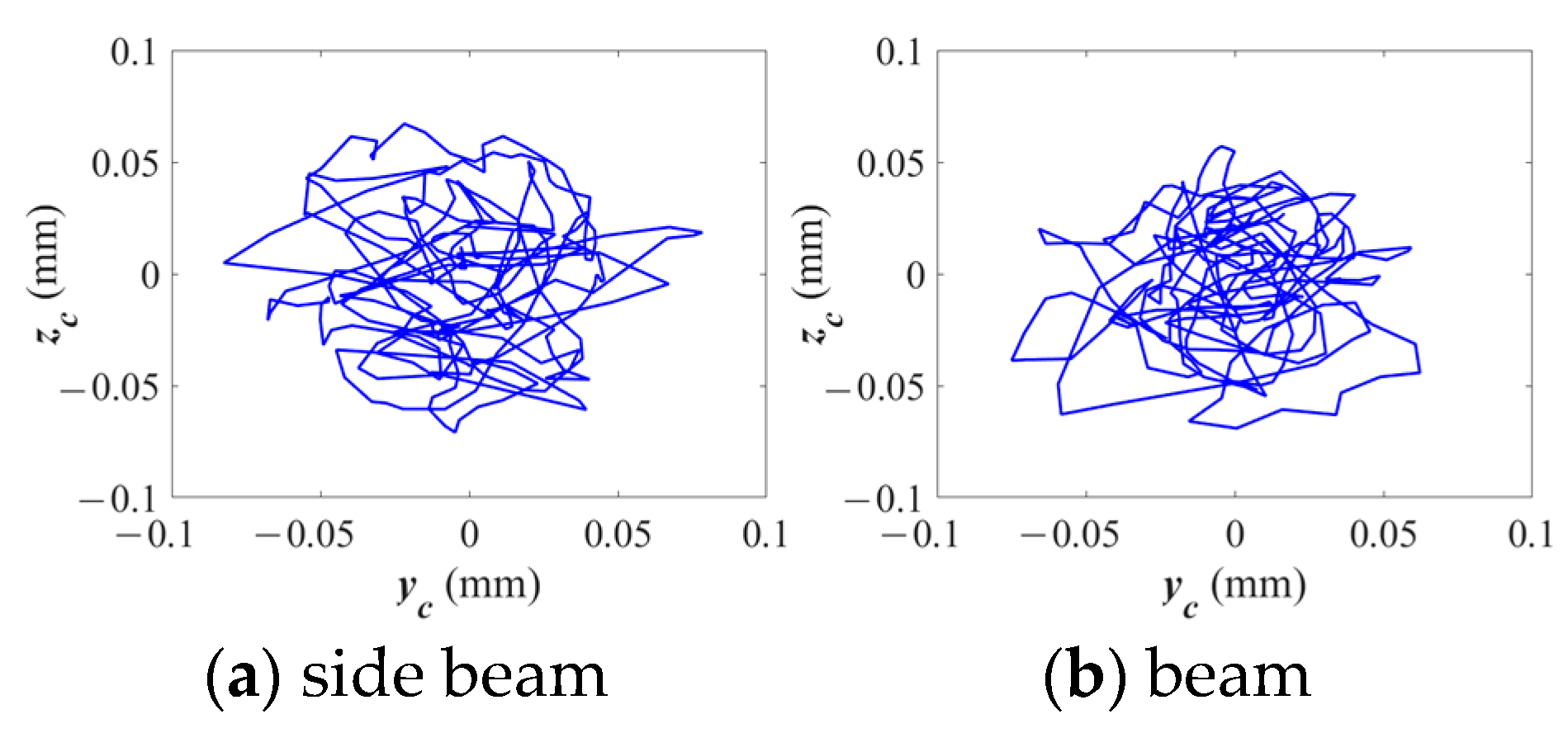
Figure 26 illustrates the centroid trajectories of the cage for different crack locations. The results indicate that a crack located on the side beam causes more divergent centroid motion, while a crack on the cross beam results in a more stable and concentrated trajectory. This demonstrates that a crack on the side beam destabilizes the cage’s motion, resulting in a more chaotic trajectory, which can disrupt the smooth operation of the bearing.
As shown in
Table 8, the propagation life of the pocket crack position is predicted. At the same crack depth, the horizontal stress of the crack at different cage positions is different, resulting in differing crack propagation life of the cage. The propagation life of crack initiation on the side beam is much smaller than that of crack initiation on the beam.


