Abstract
Monolayer (CrN, AlTiN) and bilayer (CrN/AlTiN) coatings are formed on the surface of conventional heat-treated and gas-nitrided X45CrMoV5-3-1 tool steel via Cathodic Arc Physical Vapor Deposition (CAPVD), and the adhesion characteristics and room- and high-temperature wear behavior of the coatings are compared with those of the un-nitrided ones. Scratch tests on the coatings show that the bilayer coating exhibits better adhesion behavior compared to monolayer ones, and the adhesion is further increased in all coatings due to the high load carrying capacity of the diffusion layer formed by the nitriding process. Dry friction tests performed at room temperature reveal that, among ceramic-based coatings, the coating system with a high adhesion has the lowest specific wear rate (0.06 × 10⁻⁶ mm3/N·m), and not only the surface hardness but also the nitriding process is important for reducing this rate. Studies on wear surfaces indicate that the bilayer coating structure has a tendency to remove the surface over a longer period of time. Hot wear tests performed at a temperature (450 °C) corresponding to aluminum extrusion conditions show that high friction coefficient values (>1) are reached due to aluminum transfer from the counterpart material to the surface and failure develops through droplet delamination. Adhesion and tribological tests indicate that the best performance among the systems studied belongs to the steel–CrN/AlTiN system and this performance can be further increased via the nitriding process.
1. Introduction
Aluminum extrusion dies are critical components for the extrusion process. They operate under harsh conditions involving high temperatures and pressures combined with constant contact with hot extruded aluminum, which in turn introduces significant wear-related problems [1,2,3]. As a result, a die material with superior stress- and wear-resistant properties is required. Among the different techniques used in order to improve the surface properties of such components is nitriding. Using such a technique, the formation of nitrides is achieved upon the diffusion and subsequent reaction of nitrogen with the alloying elements of the substrate. Improved properties, such as surface hardness and wear resistance, are thus realized [4,5]. Another method to improve the surface properties in such applications involves the deposition of thin, hard coatings, such as CrN, TiN, TiCN, TiC+TiN, AlTiN and CrN/AlTiN [6]. According to previous investigations, such surface layers lead to significantly improved results with respect to wear resistance [7,8,9]. It is worth noting that among the various hard coatings reported in the literature, CrN is distinguished for its superior oxidation and corrosion resistance and AlTiN is known for its improved high-temperature properties, such as oxidation and wear resistance [10,11,12,13].
Moreover, in the considered applications, nitriding is often employed in combination with surface layer deposition techniques, such as PVD or CVD, which are collectively referred to as duplex treatment. This thermo-chemical surface treatment involves an initial thermal treatment of the substrate (i.e., nitriding), followed by the chemical application of a hard coating [14,15,16]. Through this process, an optimal and gradual change in properties is achieved approaching the surface [17,18]. The multilayered structure provides the coating with improved chemical as well as mechanical resistance compared to single-layered coatings [19]. Additionally, AlTiN coatings applied after steel nitriding exhibit superior properties regarding delamination during the operation phase [20]. Furthermore, TiAlZrN coatings with duplex treatment have been observed to notably improve the wear performance of the substrate material 95-fold [21]. It has also been reported that duplex treatment substantially improves both the interfacial adhesion and the load-bearing capacity of the coatings [22,23].
As stated in our previous investigation, X45CrMoV5-3-1 tool steel (DIN 1.2999) with higher Mo and V contents offers superior wear resistance in comparison to other tool steel grades regarded as candidate materials for the fabrication of aluminum extrusion dies, such as X38CrMoV5-3 (DIN 1.2367), X37CrMoV5-1 (DIN 1.2343) and X40CrMoV5-1 (DIN 1.2344) [24]. Concerning X37CrMoV5-1 tool steel, a beneficial effect of nitriding on the high-temperature wear resistance of multilayer-coated substrates has been reported [25]. Moreover, the results of a comparative study have revealed the superior performance of a duplex coating (CrN/AlTiN) deposited on nitrided X37CrMoV5-1 and X38CrMoV5-3 substrates under conditions simulating the aluminum extrusion process [26,27]. However, the literature is scarce regarding the performance of such thin, hard coatings applied after nitriding on X45CrMoV5-3-1 tool steel. In this study, compared to our previously reported study [9], tribological characterization of CAPVD CrN-, AlTiN-, and CrN/AlTiN-coated X45CrMoV5-3-1 steel is carried out in the case of a nitriding process following heat treatment. The findings have revealed how the diffusion layer formed by the nitriding process provides high adhesion and a low wear rate in the coated materials.
2. Materials and Methods
In this study, DIN 1.2999 (X45CrMoV5-3-1) hot work tool steel with a standard composition of 0.45C, 0.30Mn, 0.30Si, 3.00Cr, 5.00Mo, and 1.00V wt.% is used as a substrate material. Samples of 20 × 20 × 20 mm were taken from the bulk material and all surfaces were polished using 3 µm diamond paste, and an average surface roughness (Ra) of 0.02 µm was attained. The mirror-like surfaces were then washed with alkaline solution, rinsed with distilled water, and dried in warm air. Samples were heat treated according to the following steps from the producer’s data sheet: (i) pre-heating step by step before austenitization, (ii) holding at the austenitization temperature for a specified time, (iii) quenching in air and (iv) multi tempering. During pre-heating, the samples were first kept at 600–650 °C for 60 min and then at 800–850 °C for 60 min. Austenitization was carried out at 1030 °C for 30 min, and after quenching in air, multi-tempering was carried out at three temperatures (585, 560 and 560 °C) for 120 min each.
Conventionally heat-treated samples were gas nitrided at 585 °C for 6 h and cooled with air at a 1.1 bar pressure. It is well known that a brittle compound layer is formed on the surface of gas-nitrided steel substrates, under which a diffusion layer forms with a certain depth [27]. Since the diffusion layer has a higher load carrying capacity compared to the compound layer, this compound layer was removed mechanically and the tool steel with only a diffusion layer on its surface was coated via CAPVD (Hauzer HC404, Netherlands). The coatings deposited on the substrate consist of hard ceramic layers of CrN and AlTiN. The coatings were designed as monolayer (CrN/substrate and AlTiN/substrate) and bilayer coatings (AlTiN/CrN/substrate) using the parameters given in Table 1 by keeping the substrate temperature at 400 ± 50 °C. The coating thickness was designed to be 2 µm for monolayer coatings. For bilayer coatings, a coating consisting of 1 µm AlTiN and 1 µm CrN on the substrate was designed to obtain a total thickness of 2 µm. Following deposition, all thickness values of the coatings were measured via the Calotest method and found to be 1.97 ± 0.18 µm and 2.01 ± 0.11 µm for CrN and AlTiN coatings, respectively. The CrN/AlTiN coating had a 0.93 ± 0.21 µm-thick CrN layer and a 0.96 ± 0.12 µm-thick AlTiN layer.

Table 1.
The coating parameters applied on the heat-treated and nitrided steels.
Heat-treated samples were prepared using standard metallographic procedures and the polished surfaces were etched with a 3% nital solution in order to reveal the microstructural features. Similar procedures were used for the cross-sections of nitrided and coated samples and all samples were characterized using a scanning electron microscope (SEM, Jeol JSM 6060 Akishima, Tokyo, Japan) equipped with an energy dispersive spectrometer (EDS, IXRF, Austin, TX, USA). Coatings on the substrates were also characterized using an X-ray diffractometer (XRD, Rigaku Ultima +, Tokyo, Japan) with Cu-Kα radiation at a scanning rate of 1°·min−1 between 30 and 70°.
For the determination of mechanical properties, hardness measurements were carried out both on the surfaces and cross-sections of nitrided and coated samples. Hardness profiles from the surfaces to core materials were also obtained on the cross-sections. All measurements were performed using an Emcotest Durascan 70 (Salzburg, Austria) micro–macro Vickers hardness tester. During the measurements, two load values were selected; 0.01 kgf was used for hardness measurements of the surface and cross-sections and 10 kgf was used for both the diffusion layer and core material. Average values and standard deviations were calculated after multiple measurements.
Adhesion of the coatings was assessed by means of scratch testing, specifically a CSM Revetest Scratch Tester (CSEM, Neuchâtel, Switzerland). A diamond tip with a radius of 200 μm and an angle of 120° was utilized at a travel speed of 10 mm/min under a loading rate of 100 N/min to determine the critical load (Lc) at which the first coating failure occurred. The range of progressively increased loads during scratch testing was between 0 and 120 N. Following scratch testing, the specimens were examined stereomicroscopically to study the scratch paths at a low magnification. Subsequently, SEM/EDS (Jeol JSM-5310 Akishima, Tokyo, Japan) analysis was employed to identify the coating failure mode.
Tribological tests were carried out at both room temperature (RT) and elevated temperature (HT) using two different set-ups. A commercial “ball-on-disc”-type tribometer (Nanovea M/NI/1-E, Madrid, Spain) was used for RT tests and an alumina ball with a diameter of 5 mm was used as a counterpart material for a total sliding distance of 150 m under a 20 N load at a rotating speed of 0.08 m/s (150 rpm). The elevated temperature tests were performed using a home-made tribometer with a “block-on-cylinder” configuration at 450 °C, simulating aluminum extrusion conditions (Figure 1). The counterpart material was selected as the AA6080 alloy with a cylindrical geometry (ϕ 100 mm × 30 mm), and tribological interactions were provided under a 70 N load and a 0.27 m/s (53 rpm) sliding speed for a total sliding distance of 2000 m. The tribological test results were evaluated using (i) diagrams of coefficient of friction (COF) versus sliding distances, (ii) calculation of specific wear rates (W), and (iii) examinations of worn surfaces via SEM and an optical profilometer (Nanovea PS50, Spain). The profilometric measurements provide a sensitive determination of volume losses (mm3) after wear tests. The Archard equation was used for the calculation of specific wear rates (mm3/N·m), where the volume loss is divided by the load (N) and sliding distance (m).
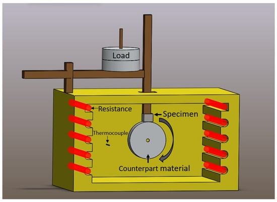
Figure 1.
A model showing the hot wear configuration used.
3. Results
3.1. Microstructural Characterization of Heat-Treated and Nitrided Steel
In Figure 2, the image of the etched structure of the heat-treated tool steel used as a substrate material reflects typical dispersed globular carbides embedded in a tempered martensitic matrix. EDS maps indicate that these carbides are Mo-rich carbides (M6C) with a composition of 17.61 Mo, 76.82 Fe, and 5.57 C wt.%. After gas nitriding, a compound layer (~12 µm) and a diffusion layer (~90 µm) are formed on the surface of the tool steel, as shown in Figure 3. EDS analysis of compound layer reveals its composition as 80.77 Fe, 8.34 Mo, 2.51 Cr, 0.58 V, and 7.80 N wt.%. It is essential to remove this brittle compound layer to provide a good adherence of the coating; in addition, it does not contribute to load carrying during tribological interactions [19]. In this study, the compound layer formed on the surface is removed by mechanical grinding for this purpose. As can be seen in Figure 3, grain boundary nitrides containing Fe and Mo are formed in the diffusion layer and their composition is determined as 46.75 Fe, 46.98 Mo, 2.26 Cr, 1.91 V, 1.12 N, and 0.98 C wt.% via multi-EDS analyses.
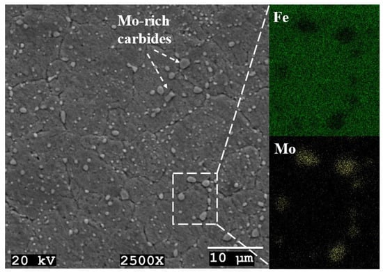
Figure 2.
Microstructure of heat-treated steel used as a substrate material and elemental mapping of carbides inside the area marked by the dashed box.
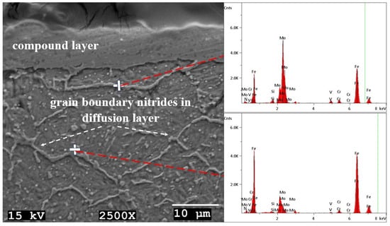
Figure 3.
SEM image showing the cross-section of the nitrided steel (left). EDS spectra corresponding to spot analysis conducted on the sites indicated by the white crosses (right).
3.2. Characterization of Coatings
In Figure 4, SEM images of the coatings (CrN, AlTiN and AlTiN/CrN) deposited on the diffusion layer of heat-treated and nitride tool steels are provided. Homogenous and continuous PVD coatings with a ~2 µm thickness are achieved, and the coatings have no defects such as pores, cracks, and delamination. EDS maps acquired at the area indicated by the dashed boxes shown in Figure 4, denote the coatings formed on the surfaces. Due to the low signal from nitrogen, data collection took longer; thus, its map is not included in the figure, and only the metals (Cr, Al and Ti) present in the coatings and iron (Fe) in the matrix are mapped. Multi-EDS analyses revealed the elemental compositions as 0.51 Cr and 0.49 N at.% for the monolayer CrN coating and 0.33 Al, 0.18 Ti, and 0.49 N wt.% for the monolayer AlTiN coating. The Cr:N ratio is calculated as 1.04 and the (Al+Ti):N ratio is calculated as 1.04, indicating that the target metal/nitrogen (Me:N) ratio of ~1 is achieved. In the bilayer coating, chemical compositions are determined similarly for each layer and the calculated Me:N ratios are 1.01 and 1.03 for CrN and AlTiN coatings, respectively. The XRD spectra given in Figure 5 show the presence of ceramic-based coatings like CrN (ICDD 11-0065) and AlTiN (ICDD 71-5864) on the substrates, which is in agreement with previous studies on similar coatings [9,28,29].
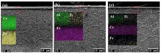
Figure 4.
SEM images of the heat-treated, nitride, and coated samples: (a) CrN, (b) AlTiN and (c) CrN/AlTiN coatings.
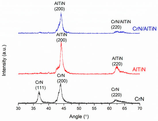
Figure 5.
X-ray diffraction spectra for the heat-treated, nitrided and coated steels.
In this section, hardness data are also evaluated for each coating/substrate both on the surface and in the cross-section. Figure 6 shows the hardness profiles at different loads through the cross-sections depending on the matrix structure. In monolayer coatings, the CrN coating exhibits a lower hardness value (2038 ± 115 HV0.01) compared to that of the AlTiN coating (2270 ± 110 HV0.01). The hardness values of AlTiN and CrN layers in the bilayer coating are in the same range as the ones obtained for monolayer coatings. In the diffusion layer, a maximum hardness of 802 ± 32 HV10 is attained just below the coatings down to a 100 µm depth. It is clear that the diffusion layer hardness values have a decreasing tendency due to the decrease in nitrogen content (Figure 6). Multiple hardness measurements below the diffusion layer indicate that the heat-treated tool steel with a tempered martensitic structure has a hardness of 508 ± 22 HV10. It is clear that a functionally graded structure in terms of hardness is attained, since the hardness values keep decreasing from the coating to the substrate material. The obtained surface hardness values are listed in Table 2. As can be seen from the table, the bilayer coating provides a higher surface hardness (2263 ± 125 HV0.01) compared to that of monolayer coatings. In an earlier study [9], similar coatings were deposited on the same substrate tool steel (X45CrMoV5-3-1) without the nitriding process. Compared to the present study, although similar monolayer/bilayer coatings have been obtained, the hardness values are lower than the ones listed in Table 2. Since the nitriding process causes the formation of a diffusion layer which has a high load carrying capacity, the surfaces have a higher resistance to indentation. The presence of a diffusion layer acts as an interface between the coating and the substrate, resulting in improved hardness values, and, as compared to the data reported in [9] for the un-nitrided case, surface hardness increases of 15%, 17% and 16% are achieved for the CrN/substrate, AlTiN/substrate and AlTiN/CrN/substrate, respectively.
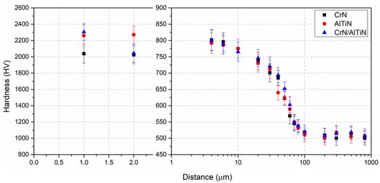
Figure 6.
Hardness profiles of the heat-treated, nitride, and coated steels.

Table 2.
Surface hardness values of the coating/substrate.
3.3. Adhesion Characteristic of the Coatings
Figure 7 shows the variation in the acoustic emission signal with respect to the load at which the first coating failure occurs. The first peak represents the critical load (LC) where the initial coating cracking failure occurs. Table 3 presents all the findings of the scratch tests, comparing the data for un-nitrided and nitrided coatings, and clearly demonstrates the enhanced adhesion due to nitriding. An SEM image showing the scratched surface of the nitrided and CrN-coated steel is provided in Figure 8. In the initial stage, as the increasing force causes the formation of the first acoustic emission peak at 9.2 N, angular cracks appear at the edges of the scratch (Figure 8a). Depending on the forward movement of the tip, (i) the pre-existing microcracks grow and become denser, and (ii) semicircular microcracks form and extend along the width of the scratch (Figure 8b). As seen in Figure 8c, the semicircular microcracks coexist with buckling and chipping at the end of the scratch. An SEM/EDS study is carried out for the first coating failure, and the findings indicate the attachment of the CrN coating to the substrate. The chromium composition (wt.%) is high inside the scratch track, revealing partial removal of the coating by the spherical tip. Microcracks evolve under a progressively increased force, causing pores as a discontinuity in the coating. EDS data for the area inside the pores indicate a significant reduction in nitrogen, while iron is highly prevalent (Figure 9).
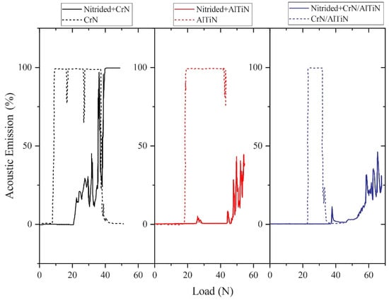
Figure 7.
The variation in acoustic emission with respect to load.

Table 3.
LC values attained via a scratch test for the coated samples.

Figure 8.
(a) Initial stages of the scratch test in which the angular microcracks form, (b) formation of semicircular microcracks, and (c) the endpoint of the scratch on the surface of heat-treated, nitrided, and CrN-coated steel.
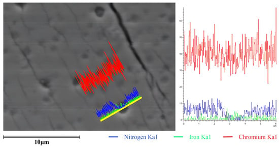
Figure 9.
Line scan (yellow line) on porous surface of the heat-treated, nitrided and CrN-coated sample.
When considering the scratch test track of the heat-treated, nitrided and AlTiN-coated sample, it is observed that the track initially exhibits a low depth and width, corresponding to an intact coating at the early stages of the test. Angular microcracks form on both the upper and lower edges of the scratch when the first acoustic emission peak is monitored. Microcracks are observable at high magnifications. Additionally, both coating chipping and lateral deposition of the coating by the diamond tip are observed at the end of the scratch track. As depicted in Figure 10, there are no significant compositional changes in both the aluminum and titanium inside and outside the scratch path, indicating that the AlTiN coating is only slightly removed by the spherical tip.
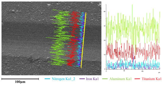
Figure 10.
Line scan (yellow line) transverse to the scratch track on the heat-treated, nitrided and AlTiN-coated surface.
The observations on the scratch track formed on the CrN/AlTiN coating can be summarized as follows: (i) there is no damage due to the spherical tip at the initial stage of the test, (ii) semicircular microcracks appear as the force reaches the LC value, indicating the propagation of pre-existing angular cracks which are linked across the width of the track, (iii) buckling occurs due to the compressive stresses generated in front of the diamond tip and the presence of interfacial cracks, and (iv) lateral deposition of the coating and chipping occur due to previous buckling failures. The SEM/EDS data provided in Figure 11 can help to define the coating failure mode. The areas of AlTiN and CrN coatings can be distinguished by their contrast, with the CrN coating appearing in bright contrast. Additionally, spectra 2 and 3 correspond to the chemical composition of the AlTiN and CrN coatings on the surface, respectively. Such compositional findings indicate that the bilayer coating is not entirely removed by the motion of the spherical tip. Furthermore, the material that drifted to the scratch edge includes mainly chromium and iron, which suggests that both the CrN coating and the steel substrate are removed by the diamond tip during the test. Consequently, both chromium and iron (wt.%) are detected at the end of the scratch, primarily in the chipped material.
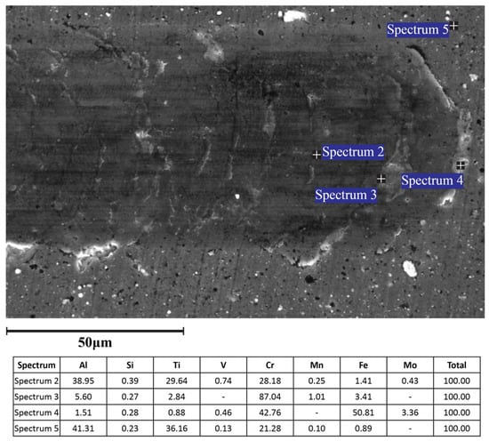
Figure 11.
Spot analysis at the end of the scratch track on the heat-treated, nitrided and CrN/AlTiN-coated surface.
Atomic force microscopy (AFM, Explorer, Topometrix, Santa Clara, CA, USA) studies were carried out to acquire 3D projections of the scratch tracks and to measure the maximum depths of the scratch paths at the first coating failure and at the endpoint of the scratch. The data obtained via AFM measurements are listed in Table 4. It is a fact that the coating has not been entirely removed at the first coating failure, since the maximum depth at LC is lower than the coating thickness (~2 μm) for all specimens. The 3D projection given in Figure 12a shows the first coating failure for the heat-treated, nitrided and CrN-coated surface by scratching, with the maximum depth measured as 1.18 μm. This depth is lower than both the total thickness and the previous measurement of the un-nitrided and CrN-coated specimen (Table 4). Following the first coating failure, a series of measurements indicate that the maximum depth increases to 1.85 μm (Figure 12b).

Table 4.
AFM data for the measured maximum depths of the scratch tracks.
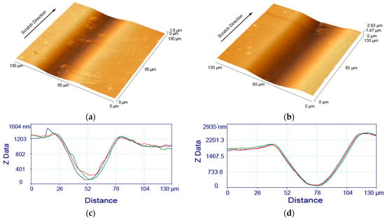
Figure 12.
AFM images along a scratch on the heat-treated, nitrided and CrN coated steel, (a) where the first coating failure occurs and (b) after coating failure is observed. (c,d) depict corresponding line scans (three scans per scratch) of (a,b) respectively.
By considering AFM data on the AlTiN-coated specimen, the scratch test track appears to have a low depth and width during the early stages. The depth measured is 0.32 μm, which is lower than the total thickness (2 μm) as seen in the 3D image given in Figure 13a, indicating that the coating remains intact. After the first acoustic emission peak is monitored, the depth increases to 0.64 μm, which is still shallow, and the coating has only been superficially removed by the diamond tip (Figure 13b). The scratch path for the CrN/AlTiN-coated specimen is also examined via AFM, and the findings show that the measured depths are 0.45 μm and 1.1 μm for the initial stage and after the first failure, respectively. The data reflect that the coating has not been entirely removed by the diamond tip at the midpoint of the scratch track.
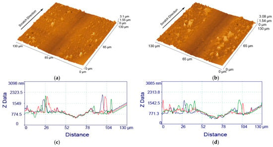
Figure 13.
AFM images along a scratch on the heat-treated, nitrided and AlTiN coated steel, (a) where the first coating failure occurs (b) after coating failure is observed. (c,d) depict corresponding line scans (three scans per scratch) of (a,b) respectively.
3.4. Wear Performance of the Coatings
In Figure 14, coefficient of friction (COF) versus sliding distance graphs are given for the coated tool steels after the wear test performed at RT and compared to those of the Al2O3 counterpart material. Considering the range of COF values, all graphs reveal three stages: (i) a running-in stage, (ii) a transition stage and (iii) a steady-state stage. As well known, it is inevitable that the COF increases in the running-in stage due to the deformation of surface roughness and multi-scratching due to the motion of free particles on the surface causing a polishing effect [30,31,32]. The COF values reach a maximum in the transition stage since the surface roughness is decreased and the new surface is subjected to adhesion forces [9,24,27]. In the steady-state stage, friction forces decrease depending on the lack of adhesion of worn particles to the polished surface, the deformation of roughness and the decrease in ploughing, which in turn cause an oscillation in COF values and a steady value is obtained [24,33]. These stages are observed at different sliding distances for the studied surfaces with different surface characteristics. In CrN-coated tool steel, which has the lowest surface hardness, the running-in stage lasts for the first 5 m of the total sliding distance and the COF value reaches up to 0.27. For this material, the transition stage is observed at a 5–10 m distance and the COF value increases to 0.29. The steady-state stage starts after 10 m and the obtained COF value is 0.28, which is higher than the COF value (0.22) obtained for the same coating without the nitriding process and tested under a similar friction condition [9]. As a result of the formation of a diffusion layer between the coating and substrate material due to nitriding, not only a higher surface hardness but also a higher LC value is attained. Depending on the higher surface hardness caused by nitriding, the shear stress increases during contact, which causes higher COF values [24,33,34]. The running-in stage lasts for the first 10 m of the total sliding distance in the AlTiN-coated tool steel, which has a higher surface hardness than the CrN-coated one, and the COF values linearly increase, reaching 0.31 in the transition stage (10–25 m). In the steady-state stage, COF values of 0.31–0.33 were observed due to the increase in shear stress, and this range is higher than the one (0.27) reported for the un-nitrided AlTiN-coated tool steel under the same tribological condition [9]. In the bilayer coating (CrN/AlTiN), the COF values are higher in all stages compared to the single-layer coatings. For this coating, (i) a linear increase is observed in the first 8 m (running-in stage), (ii) a transition stage is observed between 8 and 40 m, with a COF value reaching a maximum of 0.40, and (iii) COF values vary between 0.36 and 0.40 in the steady-state stage. Among all the coated tool steels, the bilayer coating with the highest surface hardness value exhibits a higher COF value at all stages due to the decreased contact area and increased shear stresses. Compared to the un-nitrided case with a 0.38 COF value in steady-state stage [9], this coating has a higher COF value due to the presence of a diffusion layer which increases the surface hardness.
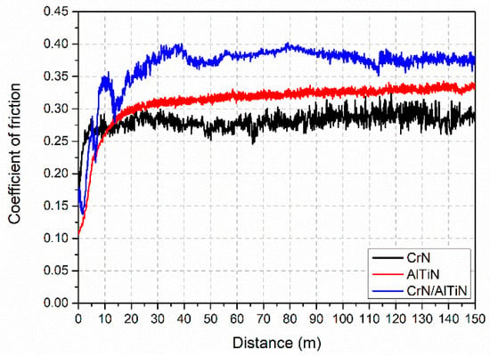
Figure 14.
Variation in friction coefficient values with respect to distance at RT for the heat-treated, nitrided and coated steels.
The wear tracks were characterized using a 3D profilometer after the tribological tests at RT, and both the width and depth profiles, which are used for the determination of the volume loss, are displayed. In Figure 15a, the profilometric projection of the worn surface for CrN-coated tool steel is shown, and the regions away from the wear track exhibit the coated surface, which is continuous and homogenous. A line is drawn through the wear track at the deepest point in order to obtain the width and depth 2D profile, which is given in Figure 15b. The width of the wear track is about 280 µm and the track has fine abrasive scratches parallel to the motion of the counterpart material and regions with deep grooves. The track depth (ΔZ) measured after the friction test is decisive in determining whether the coating is removed or not. In CrN-coated tool steel, ΔZ is measured as 2.75 µm and indicates that the coating is partially removed, especially at the center line of the wear track. As can be seen in the projection (Figure 15a), a material pile-up due to the debris removed from the surface by the counterpart is present at a certain height along the lateral direction of the wear track. Although the AlTiN coating with a higher surface hardness than the CrN one reveals similar wear-track characteristics (Figure 16a), the obtained wear track given in Figure 16b is both narrower (~200 µm) and shallower (~1.75 µm) as a function of the lower contact area due to the higher hardness [32,33]. In the bilayer coating, ΔZ is measured as ~1 µm, indicating that the coating is still present on the surface (Figure 17). This result is expected since the highest surface hardness is obtained due to the presence of functionally graded hardness values.
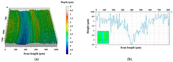
Figure 15.
Three-dimensional image showing the wear track formed on the heat-treated, nitrided and CrN-coated steel (a) and its profile (b).
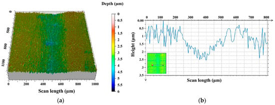
Figure 16.
Three-dimensional image showing the wear track formed on the heat treated, nitrided and AlTiN-coated steel (a) and its profile (b).
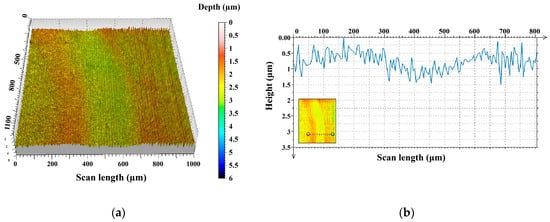
Figure 17.
Three-dimensional image showing the wear track formed on the heat treated, nitrided and CrN/AlTiN-coated steel (a) and its profile (b).
Volume losses (mm3) are determined using the profiles, and specific wear rates are calculated by dividing these values by the nominal force (N) and sliding distance (mm). Table 5 shows both the calculated specific wear rates of the studied coatings and those reported for un-nitrided tool steels tested under similar friction conditions [9]. The calculated wear rates reflect a decreasing tendency upon an increase in the surface hardness, and the rates can be further reduced by nitriding. As well known, the elastic modulus of each layer in bilayer/multi-layer coating systems affects the load carrying capacity. Considering the stress distribution under nominal loading, in the functionally graded coatings, in terms of hardness, the maximum stress is carried from the substrate to the top layer, resulting in retarded plastic deformation of the substrate and increased adhesion between the substrate and coating. This increase in adhesion provides a higher structural integrity by avoiding the fracture of the coating under the nominal load and causing a decrease in volume loss [27,35]. In this study, a diffusion layer harder than the matrix is formed by nitriding, and depositions of ceramic-based hard coatings with different elastic moduli are provided; therefore, the lowest specific wear rate is attained for the bilayer coating in which the top layer (AlTiN layer) has a higher elastic modulus compared to the CrN layer.

Table 5.
Wear rates for RT tests of the studied steels.
SEM images of the worn surfaces of coated tool steels after the dry friction tests are given in Figure 18, Figure 19 and Figure 20. In general, all wear tracks have a smooth characteristic, and their widths are in agreement with the profilometric measurements. Movement of the counterpart material causes failure of the coatings and detachment occurs; the resulting free wear debris are distributed on the surface and some are accumulated along the wear tracks. As seen in Figure 18a, the track center exhibits abrasive scratches, and adhesive layers are present along the wear track on the CrN-coated surface. The wear debris that are detached from the coating under the applied load act as hard free bodies and cause abrasive scratches at the deepest point of the wear track. It is also inevitable that an adhesive layer structure is formed due to cold welding of debris along the wear track. Two-dimensional body contact changes to three-dimensional body contact due to the presence of wear debris, causing deep scratches along the wear track. The EDS profile taken across the track confirms the performance of the coating during tribological interactions. As seen in Figure 18b, although elements (Cr, N) of the coating appear at the sides of the track, the profile shows that there is a Fe-rich zone at the center of the track, indicating removal of the coating. The presence of coating elements at the sides is evidence that the coating is still present in narrow areas. The profiles of Cr and N indicate that the amounts of these elements are considerably decreased as a result of progressing 3D body contact throughout the wear depth.
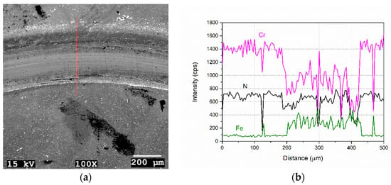
Figure 18.
SEM image of the worn surface of CrN-coated tool steel (a) and corresponding profiles acquired across the red line (b).
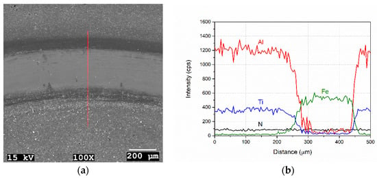
Figure 19.
SEM image of the worn surface of AlTiN-coated tool steel (a) and corresponding profiles acquired across the red line (b).
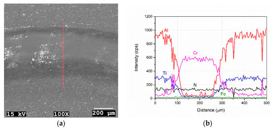
Figure 20.
SEM image of the worn surface of CrN/AlTiN-coated tool steel (a) and corresponding profiles acquired across the red line (b).
Compared to the CrN coating, less abrasive wear is observed in the wear track of the AlTiN coating (Figure 19a), and the profiles given in Figure 19b reflect that the coating is more persistent. On the other hand, in the wear track of the bilayer coating, rather than abrasive scratches, a polishing effect appears to be dominant, and debris are present as attached particles in the track (Figure 20a). Considering the elemental profiles given in Figure 20b, although the AlTiN coating is removed during the tribological interaction, the CrN coating is still present along the track and no Fe-rich zones (indicating the substrate material) are observed. These findings reveal that the bilayer coating has the highest load carrying capacity compared to the single-layer coatings, and since all wear tests were applied under the same conditions, it is clear that the bilayer coating has the potential to retard wear at longer sliding distances/times. Studies performed under similar test conditions on such a bilayer coating for the un-nitrided case have shown that deep grooves form in the wear track and the coating is completely removed by continuous volume loss at 4 µm below the surface [9]. The results of this study on the bilayer coating emphasize the requirement of nitriding for increasing the load carrying capacity, which is an important factor for improving wear resistance.
The variation in COF values with the respect to sliding distance is shown in Figure 21 for the high-temperature test performed using a block-on-cylinder setup. The results reveal three stages similar to the RT data for all coatings. The run-in stage lasts for the initial 70 m of the sliding distance. A transition stage is observed in the 70–250 m range and is followed by the steady-state stage for the remaining part of the total sliding distance. The COF values for all coatings are above “1” due to the adhesion of aluminum on the surface. As a result of this, the tribological pair changes to aluminum-coated steel [36]. Such high values were also observed for un-nitrided and similar coated steels in high-temperature tests performed under similar conditions [9]. In addition, addition increases in the case of the interaction between the AlTiN coating and the aluminum-based counterpart material [37]. Although the load carrying capacity is increased by nitriding, the high-temperature wear performance is dominated by the continuous aluminum adhesion on the surface. Under test conditions, fluctuation in the COF values is inevitable due to the oxidation of aluminum and its adherence to the surface followed by the reoxidation and delamination during sliding. Such an effect is reflected especially in the COF values of AlTiN and CrN/AlTiN coatings at their transition stages, and the COF values have a decreasing tendency. In the steady-state stage, the fluctuation in COF values can be attributed to both the formation of an adhered aluminum layer and its failure due to both oxidation and strain hardening under an applied load, which continues in a cycle during the test [4,9,19]. When the steady-state-stage COF values are considered, a difference in the performance of the coatings can be seen. The AlTiN coating has higher COF values compared to the CrN coating, which is the result of aluminum–aluminum interactions [36].
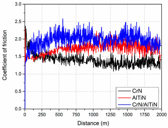
Figure 21.
Variation in friction coefficient values with respect to distance at HT for the heat-treated, nitrided and coated steels.
Since the adhered layer can be seen by the naked eye after high-temperature test, the surfaces were dipped into NaOH solution to remove the adhered aluminum layer for SEM investigations to reveal the worn surfaces. The general view of the worn surface of the CrN-coated tool steel tested at HT is shown in Figure 22a and the SEM image reveals that the adhered aluminum layer is still present despite NaOH application. The worn surface also reflects typical droplet delamination, which is a characteristic failure of PVD coatings (Figure 22b). Such a failure occurs via aluminum diffusion to the droplet boundaries of the CrN coating, and the boundaries are weakened by chemical reactions during the tribological interaction [2,18,38]. Although some cracks were observed on the worn surface of the CrN coating that was not nitrided under similar conditions [9], no cracks are present in this study. As well known, significant stress is present between the metal and the ceramic coating at high temperatures as a result of their different thermal expansion coefficients, which causes the cracks in the coating [39,40]. Via nitriding of tool steel, this difference in the thermal expansion coefficients can be reduced; as a result of this, the stress level can be decreased [41]. In addition, nitriding also helps to decrease the plastic deformation ability of the substrate material, and failure of the coating is retarded by the formation of a diffusion layer that provides a higher load carrying capacity [42,43]. EDS studies performed on the worn surfaces confirm our understanding of the functionality of the coatings under tribological interactions. The EDS data (73.62 Cr, 6.59 Al, 9.52 N, 10.27 O wt.%) of the red marked spot in Figure 22b indicate the presence of elements (Cr and N) in the coating at the region where droplet delamination occurs, and the presence of both Al and O elements in the data is related to the adhered aluminum layer. On the worn surface of the AlTiN coating, given in Figure 23a, oxidation of the adhered aluminum layer and its detachment marked in a red frame, followed by re-adherence, can be clearly seen. The dominant failure is droplet delamination (Figure 23b), and the EDS data (44.76 Al, 27.92 Ti, 21.05 N, 6.27 O wt.%) at the red marked spot reveal that the coating is still stable on the surface. Considering the examination of the general worn surface (Figure 24a), similar surface characteristics and failure modes are observed for the CrN/AlTiN coating and a stable bilayer coating exists according to EDS data (43.56 Al, 30.12 Ti, 0.82 Cr, 21.18 N, 4.32 O wt.%) taken at the red marked spot in Figure 24b.
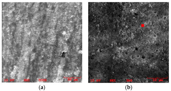
Figure 22.
(a) An SEM image showing the worn surface of the heat-treated, nitrided and CrN-coated steel and (b) observed droplet delamination.
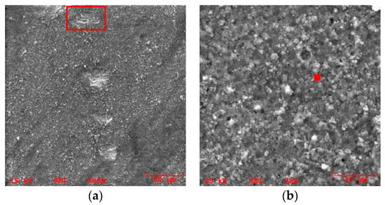
Figure 23.
(a) An SEM image showing the worn surface of the heat-treated, nitrided and AlTiN-coated steel and (b) observed droplet delamination.
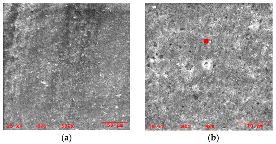
Figure 24.
(a) An SEM image showing the worn surface of the heat-treated, nitrided and CrN/AlTiN-coated steel and (b) observed droplet delamination.
4. Conclusions
In this study, following our previous studies, we examined how the room-temperature and high-temperature wear performance of conventional heat-treated and X45CrMoV5-3-1 hot work tool steel coated via CAPVD varies depending on the nitriding process. By considering un-nitrided and coated surfaces, since they provide a diffusion layer (~90 μm) with a high load carrying capacity, the surface hardness and coating adhesion could be increased simultaneously with single (CrN, AlTiN) and bilayer coatings (CrN/AlTiN) applied via CAPVD after the nitriding process. The obtained LC values conform our understanding of the effect of the presence of a diffusion layer and the coating type on the performance of the coatings. The general trend is that higher LC values are achieved as a result of the presence of the diffusion layer and the relatively high shear strength provided by the bilayer coating. Although the failure pattern of CrN coatings indicates a tendency to form angular/semicircular cracks on the surface during scratching, buckling and chip formation are also observed in AlTiN and CrN/AlTiN coatings. At room temperature and under dry friction test conditions, it is observed that as the surface hardness increases, the COF values during the steady-state stage increase and the wear rates decrease for the coated steels. The CrN/AlTiN coating has the highest COF value (0.36–0.40) and the lowest wear rate (0.06 × 10⁻⁶ mm3/N·m). Conducting nitriding before coating causes a decrease in all wear rates, and the tool surface covered with a bilayer coating shows a superior performance in tribological interactions. Hot wear tests, where aluminum extrusion conditions can be met, have shown the superior performance of the bilayer coating, which leads to lower wear losses and a more stable film on the surface under tribological conditions.
Author Contributions
Conceptualization, Ş.H.A., Ş.P. and A.D.Z.; methodology, G.A.Ç. and K.F.; validation, G.A.Ç., K.F. and E.K.; investigation, G.A.Ç., K.F. and E.K.; resources, Ş.H.A., Ş.P. and A.D.Z.; data curation, E.K., Ş.H.A., G.A.Ç., K.F. and A.D.Z.; writing—original draft preparation., G.A.Ç., K.F. and E.K.; writing—review and editing, Ş.H.A., A.D.Z. and Ş.P.; visualization, G.A.Ç., K.F. and E.K.; supervision, Ş.H.A., Ş.P. and A.D.Z. All authors have read and agreed to the published version of the manuscript.
Funding
This research received no external funding.
Data Availability Statement
The data presented in this study are available on request from the corresponding author. The data are not publicly available due to privacy reasons.
Acknowledgments
Anna D. Zervaki would like to acknowledge the support of MIRTEC SA, 1st Industrial Area of Volos, Greece, for providing access to the scratch tester, and to the University of Thessaly, Department of Mechanical Engineering, Laboratory of Materials in Volos, Greece, for the fruitful collaboration.
Conflicts of Interest
The authors declare no conflicts of interest.
References
- Bakhtiani, T.; El-Mounayri, H.; Zhang, J. Numerical simulation of aluminum extrusion using coated die. Mater. Today Proc. 2014, 1, 94–106. [Google Scholar] [CrossRef]
- Björk, T.; Westergård, R.; Hogmark, S. Wear of surface treated dies for aluminium extrusion—A case study. Wear 2001, 249, 316–323. [Google Scholar] [CrossRef]
- Birol, Y. Sliding wear of CrN, AlCrN and AlTiN coated AISI H13 hot work tool steels in aluminium extrusion. Tribol. Int. 2013, 57, 101–106. [Google Scholar] [CrossRef]
- Birol, Y. Analysis of wear of a gas nitrided H13 tool steel die in aluminium extrusion. Eng. Fail. Anal. 2012, 26, 203–210. [Google Scholar] [CrossRef]
- Akhtar, S.S.; Arif, A.F.M.; Yilbas, B.S. Gas nitriding of H13 tool steel used for extrusion dies: Numerical and experimental investigation. Mater. Manuf. Process. 2017, 3, 158–177. [Google Scholar]
- Dobrzanski, L.; Polok, M.; Panjan, P.; Bugliosi, S.; Adamiak, M. Improvement of wear resistance of hot work steels by PVD coatings deposition. J. Mater. Process. Technol. 2004, 155–156, 1995–2001. [Google Scholar] [CrossRef]
- Björk, T.; Bergström, J.; Hogmark, S. Tribological simulation of aluminium hot extrusion. Wear 1999, 224, 216–225. [Google Scholar] [CrossRef]
- Pellizzari, M. High temperature wear and friction behaviour of nitrided, PVD-duplex and CVD coated tool steel against 6082 Al alloy. Wear 2011, 271, 2089–2099. [Google Scholar] [CrossRef]
- Aktaş Çelik, G.; Fountas, K.; Atapek, Ş.H.; Kamoutsi, E.; Polat, Ş.; Zervaki, A.N. Investigation of adhesion and tribological performance of CrN-, AlTiN-, and CrN/AlTiN-coated X45CrMoV5-3-1 tool steel. J. Mater. Eng. Perform. 2023, 32, 7527–7544. [Google Scholar] [CrossRef]
- Lukaszkowicz, K.; Dobrzanski, L.; Kokot, G.; Ostachowski, P. Characterization and properties of PVD coatings applied to extrusion dies. Vacuum 2012, 86, 2082–2088. [Google Scholar] [CrossRef]
- Al-Bukhaiti, M.A.; Al-Hatab, K.A.; Tillmann, W.; Hoffmann, F.; Sprute, T. Tribological and mechanical properties of Ti/TiAlN/TiAlCN nanoscale multilayer PVD coatings deposited on AISI H11 hot work tool steel. Appl. Surf. Sci. 2014, 318, 180–190. [Google Scholar] [CrossRef]
- Mo, J.L.; Zhu, M.H. Sliding tribological behaviors of PVD CrN and AlCrN coatings against Si3N4 ceramic and pure titanium. Wear 2009, 267, 874–881. [Google Scholar] [CrossRef]
- Mo, J.L.; Zhu, M.H. Tribological oxidation behaviour of PVD hard coatings. Tribol. Int. 2009, 42, 1758–1764. [Google Scholar] [CrossRef]
- Adamiak, M.; Dobrzański, L. Microstructure and selected properties of hot-work tool steel with PVD coatings after laser surface treatment. Appl. Surf. Sci. 2008, 254, 4552–4556. [Google Scholar] [CrossRef]
- Björk, T.; Westergård, R.; Hogmark, S.; Bergström, J.; Hedenqvist, P. Physical vapour deposition duplex coatings for aluminium extrusion dies. Wear 1999, 225–229, 1123–1130. [Google Scholar] [CrossRef]
- Rodríguez-Baracaldo, R.; Benito, J.A.; Pichi-Cabrera, E.S.; Staia, M.H. High temperature wear resistance of (TiAl)N PVD coating on untreated and gas nitrided AISI H13 steel with different heat treatments. Wear 2007, 262, 380–389. [Google Scholar] [CrossRef]
- Hardell, J.; Prakash, B. Tribological performance of surface engineered tool steel at elevated temperatures. Int. J. Refract. Hard Met. 2010, 28, 106–114. [Google Scholar] [CrossRef]
- Kalin, M.; Jerina, J. The effect of temperature and sliding distance on coated (CrN, TiAlN) and uncoated nitrided hot-work tool steels against an aluminium alloy. Wear 2015, 330–331, 371–379. [Google Scholar] [CrossRef]
- Birol, Y.; Yuksel, B. Performance of gas nitrided and AlTiN coated AISI H13 hot work tool steel in aluminium extrusion. Surf. Coat. Technol. 2012, 207, 461–466. [Google Scholar] [CrossRef]
- Navinšek, B.; Panjan, P.; Urankar, I.; Cvahte, P.; Gorenjak, F. Improvement of hot-working processes with PVD coatings and duplex treatment. Surf. Coat. Technol. 2001, 142–144, 1148–1154. [Google Scholar] [CrossRef]
- Sert, Y.; Küçükömeroğlu, T.; Ghahramanzadeh Asl, H.; Efeoğlu, İ. Hardness, adhesion, and wear performance of duplex treatment coatings of nitride/TiAlZrN with different Zr target currents. J. Mater. Eng. Perform. 2021, 30, 638–651. [Google Scholar] [CrossRef]
- Peng, J.; Zhu, Z.; Su, D. Sliding wear of nitrided and duplex coated H13 steel against aluminium alloy. Tribol. Int. 2019, 129, 232–238. [Google Scholar] [CrossRef]
- Rousseau, A.F.; Partridge, J.G.; Mayes, E.L.H.; Toton, J.T.; Kracica, M.; McCulloch, D.G.; Doyle, E.D. Microstructural and tribological characterisation of a nitriding/TiAlN PVD coating duplex treatment applied to M2 high speed steel tools. Surf. Coat. Technol. 2015, 272, 403–408. [Google Scholar] [CrossRef]
- Aktaş Çelik, G.; Polat, Ş.; Atapek, Ş.H. Tribological behavior of CrN-coated Cr-Mo-V steels used as die materials. Int. J. Miner. Metall. 2017, 24, 1394–1402. [Google Scholar] [CrossRef]
- Özkan, D.; Yilmaz, M.A.; Karakurt, D.; Szala, M.; Walczak, M.; Ataş Bakdemir, S.; Sulukan, T.C.E. Effect of AISI H13 steel substrate nitriding on AlCrN, ZrN, TiSiN, and TiCrN multilayer PVD coatings wear and friction behaviors at a different temperature level. Materials 2023, 16, 1594. [Google Scholar] [CrossRef] [PubMed]
- Aktaş Çelik, G.; Polat, Ş.; Atapek, Ş.H. Effect of single and duplex thin hard film coatings on the wear resistance of 1.2343 tool steel. Trans. Indian Inst. Met. 2018, 71, 411–419. [Google Scholar] [CrossRef]
- Aktaş Çelik, G.; Atapek, Ş.H.; Polat, Ş.; Obrosov, A.; Weiß, S. Nitriding effect on the tribological performance of CrN-, AlTiN-, and CrN/AlTiN-coated DIN 1.2367 hot work tool steel. Materials 2023, 16, 2804. [Google Scholar] [CrossRef] [PubMed]
- Ferreira, R.; Carvalho, Ó.; Sobral, L.; Carvalho, S.; Silva, F. Influence of morphology and microstructure on the tribological behavior of arc deposited CrN coatings for the automotive industry. Surf. Coat. Technol. 2020, 397, 126047. [Google Scholar] [CrossRef]
- Friedrich, C.; Berg, G.; Broszeit, E.; Rick, F.; Holland, J. PVD CrxN coatings for tribological application on piston rings. Surf. Coat. Technol. 1997, 97, 661–668. [Google Scholar] [CrossRef]
- Holmberg, K.; Matthews, A. Properties, Mechanisms, Techniques and Applications in Surface Engineering, 2nd ed.; Elsevier: Oxford, UK, 2009. [Google Scholar]
- Bhushan, B. Modern Tribology Handbook, Principles of Tribology; CRC Press: Boca Raton, FL, USA, 2001; Volume 1. [Google Scholar]
- Zhou, F.; Fu, Y.; Wang, Q.; Kong, J. Electrochemical and tribological characteristics of CrNx composition gradient coating in aqueous solution. J. Mater. Eng. Perform. 2021, 30, 1521–1529. [Google Scholar] [CrossRef]
- Mo, J.L.; Zhu, M.H.; Leyland, A.; Matthews, A. Impact wear and abrasion resistance of CrN, AlCrN and AlTiN PVD coatings. Surf. Coat. Technol. 2013, 215, 170–177. [Google Scholar] [CrossRef]
- Adesina, A.Y. Tribological behavior of TiN/TiAlN, CrN/TiAlN, and CrAlN/TiAlN coatings at elevated temperature. J. Mater. Eng. Perform. 2022, 31, 6404–6414. [Google Scholar] [CrossRef]
- Zhong-Yu, P.; Bin-Shi, X.; Hai-Dou, W.; Chun-Huan, P. Effects of thickness and elastic modulus on stress condition of fatigueresistant coating under rolling contact. J. Cent. South Univ. Technol. 2010, 4, 1139–1143. [Google Scholar]
- Jerina, J.; Kalin, M. Initiation and evolution of the aluminium alloy transfer on hot-work tool steel at temperatures from 20 °C to 500 °C. Wear 2014, 319, 234–244. [Google Scholar] [CrossRef]
- Aihua, L.; Jianxin, D.; Haibing, C.; Yangyang, C.; Jun, Z. Friction and wear properties of TiN, TiAlN, AlTiN and CrAlN PVD nitride coatings. Int. J. Refract. Hard Met. 2012, 31, 82–88. [Google Scholar] [CrossRef]
- Souza, P.S.; Santos, A.J.; Cotrim, M.A.; Abrão, A.M.; Câmara, M.A. Analysis of the surface energy interactions in the tribological behavior of ALCrN and TIAlN coatings. Tribol. Int. 2020, 146, 106206. [Google Scholar] [CrossRef]
- Starling, C.M.D.; Branco, J.R.T. Thermal fatigue of hot work tool steel with hard coatings. Thin Solid Films 1997, 308–309, 436–442. [Google Scholar] [CrossRef]
- Bartosik, M.; Holec, D.; Apel, D.; Klaus, M.; Genzel, C.; Keckes, J.; Arndt, M.; Polcik, P.; Koller, C.M.; Mayrhofer, P.H. Thermal expansion of Ti-Al-N and Cr-Al-N coatings. Scr. Mater. 2017, 127, 182–185. [Google Scholar] [CrossRef]
- Kundalkar, D.; Mavalankar, D.; Tewari, A. Effect of gas nitriding on the thermal fatigue behavior of martensitic chromium hot-work tool steel. Mater. Sci. Eng. A 2016, 651, 391–398. [Google Scholar] [CrossRef]
- Zhang, X.; Tian, X.; Gong, C.; Liu, X.; Li, J.; Zhu, J.; Lin, H. Effect of plasma nitriding ion current density on tribological properties of composite CrAlN coatings. Ceram. Int. 2022, 48, 3954–3962. [Google Scholar] [CrossRef]
- Tillmann, W.; Lopes Dias, N.F.; Stangier, D. Influence of plasma nitriding pretreatments on the tribo-mechanical properties of DLC coatings sputtered on AISI H11. Surf. Coat. Technol. 2019, 357, 1027–1036. [Google Scholar] [CrossRef]
Disclaimer/Publisher’s Note: The statements, opinions and data contained in all publications are solely those of the individual author(s) and contributor(s) and not of MDPI and/or the editor(s). MDPI and/or the editor(s) disclaim responsibility for any injury to people or property resulting from any ideas, methods, instructions or products referred to in the content. |
© 2024 by the authors. Licensee MDPI, Basel, Switzerland. This article is an open access article distributed under the terms and conditions of the Creative Commons Attribution (CC BY) license (https://creativecommons.org/licenses/by/4.0/).