Article

Effect of Substrate Preheating Temperature on the Microstructure and Properties of Laser Cladding Fe/TiC Composite Coating

1
School of Electronics and Information Engineering, Guangdong Ocean University, Zhanjiang 524088, China
2
School of Materials and Engineering, Guangdong Ocean University, Zhanjiang 524088, China
3
School of Mechanical and Power Engineering, Guangdong Ocean University, Zhanjiang 524088, China
4
School of Mechatronic Engineering and Automation, Foshan University, Foshan 528000, China
*
Author to whom correspondence should be addressed.
Lubricants 2024, 12(6), 216; https://doi.org/10.3390/lubricants12060216
Submission received: 10 April 2024 / Revised: 23 May 2024 / Accepted: 28 May 2024 / Published: 14 June 2024
(This article belongs to the Special Issue Wear and Corrosion Behaviour of Metals and Alloys)

Abstract

:
In this study, Fe/TiC composite coating was fabricated on the surface of 65Mn steel using substrate preheating combined with laser cladding technology. In order to characterize the impact of various preheating temperatures, four coatings were fabricated on a 65Mn substrate using laser cladding at different temperatures (ambient temperature, 100 °C, 200 °C, and 300 °C). The microstructures and properties of four Fe/TiC composite coatings were investigated using SEM, XRD, EDS, a Vickers microhardness meter, a wear tester, and an electrochemical workstation. The research results show that the cladding angle of the Fe/TiC composite coating initially increases and then decreases as the substrate preheating temperature rises. The solidification characteristics of the Fe/TiC composite coating structure are not obviously changed at substrate preheating temperatures ranging from room temperature to 300 °C. However, the elemental distribution within the cladding layer was significantly influenced by the preheating temperature. An increase in the preheating temperature led to a more uniform elemental distribution. Regarding the comprehensive properties, including hardness, wear characteristics, and corrosion resistance, the optimum substrate preheating temperature for the cladding layer was found to be 300 °C.

1. Introduction

65Mn steel, renowned for its exceptional strength, toughness, and wear resistance, finds widespread application in the fabrication of soil-engaging components for agricultural machinery, including tine harrows, plowshares, and deep-pine shovels [1,2,3]. However, during operational usage, these components often encounter harsh conditions such as elevated temperatures, heavy loads, and the absence of lubrication, leading to severe wear and fatigue [4]. Conventional 65Mn steel presents challenges in further enhancing its performance. Conversely, employing surface modification techniques on the 65Mn steel substrate facilitates the development of coating imbued with superior characteristics, including enhanced strength, improved toughness, and outstanding resistance to wear and corrosion. This approach not only meets the stringent demands of component functionality but also conserves valuable and scarce materials, consequently reducing energy consumption. Thus, this strategy offers a practical and cost-effective solution.
Conventional surface modification techniques include laser cladding, thermal spraying, ion implantation and vapor phase deposition [5,6,7,8]. Among these methods, laser cladding stands out for its dense coating structure, minimal dilution rate, and robust metallurgical bonding between the coating and substrate. These characteristics not only fulfill the requirements for composite coating but also promise enhanced surface properties [9,10]. Laser cladding can reduce production costs, minimize resource wastage, and significantly prolong the service life of components [11]. However, the susceptibility of laser cladding technology to defects such as porosity and microcracks arises from the rapid heating and cooling cycles during processing, along with variations in material properties and improper selection of process parameters [12,13,14]. On the other hand, high surface roughness is also one of the main defects of laser cladding. The main methods to solve the high roughness are optimizing the overlap rate and laser remelting. In addition, due to the laser cladding process having the characteristics of directional convection and rapid solidification, the uneven distribution of the microstructure of the cladding layer can also adversely affect the performance of the coating.
In order to improve the quality of the cladding layer, assisted laser cladding technology has become a new way of laser cladding research. At present, electromagnetic field-assisted, mechanical vibration, ultrasonic vibration, and substrate preheating are mainly used to assist laser cladding technology [15,16,17,18,19]. Among these, substrate preheating is widely favored for its simplicity, environmental friendliness, and low energy consumption. Concurrently, substrate preheating effectively mitigates the temperature gradient (G) and solidification rate (R) of the molten cladding layer, thereby reducing susceptibility to cracking, addressing issues related to the low heat capacity of the substrate, eliminating inclusions and pores, refining grain structure, and minimizing residual stress [20,21]. Currently, both domestic and international scholars primarily focus on reducing porosity and microcracks defects through preheating. For example, Farahmand [22] investigated Ni/WC composite coating prepared on the surface of A3 carbon steel utilizing a substrate preheating-assisted laser cladding technique. The findings revealed that substrate preheating contributed to a reduction in the temperature gradient (G), solidification rate (R), and susceptibility to cracking of the fused cladding layer. Additionally, the microhardness of the laser cladding layer exhibited a significant increase following substrate preheating. Wang [23] introduced substrate preheating into the laser cladding process of Q235 plain carbon steel and observed that it resulted in a reduction in the number of cracks and an increase in the amorphous content, along with uniform elemental distribution. Furthermore, the corrosion resistance of the cladding layer was significantly enhanced. Bidron [24] utilized laser cladding for the repair of CM-247LC high-temperature alloy. The findings indicated that employing low energy consumption could decrease crack susceptibility, yet failed to entirely eliminate cracks within the heat-affected zone. Conversely, preheating the substrate to 1050 °C yielded a crack-free cladding layer. Wu [25] employed a substrate preheating-assisted laser cladding technique to deposit Stellite 6/WC coating onto the surface of 60Si2Mn steel. The investigation revealed that the introduction of substrate preheating at 350 °C resulted in the formation of diverse structures within the laser cladding layer, characterized by lumps, petals, and flower-like precipitates. The substrate preheating process can cause an increase in nucleation rate and a decrease in growth rate to refine the grains. Moreover, this process resulted in a remarkable improvement in the wear resistance of the laser cladding coating, coupled with a substantial decrease in both friction coefficient and mass loss. Soffel [26] prepared nickel-based coating on stainless steel surfaces using a direct metal deposition technique. The study revealed that laser preheating notably mitigated crack density across all tested conditions. Specifically, laser preheating yielded a 5.3-fold reduction in crack density. Furthermore, at room temperature, laser preheating led to a comparable 5.3-fold decrease in crack density compared to the samples deposited without preheating. Many prior investigations have primarily concentrated on optimizing the geometric properties of the fused cladding layer through substrate preheating. However, relatively limited emphasis has been placed on examining the impact of substrate preheating-assisted processes on the wear resistance and corrosion resistance of the laser cladding layer. Specifically, there is a paucity of research concerning the wear resistance and corrosion resistance of the 65Mn steel substrate laser cladding layer facilitated by substrate preheating. Given the significance of wear resistance and corrosion resistance in the operational environment, such an oversight warrants attention.
In this study, Fe/TiC composite coating was fabricated on the surface of a 65Mn steel substrate through a combination of laser cladding and substrate preheating. The influence of various preheating temperatures on the microstructure, phase distribution, elemental composition, microhardness, as well as wear and corrosion resistance of the cladding, were systematically examined.

2. Materials and Methods

2.1. Materials

In this study, 65Mn steel substrates measuring 40 mm (length) × 20 mm (width) × 2 mm (thickness) were utilized, with their chemical composition outlined in Table 1. Prior to laser cladding, the substrate surfaces underwent abrasion with sandpaper, followed by cleaning with alcohol to eliminate any oxide layers. Fe60 and TiC powders were chosen as the cladding materials, and the scanning electron microscopy (SEM) images illustrating the morphology of the clad materials are presented in Figure 1. The average grain sizes of the Fe60 powder and the added TiC powder were approximately 150–270 μm and 100–270 μm, respectively. The chemical composition of the Fe60 powder is detailed in Table 2. A weight ratio of 7:3 was adopted for the blending of Fe60 and TiC powders. Subsequently, the Fe60 and TiC powders underwent mechanical mixing (180 r/min, 1 h) using an FP400 planetary ball mill, utilizing G15 steel balls to ensure uniform mixing. The blended powders were then subjected to drying in a vacuum drying oven (200 °C, 2 h).

2.2. Laser Cladding Process Parameters

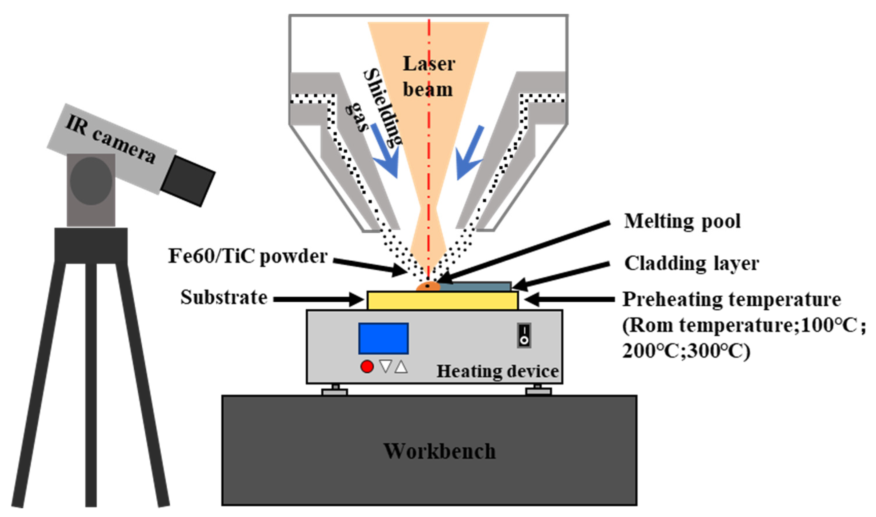
The experimental setup employed an XL-F2000T continuous fiber laser processing system (laser source model: MFSC 2000 W, manufacturer: Maxphotonics Co., Ltd., Shenzhen, China) with a maximum laser power of 2000 W, utilized for conducting laser cladding experiments on the surface of 65Mn steel. The schematic diagram illustrating the preparation of a single Fe/TiC composite coating layer is depicted in Figure 2. The laser beam, with a wavelength of 1080 ± 5 nm, produced spot diameters of 2.10 mm when interacting with the surface of the substrate. Before the laser cladding experiment, we use metallographic sandpaper (180–400 CW) to polish the substrate so that the scratches remain in one direction, clean the specimen with alcohol, and dry it for backup. To ensure the standardization of the experiment, we utilized the S1B-FF-110 × 100 flat sanding machine manufactured by Jiangsu Dongcheng Electrical and Mechanical Tools Co., Ltd. (Qidong, China) for substrate surface treatment. The substrate was preheated by utilizing a thermostatically controlled platform (model: DB-XAB; operating voltage: 220 V; maximum operating temperature: 400 °C; manufacturer: Shanghai, China). The temperature control range of the heater is RT-400, and the temperature control accuracy of the instrument is ±1 °C. Contact heating was employed to preheat the substrate. The lower surface of the substrate was in contact with the heating equipment to achieve temperature heating through heat conduction. The preheating temperature was categorized into four levels: room temperature, 100 °C, 200 °C, and 300 °C. In order to ensure the accuracy of the substrate heating temperature, we use the 225 s thermal imager produced by FOTRIC Smart Technology Co., Ltd. (Shanghai, China) to monitor the temperature of the entire preheating process. Once the predetermined temperature is reached, we wait for 10 min to ensure that the temperature tends to be stable. The temperature measurement range of the device is 0~350 °C, and the temperature measurement accuracy is ±2 °C or ±2%. The maximum value is taken when the ambient temperature is 10~35 °C. Based on these equipment and conditions, we conducted three sets of experiments to ensure the repeatability of the results. Therefore, the temperature heating method is accurate and reliable. Temperature contour diagrams, depicted in Figure 3, were generated upon reaching specific temperatures on the substrate, with Sp1 (10, 5, 2), Sp2 (10, 20, 2), and Sp3 (10, 35, 2) representing the coordinates of the temperature monitoring points. Argon serves as the protective gas during the laser cladding process, maintaining a gas flow rate of 10 L/min to prevent oxidation reactions between the cladding powder, substrate, and air. During the laser cladding process, the powder is transported to the surface of the substrate, and the substrate itself is not protected. The effect of airflow is to form a protective layer between the powder and the substrate to prevent the influence of oxygen.

2.3. Analysis and Characterization Methods

The Shimadzu 6100 X-ray diffractometer (XRD) (Kyoto, Japan) was used to analyze the phase composition of the cladding. The Sigma500 (Oberkochen, Germany) field emission scanning electron microscope was employed to examine the microstructure of the cladding, while an energy spectrometer (EDS) was utilized to detect the elemental content in various micro-regions of the cladding layer. A Vickers microhardness tester (Wilson VH1202, Fort Worth, TX, USA) with a load of 500 g and a loading time of 10 s is used for composite coating microhardness tests. The sample size used for the wear test is 10 mm × 10 mm × 2 mm. Before characterizing the wear resistance, we first removed one-third of the upper half of the single-layer multi-pass cladding layer and polished the surface to 5000 mesh to test the friction and wear performance in the middle of the cladding layer. The test was conducted at intervals of 0.15 mm from the top of the cladding layer to the substrate, and the average value was calculated from three measurements. The SFT-2M pin-disc type friction and wear tester was utilized, with Si3N4 selected as the friction vice. A loading force of 20 N, a rotational radius of 2 mm, and a fixed frequency of 1 Hz were employed, with a wear duration of 30 min. The friction coefficient of the cladding layer was obtained from the wear time curve, and the wear volume and wear rate of the cladding layer were calculated using measurements of the width of the abrasion marks. Subsequently, quantitative analysis and characterization were conducted. Electrochemical performance was assessed utilizing a typical three-electrode system employing a Chenhua 660E (Shanghai, China) electrochemical workstation. The reference electrode used was the saturated mercuric electrode, and the counter electrode utilized was a platinum electrode. The cladding layer served as the working electrode. Polarization curves were produced in a 3.5% NaCl solution at a temperature of 30 ± 2 °C to assess essential electrochemical parameters, such as the self-corrosion current density and self-corrosion potential of the cladding layer. The sample size for the corrosion test is 10 mm × 10 mm × 2 mm. Before the corrosion performance characterization, the surface of the sample was sanded and polished to achieve the mirror effect. All samples underwent polishing with a 2000 mesh level until the test surface had no visible scratches. Subsequently, the five non-test surfaces of the samples were sealed using epoxy resin. The test parameters included a scanning rate of 0.001 V/s, a corrosion area of 15 × 15 mm2, and a test duration of 1200 s. To ensure the precision of the electrochemical polarization test, each test sample was immersed in a NaCl solution until the open circuit potential (OCP) stabilized [27].

3. Results and Discussion

3.1. Phase Composition

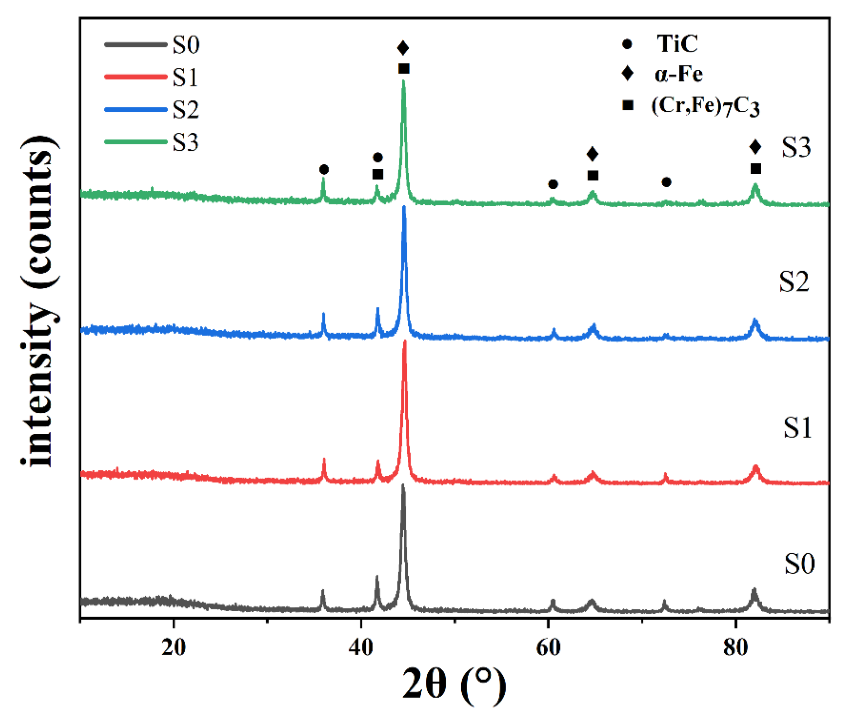
To assess the influence of different preheating temperatures on the phases of the coating, XRD tests were conducted on samples subjected to various preheating temperatures. The results are depicted in Figure 4. As illustrated, the composite coating exhibits several phases, including α-Fe, (Cr, Fe)M7C3, and TiC. It is noteworthy that while the diffraction peaks of the coating appear similar, the substrate preheating temperatures are different. Based on the Bragg law: 2dsinθ = nλ, (where d represents the interplanar spacing of the atomic lattice, θ is the angle between the reflection line and the reflection crystal plane, n is the reflection coefficient, and λ is the wavelength), the decrease in the peak angle associated with the α-Fe phase signifies an expansion of the lattice distance. It is important to highlight that in this investigation, the XRD spectra revealed the presence of corresponding diffraction peaks of the (Cr, Fe)7C3 phase. This phenomenon may be attributed to the following reasons: (1) The strong affinity between Cr and C atoms facilitates the formation of the (Cr, Fe)7C3 phase. (2) The similar atomic radius of Fe and Cr allows for easy substitution of Fe atoms for Cr atoms in chromium carbide, resulting in the formation of the (Cr, Fe)7C3 phase. This observation is consistent with the findings reported by Zhang et al. [28].

3.2. Microstructure

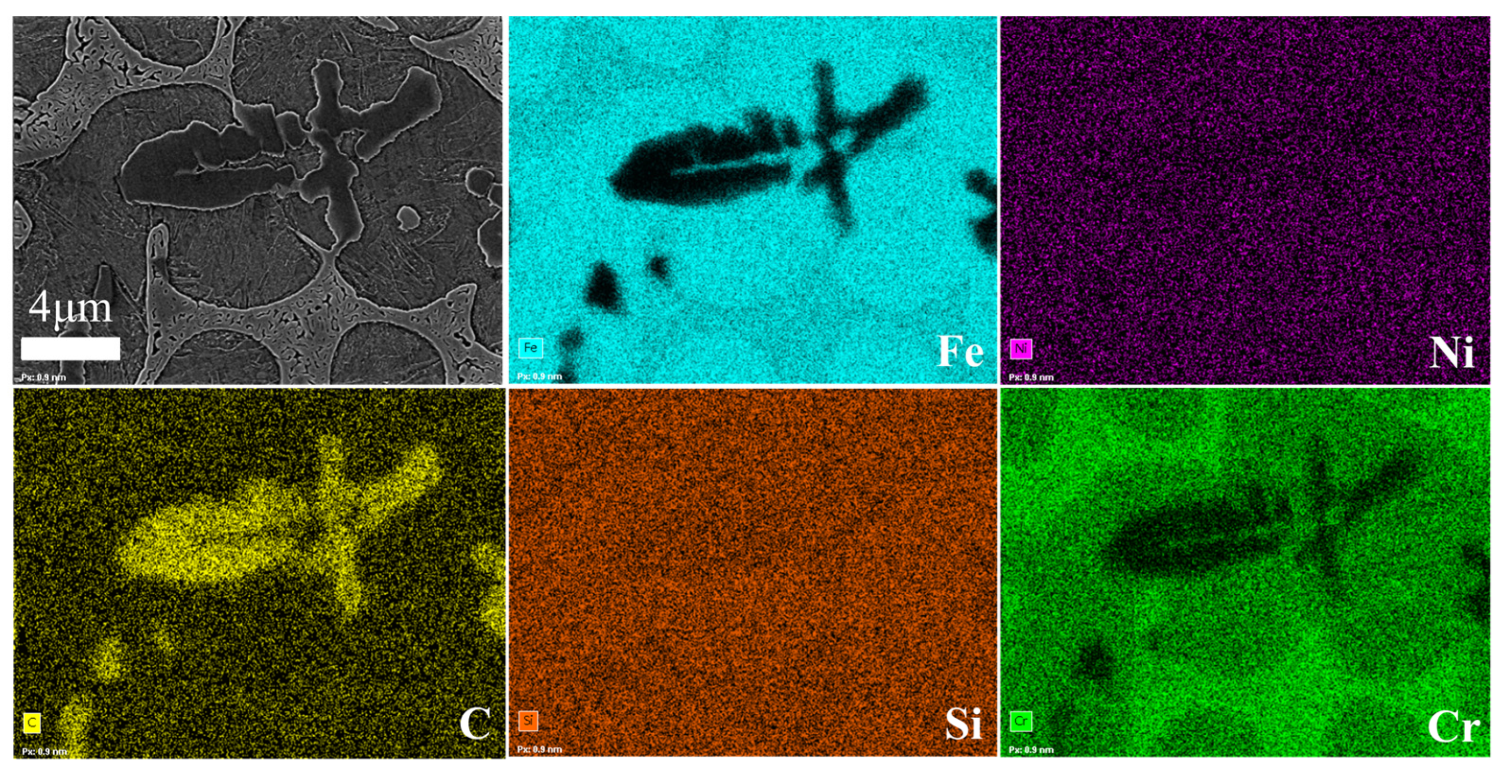
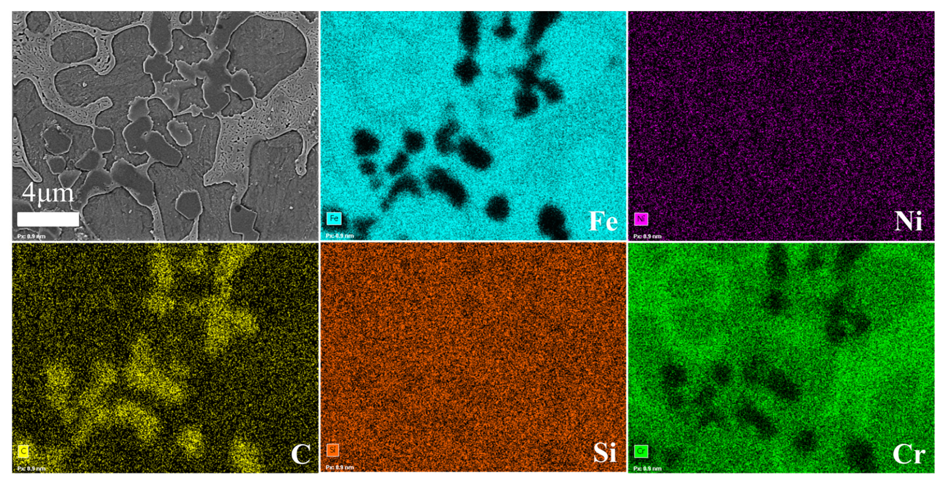
The microstructure of the cladding layer in various samples is illustrated in Figure 5. As observed from the figure, distinct dissolution lines are evident between the fusion cladding layer and the substrate, indicating the presence of a metallurgical bond between them. The composite coating exhibits heat-affected, bonded, and fusion cladding zones in a bottom-up sequence. Notably, the cross-section morphology of the composite coating is suboptimal at room temperature, characterized by significant gaps on the coating surface. However, preheating the substrate leads to noticeable improvements in the coating’s surface quality. According to Figure 5a–d, it can be seen that the distribution of TiC particles depends on the preheating temperature. The presence of convection in the molten pool during the preparation of Fe/TiC composite coating may lead to a shift in the distribution of TiC particles within the coating. Zhai et al. [17] discussed the genesis of convection in the molten pool during laser cladding. They attributed the convection to two main factors: (1) natural convection arose from density variations in the cladding material, and (2) Marangoni convection generated by the molten pool due to surface tension. The preheating temperature will make the Marangoni convection more intense. Furthermore, the cladding angle of the coating demonstrates a trend of initial increase followed by a subsequent decrease. It has been reported in reference [29] that a higher cladding angle value corresponds to a more extensive spread of cladding material on the substrate surface. As illustrated in Figure 5, numerous large-sized black particles are randomly dispersed throughout the coating. Figure 5(c1,d1) provides high-magnification views of these large-sized black particles within the coating. Single and petal-like particles are rich in Ti and C, and these TiC particles can be observed from the SEM images. These particles are produced by the dissolution/precipitation mechanism due to the decomposition of Ti and C atoms from the original TiC. Secondly, the powder we use is ceramic powder TiC particles, and the existing characterization methods can indicate that the black particles are TiC. Furthermore, the EDS mapping outcomes illustrated in Figure 6 and Figure 7 validate that these black particles are indeed TiC particles. The formation of TiC particles is attributed to the short duration of the laser cladding process, combined with rapid heating and cooling rates, rendering it challenging to fully melt the large-sized TiC particles [30]. Figure 5(a1–d1) depicts the binding area showcasing diverse cross-section morphologies of the specimens. At the bottom of the bonding area, various specimens exhibit a wedge-shaped structure. The wedge-shaped area of the room temperature composite coating is relatively small, whereas, with an increase in preheating temperature, there is a discernible tendency for the wedge-shaped area to expand. The presence of a wedge-shaped area facilitates extensive embedding of the coating into the substrate, indicating the formation of a robust metallurgical bond between the coating and the substrate, thereby ensuring a sufficiently strong bond interface. Notably, the direction of dendritic growth at the bottom of the coating is highly significant, with columnar crystals primarily growing perpendicular to the fusion line of the coating. This phenomenon arises due to slower heat dissipation near the substrate at the bottom of the melt pool, prompting particles at the bottom of the coating to grow upwards. Figure 5(a2–d2) displays the SEM morphology of the central area of the Fe/TiC composite coating, indicating that the solidification traits of the Fe/TiC cladding layer structure remain relatively unchanged.

3.3. Microhardness

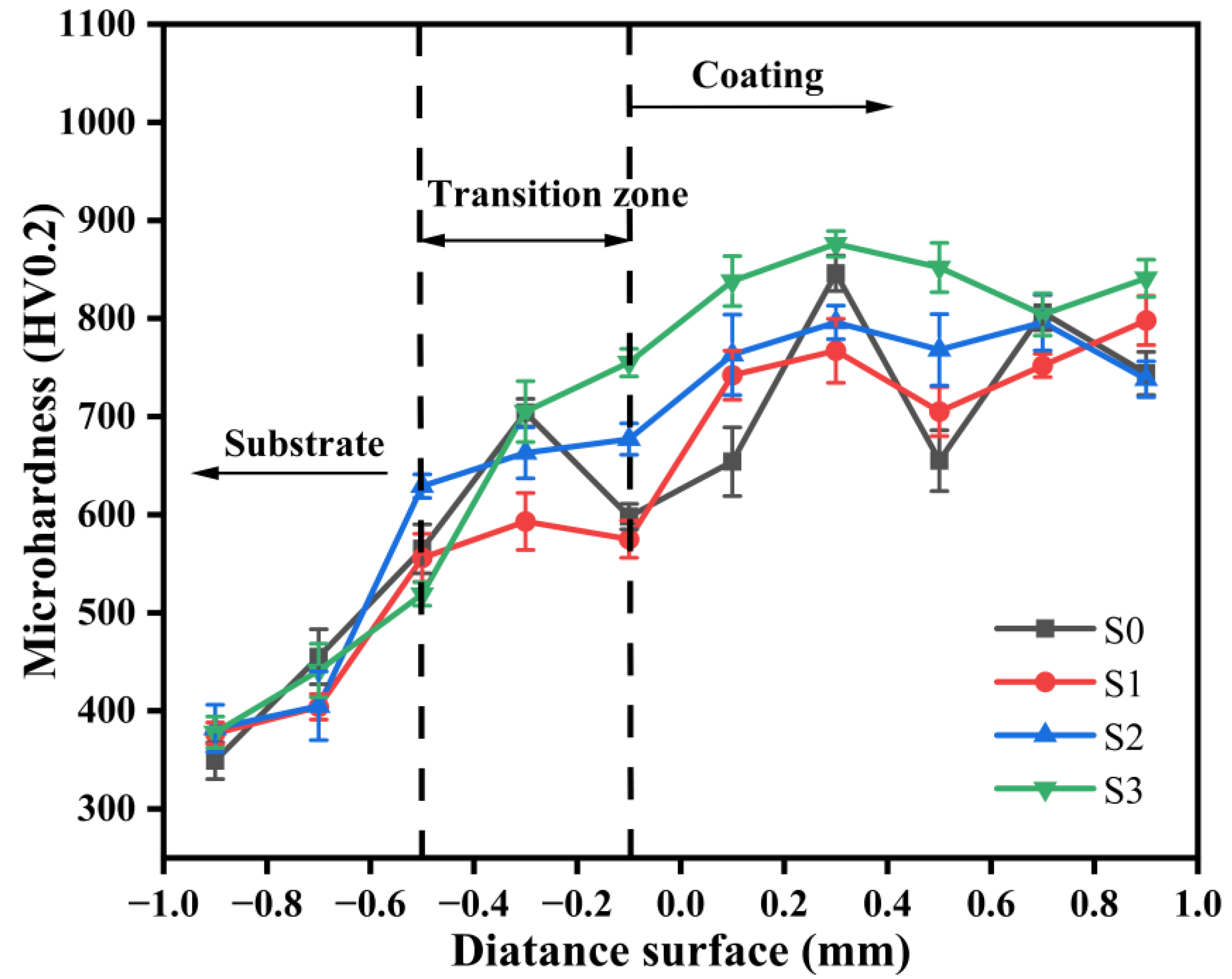
Figure 8 depicts the distribution of microhardness in the composite coating. Following calculation and analysis, the average hardness values for coating subjected to different preheating temperatures were determined as follows: 741 ± 50 HV (room temperature), 753 ± 50 HV (preheating temperature of 100 °C), 772 ± 50 HV (preheating temperature of 200 °C), and 842 ± 50 HV (preheating temperature of 300 °C). The hardness of the cladding layer predominantly fell within the range of 700 to 900 HV. Notably, at room temperature, the hardness of the cladding layer exhibited considerable fluctuation, possibly attributable to insufficient time for the complete diffusion of elements within the molten pool. Of particular interest, specimen S3 exhibited the highest average hardness, approximately 2.45 times that of the base 65Mn steel.
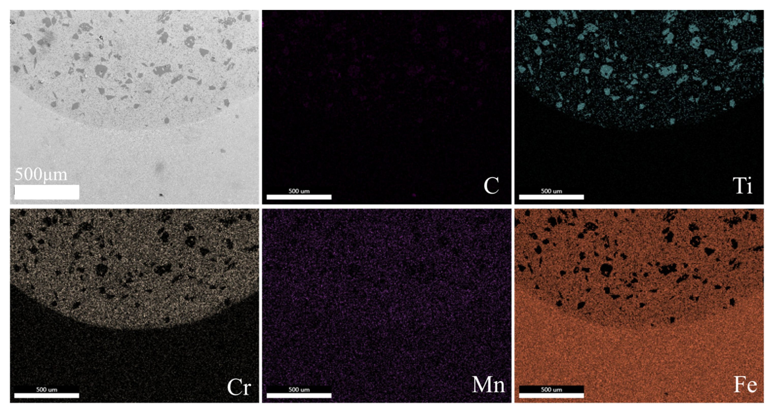
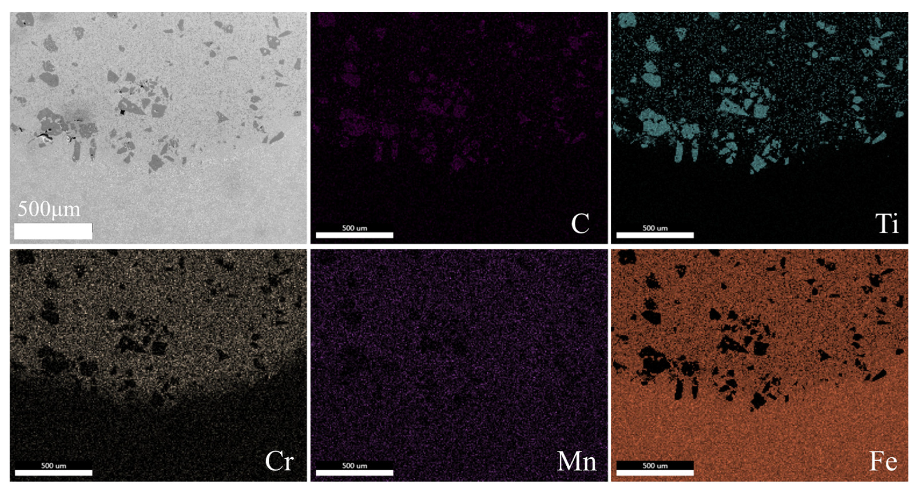
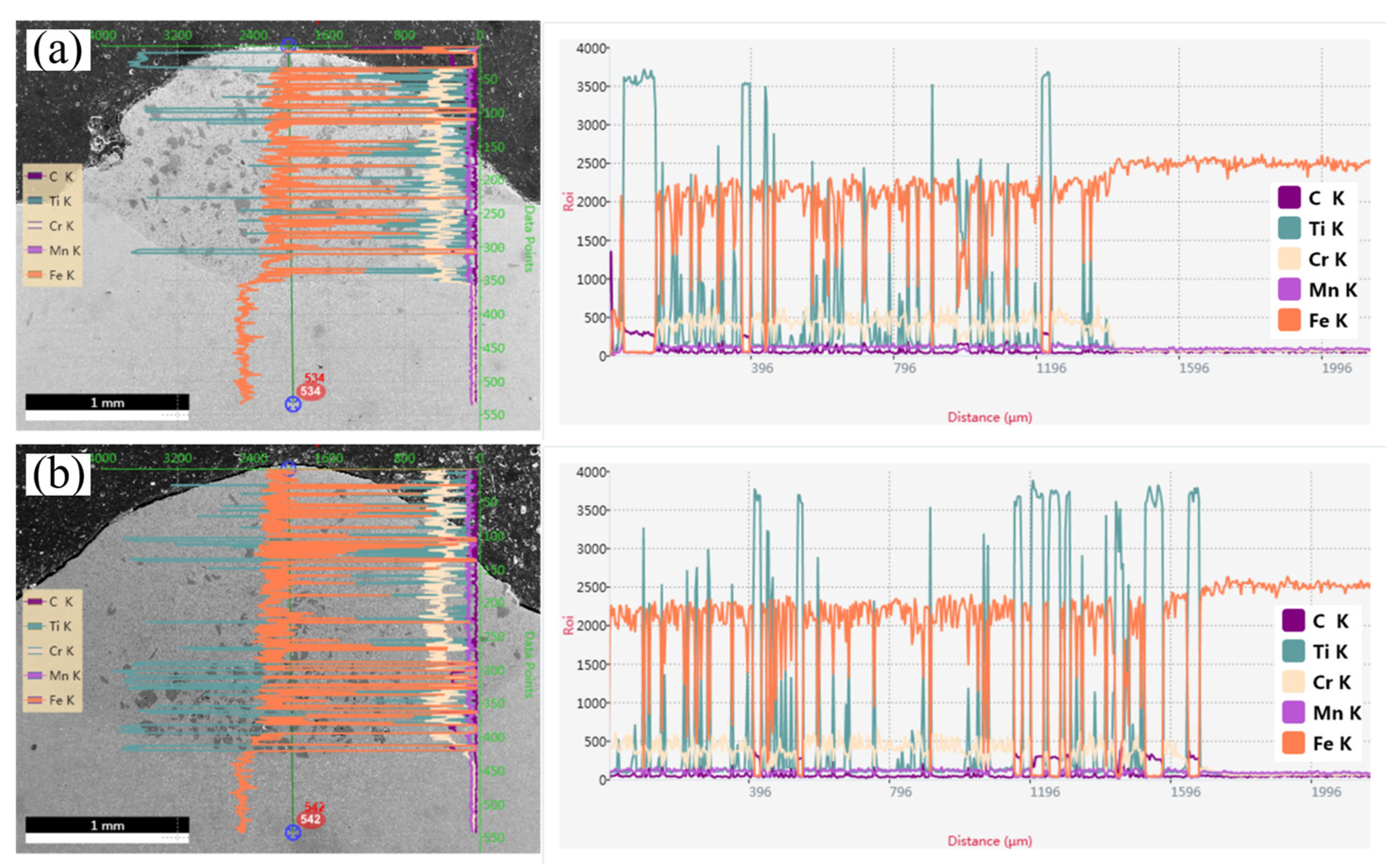
Figure 9 and Figure 10 depict the elemental distribution within the bonding zone of Fe/TiC composite coating for specimens S0 and S3. It is evident that both S0 and S3 specimens exhibit enrichment of Ti, Cr, Mn, and Fe elements within their bonding zones, alongside minor quantities of carbon (C) elements. Notably, when the substrate is preheated to 300 °C, enhanced diffusion of C and Mn elements into the Fe/TiC composite coating is observed, resulting in a homogeneous distribution of C and Mn within the Fe/TiC composite coating of the S3 specimen preheated at 300 °C, as illustrated in Figure 10. This phenomenon aligns with findings reported by Wang et al. [23], who proposed that substrate preheating facilitates the sufficient diffusion of elements within the molten pool. To further verify this conclusion, EDS line scans were conducted on the S0 specimen at room temperature and the S3 specimen with the substrate preheated to 300 °C. This analysis aimed to investigate the interfacial element distribution and metallurgical bonding between the coating and substrates of each specimen, as illustrated in Figure 11. It is evident that the interface between the composite coating and the substrate is clearly discernible in both the S0 and S3 specimens, with the Fe/TiC composite coating exhibiting the highest concentrations of Fe and Ti elements. Additionally, in the S0 specimen, Ti element distribution appears non-uniform, potentially accounting for the significant microhardness fluctuations observed. Furthermore, as the scan progressed, molten iron from the substrate surface infiltrated the coating, leading to a gradual increase in iron content from the fusion-coated layer to the substrate. This phenomenon indicates mutual diffusion between the coating and substrate, affirming the establishment of a metallurgical bond between them.

3.4. Wear Resistance

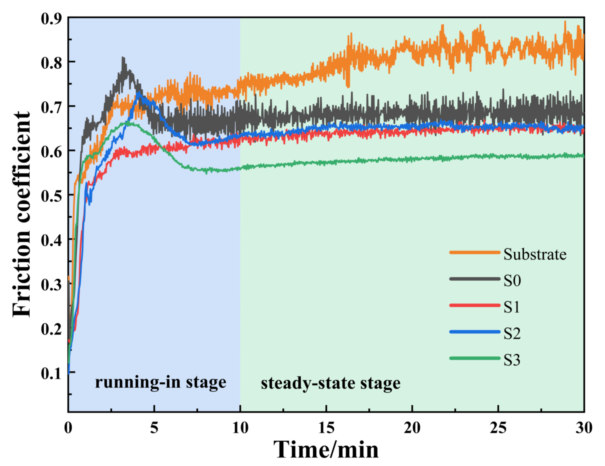
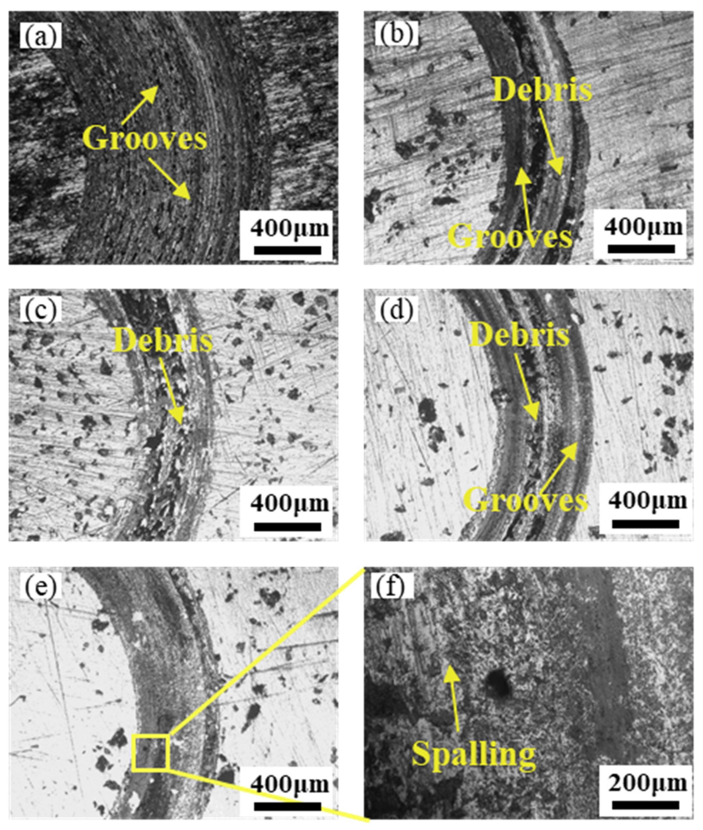
To examine the impact of different preheating temperatures of the substrate on the wear resistance of the composite coating, a series of friction and wear performance tests were performed on different samples. Figure 12 illustrates the evolution of the friction coefficient over time between Fe/TiC composite coating and 65Mn steel substrate under dry sliding conditions at different preheating temperatures, conducted at room temperature. The experimental findings reveal that initially, all specimens underwent a run-in stage in the friction and wear test, characterized by a rapid increase in friction coefficient accompanied by significant fluctuations. This behavior tended to stabilize with prolonged friction test duration. Hence, the friction coefficient for each specimen within the 10–30 min duration was utilized to calculate the average friction coefficient. This specific period is attributed to the steady-state regime. Initially, at a substrate preheating temperature of 300 °C, the average coefficient of friction for the coating was approximately 0.58, with a corresponding wear volume of about 0.0018 mm3, representing the lowest values observed and thus demonstrating the outstanding wear resistance of the S3 specimen. This enhancement notably augments the homogeneity of elemental composition within the composite coating, thereby promoting a relatively stable average friction coefficient. Furthermore, a comparative analysis of the average coefficient of friction and wear characteristics among the substrate (S0 specimen) and the composite coating with and without substrate preheating (S3 specimen) was conducted, as illustrated in Figure 13. The results suggest that the S3 specimen has an average friction coefficient that is 0.85 times lower than that of the S0 specimen and 0.72 times lower than that of the substrate. Additionally, the wear volume of the S3 specimen is 0.45 times lower than that of the S0 specimen and 0.32 times lower than that of the substrate. Thus, the preheating temperature of the substrate has a notable impact on the wear properties of the composite coating. Additionally, Figure 14 presents the wear morphologies of the Fe/TiC composite coating from different specimens. Observations reveal that the wear track width is most pronounced on the substrate, as depicted in Figure 14a, suggesting the substrate undergoes the most severe abrasion. This can be attributed to the softer nature of the 65Mn substrate compared with the friction-imposing Si3N4 steel ball, which exhibits the widest wear mark width under identical frictional conditions. Furthermore, examination of Figure 14b,c reveals the presence of grooves and flaking pits on the wear surfaces of the S0 and S1 specimens, indicating a combination of abrasive and adhesive wear mechanisms. Subsequent analysis of Figs. 14d–f illustrates the wear characteristics of the S2 and S3 specimens. Notably, when the substrate preheating temperatures were set at 200 °C and 300 °C, the abraded Fe/TiC composite coating displayed relatively smooth surfaces with only minor grooves and isolated pits, suggestive of light wear primarily attributable to slight abrasive action. Consequently, the judicious preheating of the substrate contributes to the enhanced wear resistance of the composite coating, primarily ascribed to the self-lubricating effect of preheating [25].

3.5. Electrochemical Corrosion

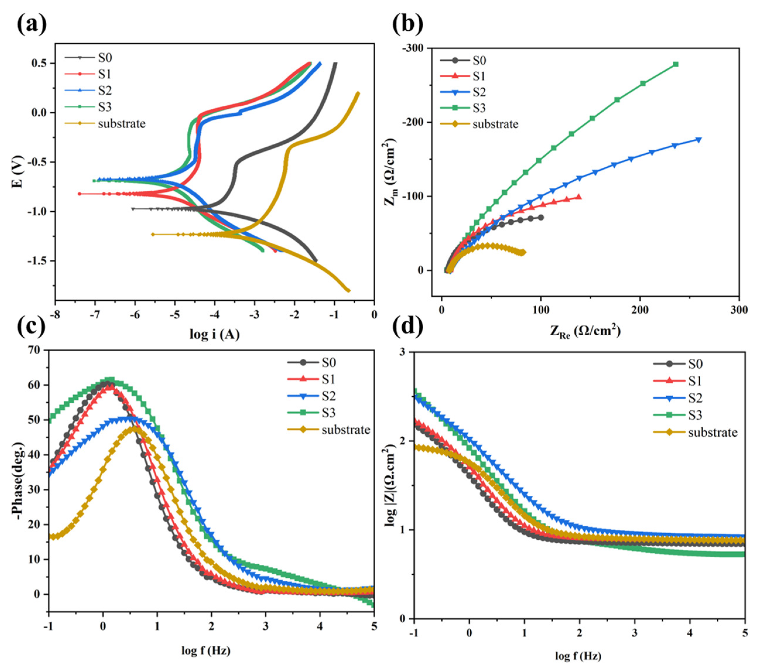
Figure 15 presents the findings from electrochemical experiments. Specifically, Figure 15a illustrates the kinetic potential polarization curves, with the corresponding electrochemical parameters detailed in Table 3. Within Table 3, Ecorr represents the self-corrosion potential, a fundamental thermodynamic parameter indicative of the material’s susceptibility to corrosion reactions [31]. The higher the self-corrosion potential, the greater the resistance of the metal to electron loss, and the corrosion reaction rate is not necessarily correlated. Conversely, Icorr denotes the self-corrosion current density, which shows a direct relationship with the corrosion rate [32]. Figure 15a depicts the anodic polarization curves, indicating that all coating exhibits passivation regions, suggesting passivation behavior in the corrosion process. This phenomenon is primarily attributed to the formation of a dense passivation film on the surface of the laser cladding layer due to the presence of Cr elements. Additionally, the enrichment of Ni elements within the laser cladding layer plays a crucial role in preventing the reduction of oxidants at the location of the passivation film, consequently leading to a notable enhancement in the corrosion resistance of the coating [33]. It is deduced that the corrosion rate diminishes as the substrate preheating temperature increases, reaching its nadir at 300 °C, correlating with the electrochemical parameters presented in Table 3. The notable enhancement in corrosion resistance can be attributed to two primary factors: (1) The formation of a compact passivation film on the surface of the composite coating during electrochemical corrosion, thereby mitigating the corrosion rate [27,34]. (2) Enhanced elemental diffusion within the composite coating subsequent to substrate preheating, consequently bolstering the corrosion resistance of the composite coating [35].
Analyzing the Nyquist plot depicted in Figure 15b, it is evident that the radius of the capacitive impedance loop for the matrix preheated coating surpasses that of the room temperature coating. Furthermore, the radius of the capacitive impedance loop for the composite coating demonstrates a progressive augmentation with increasing preheating temperatures. It is widely acknowledged that a larger radius of the capacitive impedance loop correlates with superior corrosion resistance. Moreover, the Nyquist plot in Figure 15b reveals that the radius of the capacitive impedance loop for the substrate preheated coating exceeds that of the composite coating at room temperature. Similarly, the radius of the capacitive impedance loop for the composite coating exhibits an upward trend with escalating preheating temperatures. As it is commonly understood, a larger radius of the capacitive impedance loop indicates better corrosion resistance [32]. Therefore, substrate preheating can greatly improve the corrosion resistance of the composite coating. Typically, the ability to inhibit electrolyte penetration in the composite coating is associated with the mid-frequency loop [36]. The larger the mid-frequency loop, the greater the corrosion resistance. Upon preheating the substrate at 200 °C and 300 °C, the mid-frequency loops depicted in the Bode plots of Figure 15c exhibited considerable enlargement compared to other curves, denoting superior corrosion resistance in the respective composite coating. Additionally, as illustrated in Figure 15d, the |Z|0.01 Hz values exhibited a gradual increase with escalating substrate preheating temperatures, indicating enhanced efficacy of the composite coating as barrier layers against corrosion with increasing preheating temperatures.

4. Conclusions

In this study, laser surface modification of 65Mn steel was conducted through the integration of substrate preheating with laser cladding technology. The influence of varying substrate preheating temperatures on the microstructure, phase distribution, elemental composition, microhardness, wear resistance, and corrosion resistance of Fe/TiC composite coating was systematically investigated. The main conclusions are drawn as follows.
(1)
The cladding angle of the Fe/TiC composite coating initially increases and then decreases as the substrate preheating temperature rises. Specifically, the cladding angle increases from 130° to 148° and then decreases to 140°.
(2)
The implementation of substrate preheating enhanced both the microhardness and wear resistance of the composite coating. Specifically, the microhardness of specimens subjected to substrate preheating exhibited an increase ranging from 50 to 100 HV compared with specimens processed at room temperature. The hardness and wear resistance properties of the coating are optimal at a substrate preheating temperature of 300 °C.
(3)
The preheating temperature enhances the microstructure and compositional uniformity of the cladding layer by increasing the heat capacity of the substrate, thereby improving the wear and corrosion resistance of the cladding layer.

Author Contributions

Conceptualization, W.S., C.C. and F.A.; project administration, W.S.; formal analysis, B.Z., K.L., Z.X., Y.X. and K.H.; validation, B.Z., K.L., Z.X., Y.X. and K.H.; investigation, C.C., B.Z., Y.X. and F.A.; writing—original draft preparation, C.C., F.A. and W.S. All authors have read and agreed to the published version of the manuscript.

Funding

The National Natural Science Foundation of China (62073089); the Special Projects in Key Fields of Guangdong Colleges and Universities (2020ZDZX2061); the Postgraduate Education Innovation Project of Guangdong Ocean University (040502752328); the Special Funds for the Cultivation of Guangdong College Students’ Scientific and Technological Innovation. (“Climbing Program” Special Funds) (pdjh2023a0242).

Data Availability Statement

Data are contained within the article.

Conflicts of Interest

The authors declare no conflicts of interest.

References

  1. Lu, Z.G.; Du, C.Y.; Chen, Q.C.; Niu, T.Y.; Wang, N.; Song, W.L. Wear and Friction Characteristics of 65mn Steel for Spike-Tooth Harrow. Coatings 2021, 11, 319. [Google Scholar] [CrossRef]
  2. Chen, K.Y.; Yang, X.F.; Li, W.Y.; Xia, G.F.; Wang, S.R.; Wang, K. Study on the Wear and Corrosion Resistance of Fe–Mo Coatings on 65mn Steel Ploughshares by Laser Cladding. Appl. Phys. A 2022, 128, 795. [Google Scholar] [CrossRef]
  3. Xin, W.; Feng, S.K.; Zhang, W.G. Microstructure, Phase Composition and Wear Properties of Iron-Based Gradient Coatings by Laser Cladding on 65mn Steel. Surf. Coat. Technol. 2024, 477, 130290. [Google Scholar]
  4. Li, J.W.; Tong, J.; Hu, B.; Ma, Y.H. Biomimetic Functional Surface of Reducing Soil Adhesion on 65mn Steel. Adv. Mech. Eng. 2019, 11, 1687814019889801. [Google Scholar] [CrossRef]
  5. Sun, B.; Wang, Q.Q.; Chen, Y.X.; Cheng, J.B.; Zhao, H.C.; Zhu, S.S.; Zhang, B.S.; Liang, X.B.; Shen, B.L. Dendrite Refinement and Wear Performance Enhancement in Laser-Cladded Fe-Based Coatings after Multi-Step Laser Remelting. Surf. Coat. Technol. 2022, 447, 128794. [Google Scholar] [CrossRef]
  6. Daram, P.; Banjongprasert, C. The Influence of Post Treatments on the Microstructure and Corrosion Behavior of Thermally Sprayed Nicrmoal Alloy Coating. Surf. Coat. Technol. 2020, 384, 125166. [Google Scholar] [CrossRef]
  7. Ryabchikov, A.I.; Kashkarov, E.B.; Shevelev, A.E.; Syrtanov, M.S. High-Intensity Chromium Ion Implantation into Zr-1nb Alloy. Surf. Coat. Technol. 2020, 383, 125272. [Google Scholar] [CrossRef]
  8. Vernardou, D. Special Issue: Advances in Chemical Vapor Deposition. Materials 2020, 13, 4167. [Google Scholar] [CrossRef] [PubMed]
  9. Zhang, Q.; Han, B.; Li, M.Y.; Chen, Z.B.; Hu, C.Y.; Jia, C.X. Comparison of Cocrfeni Coatings Prepared Via High-Speed Laser Cladding and Normal Laser Cladding on Microstructure and Properties. Intermetallics 2023, 153, 107795. [Google Scholar] [CrossRef]
  10. Zhang, Z.; Yu, T.; Kovacevic, R. Erosion and Corrosion Resistance of Laser Cladded Aisi 420 Stainless Steel Reinforced with Vc. Appl. Surf. Sci. 2017, 410, 225–240. [Google Scholar] [CrossRef]
  11. Zhou, S.F.; Xu, Y.B.; Liao, B.Q.; Sun, Y.J.; Dai, X.Q.; Yang, J.X.; Li, Z.Y. Effect of Laser Remelting on Microstructure and Properties of Wc Reinforced Fe-Based Amorphous Composite Coatings by Laser Cladding. Opt. Laser Technol. 2018, 103, 8–16. [Google Scholar] [CrossRef]
  12. Liang, H.; Liu, J.H.; Sun, L.K.; Hou, J.X.; Cao, Z.Q. Optimization of the Forming Quality of a Laser-Cladded Alcrfeniw0.2 High-Entropy Alloy Coating. Coatings 2023, 13, 1744. [Google Scholar] [CrossRef]
  13. Singh, A.K.; Simant, K.; Dey, D.P.; Das, A.K.; Pal, A.R.; Pratihar, D.K.; Roy, A.C. Experimental Investigation and Parametric Optimization for Minimization of Dilution During Direct Laser Metal Deposition of Tungsten Carbide and Cobalt Powder Mixture on Ss304 Substrate. Powder Technol. 2021, 390, 339–353. [Google Scholar] [CrossRef]
  14. Sun, Y.W.; Hao, M.Z. Statistical Analysis and Optimization of Process Parameters in Ti6al4v Laser Cladding Using Nd:Yag Laser. Opt. Lasers Eng. 2012, 50, 985–995. [Google Scholar] [CrossRef]
  15. Mohsan, A.U.H.; Zhang, M.; Wang, D.F.; Zhao, S.; Wang, Y.S.; Chen, C.Y.; Zhang, J.H. State-of-the-Art Review on the Ultrasonic Vibration Assisted Laser Cladding (Uvalc). J. Manuf. Process. 2023, 107, 422–446. [Google Scholar] [CrossRef]
  16. Wang, Y.Y.; Shi, H.; Hao, X.H.; Liu, H.X.; Zhang, X.W. Microstructure and Wear Resistance of Fe60 Laser Cladding Coating Assisted by Steady Magnetic Field–Mechanical Vibration Coupling Field. Coatings 2022, 12, 751. [Google Scholar] [CrossRef]
  17. Zhai, L.L.; Ban, C.Y.; Zhang, J.W. Investigation on Laser Cladding Ni-Base Coating Assisted by Electromagnetic Field. Opt. Laser Technol. 2019, 114, 81–88. [Google Scholar] [CrossRef]
  18. Li, X.; Peng, J.H.; Wang, F.; Liu, Z.Z.; Feng, X.Y. Effect of Electrically Assisted Preheating on Microstructure and Properties of Laser-Cladded Co-Based Coating on Cp-Ti Alloy Substrate. Coatings 2023, 13, 1379. [Google Scholar] [CrossRef]
  19. Wang, J.Y.; Cui, X.F.; Zhao, Y.; Zhang, Y.; Fan, X.T.; Zha, M.R.; Jin, G. Microstructure and Performance Enhancement of the Tin/Fe-Based Cladding Layer Induced by Mechanical Vibration Assisted Underwater Wet Laser Cladding. Surf. Coat. Technol. 2024, 476, 130176. [Google Scholar] [CrossRef]
  20. Zhang, G.T.; Liu, W.J.; Bian, H.Y.; Xing, F.; Xu, X.W. Effect of Substrate Preheating on Cracking and Wear Resistance of Laser-Cladded Tribaloy T-800 Coatings on Dd5 Single-Crystal Alloy. J. Therm. Spray Technol. 2024, 33, 1027–1039. [Google Scholar]
  21. Hebbale, A.M.; Manish, T.; Ravi, B. Microstructural Studies of Composite (Cr3C2–Nicr) Laser Clads Developed on Preheated Substrate T91. Trans. Indian Inst. Met. 2021, 74, 593–600. [Google Scholar] [CrossRef]
  22. Farahmand, P.; Liu, S.; Zhang, Z.; Kovacevic, R. Laser Cladding Assisted by Induction Heating of Ni–Wc Composite Enhanced by Nano-Wc and La2O3. Ceram. Int. 2014, 40 Pt A, 15421–15438. [Google Scholar] [CrossRef]
  23. Wang, H.Z.; Cheng, Y.H.; Yang, J.Y.; Liang, X.B. Microstructure and Properties of Fe Based Amorphous Coatings Deposited by Laser Cladding under Different Preheating Temperatures. J. Non-Cryst. Solids 2023, 602, 122081. [Google Scholar] [CrossRef]
  24. Bidron, G.; Doghri, A.; Malot, T.; Fournier-dit-Chabert, F.; Thomas, M.; Peyre, P. Reduction of the Hot Cracking Sensitivity of Cm-247lc Superalloy Processed by Laser Cladding Using Induction Preheating. J. Mater. Process. Technol. 2020, 277, 116461. [Google Scholar] [CrossRef]
  25. Wu, T.; Shi, W.Q.; Xie, L.Y.; Gong, M.M.; Huang, J.; Xie, Y.P.; He, K.F. Effect of Preheating Temperature on Geometry and Mechanical Properties of Laser Cladding-Based Stellite 6/Wc Coating. Materials 2022, 15, 3952. [Google Scholar] [CrossRef] [PubMed]
  26. Soffel, F.; Papis, K.; Bambach, M.; Wegener, K. Laser Preheating for Hot Crack Reduction in Direct Metal Deposition of Inconel 738lc. Metals 2022, 12, 614. [Google Scholar] [CrossRef]
  27. Wang, H.Z.; Cheng, Y.H.; Song, W.; Yang, J.Y.; Liang, X.B. Research on the Influence of Laser Scanning Speed on Fe-Based Amorphous Coating Organization and Performance. Intermetallics 2021, 136, 107266. [Google Scholar] [CrossRef]
  28. Zhang, C.H.; Zhang, H.; Wu, C.L.; Zhang, S.; Sun, Z.L.; Dong, S.Y. Multi-Layer Functional Graded Stainless Steel Fabricated by Laser Melting Deposition. Vacuum 2017, 141, 181–187. [Google Scholar] [CrossRef]
  29. Khorram, A.; Jamaloei, A.D.; Paidar, M.; Cao, X.J. Laser Cladding of Inconel 718 with 75Cr3C2+25(80Ni20Cr) Powder: Statistical Modeling and Optimization. Surf. Coat. Technol. 2019, 378, 124933. [Google Scholar] [CrossRef]
  30. Zhang, H.F.; Wang, L.; Zhang, S.; Wu, C.L.; Zhang, C.H.; Sun, X.Y.; Chen, J. An Investigation on Wear and Cavitation Erosion-Corrosion Characteristics of the Tic Modified Fe-Based Composite Coating Via Laser Cladding. J. Mater. Res. Technol. 2023, 26, 8440–8455. [Google Scholar] [CrossRef]
  31. Zhao, W.; Kong, D.J. Effects of Laser Power on Immersion Corrosion and Electrochemical Corrosion Performances of Laser Thermal Sprayed Amorphous Alfesi Coatings. Appl. Surf. Sci. 2019, 481, 161–173. [Google Scholar] [CrossRef]
  32. Lu, J.Z.; Han, B.; Cui, C.Y.; Li, C.J.; Luo, K.Y. Electrochemical and Pitting Corrosion Resistance of Aisi 4145 Steel Subjected to Massive Laser Shock Peening Treatment with Different Coverage Layers. Opt. Laser Technol. 2017, 88, 250–262. [Google Scholar] [CrossRef]
  33. Zhu, Q.; Liu, Y.; Zhang, C.Y. Laser Cladding of Cocrfeni High-Entropy Alloy Coatings: Compositional Homogeneity Towards Improved Corrosion Resistance. Mater. Lett. 2022, 318, 132133. [Google Scholar] [CrossRef]
  34. Chen, J.L.; Zhou, Y.J.; Shi, C.; Mao, D.H. Microscopic Analysis and Electrochemical Behavior of Fe-Based Coating Produced by Laser Cladding. Metals 2017, 7, 435. [Google Scholar] [CrossRef]
  35. Chu, Z.H.; Deng, W.X.; Zheng, X.W.; Zhou, Y.Y.; Zhang, C.Y.; Xu, J.X.; Li, G. Corrosion Mechanism of Plasma-Sprayed Fe-Based Amorphous Coatings with High Corrosion Resistance. J. Therm. Spray Technol. 2020, 29, 1111–1118. [Google Scholar] [CrossRef]
  36. Dai, N.W.; Zhang, L.C.; Zhang, J.X.; Zhang, X.; Ni, Q.Z.; Chen, Y.; Wu, M.L.; Yang, C. Distinction in Corrosion Resistance of Selective Laser Melted Ti-6Al-4V Alloy on Different Planes. Corros. Sci. 2016, 111, 703–710. [Google Scholar] [CrossRef]
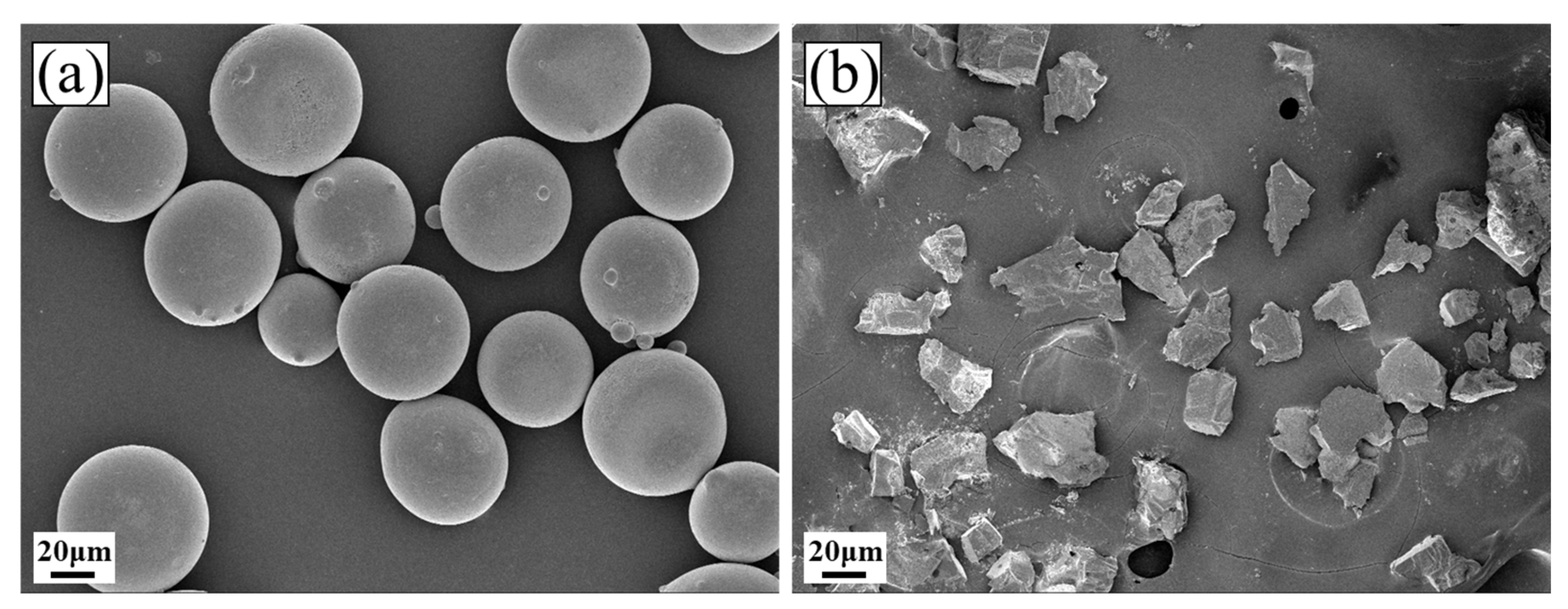
Figure 1. SEM morphology of the cladding material: (a) Fe60 powder; (b) TiC powder.
Lubricants 12 00216 g001
Figure 2. Schematic diagram of LC process.
Lubricants 12 00216 g002
Figure 3. Temperature contour diagrams when the substrate was preheated to a predetermined temperature: (a) 100 °C; (b) 200 °C; (c) 300 °C; (d) temperature monitoring points.
Lubricants 12 00216 g003
Figure 4. XRD patterns of the Fe/TiC composite coating of different specimens.
Lubricants 12 00216 g004
Figure 5. SEM morphologies of different specimens: (ad). Cross-sectional morphologies of S0–S3 (a1d1). Bonding area of S0–S3 (a2d2). Middle area of S0–S3.
Lubricants 12 00216 g005
Figure 6. EDS mapping results in the middle of the S0 specimen.
Lubricants 12 00216 g006
Figure 7. EDS mapping results in the middle of the S3 specimen.
Lubricants 12 00216 g007
Figure 8. Microhardness distribution of composite coating.
Lubricants 12 00216 g008
Figure 9. EDS mapping results in the bonding area of the S0 specimen.
Lubricants 12 00216 g009
Figure 10. EDS mapping results in the bonding area of the S2 specimen.
Lubricants 12 00216 g010
Figure 11. Line EDS results in different specimens: (a) S0; (b) S3.
Lubricants 12 00216 g011
Figure 12. Friction coefficient curves of the substrate and the different specimens.
Lubricants 12 00216 g012
Figure 13. Wear volumes and average friction coefficients of the different specimens.
Lubricants 12 00216 g013
Figure 14. SEM wear morphologies of the different specimens: (a) substrate; (b) S0; (c) S1; (d) S2; (e) S3; (f) magnification of S3.
Lubricants 12 00216 g014
Figure 15. The curves of electrochemical tests. (a) Anodic polarization curves; (b) Nyquist plots; (c,d) Bode plots.
Lubricants 12 00216 g015
Table 1. Chemical composition (wt%) of 65Mn steel substrate material.
MaterialsCMnPSSiNFe
65Mn0.620.90.0150.0030.230.0013Balance
Table 2. Chemical composition (wt%) of Fe60 cladding material.
TypeCSiBCrNiMnFe
Fe601.01.54.017/0.4Bal
Table 3. Electrochemical parameters obtained from polarization curves of the different specimens.
Preheating TemperatureIcorr/(μA·cm−2)Ecorr/(V)
Substrate2.05 × 10−4−1.216
Room temperature7.45 × 10−5−0.981
100 °C3.56 × 10−6−0.827
200 °C3.36 × 10−6−0.682
300 °C1.53 × 10−6−0.696
Disclaimer/Publisher’s Note: The statements, opinions and data contained in all publications are solely those of the individual author(s) and contributor(s) and not of MDPI and/or the editor(s). MDPI and/or the editor(s) disclaim responsibility for any injury to people or property resulting from any ideas, methods, instructions or products referred to in the content.