Article

Effects of Drilling Parameters and Mud Types on Wear Factors and Mechanisms of SM2535 Casings

1
Department of Mechanical Engineering, King Fahd University of Petroleum and Minerals, Dhahran 31261, Saudi Arabia
2
Interdisciplinary Research Center for Advanced Materials, King Fahd University of Petroleum and Minerals, Dhahran 31261, Saudi Arabia
3
Drilling Technology Team, EXPEC Advanced Research Center, Saudi Aramco, Dhahran 31261, Saudi Arabia
*
Author to whom correspondence should be addressed.
Lubricants 2023, 11(10), 420; https://doi.org/10.3390/lubricants11100420
Submission received: 13 August 2023 / Revised: 10 September 2023 / Accepted: 18 September 2023 / Published: 30 September 2023
(This article belongs to the Special Issue Wear and Corrosion Behaviour of Metals and Alloys)

Abstract

:
This work aims to explore the impact of side loads, drill-pipe tool-joint (DP-TJ) speed (rpm), and mud type on the austenitic stainless steel SM2535-110 casing wear characteristics. Actual field drill pipe tool joints, casings, and drilling muds are used in this study. The results of the study show that under both types of lubrication, the wear volume increased with radial load and DP-TJ speed. SM2535-110 casing specimens tested under oil-based mud (OBM) lubrication had higher casing wear volumes than those obtained under water-based mud (WBM) lubrication. This unexpected behavior is mainly due to the increase in the surface hardness of the casing specimens tested under WBM. The results also show that the specific wear rate or wear factor (K) (which is defined as the volume loss per unit load per unit distance sliding) values of specimens tested under WBM are in general two to four times higher than those obtained under OBM. While K values under WBM increase with both the side load and rpm, those under OBM show a sharp decrease with rpm. This behavior under OBM is due to this lubricant’s higher viscosity and the change of lubrication regime from thin film to thick film lubrication at higher rpm. Scanning electron microscopy (SEM) and the digital microscopic imaging (DMI) of SM235-110 casing specimens show that an aggressive combination of adhesive, abrasive, and plastic deformation was observed under WBM, while the dominant wear mechanism under OBM is abrasive wear.

1. Introduction

Casing wear is the process of a casing’s wall gradually losing thickness because of the drill string and casing’s relative motion [1]. Conditions such as the downhole forces, the total period the drill string has been in contact with the casing, the drill string speed, and the materials employed all affect how much casing wear occurs. This process is intricate and incorporates unpredictable abrasive, adhesive, and corrosive wear processes [2]. The main drilling characteristics that significantly impact casing wear at a given casing grade include rotary speed, rate of penetration (ROP), mud density, mud type, and bottom hole assembly [3].
Different grades of steel have been used for casing and the selection of the material is influenced by the operating conditions and drilling environment. From well testing through completion, high-pressure high-temperature wells present several obstacles to material design.
The amount of casing wear of several steel grades has been investigated in several studies, but its accurate estimate has proven to be quite difficult. This is because casing wear is a complicated process that depends on several parameters, including mud type, percentage of abrasives in the mud, tool joint hard-facing, tool joint diameter, drill string speed, contact pressure, and more [3,4,5,6,7,8].
Several experimental and numerical studies were performed to develop relationships between drilling parameters and casing wear factors and wear mechanisms. Zhang et al. [7] performed an experimental investigation of several casing steel grades to understand the effect of different drilling parameters on their wear behavior. They showed that the amount of wear increased with both side load and rpm. Moreover, they found that casing weight loss is inversely proportional to the casing steel grade. Huimei and Yishan [3] conducted a study to determine the effects of drilling factors on the casing wear and concluded that drill pipe spinning speed and drill pipe penetration rate are the most important factors in ultra-deep wells. Doering et al. [9] demonstrated that the new small-scale casing wear tester can produce wear mechanisms equivalent to both historical data produced by the DEA-42 test and from commercial down-hole service. Yu et al. [10] developed an equation that relates the maximum wear depth to the residual casing strength after accumulative wear. Chen et al. [11] examined the impact of drill string length, speed of rotation, direction of travel, and density of the drilling fluid on friction and they established a mathematical model to calculate the spacing of the friction reduction tool. Yu et al. [12] offered a theoretical and technological framework for the evaluation of casing integrity and casing configuration in directional wells subjected to in situ stress. In their research, Osman et al. [13] focused on the design, manufacture, control, and measurement of critical factors that contribute to casing wear, as well as the evaluation of wear volume. Osman et al. [14] carried out an experimental casing wear test with real drill pipe joints (DP-TJ) and P110 steel casing under various operating conditions and test environments in order to comprehend and evaluate casing wear during drilling. They found that the amount of wear increases with the increase in the side loading and DP-TJ spinning speed and both wear volume and wear factor obtained under WBM are about double those obtained under OBM. Similar results were reported by Osman et al. [15] for L-80 casing wear factors under similar drilling parameters. The results on P110 and L-80 revealed that the casing wear factor was lowered as rotating speeds increased for OBM. They attributed this reduction to the possible transition of the lubrication regime from thin to thick film lubrication with the increase in speed [14,15].
Materials with high strength are always needed for the fabrication of tubes, tubing, hangers, and tubular joints in case the well depths are more than 1 km [16]. These types of oil wells can generate fluids with elevated chloride amounts and high partial pressures of CO2, and H2S besides the elevated temperatures and pressures. Some reservoirs also contain harmful species such as mercury and elemental sulphur. Low-alloy steels that have high strength are not suitable for these applications, except for casing materials. Owing to its low overall corrosion rates in elevated CO2 and H2S environments, high temperatures, and other environmental stresses, corrosion-resistant alloys (CRAs) are employed in these applications. Nevertheless, depending on the metallurgical and environmental circumstances, they may experience various types of environmentally assisted cracking [17,18].
The SM2535-110 casing material, which was introduced in the middle of the 1980s as an innovative development, has grown to become the standard for tubing and liner applications in harsh environments. Alloy SM2535-110 is a cold-hardened nickel-based alloy designed for corrosion resistance in situations with moderate chloride concentration and severely sour (H2S) conditions that need a high strength up to 177 °C (350 °F). When used as downhole tube components, packers, and other subsurface equipment in sour wells with high-pressure and temperature (HPHT) conditions and Acid Gas Injection (AGI) wells, SM2535-110 exhibits greater resistance to the effects of H2S compared to stainless steels [19]. However, SM2535-110, being austenitic stainless steel (SS), is expected to have insufficient tribological properties, mainly because of its low carbon content. Moore [20] found that the square root of the carbon content in steel is a linear relation of wear resistance.
All the above-mentioned studies on casing wear considered mainly martensitic steels such as P110, L80, and N80. Investigations of austenitic stainless steel casing such as SM2535-110 are non-existent in the open literature. In this paper, a testing facility developed in an earlier study [13] is modified and utilized to study the effects of three important drilling parameters (side loads, drill string rpm, and drilling fluid type) on casing wear depth, wear volume, and the specific wear rate of SM2535-110 steel. The effects of these parameters on casing hardness, temperature, and coefficient of friction were also investigated.

2. Experimental Procedure and Characterization

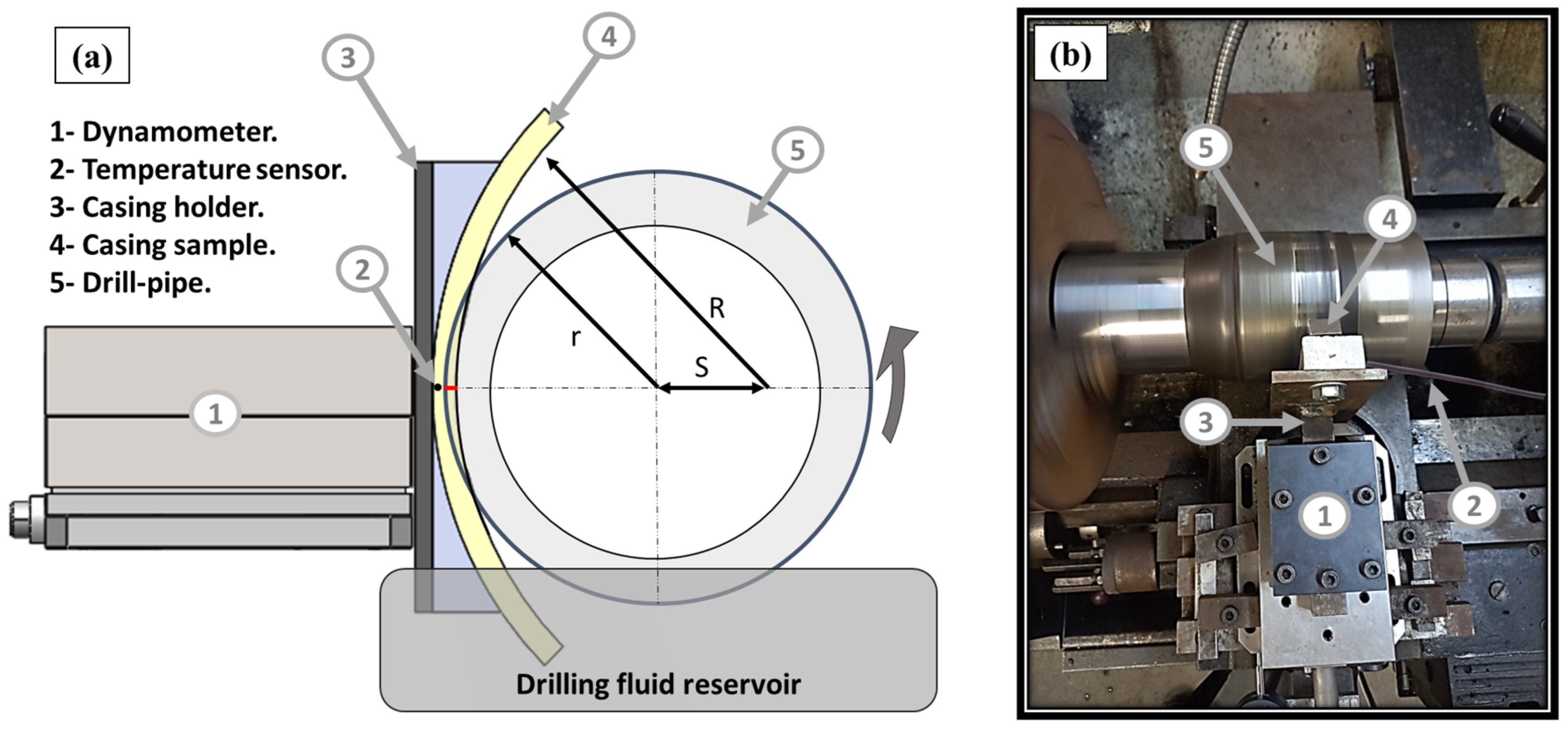
2.1. Experimental Procedure

A conventional lathe machine was modified, as shown in Figure 1, to carry out casing wear tests on SM2535-110. Various systems were designed and used to measure, control, and record test parameters such as applied side load, friction force, average casing temperature, and wear depth. The applied side load was determined by a dynamometer type 9139AA (Kistler Instrument Corp, Hudson, NY, USA), which was maintained and controlled by a microprocessor and a stepper motor connected to a reduction gearbox. More details of the established casing wear testing setup can be found in our previous studies [13,14,15]. A 25 mm wide sixty-degree circular section of the casing was machined from a real casing pipe and used as a casing sample.
A waterproof DS18B20-type digital temperature sensor was introduced through a hole in the casing sample at around 5 mm from the interface between the casing and DP-TJ. Testing was performed under OBM and WBM real drilling fluids with densities of 80 pcf and 70 pcf, respectively. The detailed characteristics of the muds which were provided by a local oil company were reported in earlier studies [14,15]. Furthermore, a Rheometer 702e was used to measure OBM and WBM viscosity at 25 °C. OBM had an average viscosity of 478 mPa.s at ambient temperature, while WBM had a viscosity of roughly 182 mPa.s.
Three altered different side loadings of a magnitude of 1 kN, 1.2 kN, and 1.4 kN were chosen to result in pressures that are within the reported field conditions of 0.3 to 0.5 MPa. The rotational speeds of 115 rpm (76 cm/s), 154 rpm (102 cm/s), and 207 rpm (137 cm/s) are close to the common drill string speed range of 100 to 120 rpm [5].
The crescent’s worn volume per unit width (mm3/mm), shown in Figure 2, may be estimated by Equation (1) if the maximum depth of the wear (w) in mm, casing inner radius (R) in mm, and drill pipe outer radius (r) in mm are known.
W e a r   v o l u m e = 12 β r 2 + 2 Q Q R Q S Q r R 2
With:
Q = R + r + S 2 , S = R r w ,
cos α = a r c t g     R 2 + S 2 r 2 2 R S   ,
β = a r c t g   R   s i n   α R   c o s   α S
The maximum wear depth used in Equation (1) was monitored and recorded during each of the tests, with a digital indicator that has a 0.001 mm resolution and accuracy of ±0.004 mm. The maximum wear depth values were then used to calculate the average wear volume.
The chemical compositions of the SM2535-110 casing steel, the drill pipe, and DP-TJ utilized in this are illustrated in Table 1 and the mechanical properties along with the dimensions of the casings are given in Table 2. An XD105 TM Pipe drill body grade that has a 100 mm (4 in) outer diameter and an XT TM 39 tool-joint connection type with a 124 mm (4.875 in) outer diameter were used [21].

2.2. Characterization

The hardness of the as-received casing, drill pipe, and DP-TJ was measured using the INNOVA-model 783-D Rockwell hardness machine (INNOVATEST, Maastricht, The Netherlands), with a conical diamond indenter and applied load of 150 kgf.
The chemical constituents of the tested samples were determined by plasma optical emission spectrometry ICP-OES PlasmaQuant® PQ 9000 (Analytik Jena, Jena, Germany).
To investigate the wear characteristics of the tested specimens, digital microscopic images (DMI) and scanning electron microscope (SEM) micrographs were captured using a high-performance SEM type JSM-6610LV low vacuum with an Oxford INCA, Energy Dispersive System (EDS), and Microscope Image Capture System (MICS) that has a magnification of 5 to 300,000 times and a resolution of 3 nm.

3. Results and Discussions

3.1. Elemental Composition and Hardness Evaluation

The chemical constituent of the SM2535-110 casing was determined at four distinct locations and the results showed that the tested casing specimens have carbon, chromium, nickel, and molybdenum contents of 0.02%, 25.7%, 32.0%, and 4.1%, respectively. These findings demonstrate strong concordance with the chemical composition of SM2535-110 casing steel as specified by the API SPEC 5CT standard [19].
The average values of ten hardness measurements of the received casing samples, drill pipe, and DP-TJ are illustrated in Table 3. The SM2535-110 casing sample’s measured hardness values agree with those reported in the API SPEC standard (≤33 HRC).

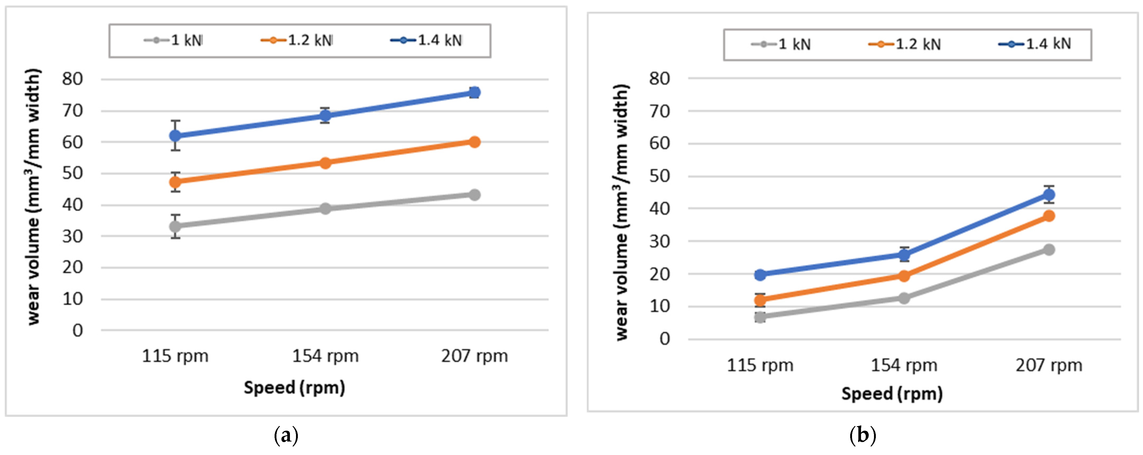
3.2. Casing Wear Depth and Volume

The maximum wear depth was periodically obtained every two minutes with the digital indicator and the values were recorded. Figure 3a displays the maximum wear depth of the SM2535-110 measured under WBM at a fixed speed and two side loads (1 K and 1.4 kN). On the other hand, Figure 3b displays the maximum wear depth measured under WBM at a fixed load and two rotating speeds. As can be observed, the maximum wear becomes an almost linear function of time after a wear-in period of around 10 min. The overall maximum wear depth after 60 min increases by more than 100% when the load passes from 1 kN to 1.4 kN at 115 rpm. However, after changing the speed from 115 rpm to 207 rpm under 1.4 kN applied side load, the total maximum wear depth has only increased by 50%.
The volume loss of SM2535-110 casing specimens calculated using Equation (1) at various loads and speeds for OBM and WBM lubrication is illustrated in Figure 4. It is observed that irrespective of the mud type, the wear volume increases with both the contact load and rpm. It is important to note that the high coefficient of friction of the DP-TJ/SM2535-110 casing specimens under both OBM and WBM caused the SM2535-110 casing sample to exhibit a high specific wear volume and wear rate.
To understand how the drilling mud type affects the COF at different operating conditions, friction-wear tests were conducted for all SM2535-110 casing specimens at (1.4 kN, 1.2 kN, 1 kN) and (207 rpm, 154 rpm, 115 rpm) under WBM and OBM. An example of the average values of the COF for the samples tested at 207 rpm and 1.4 kN under WBM and OBM is revealed in Figure 5. It can be observed that the average COF under WBM (0.42) is higher than the COF under OBM (0.33). The average COF of SM2535-110 casings specimens tested at the different contact loads and DP speeds under WBM and OBM are illustrated in Figure 6. The general trend observed under both WBM and OBM is that the COF increases with both the side load and the rotational speed, N. The increase in COF with N can be explained by the increase in the Sommerfeld number with the rotational speed in the thick film hydrodynamic lubrication region since the test configuration is like that of the partial journal bearing. Based on the McKee brothers’ analysis, µN/P must be greater than 1.7 × 10⁻⁶ (reyn rps/psi) to keep a thick film hydrodynamic lubrication, where µ is the lubricant viscosity, N is the rotational speed in revolutions per second (rps), and P is the pressure on the projected contact area, in psi. In this case, µN/P equals 0.069 (reyn rps/psi) at 1.4 kN and 115 rpm, proving that hydrodynamic lubrication is present [22].
Furthermore, the average casing temperature profiles recorded during the test performed at 1.2 kN, 115 rpm, and 207 rpm under OBM and WBM are presented in Figure 7a and 7b, respectively. It is obvious that under WBM, the average temperature of SM2535-110 casing started to rise at a higher rate compared to casing specimens tested under OBM during the first 10 min, then kept on increasing at a lower rate until it reached 78 °C and almost remained constant. However, under OBM a completely different behavior was observed since the temperature started to increase almost linearly and it reached an average temperature of 56 °C at 115 rpm and 81 °C at 207 rpm and kept on increasing. This could be directly related to the difference in the wear mechanism under OBM compared to WBM, which will be discussed in the casing wear mechanism section. Figure 8a displays the typical casing temperature profile for SM2535-110 casing specimens tested in a WBM environment at 115 rpm and different contact loads. The average SM2535-110 casing temperature is shown to steadily rise at various rates and the maximum temperature measured after 60 min decreases as the side load decreases. On the other hand, the average SM2535-110 casing temperature increases as the DP-TJ speed increases from 115 rpm to 207 rpm at the same radial load of 1.2 kN, as shown in Figure 8b.

3.3. Specific Wear Rate of SM2535-110 Casing

The casing specific wear rate (K) in mm3/Nm was estimated using the following equation:
K = V/PL
With:
V: volume loss (mm3);
P: radial load (N);
L: total sliding distance (mm).
The estimated specific wear rate (K) values for SM2535-110 casing specimens tested under OBM and WBM and different rotational velocities and radial loads are illustrated in Table 4.
The specific wear rates obtained for SM2535-110 casing specimens, tested under the above-mentioned conditions are shown in Figure 9. Under OBM, the casing-specific wear rate varied from 140.9 × 10⁻⁶ mm3/Nm at 115 rpm and 1 kN side load to 295.26 × 10⁻⁶ mm3/Nm at 207 rpm and 1.4 kN. On the other hand, under WBM, the SM2535-110 casing-specific wear rate varied from 60.12 × 10⁻⁶ mm3/Nm at 115 rpm and 1 kN to 142.43 × 10⁻⁶ mm3/Nm at 207 rpm and 1 kN. These K values are 10 to 50 times higher than those obtained for martensitic steel casing materials P110 and L80 reported in earlier studies [15,16]. This is mostly because of the minimal carbon content of SM2535-110 compared to P110 and L80. As reported earlier, the wear resistance of steel is a linear function of the square root of the carbon weight percent [23]. Furthermore, austenitic stainless steels are known to have insufficient tribological properties.

3.4. Drilling Mud Type Effect on Wear Factor

It can be seen from Figure 10a,b that the wear factors under WBM are lower as compared to those under OBM, which was in contradiction to what was expected. Since the viscosity of OBM is higher than WBM, it was expected to show better lubricating properties. Hence, to investigate this contradiction, a simple experiment was designed and conducted to check the variation in the hardness of the sample surface during the wear test under WBM and OBM, respectively. It is to be noted that during the wear process, there will be an increase in the localized temperature of the surface. However, the lubrication helps in dissipating this heat rapidly from the contact region, due to which the surface will be subjected to a rapid cooling because the surface gets work-hardened, resulting in an increase in the hardness and the formation of a thin film protective layer since the WBM contains Cl- [7]. Hence, the following simple experiment was designed. Three specimens of SM2535-110 casing were sectioned and then heated inside a furnace to 300 °C, 450 °C, and 600 °C for 30 min then rapidly cooled in water (quenched). The hardness of the sectioned specimens was then measured to study the heat treatment effect on the hardness of the SM2535-110 specimens and the results are shown in Figure 11. It can be seen that the hardness of the surface increased with the increasing temperature, which can be attributed to microstructural changes. As can be seen from Figure 12, the hardness values under OBM were lower as compared to that under WBM, which may have contributed to the higher wear resistance of the surface under WBM as compared to that under OBM due to the combined effect of microstructural changes, the work hardening of the surface, and the formation of a thin film protective layer.

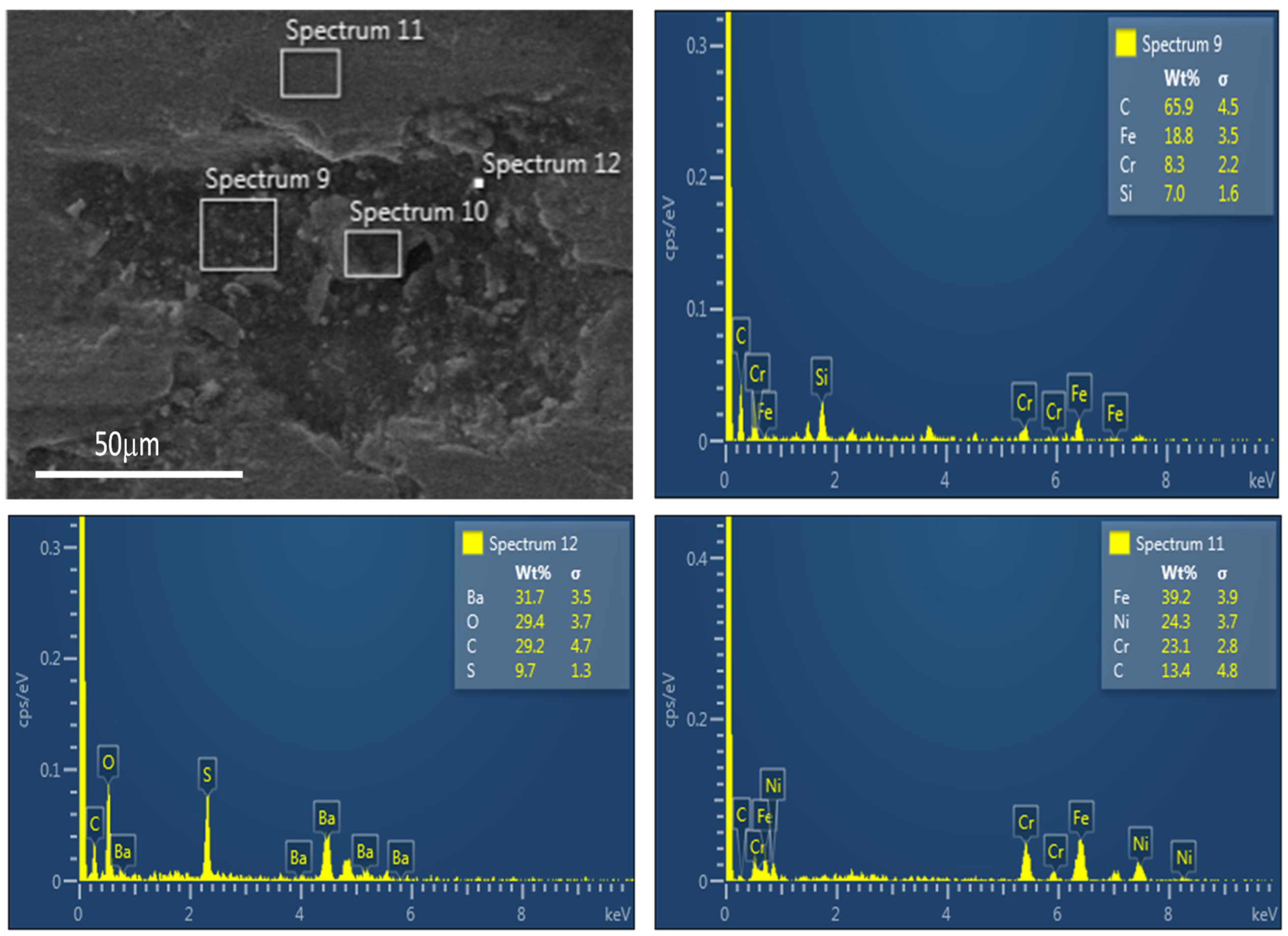
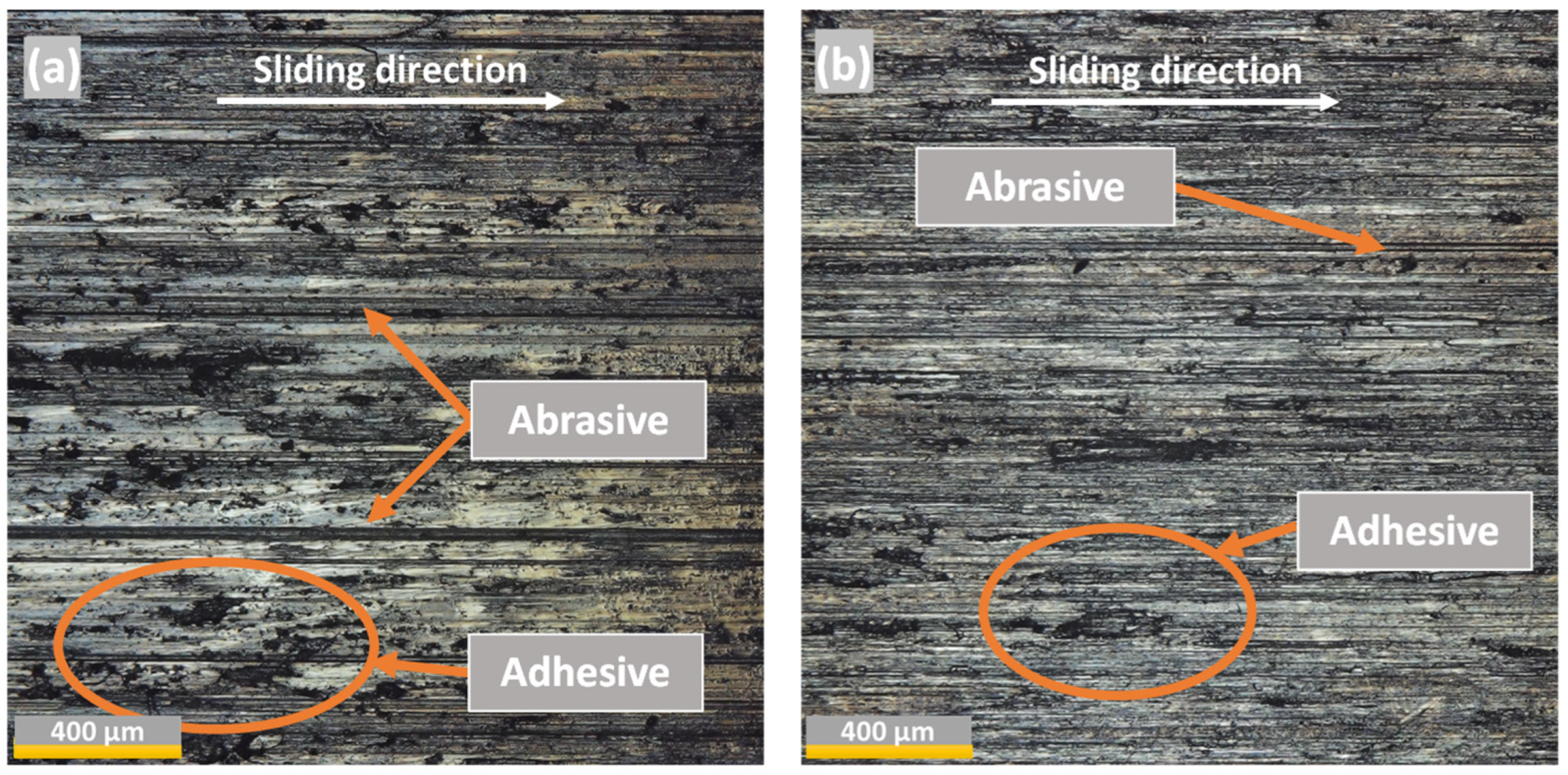
3.5. Wear Mechanisms of SM2535-110 Casing

SEM micrographs of the worn surfaces of SM2535-110 casing specimens, tested under OBM and WBM at 207 rpm and 1.4 kN, are presented in Figure 13 and Figure 14, respectively. These micrographs reveal that both adhesive and abrasive wear are present under OBM and that abrasion is the leading wear mechanism, while under WBM a combination of adhesion and plastic deformation was observed. It is worth mentioning that under WBM lubrication at different spots, the material was detached from the surface and reattached again, as proven by EDS analysis carried out at the worn area, illustrated in Figure 15. It can be seen that the newly reattached and squeezed flakes have the same composition as the original material and they have been work-hardened. On the other hand, some solid particles originating from the WBM were observed on the surface, which is believed to be the cause of the three-body abrasive wear.
To explore the effect of the side loading on the SM2535-110 casing wear mechanism, DMI images were captured at the worn area for selected specimens. The DMI of the worn casing samples tested under OBM at 154 rpm and two contact loads of 1 kN and 1.4 kN are illustrated in Figure 16. It can be seen that under OBM, abrasive wear is dominant with the severity of the wear increasing with the side load. The DMI of the specimens tested under WBM at 154 rpm and two side loads of Figure 17 reveal that both adhesion and abrasion were noticed at low and high side loads. Yet, the adhesive wear becomes more dominant as the side load increases from 1 kN to 1.4 kN and the severity of the wear increases as well.
Figure 18 illustrates the side load effects on the wear mechanisms of SM2535 tested at 1.4 kN under OBM and WBM. We noticed that at 1.4 kN and a lower speed of 115 rpm under OBM, the primary wear mechanism is abrasive wear, and the abrasive wear becomes dominant as the DP-TJ speed increases to 207 rpm. As opposed to that, a work-hardened reactive layer is observed under WBM at lower and higher speeds and both adhesion and abrasion are observed. We also noticed that under WBM as the DP-TJ speed increases, the wear becomes more aggressive, but it is lower than under OBM for the same conditions, as shown in Figure 18. This can be attributed to the combined effect of microstructural changes, the work-hardening of the surface, and the formation of a thin film protective layer, as discussed above [9].

4. Conclusions

Casing wear experiments were carried out on austenitic stainless SM2535-110 under OBM and WBM under three rotational speeds and three different side loads. The experimental results revealed that:
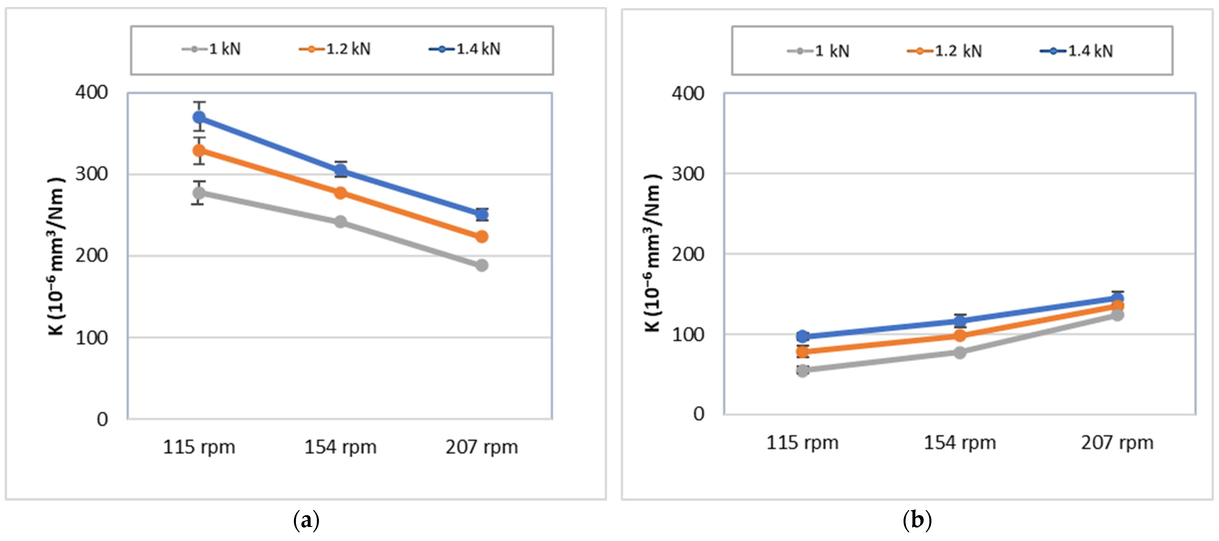
  • Under both OBM and WBM, the specific wear rate increases with increasing side load due to the increase in the real area of contact.
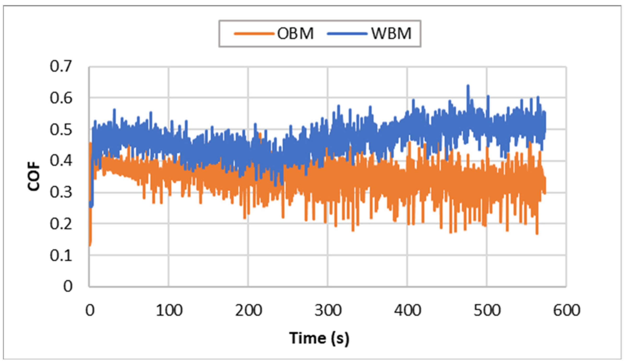
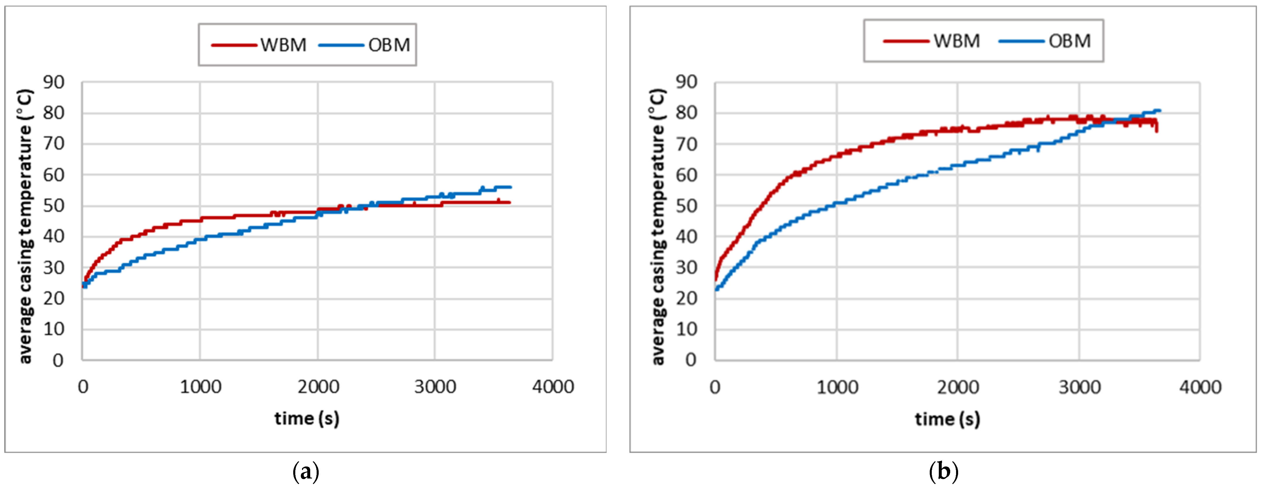
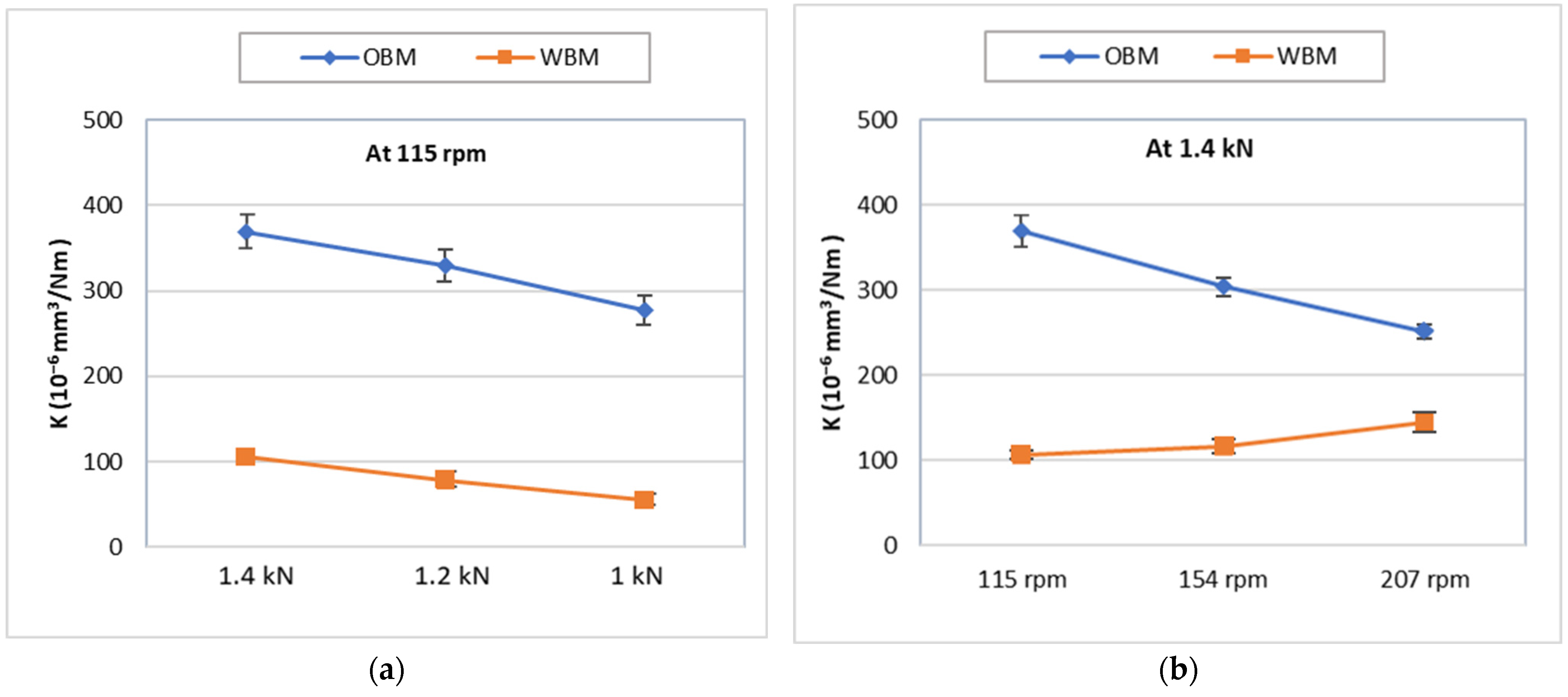
  • The casing wear factor decreases with increasing rotational speed for specimens tested under OBM while it increases for specimens tested under WBM. The first is mainly due to the change in the lubrication regime from boundary to hydrodynamic lubrication at higher speeds, while the second is due to the lower viscosity of the WBM and the higher COF.
  • The specific wear rate of specimens tested under WBM is two to three times lower than that tested under OBM.
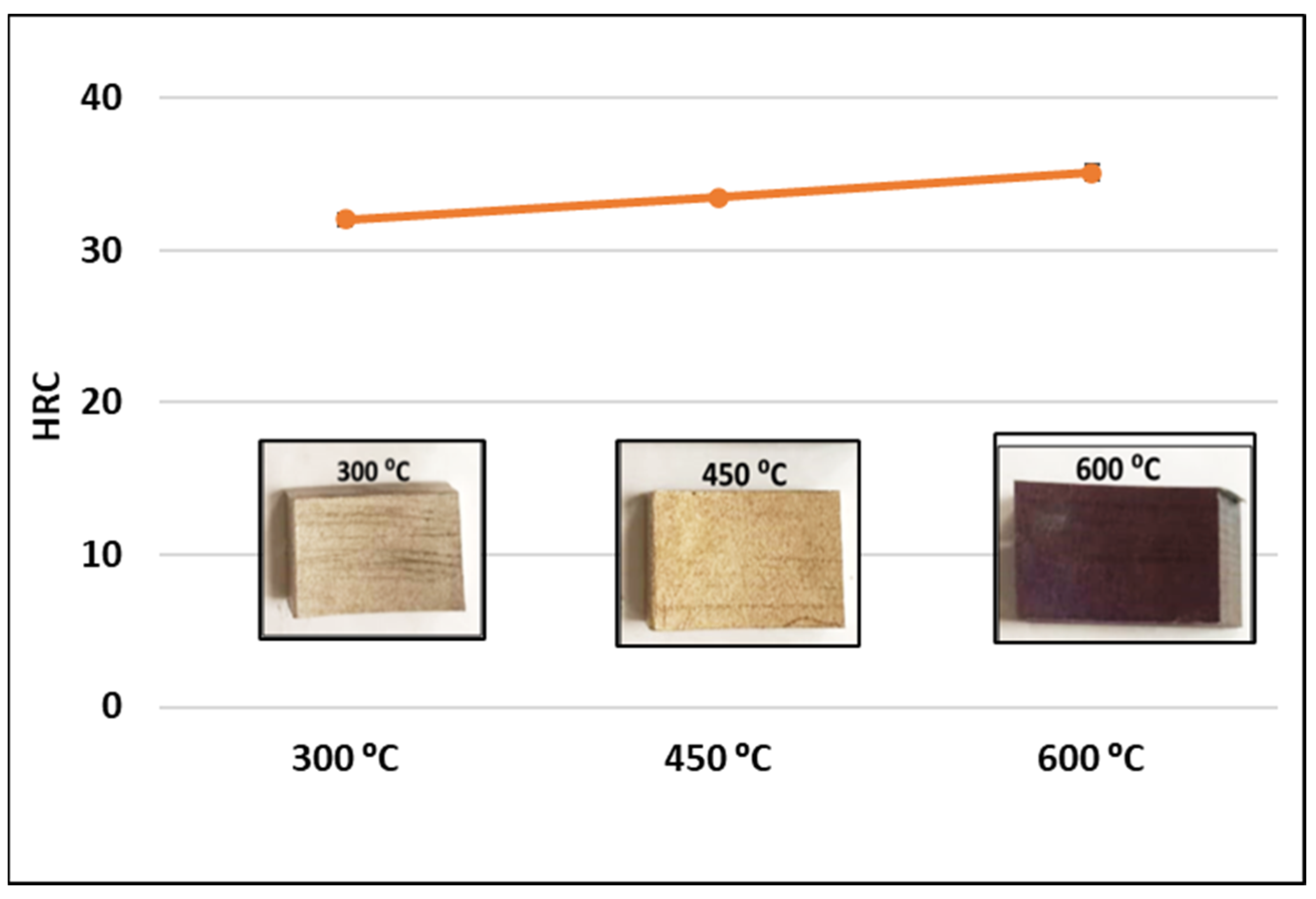
  • The hardness values under OBM were lower as compared to that under WBM, which may have contributed to the higher wear resistance of the surface under WBM as compared to that under OBM due to the combined effect of microstructural changes, the work hardening of the surface, and the formation of a thin film protective layer.
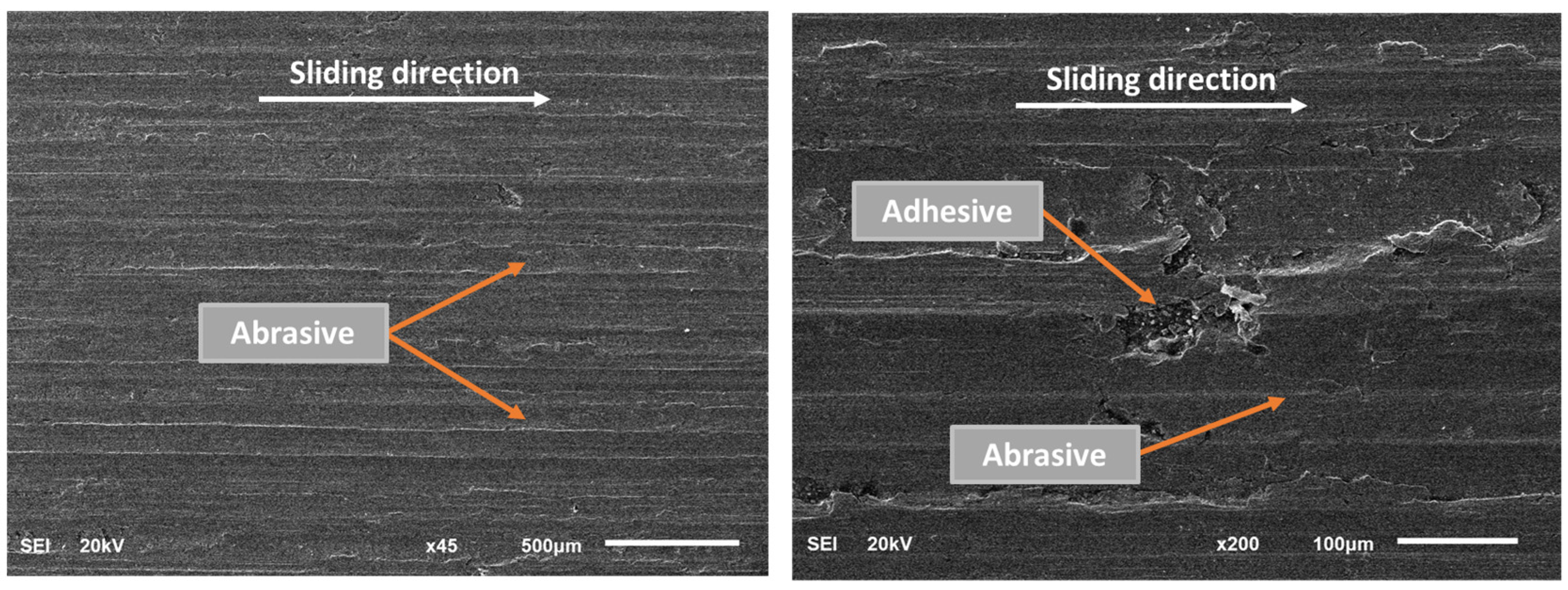
  • The primary wear mechanism under OBM was abrasion, whereas the primary wear mechanism with WBM lubrication was adhesion and plastic deformation, especially at high side loads.

Author Contributions

Conceptualization, N.M. and O.O.; methodology, N.M., O.O. and M.A.S.; formal analysis, O.O., N.M. and M.A.S.; investigation, O.O. and N.M.; resources, O.O., N.M., M.A.S., A.A.-S. and M.A.; data curation, O.O. and N.M.; writing—original draft preparation, O.O. and N.M.; writing—review and editing, O.O., N.M., M.A.S., A.A.-S. and M.A.; supervision, N.M.; project administration, N.M.; funding acquisition, N.M. All authors have read and agreed to the published version of the manuscript.

Funding

This work along with the APC is funded by the KFUPM Deanship of Research Oversight and Coordination (DROC) through project # ME002499.

Data Availability Statement

All supporting data are provided in this paper.

Acknowledgments

The authors would like to acknowledge the support of KFUPM Deanship of Research Oversight and Coordination (DROC). The casings, drilling pipes, and drilling fluids were provided by the Drilling Department of Saudi Aramco.

Conflicts of Interest

The authors declare no conflict of interest.

References

  1. Fischer, A.; Bobzin, K. Friction, Wear and Wear Protection: International Symposium on Friction, Wear and Wear Protection 2008, Aachen, Germany; Wiley: Weinheim, Germany, 2009; ISBN 352732366X. [Google Scholar]
  2. Andersson, S. Wear Simulation with a Focus on Mild Wear in Rolling and Sliding Contacts. In Friction, Wear and Wear Protection; Wiley-VCH Verlag GmbH & Co. KGaA: Weinheim, Germany, 2011; pp. 1–19. [Google Scholar]
  3. Huimei, W.; Yishan, L. The Influence of Drilling Parameters on Casing Wear in Ultra-Deep Directional Well. In ICPTT 2012: Better Pipeline Infrastructure for a Better Life; American Society of Civil Engineers: Reston, VA, USA, 2013; pp. 920–926. [Google Scholar]
  4. Gao, D.; Sun, L.; Lian, J. Prediction of Casing Wear in Extended-Reach Drilling. Pet. Sci. 2010, 7, 494–501. [Google Scholar] [CrossRef]
  5. Williamson, J.S. Casing Wear: The Effect of Contact Pressure. J. Pet. Technol. 1981, 33, 2382–2388. [Google Scholar] [CrossRef]
  6. Rădăcină, D.; Halafawi, M.; Avram, L. Casing Wear Prediction in Horizontal Wells. Pet. Coal 2020, 62, 395–405. [Google Scholar]
  7. Zhang, Q.; Lian, Z.; Lin, T.; Deng, Z.; Xu, D.; Gan, Q. Casing Wear Analysis Helps Verify the Feasibility of Gas Drilling in Directional Wells. J. Nat. Gas Sci. Eng. 2016, 35, 291–298. [Google Scholar] [CrossRef]
  8. Best, B. Casing Wear Caused by Tooljoint Hardfacing. SPE Drill. Eng. 1986, 1, 62–70. [Google Scholar] [CrossRef]
  9. Doering, A.E.R.; Danks, D.R.; Mahmoud, S.E.; Scott, J.L. Evaluation of Worn Tubulars from DEA-42 and Small-Scale Casing Wear Testers. In Proceedings of the Offshore Technology Conference, Houston, TX, USA, 2–5 May 2011. [Google Scholar]
  10. Yu, H.; Lian, Z.; Lin, T.; Liu, Y.; Xu, X. Experimental and Numerical Study on Casing Wear in Highly Deviated Drilling for Oil and Gas. Adv. Mech. Eng. 2016, 8, 1687814016656535. [Google Scholar] [CrossRef]
  11. Chen, Y.; He, C.; Zhou, X.; Yu, H. Analysis of Factors Affecting Drilling Friction and Investigation of the Friction Reduction Tool in Horizontal Wells in Sichuan. Adv. Mech. Eng. 2019, 11, 1687814019862963. [Google Scholar] [CrossRef]
  12. Yu, H.; Lian, Z.; Lin, T.; Zhu, K. Experimental and Numerical Study on Casing Wear in a Directional Well under in Situ Stress for Oil and Gas Drilling. J. Nat. Gas Sci. Eng. 2016, 35, 986–996. [Google Scholar] [CrossRef]
  13. Osman, O.A.; Merah, N.; Samuel, R.; Alshalan, M.; Alshaarawi, A. Casing Wear Tests for Precise Wear Factor Evaluation. In Proceedings of the IADC/SPE International Drilling Conference and Exhibition, Galveston, TX, USA, 8–12 March 2022. [Google Scholar] [CrossRef]
  14. Osman, O.A.; Merah, N.; Abdul Samad, M.; Baig, M.M.A.; Samuel, R.; Alshalan, M.; Alshaarawi, A. Casing Wear and Wear Factors: New Experimental Study and Analysis. Materials 2022, 15, 6544. [Google Scholar] [CrossRef] [PubMed]
  15. Osman, O.; Merah, N.; Samad, M.; Baig, M.; Samuel, R.; Alshalan, M.; Alshaarawi, A. Wear Factors and Mechanisms of L-80 Steel Casings. Eng. Res. Express 2023, 5, 025076. [Google Scholar] [CrossRef]
  16. Sridhar, N.; Thodla, R.; Gui, F.; Cao, L.; Anderko, A. Corrosion-Resistant Alloy Testing and Selection for Oil and Gas Production. Corros. Eng. Sci. Technol. 2018, 53, 75–89. [Google Scholar] [CrossRef]
  17. Al-Saeedi, M.J.; Al-Enezi, D.; Sounderrajan, M.; Saxena, A.K.; Gumballi, G.K.; McKinnell, D.C. First Implementation of CRA Casing in Sour HPHT Reservoirs in Deep Wells in Kuwait. In Proceedings of the North Africa Technical Conference and Exhibition, Cairo, Egypt, 15–17 April 2013; p. SPE-164603-MS. [Google Scholar]
  18. Li, L.F. Corrosion-Resistant Alloys for Tubings and Casings and Alloy Material Selection in Oil and Gas Wells. Adv. Mater. Res. 2013, 690–693, 276–279. [Google Scholar] [CrossRef]
  19. Nippon Steel Tubular Products. Available online: https://www.tubular.nipponsteel.com/octg-material/data-sheet/sm2535-110 (accessed on 23 November 2022).
  20. Moore, M.A. The Relationship between the Abrasive Wear Resistance, Hardness and Microstructure of Ferritic Materials. Wear 1974, 28, 59–68. [Google Scholar] [CrossRef]
  21. API 5CT Chemical Composition of Casing Pipe. Available online: https://www.hu-steel.com/product89_991.html (accessed on 5 March 2022).
  22. Yaqoob, M.S.T. Empirical Analysis of Localized Casing Wear with Variations in Contact Pressure and Drilling Conditions. Ph.D. Thesis, Technische Universität Clausthal, Clausthal-Zellerfeld, Germany, 2021. [Google Scholar]
  23. Stachowiak, G.W.; Batchelor, A.W. Introduction. In Engineering Tribology; Elsevier: Amsterdam, The Netherlands, 2006; pp. 1–9. [Google Scholar]
Figure 1. The casing wear test setup where (a) is the 2D drawing of the setup and (b) is a photo of the setup.
Lubricants 11 00420 g001
Figure 2. Crescent-shape wear groove [15].
Lubricants 11 00420 g002
Figure 3. The maximum wear depth of the SM2535-110 casing wear measured under WBM at (a) 115 rpm and two loads and (b) 1.4 kN and two speeds.
Lubricants 11 00420 g003
Figure 4. The wear volume of SM2535-110 casing specimens tested at different contact loads and three rpm values under (a) OBM and (b) WBM.
Lubricants 11 00420 g004
Figure 5. Example of the COF of the DP-TJ/SM2535-110 casing specimens tested at 154 rpm and 1.4 kN under WBM and OBM.
Lubricants 11 00420 g005
Figure 6. Average values of COF of SM2535-110 casing specimens at three applied side loadings and spinning speeds under (a) OBM and (b) WBM.
Lubricants 11 00420 g006
Figure 7. Example of SM2535-110 casing specimens’ average temperature measured under OBM and WBM during the wear test at 1.2 kN and rotational speed of (a) 115 rpm and (b) 207 rpm.
Lubricants 11 00420 g007
Figure 8. Average temperature of SM2535-110 casing specimens tested under WBM at (a) at 115 rpm constant speed and (b) at 1 kN constant load.
Lubricants 11 00420 g008
Figure 9. The specific wear rate of SM2535-110 casing specimens tested at different loads and speeds under (a) OBM and (b) WBM.
Lubricants 11 00420 g009
Figure 10. The specific wear rate of SM2535-110 casing tested under WBM and OBM at (a) 115 rpm; (b) 1.4 kN.
Lubricants 11 00420 g010
Figure 11. The hardness of SM2535 casing after heating the specimens for 30 min each at various temperatures followed by rapid cooling in water.
Lubricants 11 00420 g011
Figure 12. The hardness values of SM2535-110 casing tested at 1 kN and three speeds under both WBM and OBM lubrication.
Lubricants 11 00420 g012
Figure 13. SEM micrographs of SM2535-110 casing specimen tested at 207 rpm and 1.4 kN under OBM.
Lubricants 11 00420 g013
Figure 14. SEM micrographs of SM2535-110 casing sample subjected to 1.4 kN at 207 rpm and under WBM.
Lubricants 11 00420 g014
Figure 15. EDS analysis of worn SM2535-110 casing specimen subject to a side load of 1.4 kN at 207 rpm and under WBM lubrication.
Lubricants 11 00420 g015
Figure 16. DMI of SM2535-110 casing specimens tested at 154 rpm under OBM conditions at (a) 1.4 kN and (b) 1 kN.
Lubricants 11 00420 g016
Figure 17. DMI of SM2535-110 casing specimens tested at 154 rpm under WBM conditions at (a) 1.4 kN side load and (b) at 1 kN side load.
Lubricants 11 00420 g017
Figure 18. DMI of SM2535-110 casing specimens tested at 1.4 kN and different speeds under (a) OBM and (b) WBM.
Lubricants 11 00420 g018
Table 1. Elemental compositions of SM2535 casing, drill pipe, and DP-TJ [19].
ElementsSM2535-110Drill PipeCounterface
(DP-TJ)
Fe35.5%96.2%92.4%
C0.02%0.4%0.9%
Cr25.7%1.4%3.8%
Ni32%0%0%
Mo4.1%0%0%
Mn0.7%0%0%
Table 2. Mechanical properties of SM2535-110 steel casing.
Casing PropertyUnitValues
Ultimate tensile strength value(MPa)≥792
Yield strength value(MPa)758–965
Casing hardness value(HRC)≤33
Outer DP diameter(mm) [in](245) [9–5/8]
Casing thickness(mm) [in](110) [0.44]
Table 3. Average hardness of the three materials and drill pipe.
SM2535-110Counterface (DP-TJ)
Hardness31.73 ± 1.957.94 ± 0.8
Table 4. Specific casing wear rate (K) of SM2535-110 specimens.
Type of MudSample NumberSpeed (rpm)Side Load (kN)K (10−6 mm3/Nm)
OBMS11151277.13
S21151.2329.53
S31151.4369.52
S41541241.66
S51541.2277.42
S61541.4304.82
S72071188.38
S82071.2223.17
S92071.4251.06
WBMS10115154.88
S111151.278.48
S121151.4106.27
S13154177.33
S141541.298.12
S151541.4115.81
S162071124.05
S172071.2134.85
S182071.4144.4
Disclaimer/Publisher’s Note: The statements, opinions and data contained in all publications are solely those of the individual author(s) and contributor(s) and not of MDPI and/or the editor(s). MDPI and/or the editor(s) disclaim responsibility for any injury to people or property resulting from any ideas, methods, instructions or products referred to in the content.

