Article

Numerical Investigations of Static and Dynamic Characteristics of a Novel Staggered Labyrinth Seal with Semi-Elliptical Structure

1
College of Energy and Power Engineering, Nanjing University of Aeronautics and Astronautics, Nanjing 210016, China
2
AECC Guizhou Honglin Aero-Engine Control Technology Co., Ltd., Guizhou 550009, China
3
School of Energy and Power Engineering, Jiangsu University, Zhenjiang 212013, China
*
Author to whom correspondence should be addressed.
Lubricants 2024, 12(5), 169; https://doi.org/10.3390/lubricants12050169
Submission received: 27 March 2024 / Revised: 2 May 2024 / Accepted: 7 May 2024 / Published: 10 May 2024

Abstract

:
In order to optimize sealing performance, a novel labyrinth seal with semi-elliptical teeth (SET) structure is proposed in this paper, which includes semi-elliptical teeth and a series of cavities. The simulation results calculated by the numerical methods are compared with the experimental and theoretical results, and static and dynamic characteristics of the novel SET structure are further investigated. The numerical simulations of labyrinth seals with the SET structure demonstrate high accuracy and reliability, with a maximum relative error of less than 6% as compared to experimental results, underscoring the validity of the model. Notably, leakage rates are directly influenced by pressure drop and axial offset, with optimal sealing achieved at zero axial displacement. The direct damping coefficient increases as the pressure drop increases while the other dynamic coefficients decrease. Additionally, the stability results show that the novel SET structure exhibits higher stability for positive axial offsets. The novel model and corresponding results can provide a meaningful reference for the study of sealing structure and coupled vibration in the field of fluid machinery.

1. Introduction

Centrifugal pumps are an important class of rotating machinery that has garnered significant attention over recent years [1,2,3,4]. The effectiveness of the sealing structure is crucial for ensuring the safety, reliability and economy of centrifugal pumps. With the increasing demand for high-performance and large-capacity rotating machinery, there is a need for improved sealing performance. Therefore, improving sealing performance, reducing leakage and extending service life for centrifugal pumps operating under demanding conditions are of great significance. Labyrinth seals, celebrated for their superior sealing capabilities and durability, are prevalently employed in industry [5]. In rotor systems, the labyrinth sealing system, constituted by an assembly of cavities and teeth, plays a vital role in mitigating fluid leakage between the rotor and stator [6]. The leakage reduction is attributed to the sealing teeth gap’s throttling effect and the kinetic energy’s dissipation within the sealing chamber, where the pressure energy, diminished during passage through the labyrinth seal gap, is converted into kinetic energy and subsequently dissipated as heat due to the significant friction in the rough-surfaced slit.
From the initial simple exploration to intensive research, many scholars have conducted a lot of research on the labyrinth seal over the past few decades. In the early days, due to the restriction of technical level, researchers could only combine experimental research and thermodynamic analysis to conduct preliminary exploratory research. However, the advent and widespread adoption of numerical simulation technology have enabled the investigation of more intricate flow structures and sealing characteristics. Recent studies by Kim and Cha using CFD simulations have delved into the leakage characteristics of straight-through and stepped labyrinth seals, revealing the stepped configuration’s superior leakage reduction capabilities [7]. Zhang et al. [8] explored the static characteristics of labyrinth seals under various eccentricities and inlet pressures, both theoretically and experimentally. Further contributions include Qin et al.’s investigation into the flow characteristics of a non-rotating labyrinth seal with a right-angle trapezoidal throttle tooth design [9]. Zhang et al. [10] proposed a novel hole-pattern damping seal with inclined holes, which presented good leak-proof performance. Zhou et al. [11] proposed a novel labyrinth seal with staggered helical teeth (SHT) structure, which has better leakage performance compared with ordinary helical teeth (OHT) structure.
In addition to the research on static characteristics, the dynamic characteristics of labyrinth seals have also been a focal point of research. Hirs [12] used the Blasius friction coefficient formula to establish the viscous friction model, which provided the theoretical foundation for analyzing the dynamic characteristics of labyrinth seals. Subsequent studies have introduced various methods and models for calculating labyrinth seals’ dynamic characteristic coefficients [13,14,15]. Saber et al. [16] carried out a theoretical study to investigate the effect of transverse asymmetry of the shaft on the dynamic characteristics of labyrinth seals for different geometries. Zhang et al. [17,18] proposed a new hole-diaphragm-labyrinth seal (HDLS) structure constructed by adding a single hole to the diaphragm from a conventional diaphragm-labyrinth seal (DLS) by introducing an additional damping source. Sun et al. [19] analyzed how the dynamic characteristics of a sealed rotor were affected by shunt injection and an improved impedance method based on unbalanced synchronous excitation was proposed. Zhai et al. [20,21] proposed the theoretical solutions for dynamic coefficients of spiral-grooved and herringbone groove seals according to the perturbation method. Based on the porous medium model and whirling rotor method, Zhang et al. [22] revealed the effects of operating conditions on rotor dynamic coefficients for the different seal configurations by the numerical model. Wu et al. [23] employed the multi-frequency dynamic mesh technique by Li [24] to calculate the dynamic characteristics of various types of seals. Their research examined changes in the dynamic characteristics of different seals, ranging from sub-frequency to super-frequency whirl. In the study, they discovered that the cross-coupled stiffness turns negative at sub-synchronous frequencies below the rotor speed.
A periodic excitation force caused by the sealing structure on the rotor could cause rotor instability and vibration when the rotor rotates periodically [25,26]. The performance of the upper-end seal structure of the molten salt pump was calculated, and the correlation between key variables such as heads, viscosities and sealing performance of the upper end was summarized by Jin et al. [27]. Zhang et al. [28] proposed the interpolation database method (IDM) to examine the dynamic response of circumferentially discontinuous seals. The IDM demonstrates enhanced accuracy in the calculation of the nonlinear vibration characteristics of the rotor-seal system. The main reason for the unsteady tangential force was the circumferential helical flow. Zhang et al. [29] proposed a new helix-comb seal (HCS) to control the circumferential helical flow and reduce the unsteady tangential force. In addition, the HCS had superior tangential force reduction capability compared to the traditional labyrinth seal. Xue et al. [30] proposed the incorporation of partition walls and helical teeth into traditional labyrinth seal structures. The presence of partition walls and helical teeth significantly reduces the cross-coupling stiffness of the labyrinth seal structure.
Although there are a lot of studies on the labyrinth seal structure, there exist relatively few studies on the elliptical labyrinth seal with liquid medium. The behavior of liquid, characterized by properties such as higher density and viscosity compared to gas, significantly alters the sealing performance and dynamic interactions within the seal structure. In this paper, a staggered labyrinth seal with SET structure is proposed, introducing a unique integration of semi-elliptical teeth within a staggered arrangement to optimize fluid dynamic interactions and sealing efficiency. The leakage and dynamic characteristic coefficients of this novel staggered labyrinth sealing structure with SET structure are studied using CFD simulation technology after experimental verification. The staggered labyrinth sealing structure with SET structure has good sealing performance, which can be further applied in the centrifugal pump system to replace the existing smooth annular seal structure.

2. The Novel Labyrinth Seal with SET Structure

2.1. Geometric Model

The staggered labyrinth seal, incorporating a semi-elliptical tooth (SET) design, is depicted schematically in Figure 1. This figure outlines the general configuration of the seal. Figure 2 shows the radial profile and main parameters of the novel SET structure. The main parameters of the labyrinth seal with the SET structure are seal length (L), seal clearance (Cr), tooth number (Z), tooth height (H), staggered tooth spacing (Lg), cavity width (B1), and tooth width (B2), which are listed in Table 1. The labyrinth seal structure features a staggered seal design with a semi-elliptical labyrinth tooth ring on the rotor. Additionally, an extended outlet section is utilized to investigate flow conditions at the end of the labyrinth seal and prevent any adverse backflow effects in computational results. This innovative design enhances the friction and bunching effects, resulting in improved sealing performance.

2.2. Numerical Simulation Method

For the numerical calculations, the standard k-ε turbulence model is employed due to its derived dissipation rate equation from the precise vortex pulsation equation, ensuring the accuracy and reliability of the simulation outcomes. The study investigates the leakage performance by examining variations in parameters such as pressure drops, axial offsets of rotor teeth, rotation speeds and seal clearances. In this study, a scalable wall function is employed. The calculated Y+ value for all walls falls within the permitted range of a scalable wall function requirement, spanning from 15 to 20. The turbulence boundary is a combination of intensity and hydraulic diameter, with a turbulence intensity of 5% of the default value. The working medium is liquid water with a density of 998.2 m3/kg, and the entire working field rotating at 1450 r/min. To simulate realistic operating conditions, pressure boundary conditions are applied at both inlet and outlet boundaries to facilitate the desired pressure drop across the seal. Moreover, all remaining surfaces are treated as smooth, adiabatic and no-slip boundaries to accurately reflect physical conditions. To enhance the precision of the simulation results, the second-order upwind scheme is utilized for both turbulent kinetic energy and its dissipation rate. The results converged once the residuals reached a level of 10−6. A summary of the numerical parameters and details, including the boundary conditions, applied in the present investigation is presented in Table 2.

3. Computational Model Validation

3.1. Grid Independence Verification

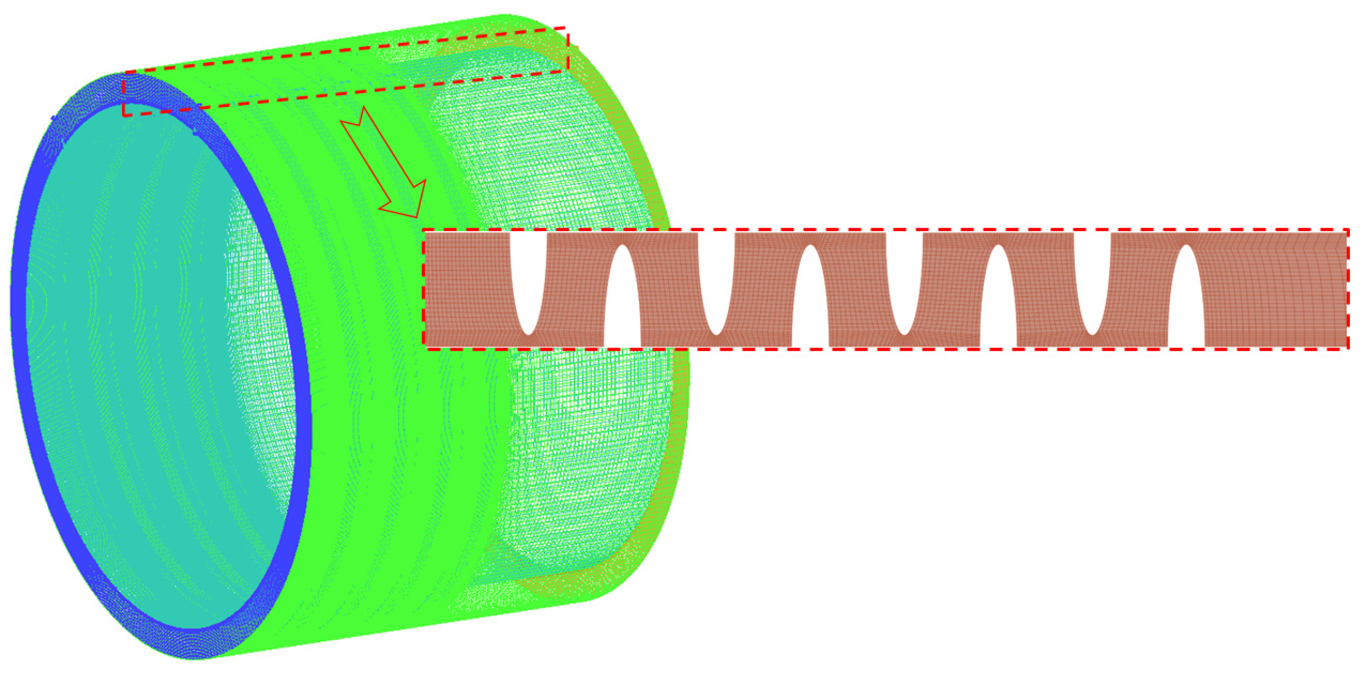
In contrast to unstructured grids, structured grids are characterized by good quality, high convergence accuracy and easy implementation of region boundary fitting. Therefore, the structured meshes are used to discretize the computational domain, and the corresponding working domain is shown in Figure 3.
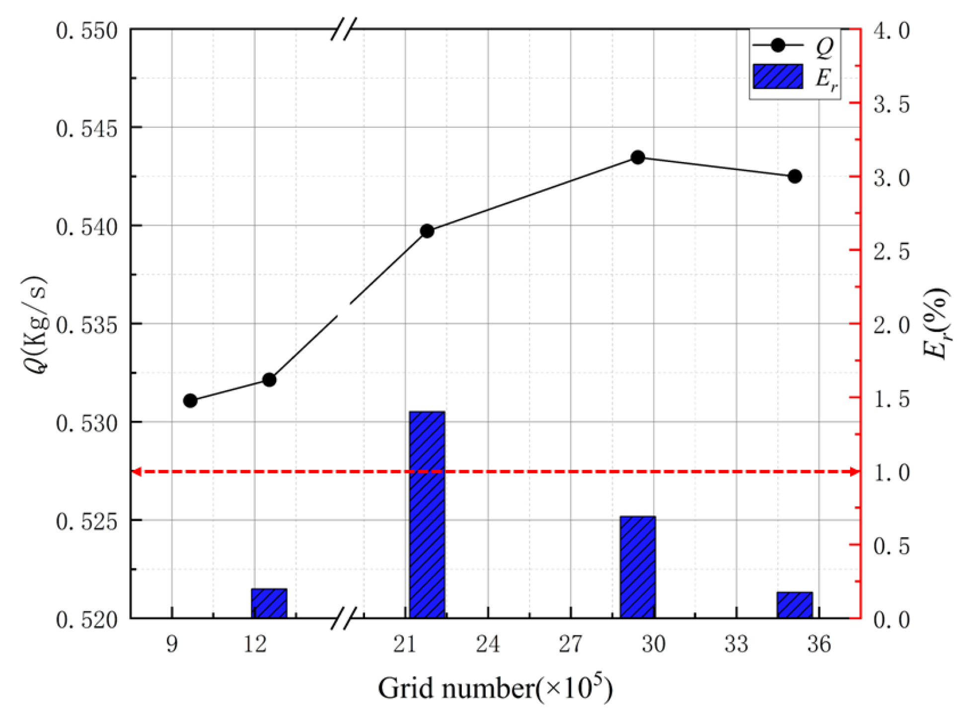
The utilization of a large quantity of high-quality grids ensures that the computational results are both precise and accurate. However, the large number of grids will consume a lot of computation time. To strike an optimal balance between computational efficiency and accuracy, it is imperative to establish the grid count through grid independence verification (GIV) prior to advancing with further calculations. The purpose of GIV is to determine the optimal number of grids that achieve adequate computational accuracy without unnecessarily consuming computational resources. Therefore, the structured grids have been carried out from 9.7 × 10⁵ to 3.5 × 10⁶ elements. The result leakage Q and corresponding relative error Er for GIV are shown in Figure 4.
As shown in Figure 4, the number of grids has a significant effect on leakage when the number of grids is small. Nevertheless, when the number of grids is greater than 2.2 × 10⁶, grid refinement exhibits marginal influence on enhancing calculation accuracy. At a grid number of 2.2 × 10⁶, the rate of change in leakage is below 1%, and the leakage exhibits minimal variation with the incremental enlargement of the grid size. Consequently, the optimal number of grids for further calculations is 2.2 × 10⁶.

3.2. Validation of Numerical Method

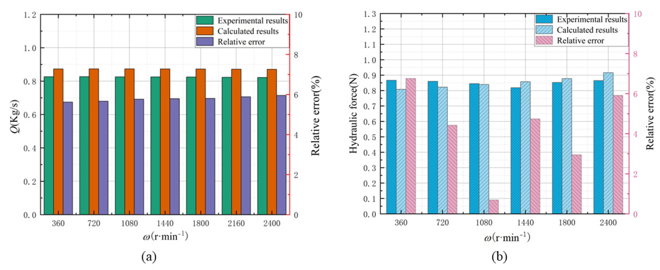
To verify the accuracy and reliability of the present numerical method, the simulation results are compared with the experimental results of the labyrinth seal with a typical herringbone-grooved rotor proposed by Zhai [31]. The test rig includes test apparatus, driving devices, whirling devices and transmissions, which can measure the leakage and hydraulic forces within the herringbone-grooved seal under different operating conditions. The selected data for comparison correspond to a configuration where the upstream spiral section, the intermediate smooth section and the downstream spiral section measure 12 mm, 4 mm and 12 mm in length, respectively. In the validation, the pressure drop is set at 0.142 MPa, and the rotation speeds range from 360 rpm to 2400 rpm. The corresponding verification results are shown in Figure 5.
Figure 5 presents the validation outcomes, comparing the simulated and experimental results for hydraulic force and leakage at different rotational speeds. It is noted that the calculated results are almost the same as the experimental results when the rotating speed ranges from 360 r/min to 2160 r/min. The maximum error between calculated and experimental results for leakage was only 5.95%. To ensure accurate calculation of the dynamic characteristics, the hydraulic force data are also shown in Figure 5b in comparison with the experimental data. The experimental results had errors ranging from 0.69% to 5.92%, which confirms the commendable accuracy and reliability of the numerical method used in this study.

4. Results and Discussion

In order to obtain the static characteristics of the SET structure, this paper calculates the leakage Q under different pressure drops, axial offsets of rotor teeth, rotating speeds and seal clearances. In addition, the dynamic coefficients and whirl-frequency ratio are also studied. To compare the quality of the sealing performance, the mass flow rate is viewed as a measure in that incompressible fluid is used as the sealing medium.

4.1. The Static Characteristics of the SET Structure

4.1.1. The Influences of Axial Offset and Pressure Drop on Leakage Performance

Under specific operating conditions, pressure pulsations within the pump structure may induce vibrations in the impeller, resulting in axial offset at the seal port ring and consequently affecting the leakage performance. Accordingly, the paper investigates the relationship between the axial offset of rotor teeth and leakage, with an emphasis on the direction of flow, where the axial offset of rotor teeth is considered positive. Considering that the pressure drop is the main factor affecting the size of leakage [32,33], Figure 6 presents the influence of both the axial offset of the rotor and pressure drop on leakage, with Δp escalating from 0.2 MPa to 0.8 MPa and Δz varying from −1 mm to 1 mm. The analysis reveals that an increase in pressure drop leads to heightened leakage for a constant axial offset of the rotor. In addition, for a constant pressure drop, sealing performance is optimal when there is no axial offset of the rotor, i.e., Δz is 0. The presence of axial offset of the rotor can lead to increased leakage. The magnitude of the offset directly correlates with the amount of leakage.
To verify the contribution of the novel labyrinth seal structure to the improved sealing performance, the leakage Q of the labyrinth seal structure with the SET structure and the smooth annular seal under different pressure drops are compared. As shown in Figure 6, the novel SET structure provides a better sealing effect. Compared to the smooth annular seal, the SET seal demonstrates a significant reduction in leakage of up to about 30%; the results clearly illustrate the superior sealing performance of the novel structure. Additionally, the novel SET structure is less sensitive to pressure drop than a smooth annular seal.
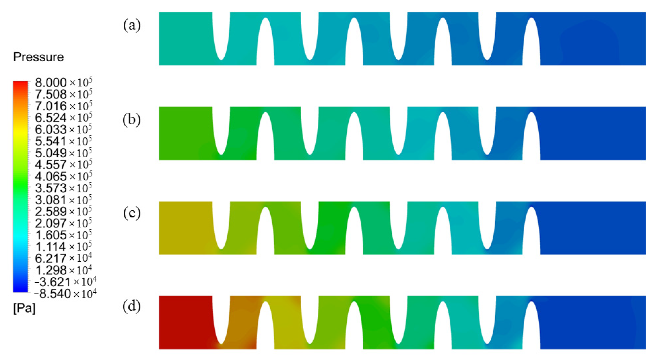
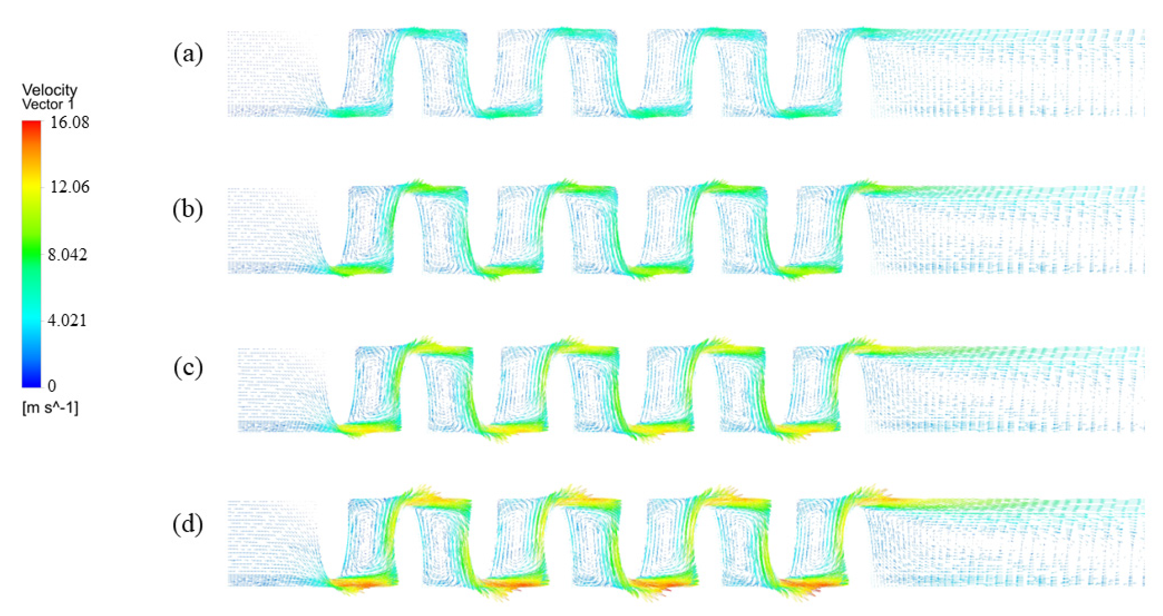
To further explore the mechanisms underlying the observed reduction in leakage across varying pressure drops, an analysis was performed focusing on the velocity streamlines and pressure contours for different pressure drops. As shown in Figure 7, maintaining a constant axial offset of the rotor reveals that an increase in pressure drop leads to a corresponding increase in both the pressure gradient and the flow rate through the seal. The energy of the fluid pressure is mainly dissipated in the cavity through the throttle teeth. The internal fluid works together with the vortex inside the cavity and exchanges energy with each other when the internal fluid passes through the sealing tooth gap, which makes the energy of the fluid dissipate in large quantities. The flow path of the high-velocity stream is illustrated in Figure 8. As the pressure drop increases, the amount of high-velocity fluid in the cavity also increases, which inhibits the formation of dissipative vortices.

4.1.2. The Influences of Seal Clearance and Rotating Speed on Leakage Performance

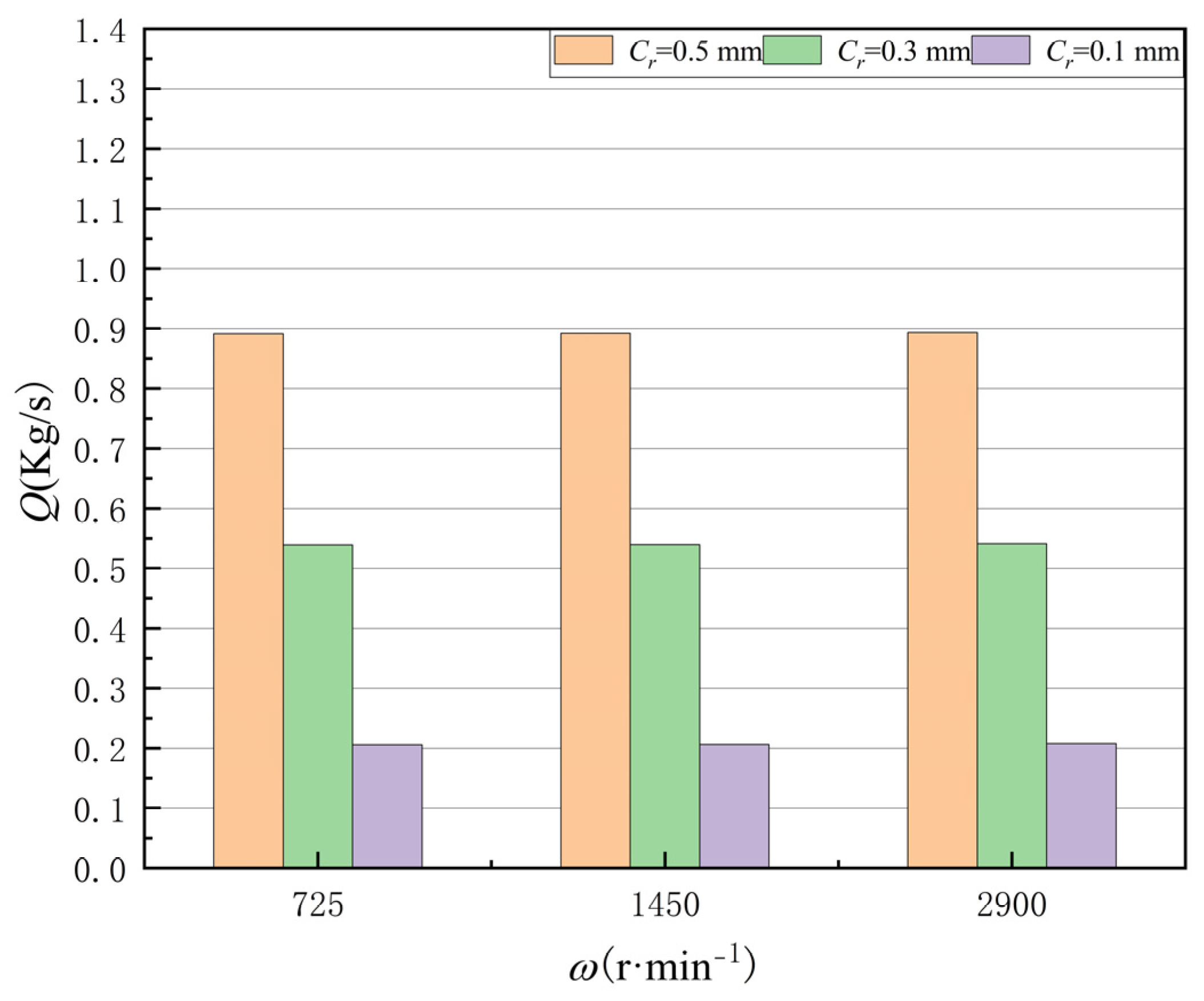
Seal clearance is a crucial factor in preventing leakage. This paper explores the effects of different seal clearances and rotational speeds on the leakage performance of the SET structures. As can be seen in Figure 9, the findings illustrate a direct relationship between seal clearance and leakage: as the seal clearance widens, leakage correspondingly escalates. It is worth noting that diminishing the seal clearance exerts a pronounced influence on the magnitude of leakage, which also indicates that the seal clearance is an extremely important parameter in the sealing structure. Moreover, the analysis reveals that variations in rotating speed only marginally affect the leakage of SET structures, suggesting that rotating speed exerts a limited influence on the seal’s static characteristics. This observation implies that, within the studied range, the SET structure’s leakage performance is more sensitively dictated by seal clearance than by rotating speed.
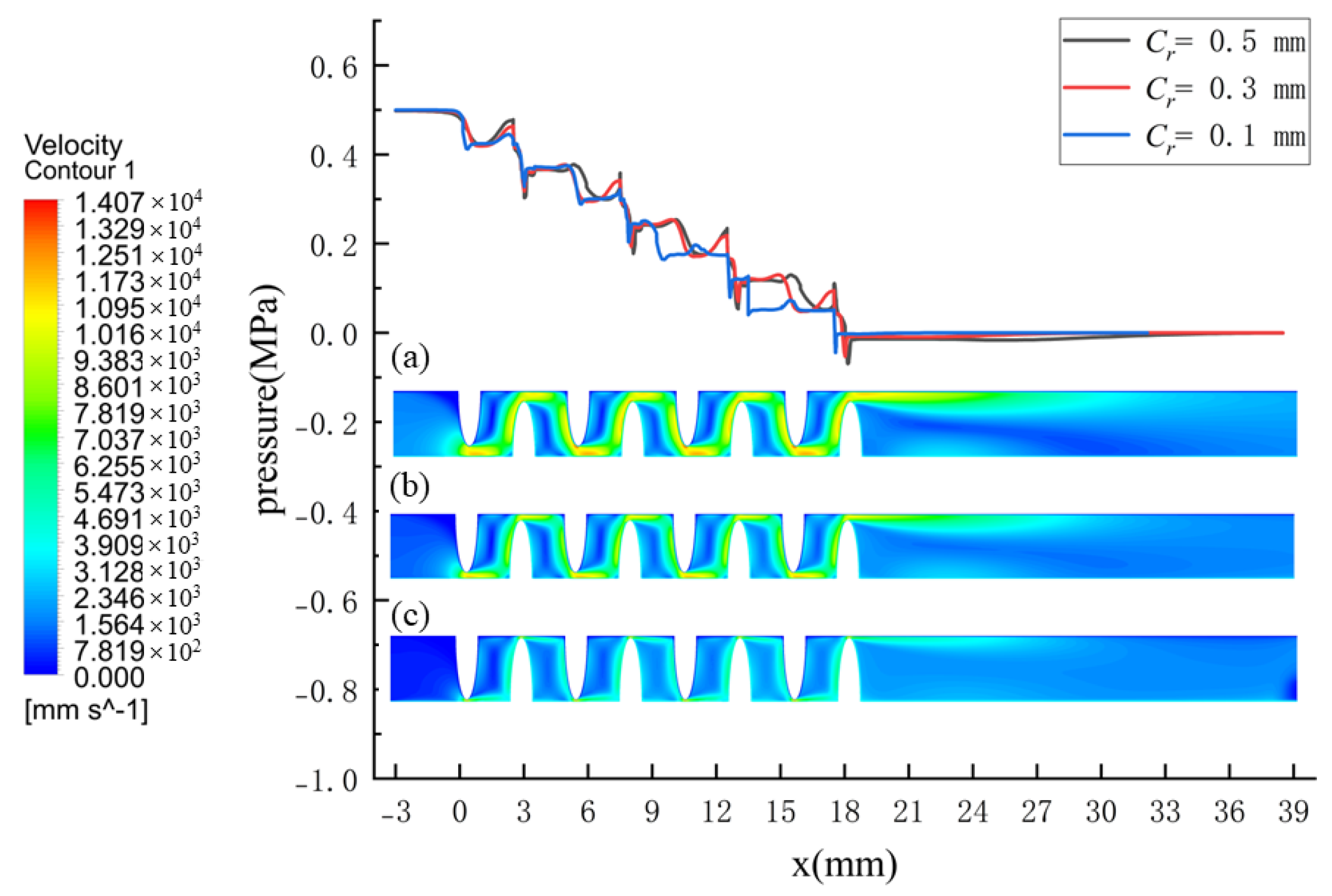
The pressure distribution and velocity contours along the wall surface of the rotor at different seal clearances are shown in Figure 10. A rapid decrease in fluid pressure is observed as it passes through the constricted regions of the throttle teeth, followed by a subsequent recovery within the cavity. The effectiveness of fluid pressure recovery decreases with the reduction in clearance. This iterative process continues until the final reduction in clearance aligns the outlet fluid pressure more closely with the back pressure, resulting in a reduction in leakage.

4.2. The Dynamic Characteristics of the SET Structure

When the rotor is disturbed by a small displacement and speed, the relationship between the fluid-induced force acting on the rotor and the motion parameters can be linearly expressed as [31]:
F x F y = M m M c M c M m x ¨ y ¨ + C m C c C c C m x ˙ y ˙ + K m K c K c K m x y
where Fx and Fy are the components of acting force in the x- and y- directions, respectively. Mm and Mc are the direct mass coefficient and cross-coupled mass coefficient, respectively. Cm and Cc are the direct damping coefficient and cross-coupled damping coefficient, respectively. Km and Kc are the direct stiffness coefficient and cross-coupled stiffness coefficient, respectively.
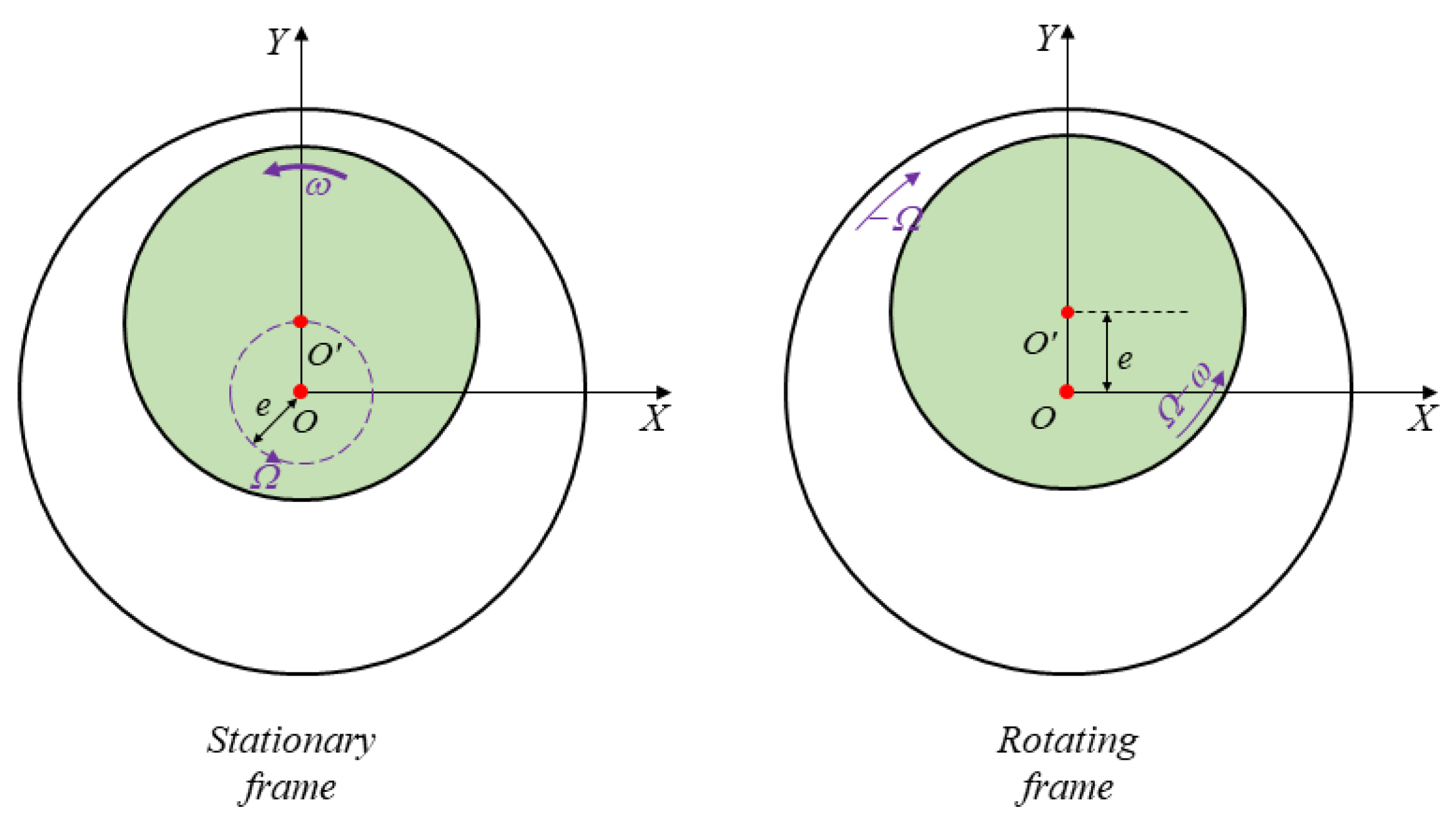
To analyze the rotor-seal system motion from a stationary frame, it is noted that the rotor rotates at speed ω and also revolves around the stator center at speed Ω, presenting a transient problem that involves moving grids. To circumvent the need for transient analysis and mesh movement, a rotating frame approach is adopted for evaluating the dynamic characteristics of the SET structure, as depicted in Figure 11. Within this framework, the rotor spins at a relative speed of ωΩ, while the stator rotates at speed Ω in the opposing direction, transforming the transient issue into a steady-state one, hence obviating grid displacement concerns.
Moreover, the dynamic coefficients can be solved by Fr and Fτ, which can be integrated as follows:
F r = 0 L 0 2 π p φ , z c o s φ R d φ d z
F τ = 0 L 0 2 π p φ , z s i n φ R d φ d z
where Fr and Fτ are the radial and tangential components of the exciting force on the rotor, respectively, p( φ , z) is the pressure on the rotor surface, φ is the radian in the circumferential direction, z is the axial direction, and R is the radius of the rotor. Once the horizontal and vertical components of the exciting force are solved by numerical calculation, the surface pressure can be obtained. The circumferential and axial quadratic integrals can further be applied to obtain the two-direction components. The rotor dynamics coefficient can be calculated using the following equation:
F r e = K m C c Ω + M m Ω 2 F τ e = K c C m Ω
In addition, five types of the ratio of whirling speed to rotating speed are selected to obtain the dynamic characteristics.

4.2.1. The Dynamic Characteristic Coefficients

Figure 12 presents the influences of axial offset and pressure drop on dynamic characteristic coefficients. The results show that pressure drop plays a significant role in the variation of dynamic characteristics. The direct damping coefficient Cm increases with an increase in pressure drop, while the other dynamic characteristic coefficients decrease as the pressure drop increases. In this simulation, the cross-coupled stiffness coefficient Kc exhibits negative values, which is consistent with the findings of Gu et al. [34], who observed a similar trend when the number of teeth of the labyrinth seal was less than a certain number. Furthermore, Kc decreases as inlet pressure increases; the results indicate that system stability is better for higher pressure differences. The dynamic coefficients show complex changes when the axial displacement is considered. The direct damping coefficient Cm is at its maximum when the axial offset ∆z is +1, while it increases when the axial offset ∆z is −1. As for the direct stiffness coefficient Km, it is minimized when the axial offset ∆z is +1.
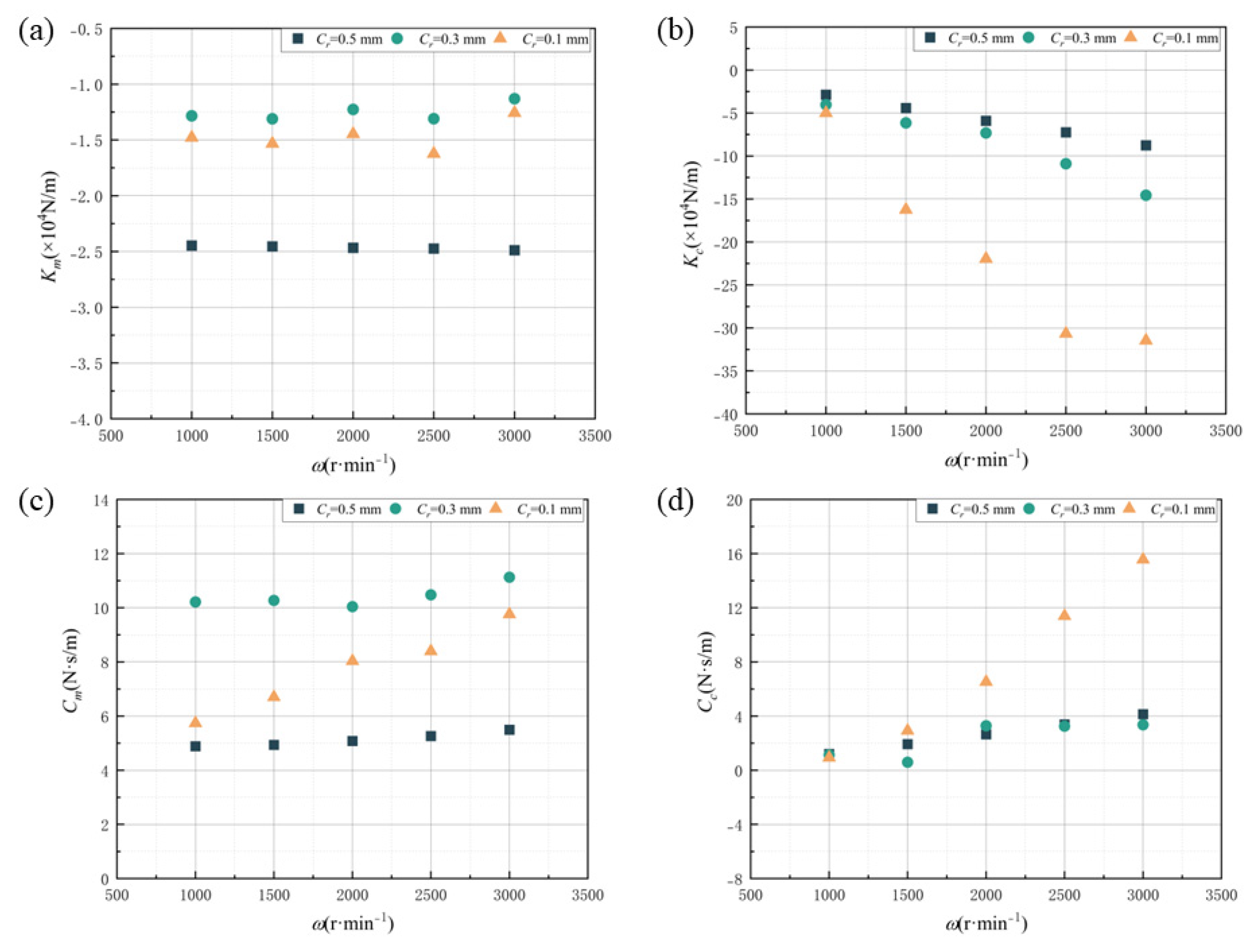
Figure 13 displays the impact of seal clearance and rotating speed on the dynamic characteristic coefficients of the SET structure. The direct stiffness coefficient Km is not significantly influenced by changes in rotating speed. In contrast, the cross-coupled stiffness coefficient Kc exhibits a pronounced negative correlation with rotating speed. For the damping coefficients, the sensitivity of both the direct damping coefficient Cm and the cross-coupled damping coefficient Cc to rotating speed varies with seal clearance. The damping coefficients remain relatively constant when the rotating speed changes from 1000 r/min to 3000 r/min at Cr = 0.5 mm. However, for smaller seal clearance Cr = 0.1 mm, both Cm and Cc exhibit an increasing trend with rotating speed, implying that the damping effect becomes more pronounced at higher speeds in small clearance for the SET structure.

4.2.2. The Stability Performance of the SET Structure

The cross-coupled stiffness coefficient Kc and the direct damping coefficient Cm are crucial as they directly impact the stability of the seal structure [35]. Tangential forces affect the cross-coupled stiffness coefficient Kc, which can cause instability in the rotor system. The direct damping coefficient Cm reflects the ability to suppress severe vibrations. The stability energy of the seal can be estimated from the whirl-frequency ratio f, defined as [36]:
f = K c C m ω
( f > 1 ) unstable ( 0 < f 1 ) stable ( f < 0 ) stable ,   if   f ( C > 0 , k < 0 )
Considering the unique characteristics of the SET structure, which include the negative cross-coupled stiffness coefficient Kc and positive direct damping coefficient Cm, an alternative criterion has been proposed to more accurately quantify the structure’s stability. This criterion is the quantized whirl-frequency ratio fc, whose magnitude is directly proportional to stability. The formula for calculating the quantized whirl-frequency ratio is defined as follows:
f c = C m ω K c
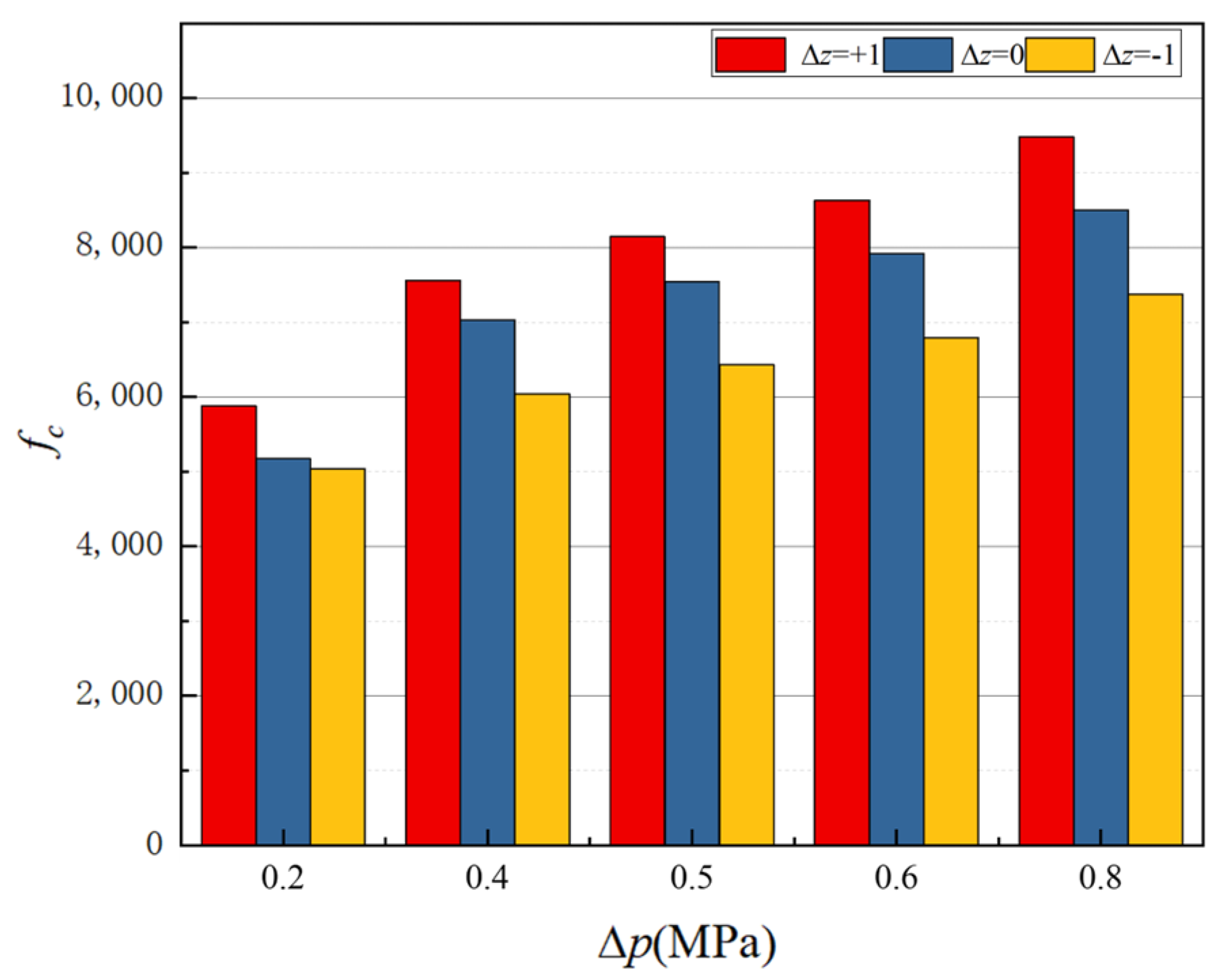
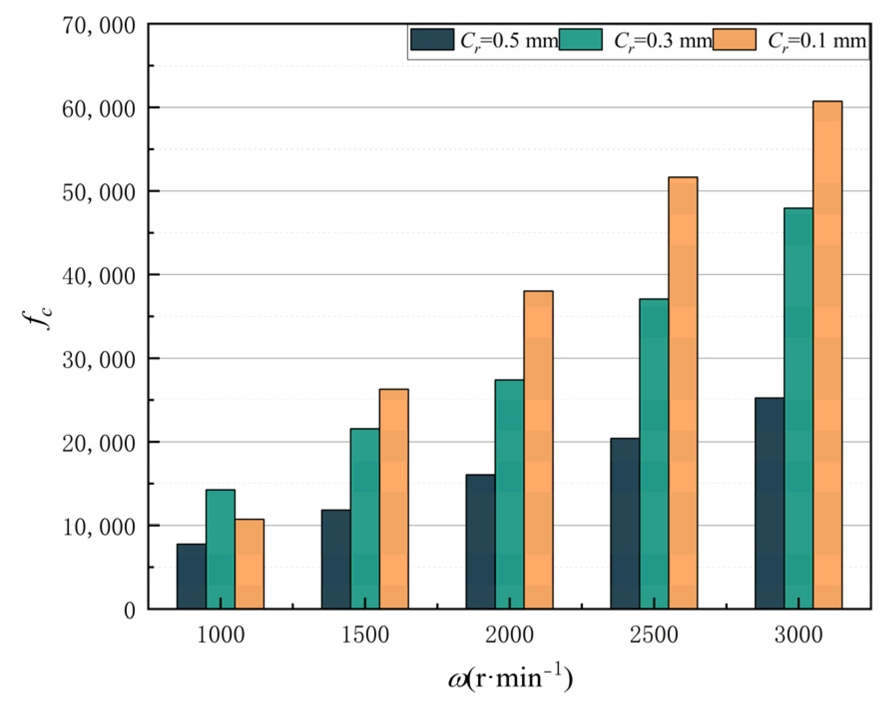
The effects of axial offset on the quantized whirl-frequency ratio at different pressure drops are shown in Figure 14. It is evident that the quantized whirl-frequency ratio fc increases as the pressure drop increases, indicating that the SET structure is more stable under a high pressure drop. Furthermore, the stability of the SET structure is greater when there is an axial offset of +1 compared to a structure with no offset and an axial offset of −1. This could be attributed to the fact that the axial offset reduces the cavity size between the rotor teeth and the stator teeth, which enhances the flow effect. When the axial displacement is positive, the high velocity flow in the small cavity moves towards the rotor center, causing a shift of the rotor center towards the static center, ultimately increasing the structure’s stability. Figure 15 shows the effects of seal clearance on the quantized whirl-frequency ratio at different rotating speeds. The higher quantized whirl-frequency ratio at 3000 r/min implies that the high rotating speed is good for the structure’s stability. The smaller the clearance, the higher the quantized whirl-frequency ratio at the same rotating speed in addition to the 1000 r/min.

5. Conclusions

In this paper, a novel labyrinth seal with SET structure is proposed, and its sealing performance is calculated and analyzed to minimize leakage and improve stability. The numerical results are compared with the experimental results. In addition, the effects of pressure drop, axial offset of rotor teeth, rotating speed and seal clearance on leakage and dynamic coefficients have also been studied. Meanwhile, the system stability for labyrinth seals with SET structure is further studied. The main conclusions are as follows.
(1) The numerical results for labyrinth seals with SET structure exhibit good accuracy and reliability. The maximum relative error between the numerical and experimental results obtained by simulation does not exceed 6%.
(2) Pressure drop and leakage rate are positively correlated, and the optimal sealing performance occurs at zero axial offset of the rotor (Δz = 0). The presence of any axial offset exacerbates leakage. The fluid pressure rapidly drops as it passes through the throttling teeth when the clearance decreases, followed by a recovery within the cavity.
(3) The direct damping coefficient Cm increases with the increased pressure drop while other dynamic coefficients decrease. The rotating speed has a limited effect on the damping coefficients when the seal clearances are 0.3 mm and 0.5 mm. Additionally, Cm peaks at an axial offset of +1, where the direct stiffness coefficient Km also reaches its minimum.
(4) The stability of the SET structure is notably enhanced at an axial offset of +1 compared to configurations with no offset or a negative axial offset. This relationship is supported by the positive correlation between the quantized whirl-frequency ratio and pressure drop, which suggests that the stability can be enhanced at higher pressure drop and specific axial displacement.

Author Contributions

Conceptualization, S.Y., Z.Y. and W.Z; methodology, S.Y. and W.Z.; software, H.S.; validation, S.Y., D.W. and H.S.; formal analysis, S.Y. and H.S.; investigation, D.W.; resources, S.Y. and Z.Y.; data curation, D.W.; writing—original draft preparation, S.Y. and H.S.; writing—review and editing, W.Z.; visualization, S.Y. and H.S.; supervision, Z.Y.; project administration, Z.Y. and W.Z.; funding acquisition, W.Z. All authors have read and agreed to the published version of the manuscript.

Funding

The research was funded by the Project funded by the China Postdoctoral Science Foundation (Grant No. 2018M642177).

Data Availability Statement

Data is contained within the article.

Conflicts of Interest

Authors Shebin Yan and Dezhao Wang were employed by the company AECC Guizhou Honglin Aero-Engine Control Technology Co., Ltd. The remaining authors declare that the research was conducted in the absence of any commercial or financial relationships that could be construed as a potential conflict of interest.

Nomenclature

LSeal length (mm)
CrClearance (mm)
HHeight of rotor tooth (mm)
B1Tooth width (mm)
B2Cavity width (mm)
ZTooth number
LgPitch between rotor teeth and static teeth (mm)
DRotor diameter (mm)
QLeakage (kg/s)
ΔpPressure drop (MPa)
Ω Whirling speed (rpm)
ω Rotating speed (rpm)
Fx, FySeal reaction force in x and y axis (N)
Fr, FτSeal reaction force in radial and tangential direction (N)
KmDirect stiffness coefficient (N/m)
KcCross-coupled stiffness coefficient (N/m)
CmDirect damping coefficient (N·s/m)
CcCross-coupled damping coefficient (N·s/m)
MmDirect added mass (kg)
McCross-coupled added mass (kg)
fWhirl frequency ratio
fcQuantized whirl-frequency ratio
ΔzStatic tooth offset(mm)

References

  1. Li, Q.; Li, S.; Wu, P.; Huang, B.; Wu, D. Investigation on Reduction of Pressure Fluctuation for a Double-Suction Centrifugal Pump. Chin. J. Mech. Eng. 2021, 34, 12. [Google Scholar] [CrossRef]
  2. Wu, C.; Li, Q.; Zheng, F.; Wu, P.; Yang, S.; Ye, H.; Huang, B.; Wu, D. Improve of Unsteady Pressure Pulsation Based on Jet–Wake Suppression for a Low Specific Centrifugal Pump. J. Fluids Eng. 2021, 143, 111202. [Google Scholar] [CrossRef]
  3. Zahorulko, A. Experimental and CFD Analysis of Static and Dynamic Rotor Stabilities in Three-Annular Seals. Tribol. Int. 2023, 185, 108566. [Google Scholar] [CrossRef]
  4. Zhou, W.; Yu, D.; Wang, Y.; Shi, J.; Gan, B. Research on the Fluid-Induced Excitation Characteristics of the Centrifugal Pump Considering the Compound Whirl Effect. Facta Univ. Ser. Mech. Eng. 2023, 21, 223–238. [Google Scholar] [CrossRef]
  5. Chupp, R.E.; Hendricks, R.C.; Lattime, S.B.; Steinetz, B.M. Sealing in Turbomachinery. J. Propul. Power 2006, 22, 313–349. [Google Scholar] [CrossRef]
  6. Wang, L.; Huang, F.; Luo, Y.; Chen, C. Research on the Dynamic Characteristics of Crack Damage of a Seal-Rotor System. Nonlinear Dyn. 2022, 109, 1851–1876. [Google Scholar] [CrossRef]
  7. Kim, T.S.; Cha, K.S. Comparative Analysis of the Influence of Labyrinth Seal Configuration on Leakage Behavior. J. Mech. Sci. Technol. 2009, 23, 2830–2838. [Google Scholar] [CrossRef]
  8. Zhang, W.; Ma, K.; Cao, H.; Wang, T.; Yang, J.; Li, C. The Static Instability Characteristics of Labyrinth Seals: Experiments and Computational Fluid Dynamics Verification. J. Vib. Acoust. 2020, 142, 041005. [Google Scholar] [CrossRef]
  9. Qin, H.; Lu, D.; Zhong, D.; Wang, Y.; Song, Y. Experimental and Numerical Investigation for the Geometrical Parameters Effect on the Labyrinth-Seal Flow Characteristics of Fast Reactor Fuel Assembly. Ann. Nucl. Energy 2020, 135, 106964. [Google Scholar] [CrossRef]
  10. Zhang, X.; Jiang, J.; Peng, X.; Zhao, W.; Li, J. Leakage Reduction by Optimization of Hole-Pattern Damping Seal with Inclined Hole Cavity. Int. J. Heat Mass Transf. 2021, 169, 120924. [Google Scholar] [CrossRef]
  11. Zhou, W.; Zhao, Z.; Wang, Y.; Shi, J.; Gan, B.; Li, B.; Qiu, N. Research on Leakage Performance and Dynamic Characteristics of a Novel Labyrinth Seal with Staggered Helical Teeth Structure. Alex. Eng. J. 2021, 60, 3177–3187. [Google Scholar] [CrossRef]
  12. Hirs, G.G. A Bulk-Flow Theory for Turbulence in Lubricant Films. J. Lubr. Technol. 1973, 95, 137–145. [Google Scholar] [CrossRef]
  13. Childs, D.W.; Scharrer, J.K. Theory Versus Experiment for the Rotordynamic Coefficient of Labyrinth Gas Seals: Part II—A Comparison to Experiment. J. Vib. Acoust. 1988, 110, 281–287. [Google Scholar] [CrossRef]
  14. Eser, D.; Kazakia, J.Y. Air Flow in Cavities of Labyrinth Seals. Int. J. Eng. Sci. 1995, 33, 2309–2326. [Google Scholar] [CrossRef]
  15. Nordmann, R.; Dietzen, F.J.; Weiser, H.P. Calculation of Rotordynamic Coefficients and Leakage for Annular Gas Seals by Means of Finite Difference Techniques. J. Tribol. 1989, 111, 545–552. [Google Scholar] [CrossRef]
  16. Saber, E.; Abdou, K.M.; Afify, R. Effect of Shaft Eccentricity on Dynamic Characteristics for Different Geometries of Stationary Labyrinth Seals. Alex. Eng. J. 2020, 59, 61–75. [Google Scholar] [CrossRef]
  17. Zhang, X.; Jiao, Y.; Qu, X.; Zhou, J.; Zhao, Z. Rotordynamic Analysis and Leakage Performance Study of a Hole Diaphragm Labyrinth Seal Using the CFD Method. Alex. Eng. J. 2022, 61, 9921–9928. [Google Scholar] [CrossRef]
  18. Zhang, X.; Jiao, Y.; Du, H.; Huo, G.; Xu, Y.; Che, R. Transient Investigations of Teeth on Rotor and Teeth on Stator Modified Labyrinth Seals. Tribol. Int. 2024, 192, 109296. [Google Scholar] [CrossRef]
  19. Sun, D.; Wang, S.; Ai, Y.; Zhou, H.; Wang, K. Experimental Investigation of Rotordynamic Coefficients for the Labyrinth Seals with and without Shunt Injection. J. Vibroeng. 2015, 17, 4289–4300. [Google Scholar]
  20. Zhai, L.; Zhu, Z.; Zhang, Z.; Guo, J.; Cui, B. Theoretical Solutions for Dynamic Characteristics of Spiral-Grooved Liquid Seals. Tribol. Trans. 2019, 62, 22–33. [Google Scholar] [CrossRef]
  21. Zhai, L.; Zhenjie, Z.; Zhonghuang, C.; Jia, G. Dynamic Analysis of Liquid Annular Seals with Herringbone Grooves on the Rotor Based on the Perturbation Method. R. Soc. Open Sci. 2018, 5, 180101. [Google Scholar] [CrossRef] [PubMed]
  22. Zhang, Y.; Li, J.; Li, Z.; Yan, X. Effect of Bristle Pack Position on the Rotordynamic Characteristics of Brush-Labyrinth Seals at Various Operating Conditions. Chin. J. Aeronaut. 2020, 33, 1192–1205. [Google Scholar] [CrossRef]
  23. Wu, T.; San Andrés, L. Leakage and Dynamic Force Coefficients for Two Labyrinth Gas Seals: Teeth-on-Stator and Interlocking Teeth Configurations. A Computational Fluid Dynamics Approach to Their Performance. J. Eng. Gas Turb. Power 2019, 141, 042501. [Google Scholar] [CrossRef]
  24. Li, Z.; Li, J.; Feng, Z. Numerical Comparisons of Rotordynamic Characteristics for Three Types of Labyrinth Gas Seals with Inlet Preswirl. Proc. Inst. Mech. Eng. Part A J. Power Energy 2016, 230, 721–738. [Google Scholar] [CrossRef]
  25. Jia, X.; Zheng, Q.; Jiang, Y.; Zhang, H. Leakage and Rotordynamic Performance of T Type Labyrinth Seal. Aerosp. Sci. Technol. 2019, 88, 22–31. [Google Scholar] [CrossRef]
  26. Iwatsubo, T.; Sheng, B.C. Evaluation of Seal Effects on the Stability of Rotating Fluid Machinery. Int. J. Rotating Mach. 1995, 1, 145–152. [Google Scholar] [CrossRef]
  27. Jin, Y.; Zhang, D.; Wang, Z. Analysis of upper-end seal leakage of high-temperature molten salt pump based on VOF model. J. Drain. Irrig. Mach. Eng. 2020, 38, 1209–1214. (In Chinese) [Google Scholar]
  28. Zhang, X.; Xu, Y.; Zhang, S.; Che, R.; Chen, Z.; Jiao, Y. Improved Vibration Performance of a Nonlinear Rotor-Seal System with Modified Labyrinth Seals by an Interpolating Database Method. Tribol. Int. 2024, 191, 109170. [Google Scholar] [CrossRef]
  29. Zhang, M.; Yang, J. Spiral Flow Induced Destabilizing Force Analysis and Its Reduction with a Novel Helix-Comb Gas Seal. Aerosp. Sci. Technol. 2020, 105, 105997. [Google Scholar] [CrossRef]
  30. Xue, W.; Fang, Z.; Wang, T.; Li, Z.; Li, J. Rotordynamic Characteristics of a Novel Labyrinth Seal with Partition Walls and Helical Groove Teeth. Proc. Inst. Mech. Eng. Part A J. Power Energy 2024, 238, 515–529. [Google Scholar] [CrossRef]
  31. Zhai, L.; Wu, G.; Wei, X.; Qin, D.; Wang, L. Theoretical and Experimental Analysis for Leakage Rate and Dynamic Characteristics of Herringbone-Grooved Liquid Seals. Proc. Inst. Mech. Eng. Part J J. Eng. Tribol. 2015, 229, 849–860. [Google Scholar] [CrossRef]
  32. Li, J.; Obi, S.; Feng, Z. The Effects of Clearance Sizes on Labyrinth Brush Seal Leakage Performance Using a Reynolds-Averaged Navier—Stokes Solver and Non-Darcian Porous Medium Model. Proc. Inst. Mech. Eng. Part A J. Power Energy 2009, 223, 953–964. [Google Scholar] [CrossRef]
  33. Lin, Z.; Wang, X.; Yuan, X.; Shibukawa, N.; Noguchi, T. Investigation and Improvement of the Staggered Labyrinth Seal. Chin. J. Mech. Eng. 2015, 28, 402–408. [Google Scholar] [CrossRef]
  34. Gu, Q.; Zhang, W.; Chen, L.; Ma, K.; Li, C.; Yang, J. Study on the Critical Stable State of the Labyrinth Seal. J. Mech. Eng. 2020, 56, 144–151. (In Chinese) [Google Scholar]
  35. Pugachev, A.O. CFD Optimization of Liquid Annular Seals for Leakage and Rotordynamics Improvement. In Turbo Expo: Power for Land, Sea, and Air; ASME: Orlando, FL, USA, 2009. [Google Scholar]
  36. Iwatsubo, T.; Ishimaru, H. Consideration of Whirl Frequency Ratio and Effective Damping Coefficient of Seal. J. Syst. Des. Dyn. 2010, 4, 177–188. [Google Scholar] [CrossRef]
Figure 1. The novel labyrinth seal with semi-elliptical tooth (SET) structure.
Lubricants 12 00169 g001
Figure 2. Radial profile and main parameters of semi-elliptical tooth (SET) structure.
Lubricants 12 00169 g002
Figure 3. The structure grid of elliptical structures.
Lubricants 12 00169 g003
Figure 4. The leakage and relative error for grid independence verification (GIV).
Lubricants 12 00169 g004
Figure 5. The verification results of hydraulic force and leakage for different rotating speeds: (a) hydraulic force, (b) leakage.
Lubricants 12 00169 g005
Figure 6. The influence of axial offset and pressure drop on leakage performance.
Lubricants 12 00169 g006
Figure 7. The pressure contour at ∆z = 0 mm for different pressure drops: (a) 0.2 MPa, (b) 0.4 MPa, (c) 0.6 MPa, (d) 0.8 MPa.
Lubricants 12 00169 g007
Figure 8. The velocity streamline at ∆z = 0 mm for different pressure drops: (a) 0.2 MPa, (b) 0.4 MPa, (c) 0.6 MPa, (d) 0.8 MPa.
Lubricants 12 00169 g008
Figure 9. The influence of seal clearance and rotating speed on leakage performance.
Lubricants 12 00169 g009
Figure 10. Pressure distribution and velocity contours along the wall surface of the rotor at different seal clearances: (a) Cr = 0.5 mm, (b) Cr = 0.3 mm, (c) Cr = 0.1 mm.
Lubricants 12 00169 g010
Figure 11. Frame transfer from stationary to rotating.
Lubricants 12 00169 g011
Figure 12. Dynamic coefficients for different pressure drops and axial offsets: (a) direct stiffness Km, (b) cross-coupled stiffness Kc, (c) direct damping Cm and (d) cross-coupled damping Cc.
Lubricants 12 00169 g012
Figure 13. Dynamic coefficients for different seal clearances and rotating speeds: (a) direct stiffness Km, (b) cross-coupled stiffness Kc, (c) direct damping Cm and (d) cross-coupled damping Cc.
Lubricants 12 00169 g013
Figure 14. Effect of axial offsets on quantized whirl-frequency ratio for different pressure drops.
Lubricants 12 00169 g014
Figure 15. Effect of seal clearances on quantized whirl-frequency ratio for different rotating speeds.
Lubricants 12 00169 g015
Table 1. The values of structural parameters.
ParametersL/mmCr/mmH/mmB1/mmB2/mmZLg/mmD/mm
Value41.50.32.71442.550
Table 2. Numerical details for the Computational Fluid Dynamics analyses.
Numerical ParametersSpecification
Inlet pressure0.2 MPa
Outlet pressure0 MPa
Turbulence modelStandard k-ε
Wall functionScalable
Discretization2nd order upwind scheme
Rotation speed1450 rpm
Disclaimer/Publisher’s Note: The statements, opinions and data contained in all publications are solely those of the individual author(s) and contributor(s) and not of MDPI and/or the editor(s). MDPI and/or the editor(s) disclaim responsibility for any injury to people or property resulting from any ideas, methods, instructions or products referred to in the content.