Article

Research on Loaded Contact Analysis and Tooth Wear Calculation Method of Cycloid–Pin Gear Reducer

1
School of Mechanical and Electronic Engineering, Henan University of Science and Technology, Luoyang 471003, China
2
School of Mechanical and Electronic Engineering, Shangqiu Polytechic, Shangqiu 476000, China
3
Ningbo Zhongda Leader Intelligent Transmission Co., Ltd., Ningbo 315000, China
*
Author to whom correspondence should be addressed.
Lubricants 2023, 11(10), 445; https://doi.org/10.3390/lubricants11100445
Submission received: 18 September 2023 / Revised: 29 September 2023 / Accepted: 7 October 2023 / Published: 13 October 2023
(This article belongs to the Special Issue Wear Mechanism Identification and State Prediction of Tribo-Parts)

Abstract

:
This study establishes the geometric model of cycloid–pin gear meshing transmission based on the multi-tooth meshing characteristics of the cycloid speed reducer. The calculation and analysis of meshing motion parameters of the cycloid speed reducer are carried out. An integrated calculation flow is presented for solving the question of the loaded tooth contact of the cycloid speed reducer by using the elimination clearance method of gradual contact and the quasi-Hertz contact simulation of the tooth surface under loads. The loaded transmission error is obtained, and both the number of pins participating in the meshing and the contact area of tooth surfaces are determined. Using the regression formula of the wear coefficient, the dynamic wear coefficient is quickly solved on the instantaneous contact line of the tooth surface. Thereby, the wear distribution law of two tooth surfaces appears. The results show that there is a singular point in the wear of the pin teeth, with a maximum wear of 100 μm, that seriously affects the meshing accuracy of the tooth surface and thus affects the accuracy and lifespan of the reducer.

1. Introduction

The precision maintenance and reliability of gear reducers are crucial to the operating performance of robots. At the same time, the manufacturing industry’s current development has put forward high requirements for high-precision robot reducers, the precision of tooth clearance and angle transmission is less than one arc cent, and the rated life is better than 10,000 h. Because of its multi-tooth meshing characteristics and complex structure, the mechanism of the impact of tooth surface wear on the life accuracy of a cycloid–pin gear reducer is not clear.
To improve the service life of the reducer, the wear distribution of the tooth surface and the influence of tooth modification parameters on its working performance have been researched.
Xu et al. [1,2,3] proposed a dynamic analysis method for the multi-tooth meshing contact of a cycloid speed reducer considering the influence of crank bearing to accurately predict the number of pin teeth engaged in meshing and the characteristics of the multi-point contact of crank bearing when considering the assembly clearance. According to the features of the over-constrained structure of the RV reducer, Yang [4] established and verified the relationship between the original error and the transmission accuracy. Li et al. [5] presented an unloaded and loaded tooth contact analysis model of the cycloid–pin gear. They predicted the load on each part of the reducer with clearance and eccentric error. Sun [6] designed a new structure China bearing reducer and proposed a parabolic modification to improve transmission accuracy through tooth contact analysis. Based on the minimum energy principle analysis method, Li [7] obtained the load characteristics in line with reality and determined the number of pin teeth involved in meshing.
According to the meshing principle of the tooth surface, Song and Li [8,9] established the model of the sliding speed and sliding coefficient of the meshing point and determined the relevant parameters from the point of view of improving anti-gluing ability and transmission efficiency. Yi [10] derived the general formula for calculating the slip rate using the conjugate contact curve of the tooth profile and concluded that the slip rate of the line–face meshing pair was significantly lower than that of the face–face meshing pair. Wang [11] investigated the change in the sliding speed of the meshing point in the cycloid–pin wheel transmission process and compared the roller’s effect on sliding loss. Ji [12] analyzed the meshing process of the cycloid speed reducer, discussed the influence of the motion state of the pin on the slip coefficient, and then evaluated the wear of the cycloid gear tooth profile. Xu [13] studied the slip ratio of the new cycloid gear transmission and analyzed the influence of transmission parameters on the slip ratio. Zhang [14] proposed a new method to calculate the parameters of the quasi-hyperbolic pitch cone, which simplified the calculation process and used two kinds of characteristic functions to calculate the point slip characteristics of the meshing tooth surface.
The wear changes the tooth surface and load distribution, increases the transmission error, reduces the transmission precision, and causes vibration and noise, which will seriously induce or accelerate gear failure [15,16]. The main wear form of gears is adhesive wear [17]. The Archard wear model agrees well with the observed results [18]. Anderson [19,20] extended Archard’s wear formula and proposed a single-point observation method to calculate the wear of involute spur and helical gears. Flodin [21] estimated the wear of helical gears using the slicing method, which simplified the helical gears into multiple thin-slice spur gears stacked along the axis and rotated in turn at small angles. Janakiraman [22] determined the wear coefficient under different operations and surface conditions through experiments and gave a regression formula to estimate the wear coefficient. Considering the effect of oil film thickness on the wear of tooth profile, refs. [23,24] proposed an approximate analytical model of the wear coefficient. Terauchi and Feng [25,26] calculated the change in gear meshing stiffness with uniform wear, dynamic cumulative wear, micro-pitting, and macroscopic pitting.
Ning [27] proposed the coupling calculation model of adhesive wear and EHL lubrication. Utilizing substituting the wear amount into the dynamic model as the backlash, he calculated the dynamic meshing force and wear amount under different meshing times. Shen [28] adopted an analytical modeling method to quantitatively study the influence rule of gear wear on time-varying meshing stiffness and dynamic parameters of unload static transmission error. Su [29] established the wear calculation method of a cycloid–pinwheel using the discrete approach of a tooth profile. Zhang [30] discussed the influence of wear dynamic evolution on the degradation of the core transmission performance, transmission error, and meshing torsional stiffness of an RV reducer. Reference [31] calculated the influence of input speed and torque on efficiency under four different loads. Reference [32] analyzed the influence of damping on transmission efficiency. Zhou and Wang [33,34,35] established an adhesive wear model of helical and double-helical gears in line contact hybrid EHL lubrication. They proposed a wear life prediction model to evaluate their wear resistance.
Much research has focused on the friction and wear of simple tooth profiles. However, there are few studies on the wear of cycloid–pin gear transmission and few on the impact of tooth surface wear on the accuracy and life of the transmission system. Therefore, it is necessary to study the loaded contact analysis of the cycloid speed reducer, the roll–slip mechanism of the cycloid–pin gear, and the wear evolution of the two tooth surfaces to solve the problems of poor accuracy retention and a short service life. Therefore, this paper establishes the bearing contact analysis model of a cycloid–pin gear and proposes the eliminating method to solve the problem of multi-tooth contact. Using the empirical regression formula of wear coefficient, the instantaneous wear coefficient of the tooth contact line is determined, avoiding the problem of low efficiency in determining wear coefficient through the equivalent test. The wear distribution of the two tooth surfaces in the load-bearing process is analyzed based on the classical wear model. The influence of the movement state of the needle teeth on the wear distribution of the two tooth surfaces is compared, and the influence mechanism of tooth surface wear on the life precision of the reducer is further determined, which lays a foundation for the subsequent complete life cycle design.

2. Construction of Cycloid Gear Tooth Profile Equation

In the process of cycloid–pin gear transmission, the cycloid gear both revolution and rotation. According to the principle of relative motion, giving the whole mechanism an angular speed equal to the crankshaft speed and opposite to the direction ω H , the relative motion relationship between the cycloid gear and the pin gear remains unchanged, and the whole mechanism is transformed from a planetary mechanism to a fixed-axis mechanism. In the conversion mechanism, the cycloid gear and the pin gear are internally engaged transmissions.
As shown in Figure 1, s f ( x f y f z f ) is fixed to the frame in a fixed coordinate system, and o f is the coordinate origin; s 1 x 1 y 1 z 1 and s 2 ( x 2 y 2 z 2 ) are fixedly connected with the pin gear and cycloid gear, respectively, which is the dynamic coordinate system; o 1 and o 2 are the origin of the corresponding coordinate system; o 1 coincides with o f ; the distance o 1 o 2 is the eccentricity e; point M is the meshing contact point; θ is the angle parameter of M on the pin tooth; φ 1 and φ 2 are the angles of the pin gear and cycloid gear relative to the rotary arm o 1 o 2 .
The formula of the transmission ratio of a fixed-axle gear train is
i 12 = ω 1 ω 2 = φ 1 φ 2 = z c z p
where z c and z p are the numbers of teeth of the cycloid gear and pin gear, respectively.
The position vector of the pin tooth profile in the coordinate system s 1 is
r 1 θ = r rp sin θ r p r rp cos θ 1
where r p is the radius of the distribution circle of the pin tooth, and r rp is the radius of the pin tooth.
After coordinate transformation, the theoretical tooth profile of the cycloid gear in the coordinate system s 2 can be expressed as
r 2 θ , φ 1 = M 2 f φ 2 M f 1 φ 1 r 1 θ = r p sin φ 1 z c r rp sin θ φ 1 z c + e sin z p · φ 1 z c r p cos φ 1 z c r rp cos θ φ 1 z c e cos z p · φ 1 z c 1
where K 1 = e · z p r p ,   θ = tan 1 K 1 sin φ 1 1 K 1 cos φ 1 , and M2f and Mf1 are coordinate transformation matrices. Then, φ 1 = ( 0,2 π ) , the single tooth profile of the cycloid gear is derived by the enveloping method, where φ 1 = z c · α , α = ( 0,2 π ) , and the equation of the whole tooth profile of the cycloid gear is obtained as follows:
r 2 α = r p sin α r rp sin θ α + e sin z p · α r p cos α r rp cos θ α e cos z p · α 1
To compensate for manufacturing and installation errors and ensure sufficient lubrication in a practical cycloid drive, it is necessary to modify the cycloid profile to produce the essential backlash. The tooth profile equation of the cycloidal gear is given, which includes equidistant modification, offset modification, and combination modification:
x 2 = ( r p + r p ) sin α ( r rp + r rp ) sin θ c α + e sin z p · α y 2 = ( r p + r p ) cos α ( r rp + r rp ) cos θ c α e cos z p · α
where θ c = tan 1 k 1 · sin ( z c · α ) 1 k 1 · cos ( z c · α ) , the lower subscript 1 represents the coordinate system s 1 , α is the tooth profile parameter of the cycloid gear, r p is the amount of displacement correction, r rp is the isometric modification amount, and k 1 = e · z p r p + r p .

3. Tooth Contact Analysis (TCA)

3.1. Unloaded TCA on Cycloid–Pin Gear

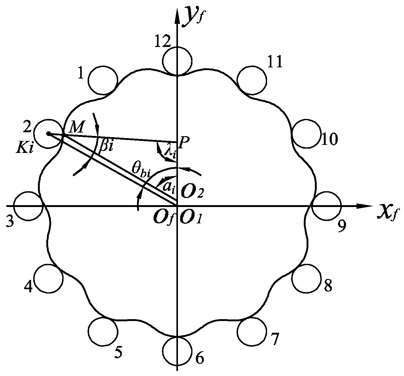
According to the engagement relationship of the cycloid–pin gear, the position relationship is shown in Figure 2, where α i is the tooth profile parameter of a point on the cycloid gear, β i is the tooth profile parameter of a point on the pin gear, θ b i is the angle between the center of the i pin tooth and the turning arms y f , and λ i is the angle between the common normal of the contact point M and the rotating arm y f . Because of tooth profile modification, the cycloid gear and pin gear do not mesh at the initial installation position, and there is a gap between each tooth pair. To make the cycloid–pin gear entangle and keep the cycloid gear motionless, turn the pin gear and calculate the rotation angle φ i of each pin tooth entering the meshing. γ min = min ( φ i ) is determined as the initial meshing angle, and the second pin tooth is the first contact with the cycloid gear profile.
The tooth surface vector r1 and unit normal vector n1 of the contact point M in the pin gear coordinate system s1 are represented, respectively, as
β i = r rp sin β i cos 2 π i z p sin 2 π i z p ( r rp cos β i + r p ) r rp sin β i sin 2 π i z p + cos 2 π i z p ( r rp cos β i + r p ) 1
n 1 β i = r 1 β i × K r 1 β i × K
The vector equation r2 and unit normal equation n2 of the contact point M on the modified cycloid tooth profile can be expressed in the coordinate system s2 as follows:
r 2 α i = ( r p + r p ) sin α i ( r rp + r rp ) sin θ c α i + e sin z p · α i ( r p + r p ) cos α i ( r rp + r rp ) cos θ c α i e cos z p · α i 1
n 2 β i = r 2 β i × K r 2 β i × K
According to the principle of coordinate transformation, the pin gear tooth surface vector r1 and unit normal vector n1 and the cycloid gear tooth surface vector r2 and unit normal vector n2 are, respectively, expressed in the fixed coordinate system sf through coordinate transformation:
r f 1 β i , φ 1 = M f 1 φ 1 r 1 β i n f 1 β i , φ 1 = M f 1 φ 1 n 1 β i
r f 2 α i , φ 2 = M f 2 φ 2 r 2 α i n f 2 α i , φ 12 = M f 2 φ 2 n 2 α i
M f 1 φ 1 = cos φ 1 sin φ 1   0 sin φ 1 cos φ 1   0 0   0   1
M f 2 φ 2 = cos φ 2 sin φ 2   0 sin φ 2 cos φ 2   e   0   0   1
For any instant, the geometric coordination condition of the contact between the cycloid gear and the pin gear is that the position vector is equal to the unit normal vector; that is,
r f 1 β i , φ 1 = r f 2 α i , φ 2   n f 1 β i , φ 1 = n f 2 α i , φ 2
According to the tooth profile equation, meshing motion, and geometric position relationship of the cycloid–pin gear, the position relationship of each meshing point is derived. For the convenience of the solution, the parameter value of each meshing point without modification is taken as the initial value of the iteration of the parameter value of each meshing point after modification, and the position shown in Figure 2 is taken as an example.
φ 2 0 = φ 1 · z p z c α i 0 = 2 π · i θ b i z c β i 0 = π λ i θ b i
where λ i = cos 1 ( r p · s 1 ) 2 + ( a · z p ) 2 r p 2 2 · ( r p · s 1 ) · ( a · z p ) , s 1 = 1 + k 1 2 2 k 1 cos θ b i , θ b i = 2 π i z p + φ 1 , 0 < θ b i < π is negative, and π < θ b i < 2 π is positive.
At the initial meshing position, let φ 1 = γ min ± φ , calculate a series of position parameters of meshing points, and obtain the corresponding cycloid gear rotation angle φ 2 at every instantaneous pin gear rotation angle φ 1 . The transmission error of cycloid–pinwheel is obtained.
In the process of continuous transmission, each pin tooth participates in meshing successively, so the geometric transmission error curve is a curve that changes periodically. Based on this, the transmission error curve of each pin tooth and the cycloid gear is expressed in the same coordinate system, and the comprehensive transmission error curve can be obtained.

3.2. Loaded Contact Analysis (LTCA) of Cycloid–Pin Gear

According to the meshing information and contact parameters obtained by the above unloaded TCA, the performance of load distribution can be further determined by the method of LTCA.
When not loaded, only a pair of teeth contact; the other teeth, due to the existence of backlash, do not engage. When the load Tc is applied, for any ith pair of teeth, if the relative displacement δi caused by the elastic deformation between the gear pairs exceeds its initial clearance di, the teeth participate in contact.
After modification, the tooth profile of the cycloid gear is no longer conjugated with that of the pin gear, the instantaneous transmission ratio changes with the angle of rotation, and node P changes with the angle of rotation. Therefore, the traditional calculation formula of force arm and backlash is no longer suitable for modified cycloid–pin gear transmission. The procedure for calculating the accurate contact force arm is given in reference [7].
L i α i = n 2 x · e + n 2 x · r 2 y n 2 y · r 2 x n 2 x 2 + n 2 y 2
where ( r 2 x , r 2 y ) is the coordinate of a point on the cycloid tooth profile and ( n 2 x , n 2 y ) is the common normal direction of the engaging point of the cycloid–pin gear.
Literature [36] uses the heuristic optimization method to determine the actual gap between components of the cycloid–pin gear reducer considering machining error. Literature [7], through analysis of the traditional calculation method of initial meshing clearance, uses the method of combining geometric analysis and TCA to obtain the side clearance di at any meshing position as follows:
d i = x 1 i x 2 i 2 + y 1 i y 2 i 2 r rp
where ( x 1 i , y 1 i ) is the coordinate of the center of the ith pin tooth and ( x 2 i , y 2 i ) is the coordinate of the corresponding point on the cycloid tooth profile meshing with the pin tooth.

3.2.1. Hertz Contact Analysis

According to Hertz contact theory, the contact half-width ai and the total contact deformation δi can be expressed as [5]:
a i = 4 F i · ρ i π b · 1 μ 1 2 E 1 + 1 μ 2 2 E 2 δ i = 2 F i π b 1 μ 2 2 E 2 ln 4 · ρ 2 i a i 0.5 + 1 μ 1 2 E 1 ln 4 · r r p a i 0.5
where b is the tooth width of the cycloid gear, Fi is the normal contact force, μ 1 and μ 2 are the Poisson’s ratio of the pin gear and cycloid gear, respectively, E1 and E2 are the elastic modulus, ρ 2 i is the radius of the curvature of the meshing point on the modified cycloid gear, and ρ i is the comprehensive curvature radius of the engagement point of the cycloid–pin gear.

3.2.2. Static Balance and Deformation Compatibility Conditions

When the cycloid–pin gear is driven by load, there are n teeth involved in the meshing, and the sum of the moments produced by the n teeth should satisfy the static equilibrium condition. Although the deformation caused by the force of each tooth is different, the relative angular displacement si of the cycloid–pin gear is equal everywhere, which is the loaded transmission error. Therefore, the coordination equations of deformation δi, meshing clearance di, and force arm Li can be determined as follows:
T c = 2 · i = 1 n F i · L i s i = δ i + d i L i

3.2.3. Determination of Contact Load and Meshing Tooth Logarithm by Clearance Method

After modification, the contact order of the potential meshing pairs is determined by the ascending arrangement according to the size of the initial backlash. When the contact deformation δ 1 produced by the initial meshing teeth is greater than the clearance d 2 of the adjacent teeth, the second tooth engages in meshing, the energy superpositions until the sum of the torques generated by the number of teeth in contact are equal to the load torques, and the coordinate balance Equation (17) is satisfied. Then, the tooth number, load-bearing transmission error, contact mark, and related mechanical parameters are determined.

3.3. Determination of Motion Parameters

As shown in Figure 1, the cycloid gear meshes with the pin teeth, and the instantaneous meshing point in the diagram is M. To obtain the velocity vector of meshing point M along the meshing line, it is necessary to solve the meshing line equation formed by the meshing point in the fixed coordinate system, which is expressed as
r F = M F 2 r 2
The velocity vector of the contact point M on the pin gear is ω 1 × r 1 , and the velocity vector of the M point along the pin tooth profile is d r 1 d t
d r F d t = d r 1 d t + ω 1 × r 1
Similarly:
d r F d t = d r 2 d t + ω 2 × r 2
The vector v 1 r of the motion speed of the meshing point M relative to the tooth profile of the pin gear in the fixed coordinate system s f is:
v 1 r = M f 1 d r 1 d t
Similarly:
v 2 r = M f 2 d r 2 d t
The relative motion speed v 12 of the cycloid gear and the pin gear at the meshing point M is:
ν 12 = M f 2 d r 2 d t M f 1 d r 1 d t
For cycloid–pin gear planetary transmission, the sliding coefficient σ 1 of the cycloid gear tooth profile is:
σ 1 = v 12 v 2 r
Then, the sliding coefficient σ 2 of the tooth profile of the pin gear is:
σ 2 = v 12 v 1 r

4. Adhesive Wear Calculation Model

4.1. Archard Adhesive Wear Calculation Model

The calculation of adhesive wear was proposed by Archard, and the formula is
V s = k 3 W H
where V is the wear volume, s is the slip distance, k is the dimensionless wear coefficient, H is the soft contact surface hardness, and W is the contact surface load.
Anderson [15,16,17] further extended Archard’s wear formula and proposed a single-point observation method (discretizing the contact tooth surface into a finite number of observation points) by calculating the wear depth of discrete points to characterize the wear distribution of the tooth surface. The method assumes that the contact pressure of the discrete points remains constant and the sliding distance is constant during a meshing period.
h p , n = h p , n 1 + k 0 p p , n s p
This paper focuses on the study of the contact tooth surface wear depth of a cycloidal–pin gear under the conditions of multi-tooth engagement, dynamic wear coefficient, time-varying contact pressure, and transient slip distance. It provides the theoretical basis for the anti-friction and anti-wear design of a cycloid–pin gear reducer.

4.2. Dynamic Wear Coefficient k0

Dynamic wear coefficient is affected by material properties, surface roughness, lubrication conditions, and operating conditions. Based on the influence of oil film thickness on the wear of the tooth profile, Priset and Taylor put forward an approximate solution model of the wear coefficient, and this brings difficulty to the solution of the wear coefficient. JANAKIRAMAN [22], through the experiment, carried on the statistical analysis of the influence wear coefficient factor and obtained the following regression formula:
k 0 = 3.981 × 10 29 E q L 1.219 G 7.377 S 1.589
where L, G, S are dimensionless load, dimensionless lubrication pressure–viscosity coefficient, and dimensionless comprehensive roughness considering the influence of meshing point curvature, respectively
L = q j E q R b j G = α E q S = R α c R b j
1 E q = 1 v 1 2 E 1 + 1 v 2 2 E 2 R α c = R α 1 + R α 2
Based on this, the instantaneous wear coefficient of each point on the contact tooth surface can be calculated in a meshing and meshing interval.

4.3. Slip Distance

The slip distances s 1 and s 2 of point M on the cycloid gear tooth profile are calculated by the following formula:
s 1 = 2 a H σ 1 s 2 = 2 a H σ 2

4.4. Calculation of Tooth Surface Wear

By using Formulas (20) and (21), the tooth surface wear distribution of the cycloid–pin gear in a meshing period can be obtained:
Δ h 1 , 2 = k 0 p y s 1 , 2
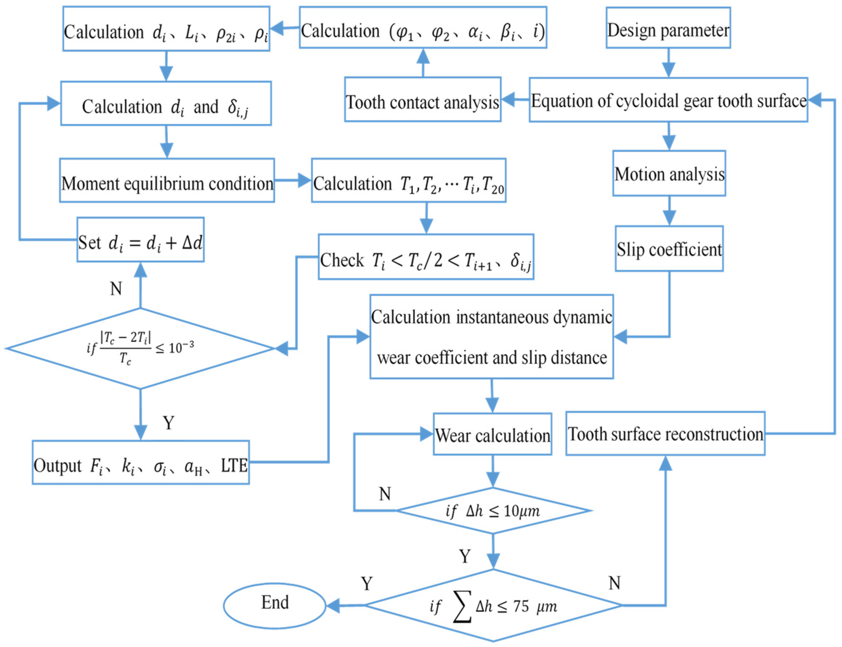
If the cumulative wear of the tooth surface is minor, the tooth surface morphology and load remain almost unchanged. To ensure the efficiency of calculation, this paper reconstructs the tooth profile by setting the worn threshold when the cumulative wear of the tooth surface exceeds the threshold, obtains the geometric parameters and the pressure distribution after the wear, recalculates the relevant parameters, and proceeds to the next iteration until the total cumulative wear amount reaches the wear failure value (the wear amount of one side profile should not exceed 5% of the tooth thickness); then, the iteration is completed. The flow chart of the whole analysis process is as follows in Figure 3.

5. Simulation Results and Analysis

The design parameters of the cycloid–pin gear are shown in Table 1.

5.1. Calculation Results of TCA

The results of UTCA and LTCA are shown in Figure 4. Locally magnified figure A shows no load, only one pair of teeth participate in the meshing, and the transmission error varies periodically from −0.018″ to 0 to 0.018″. The part below the TE curve does not participate in the meshing. The interval between the pin teeth meshing to the meshing is (−0.03959, 0.1177) rad, and the period T is 0.1571 rad. According to the error curve of single-tooth transmission, given any pin gear angle φ 1 , the unique meshing parameters ( φ 2 , α , β , i ) can be determined. The curvature radius of side clearance, contact force arm, and cycloid gear can be further determined.
When the load is 400 Nm, more teeth are engaged, the interval between the pin teeth meshing to the meshing is (−0.985, 0.4193) rad, and the formula is calculated according to the effective coincidence degree
ε = 0.985 + 0.4193 T = 8.94
This indicates that at least eight pairs of teeth are involved in meshing.
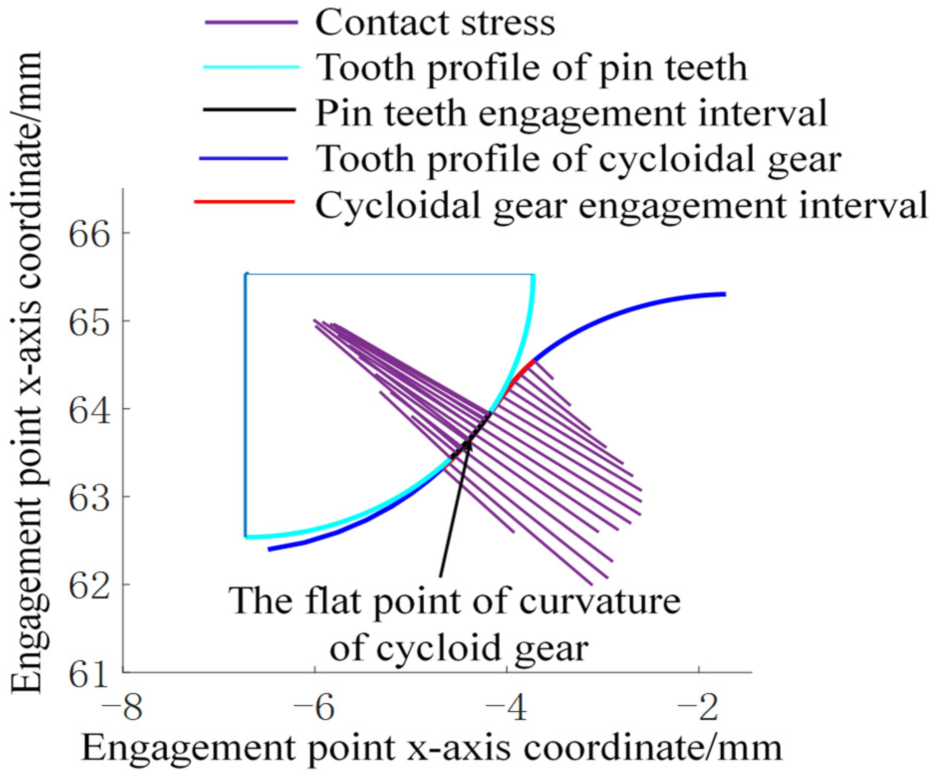
Based on the LTCA analysis of the full-meshing period, the movement and load of the No. 4 pin from meshing to meshing are calculated, as shown in Figure 5. From Figure 5, the tooth profile range and the change law of meshing and meshing load contact force in the process of the cycloid–pinwheel drive can be clearly defined, which lays a foundation for calculating the wear depth of two tooth surfaces when No. 4 pinwheel tooth participates in the meshing drive.

5.2. Dynamic Wear Coefficient

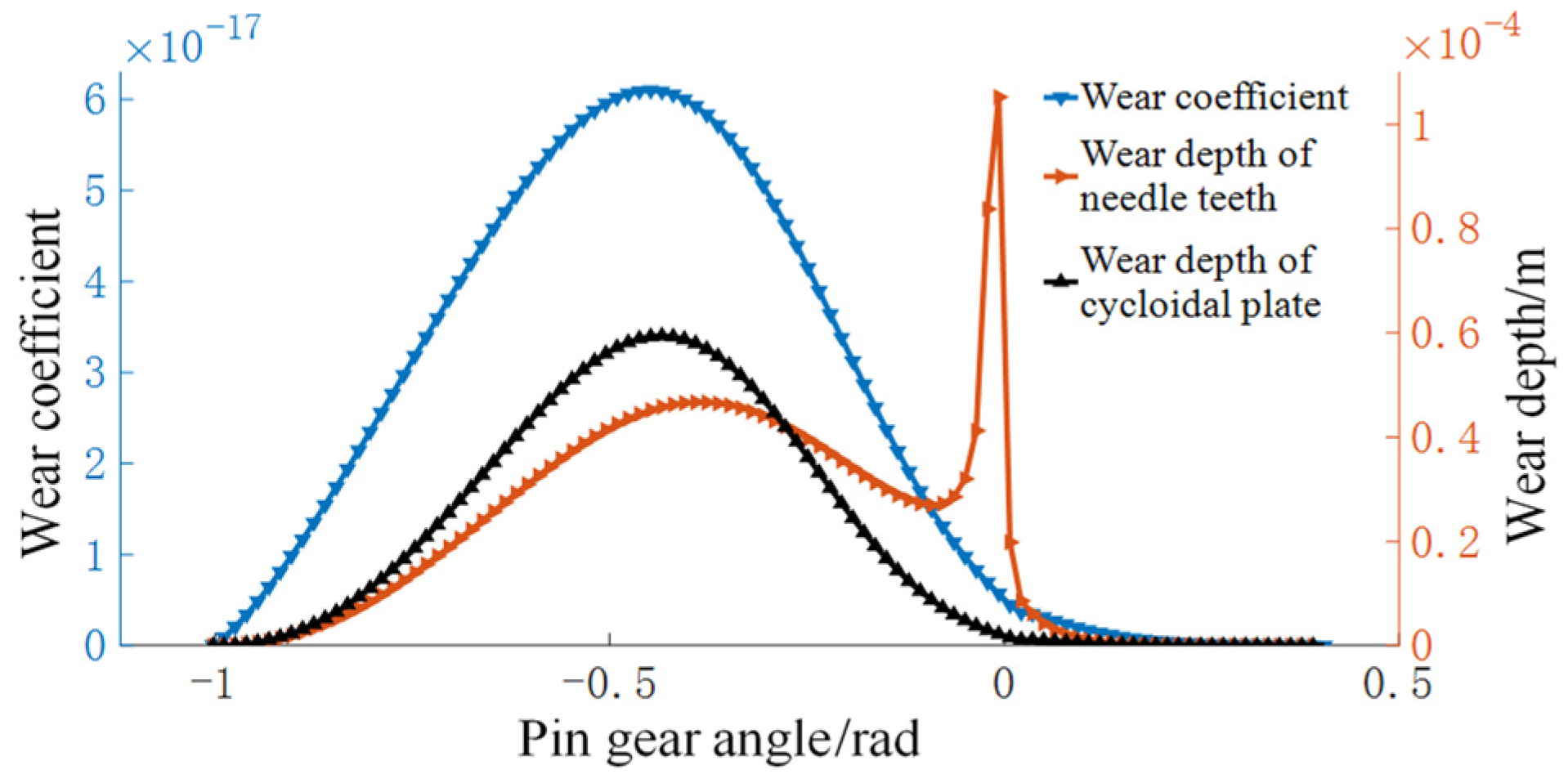
According to the distribution law of the wear coefficient in Figure 6, the wear coefficient first increases and then decreases from the top of the tooth to the root of the tooth. According to Formula (20), the wear coefficient increases with the rise of the load and the roughness of the tooth surface, and the influence of parameter G is the greatest. The wear coefficient and the tooth surface contact stress change trend are consistent.

5.3. Hertz Contact Stress and Contact Half-Width

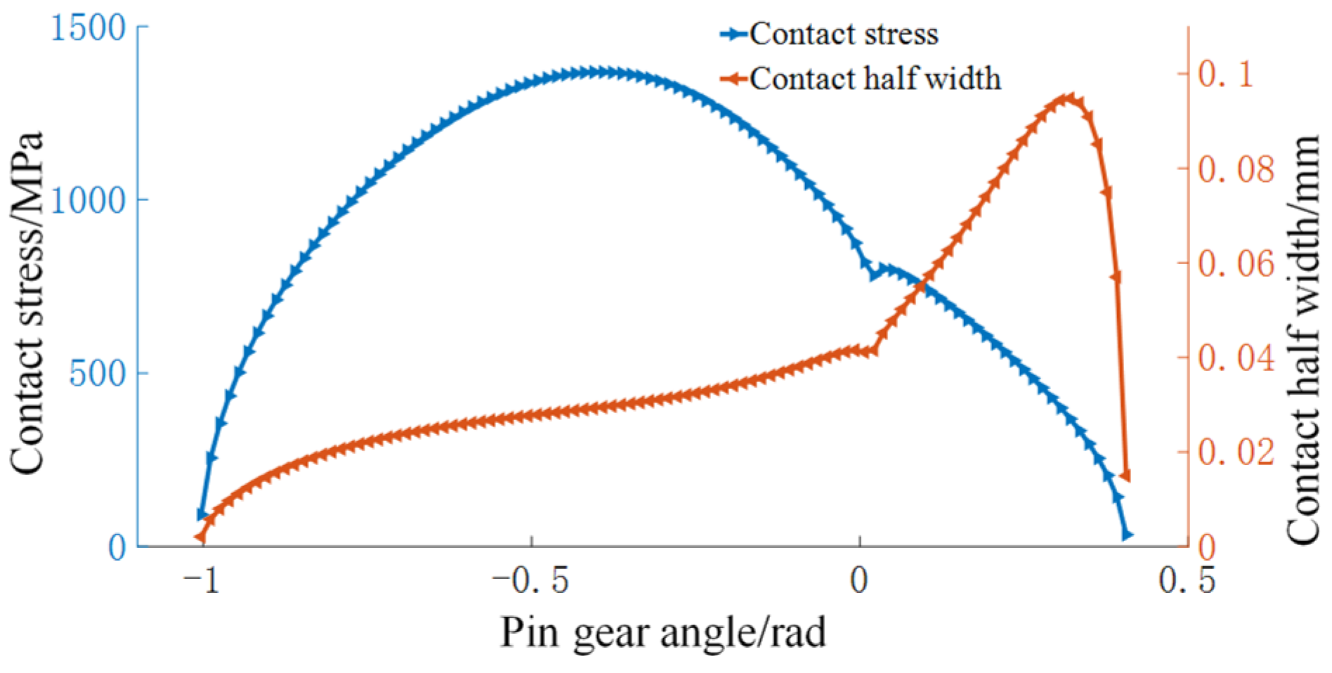
The contact analysis results of the whole meshing area are shown in Figure 7. It can be seen from the graph that, in the entire meshing period, the cycloid gear enters meshing from the top tooth area, the contact stress and the contact half-width first increase and then decrease, and the change in the contact stress is smooth. There is no abrupt change and the two exist at the extreme point at the flat point of the tooth profile. The contact half-width increases sharply at first and then decreases rapidly near the mesh area (tooth root).

5.4. Slip Ratio and Slip Distance

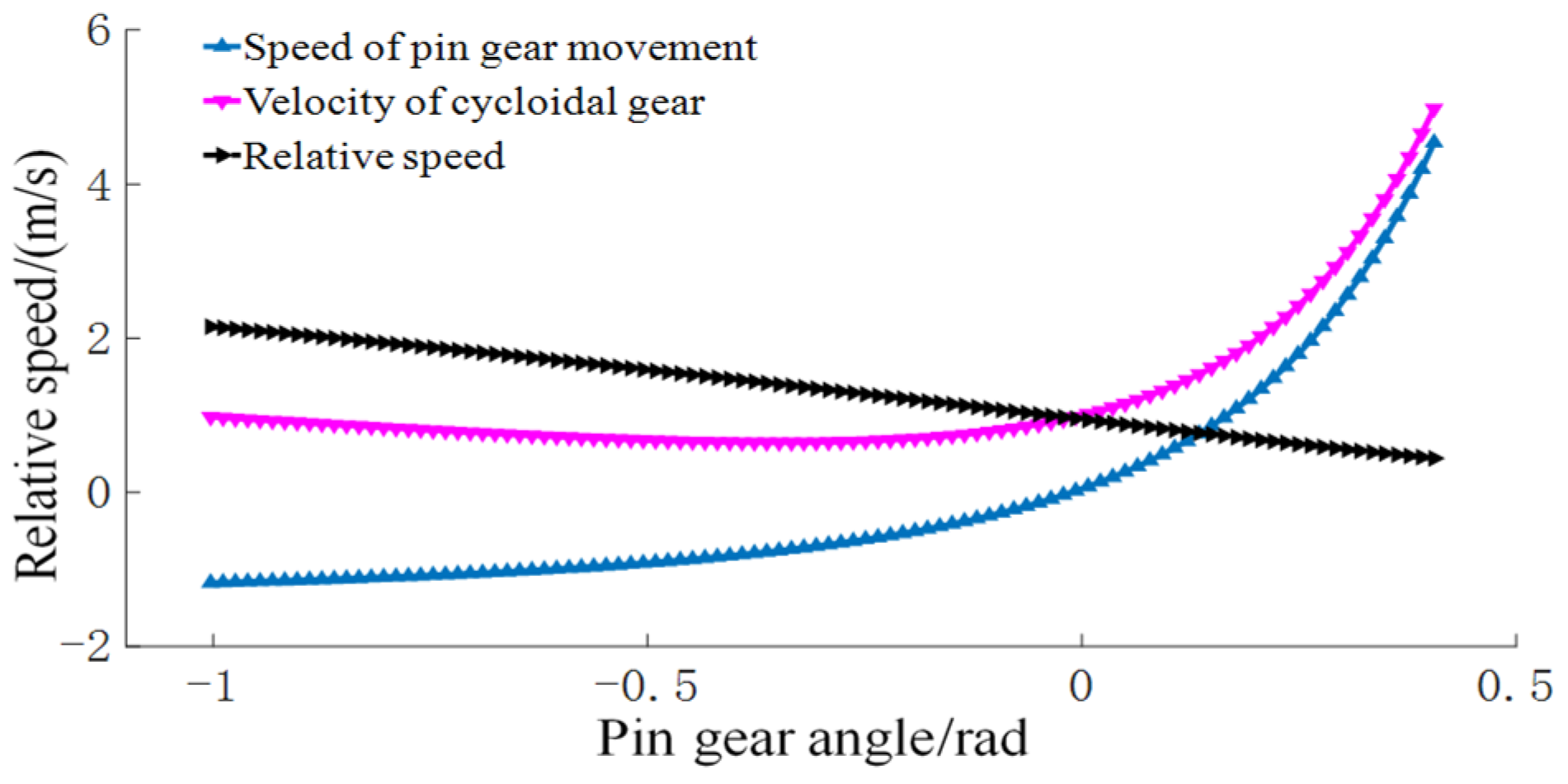
The change in the velocity curve in Figure 8 shows that the rolling velocity of the cycloid tooth is positive, which shows that the movement along the tooth surface is always in one direction during the meshing process. The rolling speed of the needle tooth is positive and negative. When the velocity is 0, the slip coefficient appears infinite, the sliding wear is severe, and the tooth surface is easily glued.
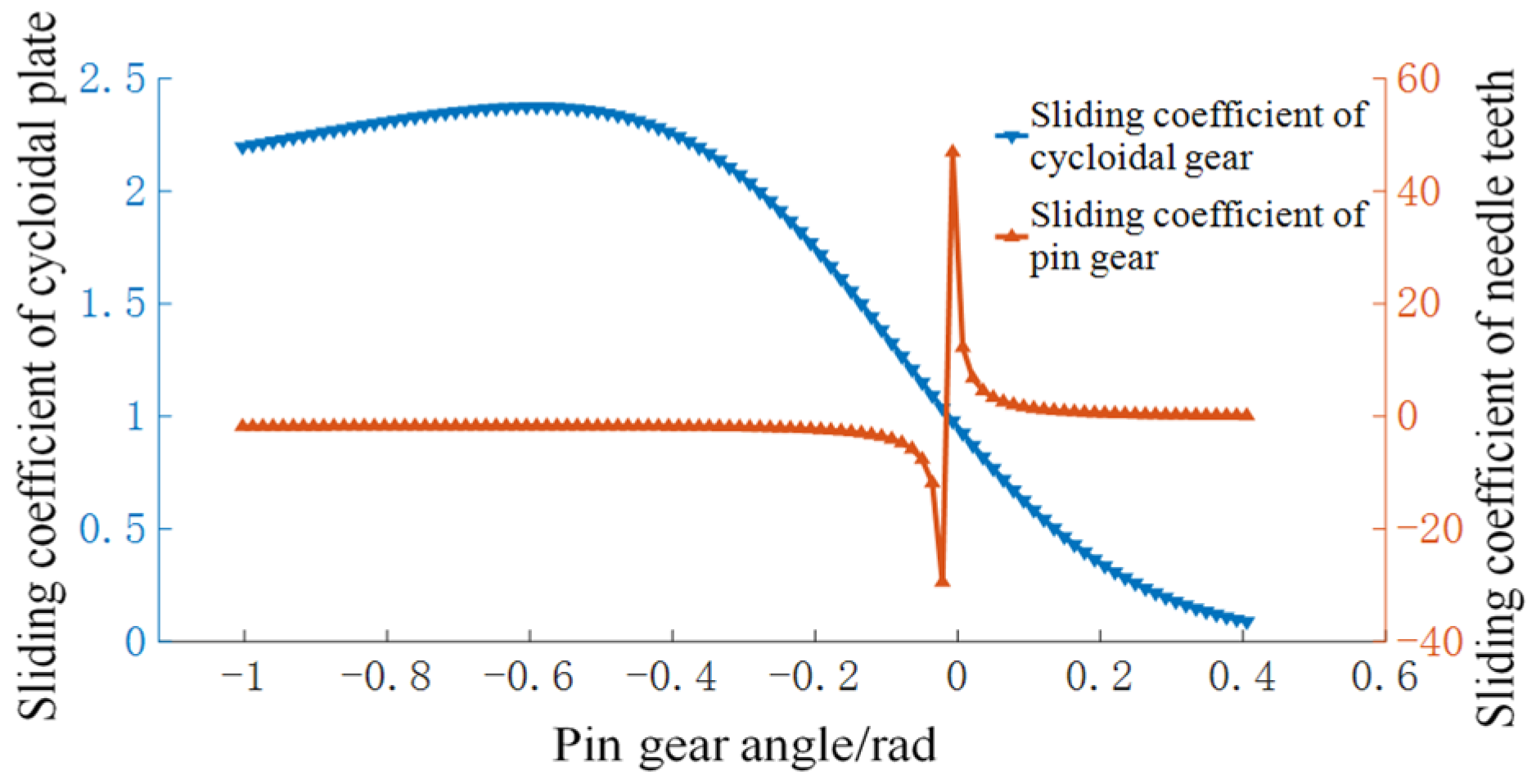
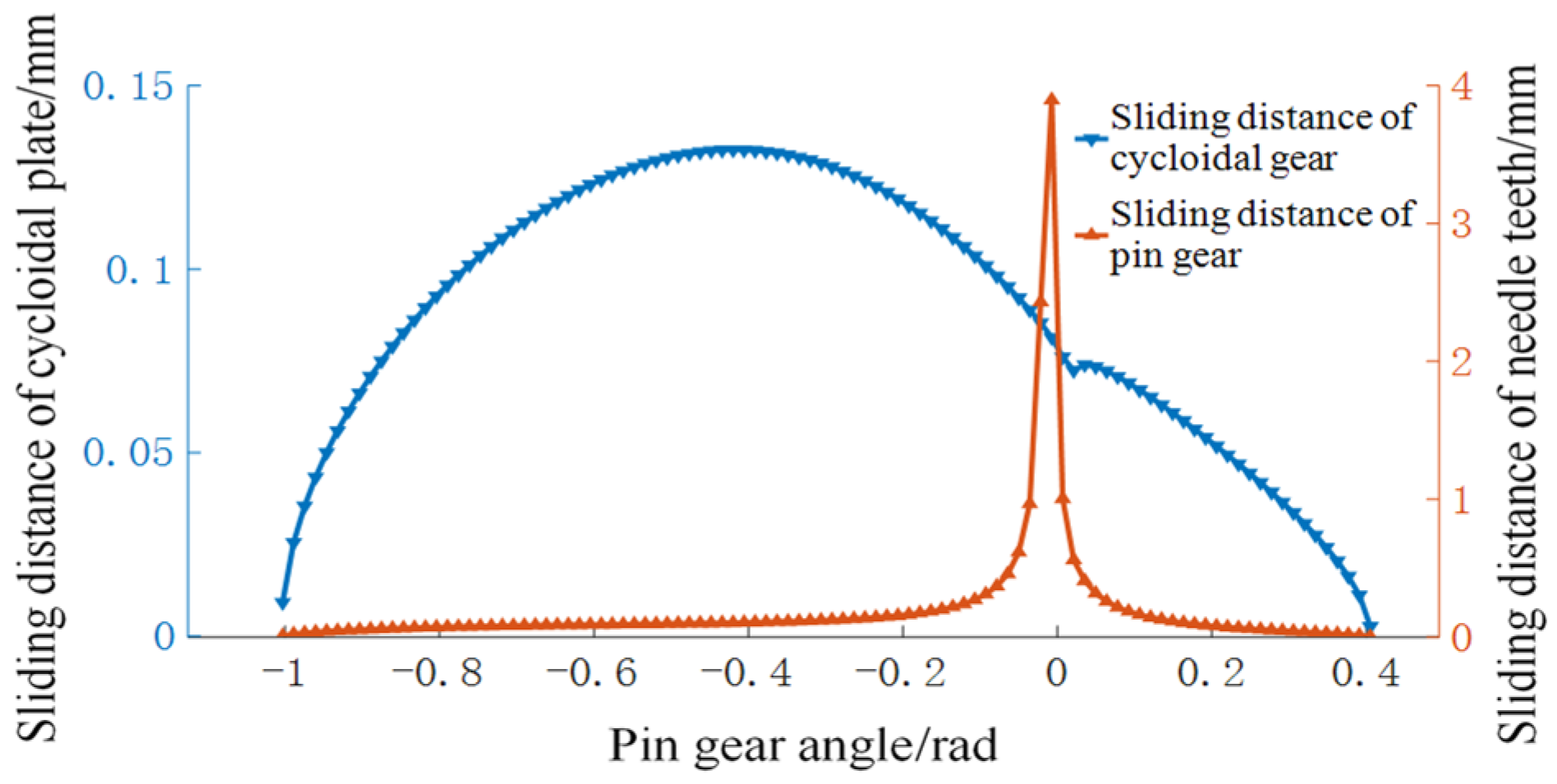
The change in the slip coefficient in Figure 9 shows that the cycloid tooth’s slip coefficient changes significantly. The needle tooth changes the velocity direction when the direction of the meshing line changes, which results in a sudden change in the slip coefficient. In Figure 9, the positive and negative indicate the slip direction, and the slip coefficient is small at other meshing positions. The change in the slip distance in Figure 10 shows that the slip distance of the cycloid tooth increases first and then decreases, and there is an extreme value at the flat point of the tooth profile, and the slip distance of the needle tooth increases first and then decreases; as a result of the abrupt change in the slip coefficient, the slip distance also has a sudden change point.

5.5. Wear Depth

The wear coefficient obtained by experiments in reference [30] is consistent with the wear coefficient obtained by the regression formula in this paper, and the influence of the curvature radius of the cycloid wheel is considered in this paper. This paper describes in detail the calculation of sliding coefficient and sliding distance in the load-bearing meshing section of the cycloid–pin gear, fully considers the particularity of the cycloid tooth profile, and calculates the wear of the load-bearing tooth surface. Reference [30] calculates the wear distribution of the complete tooth profile, but, in practical application, only part of the tooth profile participates in meshing. Therefore, the calculation results are slightly different from this paper.
This study calculates the cycloid and pin gear’s wear depth distribution when the driving gear rotates 3.0 × 10 6 times. Figure 11 shows that the wear depth of the cycloid gear increases first and then decreases from the tooth tip to the tooth root, which is consistent with the trend of wear coefficient and contact stress. Due to the change in the velocity direction in the process of meshing, the distribution of pin tooth wear has a sudden change in the slip coefficient, which leads to the same law of the slip distance. It is easy to cause the gluing of the tooth surface, thus affecting the service life of the cycloid–pin gear. A comprehensive comparison of the wear distribution of the cycloid gear and needle gear shows that the maximum wear of the cycloid gear is 60 μ m in the whole meshing range. The wear of pin teeth is 100 μ m . The wear of pin teeth near the sudden change in speed is greater than that of cycloid teeth, and the wear of cycloid teeth at other meshing parts is greater.
The above analysis is based on the theoretically fixed condition of the pin teeth: the cumulative wear amount is 2.1 mm, and the average wear amount is 21 μm. The self-rotational movements of the pin teeth can make the wear reduce unevenly. The uniform distribution of the wear amount is 4.69 μm, significantly reducing the wear amount. This content is beyond this study’s scope and can be discussed in future literature.

6. Conclusions

This study establishes the wear calculation model of the loaded contact tooth surface of the cycloid–pin gear. The complete calculation process is presented on the wear distribution of the contact tooth surface of the cycloid–pin gear from tooth contact analysis to loaded tooth contact analysis and wear loaded tooth contact analysis. The main conclusions are made as follows:
(1)
The load-bearing contact analysis of the tooth surface determines the coincidence degree of cycloidal pin gear meshing transmission and then determines the meshing interval of a single cycloid tooth, which lays the foundation for the wear analysis of the load-bearing tooth surface.
(2)
Through the motion analysis of cycloidal pin gear drive, the distribution of the sliding coefficient of two tooth surfaces is determined. Because the speed vector is positive and negative during the meshing process of the gear teeth, the slip coefficient suddenly increases at the speed zero point.
(3)
In the whole meshing area, the wear of pin teeth is relatively large at the speed zero point, and the wear in other meshing areas is relatively uniform. The wear of cycloidal gear teeth depends on the contact stress distribution of the tooth surface.

Author Contributions

Y.W. wrote the manuscript; B.W., Z.W., J.Y. and J.X. assisted with result analyses. All authors read and revised the manuscript. All authors have read and agreed to the published version of the manuscript.

Funding

Supported by the National Natural Science Foundation of China (Grant No. 51875174) and Long Men laboratory’s leading-edge research project (Grant No. LMQYTSKT025).

Data Availability Statement

The datasets supporting the conclusions of this article are included within the article.

Conflicts of Interest

The authors declare no conflict of interest.

References

  1. Xu, L.X.; Yang, Y.H. Dynamic modeling and contact analysis of a cycloid-pin gear mechanism with a turning arm cylindrical roller bearing. Mech. Mach. Theory 2016, 104, 327–349. [Google Scholar]
  2. Xu, L.X. A dynamic model to predict the number of pins to transmit load in a cycloidal reducer with assembling clearance. Proc. Inst. Mech. Eng. Part C J. Mech. Eng. Sci. 2019, 233, 4247–4269. [Google Scholar] [CrossRef]
  3. Xu, L.X.; Chen, B.K.; Li, C.Y. Dynamic modelling and contact analysis of bearing-cycloid-pinwheel transmission mechanisms used in joint rotate vector reducers. Mech. Mach. Theory 2019, 137, 432–458. [Google Scholar] [CrossRef]
  4. Yang, Y.; Zhou, G.; Chang, L.; Chen, G. A modelling approach for kinematic equivalent mechanism and rotational transmission error of RV reducer. Mech. Mach. Theory 2021, 163, 104384. [Google Scholar] [CrossRef]
  5. Li, X.; Li, C.; Wang, Y.; Chen, B.; Lim, T.C. Analysis of a cycloid speed reducer considering tooth profile modification and clearance-fit output mechanism. J. Mech. Des. 2017, 139, 033303. [Google Scholar] [CrossRef]
  6. Sun, X.; Han, L.; Wang, J. Tooth modification and loaded tooth contact analysis of China Bearing Reducer. Proc. Inst. Mech. Eng. Part C J. Mech. Eng. Sci. 2019, 233, 6240–6261. [Google Scholar] [CrossRef]
  7. Li, T.; Xu, H.; Tian, M. A Loaded Analysis Method for RV Cycloidal-pin Transmission Based on the Minimum Energy Principle. Stroj. Vestn./J. Mech. Eng. 2020, 66, 655–667. [Google Scholar] [CrossRef]
  8. Song, H. The sliding problem of cycloidal pinwheel planetary transmission. J. East China Inst. Metall. 1988, 2, 79–87. [Google Scholar]
  9. Li, C. Relative motion and sliding coefficient of cycloid pin gear planetary transmission teeth. J. Mech. Transm. 1998, 3, 20–22. [Google Scholar]
  10. Yi, W. Basic Theoretical Research of the Curve-Surface Meshing Planetary Gear Drive with Small Tooth Number Difference; Chongqing University: Chongqing, China, 2012. [Google Scholar]
  11. Wang, S.; Tian, G.; Jiang, X. Analysis on Sliding Velocity of Cycloid Gear Pair during Meshing. Sens. Transducers 2012, 16, 218. [Google Scholar]
  12. Ji, S. Design and Manufacturing Technology of Cycloid-Pin Gear Mechanism; Beijing University of Technology: Beijing, China, 2018. [Google Scholar]
  13. Xu, L.; Li, S.; Wang, W. Sliding ratio for novel cycloidal gear drive. Proc. Inst. Mech. Eng. Part C J. Mech. Eng. Sci. 2018, 232, 3954–3963. [Google Scholar] [CrossRef]
  14. Zhang, B.; Wei, B.; Zhang, R. Research on evolution laws of pitch cones and characteristic values on whole tooth surface of hypoid gears. Mech. Mach. Theory 2022, 174, 104915. [Google Scholar] [CrossRef]
  15. Ding, H. Dynamic Wear Models for Gear Systems; Ohio State University: Columbus, OH, USA, 2007. [Google Scholar]
  16. Brandão, J.A.; Martins, R.; Seabra, J.H.; Castro, M.J. An approach to the simulation of concurrent gear micropitting and mild wear. Wear 2015, 324, 64–73. [Google Scholar] [CrossRef]
  17. Andersson, S. Wear simulation with a focus on mild wear in rolling and sliding contacts. Frict. Wear Wear Prot. 2009, 1–19. [Google Scholar]
  18. Rowe, C.N.; Pererson, M.B.; Winer, W.O. Friction and Wear; Spirnger: Cham, Switzerland, 2013. [Google Scholar]
  19. Flodin, A.; Sndersson, S. Wear Simulation of Spur Gears. Tribo Test 1999, 5, 225–249. [Google Scholar] [CrossRef]
  20. Flodin, A.; Sndersson, S. Simulation of mild wear in helical gears. Wear 2000, 241, 123–138. [Google Scholar] [CrossRef]
  21. Flodin, A.; Sndersson, S. A simplified model for wear prediction in helical gears. Wear 2001, 249, 285–292. [Google Scholar] [CrossRef]
  22. Janakiraman, V.; Li, S.; Kahraman, A. An Investigation of the Impacts of Contact Parameters on Wear Coefficient. J. Tribol. 2014, 136, 031602. [Google Scholar] [CrossRef]
  23. Priest, M.; Taylor, C.M. Automobile engine tribology—Approaching the surface. Wear 2000, 241, 193–203. [Google Scholar] [CrossRef]
  24. Wang, X.S.; Wu, S.J.; Zhou, X.H.; Hu, J.C. Nonlinear dynamics analysis of gear transmission system with wear fault. J. Vib. Shock. 2013, 32, 37–43, 69. [Google Scholar]
  25. Terauchi, Y.; Nagamura, K.; Ikejo, K. Study on friction loss of internal gear drives. JSME Int. J. Ser. 3 Vib. Control. Eng. Eng. Ind. 1991, 34, 106–113. [Google Scholar]
  26. Feng, S.; Mao, J.; Xie, Y. Analysis and calculation of gear mesh stiffness with tooth wear. J. Mech. Eng. 2015, 51, 27–32. [Google Scholar] [CrossRef]
  27. Ning, Z.; Chen, C. A study on wear degradation of internal spur gear under hybrid elastohydrodynamic lubrication. J. Vib. Shock. 2021, 40, 183–191. [Google Scholar]
  28. Shen, Z.; Qiao, B.; Yang, L.; Luo, W.; Yan, R.; Chen, X. Research on Dynamic Response Characteristics and Condition Indicators of Gear Wear Fault. J. Mech. Eng. 2021, 57, 120–131. [Google Scholar]
  29. Su, J.; Li, C. Numerical calculation and analysis of wear of cycloid wheel of RV reducer. J. Mech. Transm. 2021, 45, 41–45. [Google Scholar]
  30. Zhang, R.; Zhou, J.; Wei, Z. Study on transmission error and torsional stiffness of RV reducer under wear. J. Mech. Sci. Technol. 2022, 36, 4067–4081. [Google Scholar] [CrossRef]
  31. Mihailidis, A.; Athanasopoulos, E.; Agouridas, K. EHL film thickness and load dependent power loss of cycloid reducers. Proc. Inst. Mech. Eng. Part C J. Mech. Eng. Sci. 2016, 230, 1303–1317. [Google Scholar] [CrossRef]
  32. Kosse, V. Using hysteresis loop and torsional shock loading to assess damping and efficiency of cyclodrives. In Proceedings of the 14th International Congress on Sound Vibration (ICSV14), Cairns, QL, Australia, 9–12 July 2007; International Institute of Acoustics and Vibration (IIAV): Cairns, Australia, 2007; pp. 1–8. [Google Scholar]
  33. Zhou, C.; Wang, H. An adhesive wear prediction method for double helical gears based on enhanced coordinate transformation and generalized sliding distance model. Mech. Mach. Theory 2018, 128, 58–83. [Google Scholar] [CrossRef]
  34. Wang, H.; Zhou, C.; Lei, Y.; Liu, Z. An adhesive wear model for helical gears in line-contact mixed elastohydrodynamic lubrication. Wear 2019, 426, 896–909. [Google Scholar] [CrossRef]
  35. Wang, H.; Tang, L.; Zhou, C.; Shi, Z. Wear life prediction method of crowned double helical gear drive in point contact mixed elastohydrodynamic lubrication. Wear 2021, 484, 204041. [Google Scholar] [CrossRef]
  36. Kostić, N.; Blagojević, M.; Petrović, N.; Matejić, M.; Marjanović, N. Determination of real clearances between cycloidal speed reducer elements by the application of heuristic optimization. Trans. Famena 2018, 42, 15–26. [Google Scholar] [CrossRef]
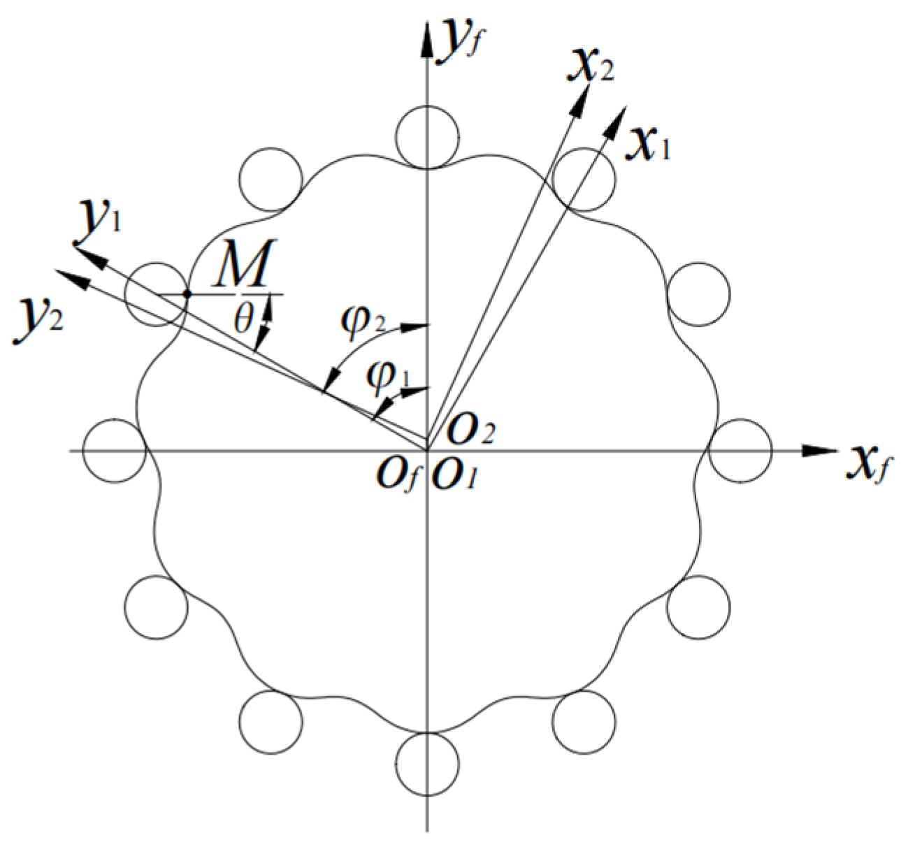
Figure 1. Cycloid gear profile generation coordinate system.
Lubricants 11 00445 g001
Figure 2. Coordinate system of cycloid–pinwheel.
Lubricants 11 00445 g002
Figure 3. Flow chart of contact analysis and wear calculation.
Lubricants 11 00445 g003
Figure 4. LTE curve under rated loads.
Lubricants 11 00445 g004
Figure 5. Contact force distribution of cycloidal pin gear.
Lubricants 11 00445 g005
Figure 6. Regression formula wear coefficient distribution.
Lubricants 11 00445 g006
Figure 7. Contact half-width and contact stress distribution.
Lubricants 11 00445 g007
Figure 8. Velocity distribution at engagement point of cycloidal pin gear.
Lubricants 11 00445 g008
Figure 9. Distribution of slip coefficient at the engagement point of cycloidal pin gear.
Lubricants 11 00445 g009
Figure 10. Distribution of slip distances at the engagement point of cycloidal pin gear.
Lubricants 11 00445 g010
Figure 11. Wear depth distribution of meshing tooth surface of cycloidal pin gear.
Lubricants 11 00445 g011
Table 1. Basic parameters of cycloidal pin gear pair.
ParameterValue
Number of cycloid gear teeth39
Number of pin teeth40
Radius of pin position (mm)66
Poisson ratio0.3
Radius of pin teeth (mm)3
Tooth modification parameter for pin center distance (mm)0.05
Tooth modification parameter for pin radius (mm)0.03
Cycloid gear width (mm)10
Roller gear (mm)22
Elasticity (GPa)206
Eccentricity (mm)1.3
Input torque (Nm)400
Surface roughness of cycloid gear and pin teeth ( μ m ) 0.4
Disclaimer/Publisher’s Note: The statements, opinions and data contained in all publications are solely those of the individual author(s) and contributor(s) and not of MDPI and/or the editor(s). MDPI and/or the editor(s) disclaim responsibility for any injury to people or property resulting from any ideas, methods, instructions or products referred to in the content.