Abstract
In this article, we focus on utilising electrical impedance spectroscopy (EIS) for the assessment of global and contact impedances in roller bearings. Our primary objective is to establish a quantitative prediction of lubricant film thickness in elasto-hydrodynamic lubrication (EHL) and investigate the impedance transition from ohmic to capacitive behaviour as the system shifts from boundary lubrication to EHL. To achieve this, we conduct measurements of electrical impedance, bearing and oil temperature, and frictional torque in a cylindrical roller thrust bearing (CRTB) subjected to pure axial loading across various rotational speeds and supply oil temperatures. The measured impedance data is analysed and translated into a quantitative measure of lubricant film thickness within the contacts using the impedance-based and capacitance-based methods. For EHL, we observe that the measured capacitance of the EHL contact deviates from the theoretical value based on a Hertzian contact shape by a factor ranging from 3 to 11, depending on rotational speed, load, and temperature. The translation of complex impedance values to film thickness, employing the impedance and capacitance method, is then compared with the analytically estimated film thickness using the Moes correlation, corrected for inlet shear heating effects. This comparison demonstrates a robust agreement within 2% for EHL film thickness measurement. Monitoring the bearing resistance and capacitance via EIS across rotational speeds clearly shows the transition from boundary to mixed lubrication as well as the transition from mixed lubrication to EHL. Finally, we have observed that monitoring the electrical impedance appears to have the potential to perform the run-in of bearings in a controlled way.
1. Introduction
The energy efficiency and durability of machines and powertrains are of paramount importance for fostering a more sustainable economy. A key strategy for attaining this objective is the minimisation of both frictional losses and wear damage in bearings [1]. Ideally, bearings operate in the so-called elasto-hydrodynamic lubrication (EHL) regime [2,3], where a thin pressurised lubricant film fully separates the contacting surfaces, such that both friction and wear are minimal. At high loads, low rotational speeds, or low lubricant viscosity, however, mixed lubrication or boundary lubrication may occur, resulting in high friction accompanied by a decrease in energy efficiency. For very high entrainment speeds, shear heating takes place at the rolling contact inlet in the recirculation zone of excess lubricant being repelled. This raises the oil temperature, affecting the oil viscosity and resulting in a thinner lubricant film [4] and an increased risk for mixed lubrication.
The transition from boundary to full-film behaviour represents a dynamic process that depends upon varying operational parameters. These parameters include rotational speed, loading, temperature, and corresponding viscosity, each of which may undergo changes at different rates during machine operation. Given the importance of lubrication in terms of energy efficiency and bearing lifetime, accurate and reliable knowledge of the instantaneous lubricant film thicknesses under all operating conditions would be invaluable. In EHL contacts, which maximally span a few square millimetres, film thicknesses are in the range of 50 nm to 1.5 µm. Owing to the high rotational speeds, the pass-by time of the roller contacts in the bearing falls within the range of 10−5 to 10−3 s, rendering in situ measurement a challenging task.
Hence, this paper aims to contribute to this endeavour by exploring in situ measurement techniques, and more specifically, the electrical impedance spectroscopy technique [5,6], to determine the film thickness in elasto-hydrodynamic conditions as well as the breakdown of the oil film for mixed lubrication. Using such a technique (Figure 1), the complex impedance of lubricated cylindrical roller thrust bearing is measured by applying an AC voltage over the entire bearing, incorporating all contacts with (theoretically) uniform contact conditions. The technique provides rich information on the ohmic and capacitive contributions of the impedance used to distinguish between full-film and mixed lubrication regimes.
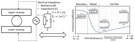
Figure 1.
Lubrication condition and its electrical properties in rolling bearings.
1.1. State of the Art
In the pursuit of our goal, specific techniques for measuring in situ contact parameters, such as film thickness, are most captivating and promising since they enable us to monitor the lubrication condition in real operational scenarios. However, the advancement of such in situ techniques is quite slow due to the challenging physical conditions inherent to EHL contacts [7]. Broadly speaking, in situ measurement techniques for contact conditions can be classified into three groups based on their measurement principle and the correlation of their measured parameter to the desired characteristic within the EHL contacts. The three categories encompass electrical [8], optical [9], and acoustic [10] methods.
Traditionally, EHL film thickness measurements are performed by means of optical interferometric methods [11]. Although such methods are highly accurate, they rely on a fully transparent raceway surface and, hence, are limited to classic ball-on-glass disc laboratory setups, which are not necessarily representative of full metallic bearing contact conjunctions. Acoustic methods, on the other hand, use ultrasonic waves to measure the thickness of the oil film through opaque metal surfaces [12]. They offer non-intrusive measurement but can be complex to integrate into a bearing due to the large sensor size, and the resolution may not always be sufficient for small EHL contacts. Comprehending the underlying principles and recognising the limitations of these techniques is crucial to obtaining reliable results for real applications [13].
Electrical measurement techniques, finally, rely on the electrical conductivity of the involved materials and surfaces, which makes them very well suited for metallic machine components such as roller bearings, even in terms of in situ measurements under transient conditions. Traditionally, voltage discharge, electrical resistance, and capacitance methods have been used as primary methods. Note that all of the aforementioned methods involve, to some extent, the a priori knowledge of specific fluid properties, i.e., optical, acoustic, or electrical, as a function of pressure and temperature.
In the 1950s and 1960s, electrical techniques were used to measure film thickness in an attempt to evaluate whether the results from EHL calculations were plausible. The electrical voltage [14,15] and resistance methods [16,17] enable the assessment of oil film breakdown. The applicability of these methods is, however, limited to scenarios involving light loads, very low speeds, and a simple linear geometry. Moreover, the success was limited due to various issues with the calibration procedures to map the measured variables to a film thickness in the EHL regime. As a result, these methods have found more significant use in exploring the mechanisms of friction and wear under conditions of mixed lubrication than EHL [18,19]. Conversely, the electrical capacitance technique assesses the central EHL film thickness in the contact by gauging the electrical capacitance (Figure 2) [20,21,22,23,24,25], and calculating the Hertzian capacitance CH, approximating the EHL contact shape as Hertzian contact in conjunction with parallel surfaces, i.e.,
where is the relative permittivity of the oil, is the dielectric constant in vacuum, and represents the Hertzian contact area.
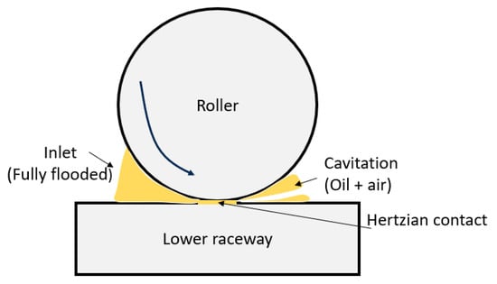
Figure 2.
Single contact of a roller bearing.
Instead of relying on previous correlation, Wilson [26] and later, Cen and Lugt [27] addressed this challenge by generating a calibration curve for a specific load. For a given lubricant, these authors conducted a sweep over a particular range of rotational speeds, measuring the capacitance and bearing temperature. For each rotational velocity, the measured capacitance was mapped against the film thickness calculated using Hamrock and Dowson’s equation. This process established a relationship between film thickness and capacitance, assuming that Hamrock and Dowson’s equation is sufficiently accurate and reliable under the given conditions. The calibration relationship was obtained for oil; however, the authors also applied the obtained correlation to measure the film thickness for grease-lubricated bearings, assuming fully flooded lubrication conditions.
In 1996, Bartz [28] proposed a correction factor for the Hertzian capacitance in order to take into account the capacitance contribution outside the loaded area, i.e., . Indeed, the single contact capacitance in the bearing contains three individual capacitances in parallel, which are for the inlet zone, for the Hertzian contact zone, and for the outlet zone subject to cavitation (Figure 2).
Note that the correction factor depends on the geometry as well as various operating conditions (load, temperature, lubricant, etc.) and has a value between 3 and 4 in the case of initial point contacts (ball on plate), as determined by Bartz [28].
The method was subsequently enhanced by Jablonka et al. [29,30]. In contrast to Bartz [28], these authors demonstrated that oil film thickness could be accurately measured, comparable to the precision of optical methods, by calculating explicitly the electrical capacitances outside the loaded area , instead of lumping its effect into a correction factor (detailed in Section 2.3). Note that these authors considered a fully flooded area including a fully established inlet area , and a cavitating area [31,32,33], whereas for starved lubrication conditions, the flooded area at the inlet of the contact will become smaller [34,35] as well as the cavitating zone. Note that since the dielectric constant of the lubricant depends on the contact pressure and temperature distribution, accurately determining the film thickness from these measurements is challenging. For the specific case of axial rolling element bearings, where all rolling elements are subjected to identical conditions, measuring the global bearing capacitance , allows for the inference of the representative film thickness of all identical contacts.
Under mixed lubrication conditions, the electrical capacitance approach becomes ineffective due to the partial collapse of the oil film. Each contact behaves more as a resistance than a capacitance. Therefore, since 2010, the electric impedance has been preferred to determine the lubrication film thickness [36,37,38,39,40] in EHL as well as the oil-film breakdown occurring in mixed and boundary lubrication [40,41]. The measured impedance consists of an ohmic (or resistive) contribution R and a capacitive contribution C. The ohmic contribution becomes important in cases of direct metallic contact, whereas capacitance is dominant in cases of full-film lubrication.
Schnabel et al. [38] conducted measurements of the complex impedance in EHL contacts and under mixed lubrication conditions, aiming to simultaneously monitor the oil film component (electrical capacitance) and the oil film breakdown component (electrical resistance). However, no quantitative estimates were derived for the oil film thickness or the breakdown ratio. In contrast, Nihira et al. [39] performed quantitative measurements of both the oil film thickness and oil film breakdown ratio concurrently, employing a metallic ball colliding with a plate with lubricating oil in between. Regrettably, due to the uncertainty regarding the extent of the lubricating oil filling in the surrounding EHL contact, they neglected the capacitance outside the loaded area.
Using an electrical model taking into account the capacitance in both the loaded (in the contact area) and unloaded zones (outside the contact area), Maruyama et al. [42] (detailed in Section 2.2) for an EHL point contact derived a mathematical expression for the oil film thickness and oil film breakdown , which is an indicator for the occurrence of metallic contact in EHL contacts, and the relative magnitude of the resistive contribution due to metallic contact to the entire impedance.
In 2018, Maruyama et al. [42] showed that the oil film thickness could be measured with an accuracy comparable to that of optical interferometry for a laboratory ball-on-disc configuration. In 2019, the same authors [43] applied the electrical impedance method to deep-groove ball bearings lubricated with oil at room temperature. They simultaneously determined the oil film thickness and breakdown ratio from the experimentally measured complex impedance. Furthermore, the obtained values for the film thickness were compared against those predicted by Hamrock–Dowson’s equation. In the high-speed range, the measured film thickness values were lower than those predicted by Hamrock and Dowson. An explicit explanation was not provided in their paper.
In 2023, Maruyama et al. [44] monitored the temporal evolution of the electrical impedance of a thrust needle roller bearing. Initially, the film thicknesses obtained from the impedance method were observed to be lower than those predicted by Hamrock and Dowson. A non-zero positive value of the breakdown ratio was observed, indicating mixed lubrication conditions. However, after one hour, the oil film breakdown ratio decreased and the ‘measured’ film thickness tended towards the theoretical value of Hamrock and Dowson. This transient behaviour clearly marked the occurrence of a run-in period for the new bearing.
Recently, in 2023, Yua et al. [45] used the electrical impedance method to determine the frequency response of the EHL contact for different operating conditions using an MTM traction apparatus (ball on steel disc, PCS Instruments). The results enable the identification of equivalent circuit models by fitting parallel resistor-capacitor models. Using high-accuracy optical interferometry measurements obtained in a ball-on-glass setup under the same contact and lubrication conditions as in the MTM, the electrical impedance measurements were correlated against the measured film thickness. This directly linked the measured resistance and capacitance values to the value of the measured central oil film thickness, without the involvement of calculation models.
The literature discussed above predominantly focuses on capacitance- and impedance-based approaches. However, the majority of the literature leans towards the capacitive approach for point contact measurements (ball-on-disc, or ball bearings), which entails complex calculations. Currently, there is a lack of direct comparison between both the method of Jablonka et al. and that of Maruyama et al. to reconstruct the film thickness from capacitance and impedance measurements, respectively, taking into account the accuracy and reliability for different contact loads, speeds, and oil temperatures. Furthermore, the application of both methods to determine EHL line contact film thickness in roller bearings is underexposed. Additionally, the cause of the increasing deviation of the reconstructed film thickness versus the theoretical value of Hamrock and Dowson at higher speeds, as observed by Maruyama, is not clearly reported yet. Finally, to date, there seems to be no detailed information on the transition from ohmic to capacitive behaviour when migrating from mixed to full-film lubrication, though such information would be valuable for understanding load partitioning between the lubricant film and the asperity contacts.
1.2. Goal of the Paper
In the current study, we focus on the direct comparison between the capacitance-based approach of Jablonka et al. [29,30] and the impedance-based approach of Maruyama et al. [42,43,44] for determining the film thickness in the identical EHL line contacts of cylindrical roller thrust bearings (CRTB). The results of both approaches are compared, and their accuracy and reliability are evaluated. The reconstructed film thickness results were compared to Moes’ EHL film thickness equation. The investigations also consider a parametric analysis of the effect of axial load, speed, and supply oil temperature on the measured impedance.
To investigate the reason behind the discrepancies between the film thickness reconstruction and the theoretical values at higher speeds, shear heating effects were included. Shear heating effects are inferred from direct frictional force measurement, oil, and bearing temperatures in combination with the SKF model for frictional torque. Finally, the transition from mixed to full-film lubrication is studied by examining the shift in behaviour from ohmic to capacitive.
In the subsequent sections, we explore the essence of our study. Section 2, ‘Materials and Methods,’ outlines the application of the equivalent electrical circuit for a single EHL contact, the utilisation of the Maruyama and Jablonka methods, and details the specifications of our experimental setup. Section 3 focuses on the ‘Design of Experiments,’ providing insights into the structured experiment employed in our research. Finally, Section 4 unravels the ‘Results’ obtained through our comprehensive study.
2. Materials and Methods
2.1. Equivalent Electrical Circuit of a Single EHL Contact
In full-film lubrication, the lubricating film in between the metallic roller and raceway surfaces behaves like an electrical insulator and hence acts as a capacitance [44,45]. However, under mixed (and boundary) lubrication, the metallic contact of surface asperities allows the conduction of electric currents. Hence, the contact behaves increasingly like an ohmic resistor with an increasing number of asperity contacts.
As depicted in Figure 3, the equivalent electric circuit of a generic EHL line contact, formed by a cylindrical roller with radius and a plate, consists of a capacitive contribution C and a resistive contribution R that are connected in parallel. The overall capacitance C involves the capacitance in the loaded zone (assuming Hertzian conjunction with apparent area and half the contact width), supplemented with a contribution of its direct environment outside the loaded area, i.e., the in- and outlet regions with a total area . represents the central film thickness within the loaded contact area. The resistive part R, in parallel with the capacitance, represents mainly the occurrence of metal-to-metal asperity contacts and is inversely proportional to the apparent area . Breakdown of the lubricant film inside the loaded zone will trigger asperity contact and, hence, mixed lubrication [45]. The total impedance of the contact, as depicted in Figure 3, is thus given by definition as
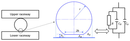
Figure 3.
Electric model for Hertzian tribo-contact [44].
For the specific case of the axially loaded cylindrical roller thrust bearing studied in this work, all rolling elements are subject to identical conditions, and hence identical EHL contacts. It is important to note that skidding is not considered in this case, as the bearing operates under pure rolling conditions during steady-state operation.
The equivalent electric circuit of the entire bearing (N rollers with 2 contacts per roller), as shown in Figure 4, can be considered as N parallel circuits, each one consisting of 2 equivalent contact circuits, as provided in Figure 3, in series [42,43,44]. Hence, with , the impedance of the contact between the k-th roller and the upper raceway, and , the impedance of the contact between the k-th roller and the lower raceway, the total bearing impedance is determined as
in which Z represents the impedance of all identical contacts. Note that the cage is made of an electrically insulating material. Therefore, the impedance of the cage is not taken into consideration.
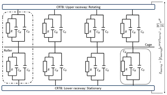
Figure 4.
Electric model for entire roller bearing tribo-contact [44].
To determine the film thickness , Maruyama et al. [42,43,44] relied on the total impedance, i.e., the resistance and capacitance together, whereas Jablonka et al. considered only the capacitive contribution.
2.2. Electrical Impedance-Based Film Thickness Reconstruction: Maruyama’s Method
Maruyama et al. [42,43,44] analytically derived Equations (5)–(8) for line contact EHL. The oil film breakdown parameter represents the resistive contribution to the entire impedance (Equation (5)). denotes the film thickness within the loaded zone of the EHL contact (Equation (6)), whereas denotes the average film thickness, which is calculated using Equation (7). If (EHL) than average film thickness () is equal to . However, in mixed lubrication (), the average film thickness is less than .
where represents the dimensionless number (Equation (8)).
The electrical impedance , with magnitude and phase angle , given in the formula’s above, is obtained by measuring the electrical current as a response to an imposed alternating voltage. The electrical base resistance R10 in Equation (9) is defined as
in which and in Equation (9) are, respectively, the magnitude and phase of the initial impedance Z0 for a stationary lubricated contact where the oil film breakdown factor is unity. Once these parameters are determined at standstill, monitoring the impedance during operation provides directly an estimation for the central and averaged oil film thickness during EHL and/or mixed lubrication (Equation (7)) as well as for the breakdown ratio (Equation (5)) [44].
2.3. Capacitance-Based Film Thickness Reconstruction: Jablonka Method
The method of Jablonka et al. [29,30], initially developed via a ball-on-glass test setup, has been applied to ball bearings (point contacts), as discussed in [35]. Since Jablonka et al. [29,30] considered only the capacitive contribution of the contacts, Equation (4) can be rewritten as
Using Equation (1), the total bearing capacitance for a bearing with equal contact conditions for each roller/ball is defined as
from which the central film thickness can be obtained. Note that implicitly, the assumption is made that the film thickness in the loaded area of the contact is uniform for both the upper and lower raceways, such that in this region, the surfaces are nearly parallel.
The capacitance in the region outside of the loaded zone of the contact (see Figure 2) is given by [29,30].
Equations (11) and (12) are adjusted to accommodate the line contact model [46], incorporating the Hertzian area for a line contact and capacitance outside of the loaded zone .
2.4. Measurement of Electrical Impedance of Roller Bearings
As mentioned previously, the test bearing in this work concerns a purely axially loaded cylindrical roller thrust bearing, in which all contacts are assumed to be identical and representable by the same electrical model of Equation (4), as illustrated in Figure 4. The lubrication state for the EHL contacts in this bearing is typically defined by means of the following three non-dimensional parameters, denoting the dimensionless speed, the dimensionless load, and the lubricant parameter, respectively [47,48] (Figure 1).
in which E′ and R′ are the equivalent Young’s modulus and equivalent radii in the rolling direction, respectively.
To determine the complex impedance , a small AC voltage is imposed over the bearing, and the resulting AC current through the bearing is then measured by means of an oscilloscope, as illustrated in Figure 1. The impedance is then obtained as
with , the phase difference between and .
Since , it becomes clear that the measured impedance is a function of the alternating current frequency . For high frequencies, the contribution of the capacitance is dominant, whereas for low frequencies, the contribution of the resistive part is dominant, with the limiting case of a DC current (), where .
As in the initial step to identify the different lubrication regimes when going from boundary to full-film lubrication, it is crucial to understand how the transition from ohmic to capacitive behaviour varies under different combinations of U, W, and G. Therefore, impedance and phase angle measurements were recorded in a large frequency range of 100 Hz to 1 MHz. The contact resistance R and the contact capacitance C are identified by fitting the equivalent electrical RC model to the impedance spectrum obtained via a frequency sweep [45,49,50]. The identified values for R and C were used to discern the transition between the different lubrication regimes. For the same operating conditions, Moes film thickness correlation was employed to have a quantitative estimate of the lubrication regimes by comparing the film thickness to the average surface roughness.
For film thickness reconstruction, overall bearing impedance and phase angle are measured at a constant frequency of 1 MHz for different operating conditions U, W, and G. The central and average values of the oil film thickness were reconstructed using both Maruyama’s and Jablonka’s method. Given that Maruyama’s method considered impedance Z and phase angle for film thickness reconstruction, the measured raw data and were substituted in Equations (5)–(9). In the case of Jablonka’s method, only the measured capacitance, i.e., , is considered, in accordance with the literature [38,51]. This value is further used in the film thickness Equations (10)–(12). In line with common practice in the literature, the bearing impedance was measured at a constant frequency of 1 MHz in order to obtain a dominant capacitive contribution to the impedance, as seen in Equation (3).
To verify the central oil film thickness obtained by means of both methods under investigation, it is compared with the theoretical value of by the correlations of Moes [52] for a lubricant viscosity at the measured bearing temperature [35]. It is, however, well known that some correction is required in order to account for the inlet shear heating in fully flooded contacts [53]. Such correction is given in the form
is Moes central film thickness, and is central film thickness (Equation (15)) with thermal shear correction factor. For isothermal conditions prevail, whereas for , thermal effects become increasingly important. For pure rolling conditions [54], Equation (16) is used to calculate .
However, in most rolling bearings, micro-slip inherently occurs in the finite-line EHL contacts, making proper evaluation of the correction factor difficult [55]. In the recent work of the authors, a detailed friction-based experimental procedure for thermal shear factor was applied [4]. The same method has been used throughout this work.
To evaluate the lubrication regime in an EHL contact, the ratio of the calculated film thickness and the surface roughness is considered (Equation (17)), and EHL generally occurs for , although this is not a universal value.
2.5. Experimental Setup
In this study, an electrical impedance measurement device from flucon fluid control GmbH [49] was integrated into an in-house-developed vertical-shaft roller bearing test rig, for which the details can be found [4]. The test bearing was a purely axially loaded cylindrical roller thrust bearing (details in Table 1), such that all contacts could be assumed to be equal and representable by the same electrical model. At the bottom, the test chamber is electrically insulated from the test rig by means of a ceramic thrust ball bearing. At the top, the driving shaft is electrically insulated from the test chamber by integrating a ceramic spacer in between the coupling flange and applying insulating bushings around the flange bolts (Figure 5). The AC voltage (RMS amplitude: Vi = 0.6 V) is imposed on the test chamber and the test bearing via a carbon brush in contact with the rotating shaft on top and a fixed cable connected to the (stationary) test chamber.

Table 1.
Test bearing properties.
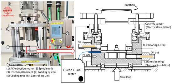
Figure 5.
Overview of RBT and sectional view of the test bearing unit.
A separate lubrication unit supplies lubricant at a controlled temperature and mass flow rate to the test bearing chamber. As a lubricant, FVA 3A (ISO VG100) oil is used, for which the experimentally characterised properties are given in Table 2 and Figure 6.
Table 2.
Properties of FVA 3A oil [56,57].
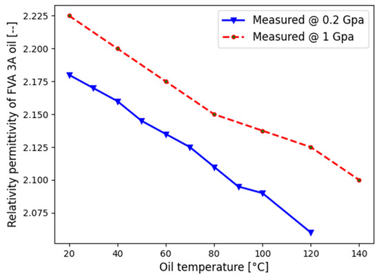
Figure 6.
Relative permittivity as a function of pressure and temperature [56,57].
Besides the electrical current measurements, the temperature of the bearing (PT100), the temperature of the supply oil at the inlet , and the temperature of the oil at the outlet are also recorded. The frictional torque Mt is measured via a lever arm attached to the bearing housing. A load cell is mounted on the electrically insulated frictional arm between the test-bearing housing and the bottom support bearing to measure the tangential frictional force while excluding the shaft support-bearing influence.
3. Design of Experiments and Methodology
The measurement Protocol 1 provides an overview of the experimental workflow. Prior to the experiments, a continuous run-in procedure (see Section 4.1) was performed [58], monitoring the evolution of the ohmic resistance and capacitance to identify the end of run-in. All experimental tests reported in this work were conducted after this run-in period. The methodology for studying average oil film thickness and friction in CRTB contacts is explained in Algorithm 1.
For each set of operating conditions (U, W, G), the system is allowed to reach mechanical and thermal steady-state conditions, implying a constant bearing and oil outlet temperature, and steady-state frictional torques. Once in equilibrium, the electrical impedance Z, the frictional torque Mt, the temperatures , and are recorded for about 30 min. The mean deviation of these variables is less than 1%. These experiments are performed for two bearing loads ( and ) resulting in corresponding Hertzian contact pressures of 0.63 GPa and 1 GPa, respectively, two supply oil temperatures and and rotational velocities ranging from to .
| Algorithm 1 Measurement protocol |
| do run-in procedure |
| do determine the resistance of oil film breakdown area at standstill ( in Equation (9)) |
| for all U, G, W: |
| if Mechanical and thermal equilibrium/steady-state do 1. Measure: |
| 2. Calculate oil film breakdown using (Equation (5)) |
| 3. Calculate central film thickness via Maruyama’s method (Equation (6)) |
| 4. Calculate central film thickness via Jablonka’s method (Equation (11)) |
4. Results
4.1. Run-in Procedure: Reaching Electrical Equilibrium
Before starting the measurement campaign, the fresh cylindrical roller thrust bearings were run in, in order to allow the initial machining roughness to smooth out to a steady-state condition [59]. This ensures stable impedance and film thicknesses during the experiments. The surface roughness of the new rollers and raceways was measured as and , respectively, by means of 3D white light interferometry. The run-in procedure was carried out at a constant rotational speed of at a rather limited axial load of [58]. The impedance Z (Figure 7) was measured every 6 min in a frequency range of 100 Hz to 1 MHz, and the mean value was calculated every 60 min, i.e., after 10 measurements.
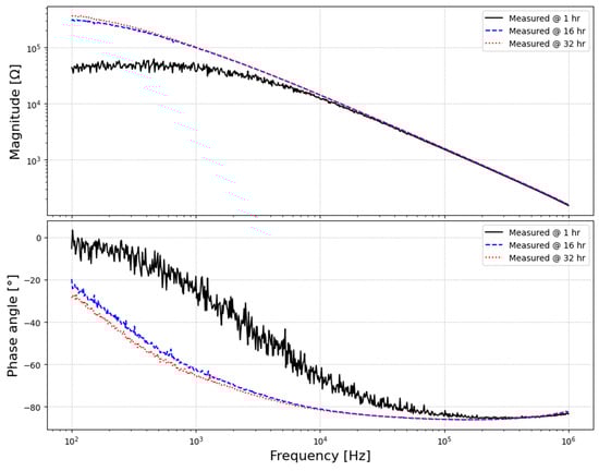
Figure 7.
Measured impedances (top) and phase angle (bottom) during the run-in phase.
Figure 8 shows the time evolution of the bearing capacitance (Figure 8a) and the bearing resistance (Figure 8b), in the measured bearing impedance. It was observed that the capacitance slightly decreased over time, whereas the resistance increased . This reflects the wear during run-in, which makes the metal-to-metal asperity contact decrease over time. Approximately after 30 h of run-in time, the impedance reached a steady state. The variance of the capacitance was about 2–3 pF, whereas the variance of the resistance was 6–8 kΩ. This indicates the consistency and stability of the readings, with minimal variation observed between tests conducted over a period of 28 to 32 h.
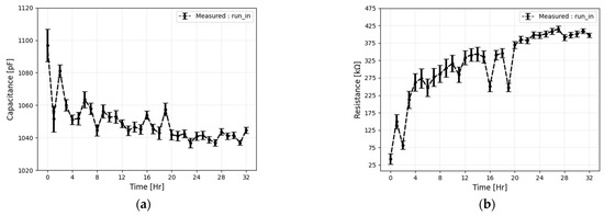
Figure 8.
Behaviour of the (a) capacitance and (b) resistance during the running-in phase.
It can be concluded that a stable lubrication condition had been established at the contacts by the end of the run-in phase. The surface roughness of the roller and raceways was measured after 32 h, providing and , respectively. Note the substantial decrease in the raceways’ roughness of about .
4.2. Transition from Ohmic to Capacitive Behaviour over Lubrication Regimes
In order to ascertain the transition from mixed to full-film lubrication, it is imperative to understand the variation in the ohmic to capacitive transition across different operating conditions. Therefore, impedance measurements were recorded in a large frequency range of 100 Hz to 1 MHz at different rotational speeds, as depicted in Figure 9. As the film thickness increases, the impedance magnitude increases (Figure 9a), while the impedance phase angle decreases (Figure 9b).
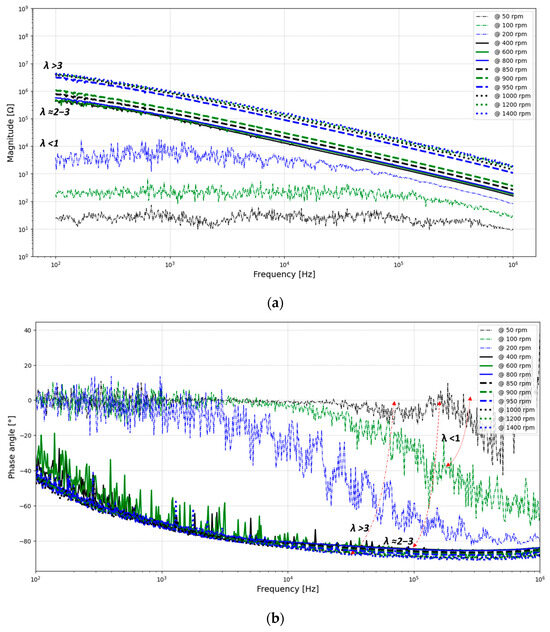
Figure 9.
Measured magnitude (a) and phase angle (b) for varying frequencies and speeds.
The raw data of the amplitude responses are adjusted to the curve of an ideal RC element using least squares regression [49]. The resistive and capacitive contributions are obtained from the measured impedance and plotted in Figure 10. Using the same experimental conditions, we have estimated the ratio of film thickness to surface roughness (λ). This ratio serves as the basis for the placement of the dotted lines in Figure 10.
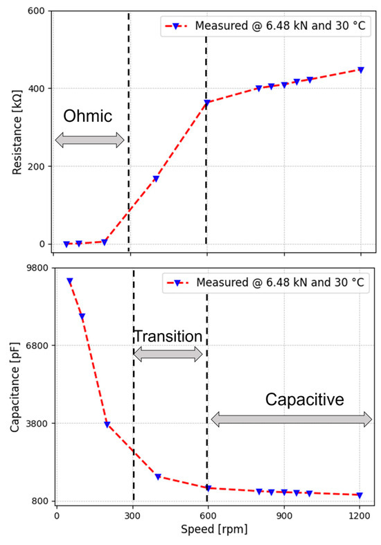
Figure 10.
Identified resistance (top) and capacitance (bottom).
The transition from boundary (ohmic) to full-film lubrication (capacitive) in bearings, analogous to an RC parallel circuit, takes place as the bearings begin functioning, and the lubricating film gradually forms between the contacting surfaces (capacitor starts to charge).
When the bearing operates under boundary lubrication (Figure 10 bottom; higher capacitance), individual asperity contacts act as short circuits, conducting electricity without much resistance, and hence no voltage difference is witnessed between both metallic surfaces. Thus, in this initial state, the circuit behaves ohmic (Figure 10 top; lower resistance). When increasing the rotational speed and, hence, migrating towards mixed lubrication, the capacitance gradually decreases as the contact surface distance increases.
At the same time, the number of asperity contacts decreases, causing a decrease in current passing through the bearing and an increase in resistance. Reaching full lubrication, the circuit primarily exhibits capacitive behaviour.
4.3. Impedance-Based Film Thickness Reconstruction: Maruyama’s Approach
First, we use the method of Maruyama et al. [42,43,44], to calculate the central film thickness, taking into account the full impedance , including the capacitive and resistive contributions. Besides the film thickness, the breakdown of the lubricant film was also assessed. Figure 11 presents the measured impedance and phase angle for varying rotational speeds. Additionally, the bearing frictional torque Mt and bearing temperature were measured (Figure 12) simultaneously.
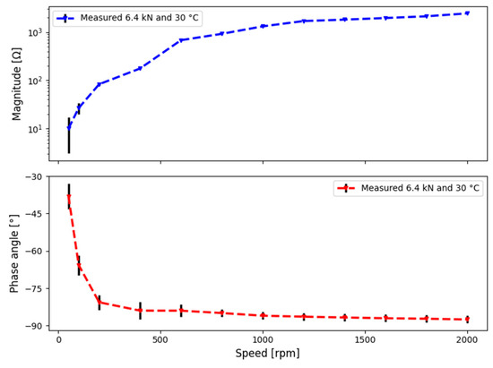
Figure 11.
Measured impedance, magnitude (top), and phase angle (bottom) for varying speeds.
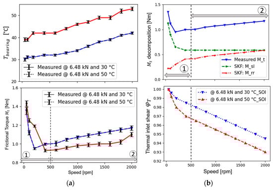
Figure 12.
(a) Measured (top) and (bottom); (b) decomposition (top) and (bottom).
Figure 12a shows the increase in bearing temperature and behaviour of frictional torque in two zones, whereas Figure 12b shows the frictional torque compositions (details in Appendix A) as well as the shear inlet effect as a function of speed. A detailed explanation can be found in [4].
The measured global bearing impedance () and phase angle were used to calculate the average oil film thickness and breakdown ratio using Equations (5)–(9) of Maruyama et al. [42,43,44]. The values for the oil film breakdown factor are shown in Figure 13a as a function of speed and load, whereas the reconstructed central film thickness, as well as the values obtained with the correlations of Moes, are shown in Figure 13b.
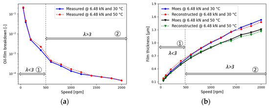
Figure 13.
(a) Oil-film breakdown and (b) comparison of reconstructed and Moes’ film thickness.
At high rotational velocities, an adequate lubricant film is established, separating the roller and raceway surfaces. Hence, the oil film breakdown factor is very low, with values in the order of , indicating full-film EHL. At low rotational velocities, however, the lubricant film is too thin to fully separate the surfaces. Thus, direct metallic contact of opposite asperities occurs, resulting in a fast increase in the value of the oil film breakdown factor with several orders of magnitude up to 0.2 for the lowest rotational speed. It is worth noting that there is no clear-cut distinction between boundary lubrication and mixed lubrication, as evident in Figure 10. This suggests that the parameter may not be particularly sensitive to this transition.
For mixed lubrication conditions (Figure 13b, Zone 1), the central film thickness, obtained by Maruyama’s method, was found to be 6–8% higher in comparison to the values obtained by the correlations of Moes. We emphasise, however, that the Moes correlation is no longer valid, and hence reliable, in mixed lubrication for which corrections would be needed. However, for full-film EHL (Figure 13b, Zone 2), the measured film thickness in the speed range of to was observed to be only 2% higher than the analytically calculated film thickness. Meanwhile, from higher speeds of onwards, Maruyama’s film thickness was 4–5% lower than the calculated one (Moes). This is attributed to the viscous shear heating in the EHL inlet region, requiring a correction factor for Moes’ correlation. Indeed, by correcting Moes’ central film thickness estimate with the correction factor for shear heating effects, which was obtained from frictional torque measurements (as explained in Appendix A), the deviation between both film thickness estimates decreases to about 1.2 to 1.6% for higher rotational velocities, as shown in Figure 14. Note that the measurement accuracy of the device is below ±1%.
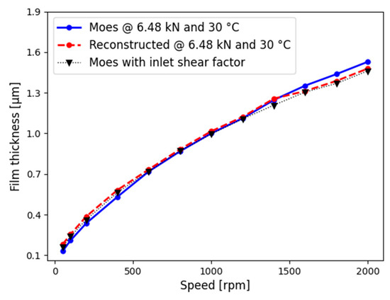
Figure 14.
Film thickness with inlet shear factor.
4.4. Capacitance-Based Film Thickness Reconstruction: Jablonka’s Approach
As explained in Section 2.3, the Jablonka method only considers the capacitance to reconstruct the film thickness. Experiments were conducted under full-film lubrication, where the oil film completely separates the bearing surfaces. Therefore, the imaginary part of the measured can be used to determine the contact capacitance [38,51]. As argued by Bartz [28], the capacitance outside the loaded zone substantially contributes to single-contact capacitance . Indeed, especially for increasing film thickness, the contribution of should increase since the ratio of the non-loaded zones, i.e., the inlet and outlet of the EHL contact, to the loaded zone, i.e., where deformation occurs, also increases. This is confirmed in Figure 15a, which displays the ratio of the total contact capacitance to the contribution as function of the film thickness. The greater the film thickness, the more significant the impact on capacitance from regions outside the loaded area. With an increased film thickness, the portion outside in also increases. This also corresponds to the observations made in the literature [28,29,60]. Indeed, the estimated film thickness using Moes’ [52] and measured capacitance follow (Figure 15b) the same trends as reported by Wilson [26] and Lugt [27].
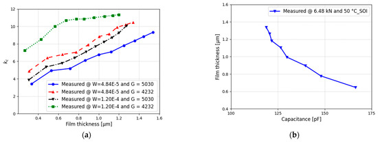
Figure 15.
(a) Behaviour of vs. film thickness and Moes film thickness vs. capacitance (b).
A direct comparison of the film thickness reconstruction by Jablonka et al. [29,30]), using capacitance measurements, with the values obtained via the correlations by Moes, is shown in Figure 16a. Similarly to the impedance-based results of Maruyama et al., we observe a reasonably good correlation between the film thickness values based on the capacitance measurements and those obtained via the Moes fit with inlet shear factor (Figure 16b). In the EHL regime, deviations between both range from −1.5% at lower rotational speeds to a maximum of 1.6% at high rotational speeds.
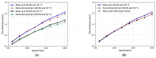
Figure 16.
(a) Reconstructed and Moes film thickness comparison and (b) Film thickness with inlet shear factor.
The results of the comparison indicate that both methods, the electrical approach and Moes’ correlation, exhibit strong performance in predicting EHL film thickness. This suggests a high level of reliability and accuracy in the proposed electrical approach for EHL film thickness measurements.
5. Conclusions
In this article, we focussed on the use of electrical impedance spectroscopy to measure the global and contact impedances in a cylindrical roller thrust bearing, with the aim of determining a quantitative prediction of the lubricant film thickness and analysing the transition from the ohmic to capacitive nature of the impedance when evolving from boundary lubrication to elasto-hydrodynamic lubrication (EHL). Besides the electrical impedance, the bearing temperature and frictional torque are measured in a test bearing, undergoing a pure axial loading for various rotational speeds and oil temperatures. The measured impedance is translated into a quantitative measure of the lubricant film thickness in the contacts, using both the methods of Maruyama et al. [42,43,44] and Jablonka et al. [29,30]. Moreover, the obtained film thicknesses are compared to the analytical film thickness obtained from the correlation of Moes, taking into account shear heating effects at the inlet. Additionally, we investigated the transition from boundary (ohmic) to full-film EHL lubrication (capacitive) behaviour in bearings. The main conclusions in this work are enlisted in the following:
- During the run-in phase of the bearing, the bearing resistance, reflecting the contact resistance, was observed to increase with time to a stationary value, whereas the capacitance was observed to decrease only slightly with time. This reflects the wear during run-in, changing the initial surface roughness of both the raceway and the roller, as proven by a priori and a posteriori measurements. Hence, monitoring the electrical impedance appears to have the potential to perform the run-in of bearings in a controlled way.
- An analogous trend was observed when migrating from boundary lubrication to mixed lubrication and finally towards EHL lubrication. Indeed, inspection of the bearing or contact impedance, and more specifically, the contact resistance and capacitance for various bearing speeds, clearly shows the transition from boundary to mixed lubrication as well as the transition from mixed to EHL lubrication. Although in boundary lubrication the resistive component is quasi-zero, it is observed to increase once mixed lubrication is established and film thickness increases. The capacitance, on the other hand, displays the inverse behaviour. Once EHL is established, the resistive contribution seems to increase at a much slower rate with increasing film thickness, whereas the capacitive component only slightly decreases.
- Monitoring the film breakdown indicator , proposed by Maruyama et al. [42,43,44], as a function of increasing rotational speed, and hence film thickness, very small values () were observed during EHL, whereas the value increases quickly with several orders of magnitude during mixed lubrication up to an order of in boundary lubrication. The breakdown indicator , however, did not show a very clear distinction once transitioning from mixed to boundary lubrication.
- Comparison of the impedance-based and capacitance-based film thickness estimations of, respectively, Maruyama et al. [42,43,44] and Jablonka et al. [29,30] to the analytically estimated film thickness by Moes’ correlation, corrected for inlet shear heating effects, revealed that both methods perform very well for EHL film thickness measurements. Deviations of both methods to the values of Moes were in the order of 1–2%, which is near the measurement uncertainty.
- As part of our ongoing research, our next step involves correlating measured resistance and impedance with predictions of the true-contact area using the Greenwood–Williamson/Tripp model. This correlation will bridge the gap between observed electrical behaviour and surface roughness during the operation, enhancing our understanding of the tribological dynamics of rolling bearings.
6. Patents
The proposed test setup is under IP protection and covered in European patent EP4269827A1.
Author Contributions
Test rig conceptualisation, M.M.; methodology, software and validation, M.M., S.H. and A.H.; resources, M.M.; writing—original draft preparation, M.M.; supervision, D.F. and P.D.B. Project administration, D.F.; funding acquisition, P.D.B. and D.F. All authors have read and agreed to the published version of the manuscript.
Funding
This research was funded by Flanders Make, the strategic research centre for the manufacturing industry of Flanders, Belgium, “ActiLub_SBO” project.
Data Availability Statement
Data are contained within the article.
Acknowledgments
I would like to express my sincere gratitude to Wouter Ost for his invaluable technical support in setting up the test infrastructure.
Conflicts of Interest
The authors declare no conflicts of interest.
Nomenclature
| b | Hertzian half-width contact (m) |
| f | AC frequency (Hz) |
| Central film thickness of the oil (m) | |
| Indentation of the Hertzian contact (m) | |
| Average oil film thickness (m) | |
| Moes central film thickness (m) | |
| j | Imaginary unit |
| r | Roller radius (m) |
| Mean surface velocity (m/s) | |
| t | Time |
| w | Load-per-unit length (Nm) |
| Area of the Hertzian contact (m2) | |
| Flooded area (m2) | |
| Cavitation area (m2) | |
| Apparent contact area (m2) | |
| CRTB | Cylindrical roller thrust bearing |
| C | Capacitance pF |
| Single-contact capacitance (pF) | |
| Hertzian contact capacitance (pF) | |
| Inlet zone capacitance (pF) | |
| Bearing capacitance | |
| Area filled with oil and its capacitance | |
| Cavitation area and its capacitance | |
| Outside loaded area capacitance | |
| Equivalent Young’s modulus (Gpa) | |
| EHL | Elasto-hydrodynamic lubrication |
| F | Applied load (N) |
| Amplitude of alternating current (A) | |
| L | Length of the roller (m) |
| Global frictional torque (Nm) | |
| Vi | RMS input voltage (V) |
| Global frictional torque (Nm) | |
| N | Number of rolling elements |
| RBT | Roller-bearing tribometer |
| R | Resistance (Ohm) |
| Root mean square of roller surface roughness | |
| Root mean square of raceway surface roughness | |
| Resistance of the breakdown area under a stationary contact | |
| Resistance in breakdown area under a dynamic contact | |
| SRR | Slide-to-roll ratio |
| TEHL | Thermo-elasto-hydrodynamic lubrication |
| ). | |
| Bearing temperature (°C) | |
| Oil inlet temperature (°C) | |
| Oil outlet temperature (°C) | |
| Bearing temperature (°C) | |
| U | Dimensionless speed parameter |
| Amplitude of alternating voltage (V) | |
| W | Dimensionless load parameter |
| Reactance of the capacitor (Ohms) | |
| Z | Bearing impedance (Ohms) |
| Modulus of complex impedance under dynamic contact conditions (Ohms) | |
| Single-contact impedance upper and lower raceway | |
| Operating viscosity of the oil at atmospheric pressure (Pas) | |
| Oil film breakdown | |
| Phase angle under dynamic contact (degree) | |
| Phase angle under stationary contact (degree) | |
| Voltage component at 90 degrees | |
| Current component at 90 degrees | |
| Dimensionless number | |
| Pressure viscosity coefficient of lubricant (Pa−1) | |
| Dielectric constant of vacuum | |
| Relative dielectric constant of oil | |
| Dielectric constant of air | |
| Probability of the contract for an asperity with height | |
| ) | |
| Film parameter | |
| Angular frequency of AC voltage (rad/s) | |
| Cut-off frequency | |
| Thermal reduction factor of raceway |
Appendix A
Since the global friction () of the test CTRB is being measured, it primarily consists of the significant contributions from rolling resistance torque () and sliding torque () while minimising drag losses.
Using the SKF model (Equations (A3)–(A6)), the frictional torque of the sliding () and rolling contact () is computed at the same experimental operating conditions and subtracted from the measured total frictional torque (Equation (A6)).
References
- Doll, G.L. Causes and Effects of Bearing Damage. Roll. Bear. Tribol. 2023, 205–231. [Google Scholar] [CrossRef]
- Gohar, R. Elastohydrodynamics; World Scientific: Singapore, 2001; ISBN 1-86094-170-2. [Google Scholar]
- Dowson, D.; Higginson, G.R. Reflections on Early Studies of Elasto-Hydrodynamic Lubrication. Solid Mech. Appl. 2006, 134, 3–21. [Google Scholar] [CrossRef]
- Manjunath, M.; Fauconnier, D.; Ost, W.; De Baets, P. Experimental Analysis of Rolling Torque and Thermal Inlet Shear Heating in Tapered Roller Bearings. Machines 2023, 11, 801. [Google Scholar] [CrossRef]
- Magar, H.S.; Hassan, R.Y.A.; Mulchandani, A. Electrochemical Impedance Spectroscopy (Eis): Principles, Construction, and Biosensing Applications. Sensors 2021, 21, 6578. [Google Scholar] [CrossRef]
- Spikes, H.A. Triboelectrochemistry: Influence of Applied Electrical Potentials on Friction and Wear of Lubricated Contacts. Tribol. Lett. 2020, 68, 90. [Google Scholar] [CrossRef]
- Albahrani, S.; Philippon, D.; Vergne, P.; Bluet, J. A Review of in Situ Methodologies for Studying Elastohydrodynamic Lubrication. Proc. Inst. Mech. Eng. Part J J. Eng. Tribol. 2016, 230, 86–110. [Google Scholar] [CrossRef]
- Siripongse, C.; Rogers, P.R.; Cameron, A. Discharge through Oil Films. Engineering 1958, 186, 146–147. [Google Scholar]
- Gohar, R.; Cameron, A. Optical Measurement of Oil Film Thickness under Elasto-Hydrodynamic Lubrication. Nature 1963, 200, 458–459. [Google Scholar] [CrossRef]
- Dwyer-Joyce, R.S.; Donohoe, C.J.; Drinkwater, B.W. Method and Apparatus for Determining Thickness of a 40Lubricant Film. U.S. Patent 7,066,027, 27 June 2006. [Google Scholar]
- Cameron, A.; Gohar, R. Theoretical and Experimental Studies of the Oil Film in Lubricated Point Contact; The Royal Society Publishing: London, UK, 1966. [Google Scholar]
- Dwyer-Joyce, R.S.; Harper, P.; Drinkwater, B.W. A Method for the Measurement of Hydrodynamic Oil Films Using Ultrasonic Reflection. Tribol. Lett. 2004, 17, 337–348. [Google Scholar] [CrossRef]
- Dwyer-Joyce, R.S.; Reddyhoff, T.; Drinkwater, B.W. Operating Limits for Acoustic Measurement of Rolling Bearing Oil Film Thickness. Tribol. Trans. 2004, 47, 366–375. [Google Scholar] [CrossRef]
- MacConochie, I.O.; Cameron, A. The Measurement of Oil-Film Thickness in Gear Teeth. J. Basic Eng. 1960, 82, 29–34. [Google Scholar] [CrossRef]
- Dyson, A. Investigation of the Discharge-Voltage Method of Measuring the Thickness of Oil Films Formed in a Disc Machine under Conditions of Elastohydrodynamic Lubrication. Proc. Inst. Mech. Eng. 1966, 181, 633–652. [Google Scholar] [CrossRef]
- Lane, T.B.; Hughes, J.R. A Study of the Oil-Film Formation in Gears by Electrical Resistance Measurements. Br. J. Appl. Phys. 1952, 3, 315. [Google Scholar] [CrossRef]
- Furey, M.J. Metallic Contact and Friction between Sliding Surfaces. ASLE Trans. 1961, 4, 1–11. [Google Scholar] [CrossRef]
- Lord, J.; Larsson, R. Film-Forming Capability in Rough Surface EHL Investigated Using Contact Resistance. Tribol. Int. 2008, 41, 831–838. [Google Scholar] [CrossRef]
- Lugt, P.M.; Severt, R.W.M.; Fogelströ, J.; Tripp, J.H. Influence of Surface Topography on Friction, Film Breakdown and Running-in in the Mixed Lubrication Regime. Proc. Inst. Mech. Eng. Part J J. Eng. Tribol. 2001, 215, 519–533. [Google Scholar] [CrossRef]
- Crook, A. The Lubrication of Rollers. Philos. Trans. R. Soc. B Biol. Sci. 1958, 250, 387–409. [Google Scholar] [CrossRef]
- Crook, A.W. Elastohydrodynamic Lubrication of Rollers. Nature 1961, 190, 1182–1183. [Google Scholar] [CrossRef]
- Dyson, A.; Naylor, H.; Wilson, A.R. Paper 10: The Measurement of Oil-Film Thickness in Elastohydrodynamic Contacts. Proc. Inst. Mech. Eng. Conf. Proc. 1965, 180, 119–134. [Google Scholar] [CrossRef]
- Chua, W.H.; Stachowiak, G.W. The Study of the Dynamic Thickness of Organic Boundary Films under Metallic Sliding Contact. Tribol. Lett. 2010, 39, 151–161. [Google Scholar] [CrossRef]
- Hamilton, G.M.; Moore, S.L. First Paper: Measurement of the Oil-Film Thickness between the Piston Rings and Liner of a Small Diesel Engine. Proc. Inst. Mech. Eng. 1974, 188, 253–261. [Google Scholar] [CrossRef]
- Sherrington, I.; Smith, E.H. Experimental Methods for Measuring the Oil-Film Thickness between the Piston-Rings and Cylinder-Wall of Internal Combustion Engines. Tribol. Int. 1985, 18, 315–320. [Google Scholar] [CrossRef]
- Wilson, A.R. The relative thickness of grease and oil films in rolling bearings. Proc. Inst. Mech. Eng. 1979, 193, 185–192. [Google Scholar] [CrossRef]
- Cen, H.; Lugt, P.M. Film Thickness in a Grease Lubricated Ball Bearing. Tribol. Int. 2019, 134, 26–35. [Google Scholar] [CrossRef]
- Barz, M. Die Schmierfilmbildung in Fettgeschmierten Schnellaufenden Spindellagern. Ph.D. Dissertation, Leibniz Universität Hannover, Hanover, Germany, 1996. [Google Scholar]
- Jablonka, K.; Glovnea, R.; Bongaerts, J. Evaluation of EHD Films by Electrical Capacitance. J. Phys. D Appl. Phys. 2012, 45, 385301. [Google Scholar] [CrossRef]
- Jablonka, K.; Glovnea, R.; Bongaerts, J.; Morales-Espejel, G. The Effect of the Polarity of the Lubricant upon Capacitance Measurements of EHD Contacts. Tribol. Int. 2013, 61, 95–101. [Google Scholar] [CrossRef]
- Otsu, T.; Tanaka, H.; Izumi, N.; Sugimura, J. Effect of Surrounding Gas on Cavitation in EHL. Tribol. Online 2009, 4, 50–54. [Google Scholar] [CrossRef]
- Otsu, T.; Tanaka, H.; Sugimura, J. Initiation and Growth of Gaseous Cavity in Concentrated Contact in Various Surrounding Gases. Tribol. Int. 2012, 53, 68–75. [Google Scholar] [CrossRef]
- van Emden, E.; Venner, C.H.; Morales-Espejel, G.E. Aspects of Flow and Cavitation around an EHL Contact. Tribol. Int. 2016, 95, 435–448. [Google Scholar] [CrossRef]
- Nogi, T. An Analysis of Starved EHL Point Contacts with Reflow. Tribol. Online 2015, 10, 64–75. [Google Scholar] [CrossRef]
- Shetty, P.; Meijer, R.J.; Osara, J.A.; Lugt, P.M. Measuring Film Thickness in Starved Grease-Lubricated Ball Bearings: An Improved Electrical Capacitance Method. Tribol. Trans. 2022, 65, 869–879. [Google Scholar] [CrossRef]
- Manabe, K.; Nakano, K. Breakdown of Oil Films and Formation of Residual Films. Tribol. Int. 2008, 41, 1103–1113. [Google Scholar] [CrossRef]
- Nakano, K.; Manabe, K. Breakdown Processes of Boundary Films Formed by Oiliness Additives. Tribol. Online 2011, 6, 277–283. [Google Scholar] [CrossRef]
- Schnabel, S.; Marklund, P.; Minami, I.; Larsson, R. Monitoring of Running-in of an EHL Contact Using Contact Impedance. Tribol. Lett. 2016, 63, 35. [Google Scholar] [CrossRef]
- Nihira, T.; Manabe, K.; Tadokoro, C.; Ozaki, S.; Nakano, K. Complex Impedance Measurement Applied to Short-Time Contact Between Colliding Steel Surfaces. Tribol. Lett. 2015, 57, 29. [Google Scholar] [CrossRef]
- De Gaetano, D.; Zhu, W.; Sun, X.; Chen, X.; Griffo, A.; Jewell, G.W. Experimental Ball Bearing Impedance Analysis Under Different Speed and Electrical Conditions. IEEE Trans. Dielectr. Electr. Insul. 2023, 30, 1312–1321. [Google Scholar] [CrossRef]
- Graf, S.; Werner, M.; Koch, O.; Götz, S.; Sauer, B. Breakdown Voltages in Thrust Bearings: Behavior and Measurement. Tribol. Trans. 2023, 66, 488–496. [Google Scholar] [CrossRef]
- Maruyama, T.; Nakano, K. In Situ Quantification of Oil Film Formation and Breakdown in EHD Contacts. Tribol. Trans. 2018, 61, 1057–1066. [Google Scholar] [CrossRef]
- Maruyama, T.; Maeda, M.; Nakano, K. Lubrication Condition Monitoring of Practical Ball Bearings by Electrical Impedance Method. Tribol. Online 2019, 14, 327–338. [Google Scholar] [CrossRef]
- Maruyama, T.; Radzi, F.; Sato, T.; Iwase, S.; Maeda, M.; Nakano, K. Lubrication Condition Monitoring in EHD Line Contacts of Thrust Needle Roller Bearing Using the Electrical Impedance Method. Lubricants 2023, 11, 223. [Google Scholar] [CrossRef]
- Yu, M.; Zhang, J.; Joedicke, A.; Reddyhoff, T. Using Electrical Impedance Spectroscopy to Identify Equivalent Circuit Models of Lubricated Contacts with Complex Geometry: In-Situ Application to Mini Traction Machine. Tribol. Int. 2024, 192, 109286. [Google Scholar] [CrossRef]
- Furtmann, A. Elektrisches Verhalten von Maschinenelementen im Antriebsstrang, Leibniz Universitat Hannover. Ph.D. Dissertation, Leibniz Universität Hannover, Hanover, Germany, 2017. [Google Scholar]
- Gonda, A.; Capan, R.; Bechev, D.; Sauer, B. The Influence of Lubricant Conductivity on Bearing Currents in the Case of Rolling Bearing Greases. Lubricants 2019, 7, 108. [Google Scholar] [CrossRef]
- Kirchner, E.; Bienefeld, C.; Schirra, T.; Moltschanov, A. Predicting the Electrical Impedance of Rolling Bearings Using Machine Learning Methods. Machines 2022, 10, 156. [Google Scholar] [CrossRef]
- Hausner, S.; Bode, B.; Heine, A.; Kießling, M.; Klingebiel, J.; Thiel, C. E-Lub Tester – Lubricant Impedance & Electrical Breakdown Test Rig: flucon fluid control GmbH 2023. Available online: https://flucon.de/en/products/e-lub-tester/ (accessed on 15 January 2023).
- Muetze, A.; Binder, A. Calculation of Motor Capacitances for Prediction of the Voltage Across the Bearings in Machines of Inverter-Based Drive Systems. IEEE Trans. Ind. Appl. 2007, 43, 665–672. [Google Scholar] [CrossRef]
- Schirra, T.; Martin, G.; Puchtler, S.; Kirchner, E. Electric Impedance of Rolling Bearings—Consideration of Unloaded Rolling Elements. Tribol. Int. 2021, 158, 106927. [Google Scholar] [CrossRef]
- Moes, H. Lubrication and Beyond; Lecture Notes, Code 115531; Twente University Press: Enschede, The Netherlands, 2000; 366p, Available online: https://www.researchgate.net/publication/259757915_Moes_H_Lubrication_and_Beyond_Lecture_Notes_Code_115531_Twente_University_Press_Enschede_Netherlands_2000_366_p (accessed on 15 January 2023).
- Echávarri Otero, J.; de la Guerra Ochoa, E.; Chacón Tanarro, E.; Franco Martínez, F.; Contreras Urgiles, R.W. An Analytical Approach for Predicting EHL Friction: Usefulness and Limitations. Lubricants 2022, 10, 141. [Google Scholar] [CrossRef]
- Bearing Friction, Power Loss and Starting Torque|SKF. Available online: https://www.skf.com/group/products/rolling-bearings/principles-of-rolling-bearing-selection/bearing-selection-process/operating-temperature-and-speed/bearing-friction-power-loss-and-starting-torque (accessed on 23 August 2022).
- Spikes, H. Basics of EHL for Practical Application. Lubr. Sci. 2015, 27, 45–67. [Google Scholar] [CrossRef]
- Simon, M. Messung von Elasto-Hydrodynamischen Parametern und Ihre Auswirkung auf die Grübchentragfähigkeit Vergüteter Scheiben und Zahnräder. Ph.D. Dissertation, Technische Universität Braunschweig, Braunschweig, Germany, 1984. [Google Scholar]
- Kreil, O.; Schouten, M.J.W. Einfluss der Oberflächenstruktur auf Druckverteilung und Schmierfilmdicke im EHD-Kontakt. Ph.D. Dissertation, Technische Universität München, Munich, Germany, 2008. [Google Scholar]
- NSK Ltd. Roller Bearing Catalogue, E1254j; NSK Ltd.: Tokyo, Japan, 2019. [Google Scholar]
- Chen, S.; Han, Z.; Zeng, Q.; Wang, B.; Wang, L.; Guo, L.; Shao, Y. Influence of Manufacturing Surface Topography on Torque and Load Bearing Capacity of Hydro-Viscous Drive Clutch under Mixed Lubrication Stage. Ind. Lubr. Tribol. 2024, 76, 81–90. [Google Scholar] [CrossRef]
- Schneider, V.; Liu, H.-C.; Bader, N.; Furtmann, A.; Poll, G. Empirical Formulae for the Influence of Real Film Thickness Distribution on the Capacitance of an EHL Point Contact and Application to Rolling Bearings. Tribol. Int. 2021, 154, 106714. [Google Scholar] [CrossRef]
Disclaimer/Publisher’s Note: The statements, opinions and data contained in all publications are solely those of the individual author(s) and contributor(s) and not of MDPI and/or the editor(s). MDPI and/or the editor(s) disclaim responsibility for any injury to people or property resulting from any ideas, methods, instructions or products referred to in the content. |
© 2024 by the authors. Licensee MDPI, Basel, Switzerland. This article is an open access article distributed under the terms and conditions of the Creative Commons Attribution (CC BY) license (https://creativecommons.org/licenses/by/4.0/).