Abstract
An understanding of the proper application of metalworking fluids (MWFs) is necessary for their implementation in efficient production processes. In addition, the knowledge of the process-related aspect of chip transport and the macroscopic cooling effect, the characteristics and properties of lubricant film formation, and the cooling conditions in the secondary shear zone on the chip surface, i.e., in the direct vicinity of the material separation, represent a combined fundamental scientific issue within production engineering. The aim is to transfer methods from the field of tribology of machine elements, which have already led to a considerable gain in knowledge in this discipline, to machining and to couple them with already established approaches to machining. In the case of roller bearings, the contact pressure is in the range as the pressure in the contact zone between the cutting insert and chip. Due to this, established methods might be transferred to the cutting process. In addition to classical pin-on-plate and pin-on-ring friction investigations, film thickness measurements were carried out and compared to machining tests. The coefficient of friction determined in the planing test rig is 0.48 for dry cutting, while it is 0.47 for wet cutting. These two values are much larger than the CoF with MWFs measured on the two tribometers. It is shown that the boundary friction of MWF especially influences the machining process. Thus, additives in MWF might have a high significance in machining.
1. Introduction
The application of metalworking fluids (MWF) in machining can significantly reduce the thermomechanical load and increase the component quality and the metal removal rate [1,2,3,4]. However, the potential of an efficient MWF usage can only be fulfilled if the properties of the MWF and, in particular, its flow rate are specifically matched to the material to be machined and to the process parameters [4,5,6,7]. Knowing the amount of metalworking fluid required also offers the potential for reducing the waste of resources that is currently not being exploited [7]. For environmental protection and resource efficiency, minimum quantity lubrication (MQL) and biolubricants offer a high potential [8,9,10]. In the case of biolubricants under MQL conditions, Safie et al. investigated rice bran oil, neem oil, and castor oil and showed some benefits with castor oil [11]. Compared with mineral cutting fluid, vegetable-oil-based emulsion can feature better properties for the turning of AISI 1050 steel by improving machinability as shown by Carvalho et al. [12].
In the tribological system of machining, chip formation, loading, friction and wear, as well as the properties of the contact pairs (cutting tool/workpiece material) and the intermediate medium (MWF) form a closed loop. Due to the complexity of the tribological system, both a consideration of the overall system and a structured analysis of the individual components and their interaction are required. Rech et al. [13] investigated the influence of various cooling strategies (dry, oil, emulsion) on the coefficient of friction (CoF) on a test rig under machining-relevant pressures (3 GPa) and relative speeds (up to 300 m/min). It was found that friction losses can be significantly reduced by using lubricating oil and emulsions. The greatest influence was found in the tests by using oil-based lubricants. As a result of the reduction in friction, a significant reduction in frictional heat was also observed. In addition, the cooling effect of the MWF favors the dissipation and removal of the heat generated during machining processes [1,4].
MWFs also have a positive effect on reducing the wear of cutting tools. For example, Lakner and Hardt [14] demonstrated for the material Ti-6Al-4V that increased MWF supply pressure significantly reduces tool wear. A large group of MWFs are water-miscible oils that are highly additivated and mixed with water [1,15]. The oil is usually additivated with emulsifiers to keep the oil dissolved in small droplets in water, with extreme pressure (EP) additives to protect surfaces, and with rust preventive additives [1,16]. They provide very good lubrication and heat dissipation and are most commonly used in industry. The trend to use water-based emulsions can be found recently in the application for bearing lubrication [17]. Future trends for lubrication utilize graphene-mixed aluminum oxide as hybrid nano-additives as shown by Lim et al. [18].
Under harsh conditions in metalworking, the boundary conditions of the surfaces in contact play a crucial role. The formation of boundary films due to additives in cutting fluids was in the focus of Ma et al. applying ball-on-disc tests [19]. It could be shown on an Al–Mn substrate, that a phosphorus rich boundary film is formed on the surface. In this case, interfacial films of EP additives reduce friction [16]. Depending on the temperature, specific additives react with the surfaces; for example, sulfur-based additives can reach up to 1000 °C [20]. These additives form dense layers by physical adsorption and chemical reaction with the metallic surfaces [1,21]. Schulz et al. investigated the interactions of additives for MWFs on metallic surfaces in terms of Brugger lubrication tests. Based on their experiments, they predicted the adsorption of additives on the metallic surfaces [22].
The formation of boundary layers is usually influenced by temperature as well as tangential shear stresses [23]. Studies on these mechanochemical effects are carried out from the nano to the macro scale to understand the film formation processes [24]. Nano-indentation studies can be used to derive the mechanical properties of such interfacial films [25,26]. Additional beneficial effects for later application can be achieved by MWFs, as investigated by Britt et al. [27]. In this study, ToF-SIMS (time-of-flight secondary mass spectrometry) has been performed on surface layers achieved at various exposure temperatures of the MWF on cleaned surfaces to conclude on the formation of boundary layers. Additionally, the emulsifier influences the film formation in sliding contacts. Previous studies have shown that the emulsifiers prevent full film lubrication at high speeds in experiments [28,29]. In order to gain knowledge about the influence of MWF on the machining process, the tribological influence on friction in the secondary sliding zone (i.e., the chip–tool contact zone) is in focus (see Figure 1). It is important to consider how deeply the MWF penetrates the tribological contact, how boundary films can form, and which measurement methods are appropriate.
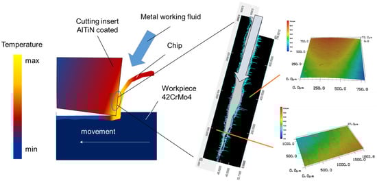
Figure 1.
Schematic representation of the machining process with cooling lubricant and secondary sliding zone between chip and cutting insert (chip–tool contact zone).
Gaining insight into the gap between the cutting tool and chip for a wet cutting processes is still challenging. Currently, there are no numerical models and methods for mapping and predicting the lubricant film thickness that can be used in the sense of a targeted design of the cooling lubricant supply. An approach is applying tribometer tests combined with high speed images of the real contact in cutting processes to conclude on the prevailing contact and lubrication conditions. For this purpose, experiments were first carried out on tribometers of two configurations, i.e., oscillating pin-on-plate and continuously pin-on-ring sliding. Further tests for film thickness measurement were carried out on an optical elasto-hydrodynamic lubrication (EHL) tribometer. For comparison, the influence of MWF on the chip formation process during metal cutting was investigated on a planing test rig (machine tool). This test rig allows high speed imaging and force measurements of an orthogonal cutting process using MWF. The first results show a reduced contact length between the chip and the tool as well as lower process forces for processes using MWF compared to dry cutting processes. The data obtained from the machining test will be compared with the results of the tribological test rigs.
The main objective of this work is to achieve a deeper understanding of the friction and lubrication regime between tool and workpiece in the secondary shear zone, such as whether MWF penetration and full film lubrication can be achieved. This is explored by comparing the CoF on tribometers and cutting test in both lubricated and dry conditions. In the tribometer test, a significant reduction in friction is shown in the presence of MWFs compared with dry tests. The film-forming ability of MWFs is also investigated on an optical rig. However, only a slight CoF variation can be seen in real cutting tests. This emphasizes the limited penetration of MWFs and the dominant role of boundary lubrication regime in chip–tool contact in wet cutting. Further effects known from tribology, such as boundary lubrication conditions or phase separation of water and oil, on machining are to be investigated.
2. Materials and Methods
2.1. Tribometers for Sliding Friction
In order to know the performance of the MWFs, common tribological tests were used as a first step. One of the tribological test rigs used was an oscillating pin-on-plate tribometer (Tribotechnic, 92110 Clichy, France, Milli Tribometer). In this setup, an AISI-4140+QT steel plate (42CrMo4+QT) (Ra = 0.4 µm) is in oscillating sliding motion against a fixed AlTiN-coated steel ball (diameter 6 mm, grade G28) under a defined load of 2 N, resulting in a Hertzian pressure of 830 MPa. The stroke length was 2 mm and the sliding velocity was 8 mm/s, the overall track length 15 m. The frictional force was recorded during the experiment. A commercial MFW (Blaser Vasco6000, Rüegsauschachen, Switzerland, 10% oil-in-water emulsion) in a heated tank was used as the lubricant, as shown in Figure 2a. The heated tank allowed to determine temperature effects on friction. The Blaser Vasco6000 concentrate was a water-miscible, boron-, formaldehyde- and chlorine-free MWF based on ester oil. Based on manufacturer information, the density was 0.99 g/cm3 at 20 °C and the viscosity was 42 mm2/s at 40 °C.
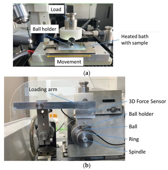
Figure 2.
Tribological test rigs: (a) setup for lubricated oscillating pin-on-plate tribometer and (b) lubricated pin-on-ring tribometer.
To determine the influence of MWF at high sliding speeds, the friction was also investigated using a pin-on-ring tribometer (modified on a Bühler Isomet 4000 linear precision saw as drive and a 3 axis force sensor), as shown in Figure 2b and presented in [30]. In the pin-on-ring arrangement, an AISI-4140+QT steel ring (diameter 37.5 mm, Ra = 200 nm) was used as the ring with a sliding speed of 784 mm/s, 1176 mm/s, and 1568 mm/s for 300 s (400 rpm, (track length 235.6 m), 600 rpm (track length 353.4 m), 800 rpm (track length 800 m)). An AlTiN-coated steel ball (chemical vapor deposition (CVD) coating, thickness 3 µm, grade G28) with a diameter of 6 mm was used as the pin. The pin was mounted on a 3D force sensor with a defined load to a Hertzian pressure of 1 GPa. The contact between the pin and the ring can be lubricated.
2.2. Tribometer for Film Thickness Measurement
The measurement of lubricant film thickness is an established method for lubricated rolling contacts. It allows conclusions to be drawn about the influence of oil additives and also of microstructures on bearing surfaces. The ball-on-disk test rig used for lubricant film thickness measurement is shown schematically in Figure 3. A highly polished steel ball is mounted against a glass disk (Ra = 10 nm) to form a circular high-pressure contact zone whose contact width and maximum contact pressure could be determined by the Hertzian dry contact theory. The disc is driven by a motor while the ball rolls, so that a pure rolling motion can be achieved. The MWF is continuously fed to the inlet section of the high pressure contact zone formed between the glass disk and the steel ball by means of a pump. In this work, all experiments were conducted under pure rolling conditions and the central film thickness in the contact center was measured at different entrainment/rolling speeds. The load on the ball is 30 N, resulting in a Hertzian pressure of 0.5 GPa and a contact semi-axis of 0.17 mm. A thin semi-reflective chromium layer (about 10 nm) was coated on the working/bottom surface of the glass disk, which helps enable high-contrast interference patterns. A dichromatic interferometry method [31] was used to measure the layer thickness with a red-green laser.
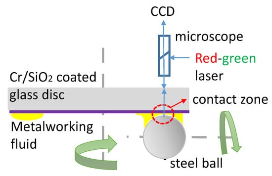
Figure 3.
The optical ball-on-disc test rig for lubricating film thickness measurement by optical interferometry.
2.3. Cutting Test
For the cutting experiments, a planing test rig (Figure 4), which was already used for high-speed recordings of dry cutting processes, was extended to wet cutting. To achieve high MWF pressures despite short process times <30 ms, the MWF is stored in an accumulator. The valve of the accumulator can be opened using a USB relay card. To protect the camera from the MWF, a sapphire glass is placed between the camera and the workpiece/tool. Additionally, the nozzle holder, as shown in Figure 4, protects the camera. In the cutting experiments, AISI4140+QT was machined using a TiAlN-coated cemented carbide tool (CVD coating, thickness 3 µm) with rake angle γ = 1° and flank angle α = 14°. A cutting speed of vc = 120 m/min, an uncut chip thickness of h = 0.1 mm, and uncut chip width of b = 2 mm were chosen in the experiments. The same MWF, Blaser Vasco6000 at 10%, was applied with pressure p = 10 bar tangentially to the rake face. The nozzle diameter was 1 mm and the distance from the nozzle outlet to the cutting edge was approximately 24 mm. Furthermore, a dry cutting process was carried out. Both processes were repeated once. High-speed images were recorded using a camera (Photron, 72764, Reutlingen, Germany, Fastcam SA5) and a light source of SMETec LED-P40. For the videos, a framerate of 20,000 fps, a shutter speed of 1/106,000 s, and 6× magnification were applied. Process forces were measured using a Kistler dynamometer (Type 9257B).
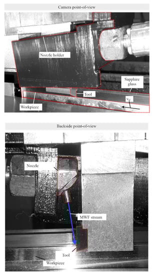
Figure 4.
The planing test rig for cutting experiments and the nozzle for MWF jetting.
3. Results
3.1. Frictional Tribometer Measurements
The tribological tests provide insight into the active lubrication regime and associated properties, ranging from the influence of MWF additives on the boundary lubrication regime to full film lubrication. It is assumed that both boundary lubrication and fully flooded conditions are encountered in the secondary sliding zone of machining processes. In the oscillating pin-on-plate setup, the unlubricated AlTiN-coated steel ball tested against the steel plate shows a CoF of about 0.6. When performing the test by applying MWF, the CoF could be reduced to 0.12, as shown in Figure 5. Heating the assembly did not significantly affect the friction, with evaporation of the media limiting the temperature. In the case of the pin-on-ring assembly, a dry CoF of up to 0.5 was achieved (Figure 6). The sliding speed did not influence the friction. For a lubricated contact, as shown in Figure 7, the CoF was reduced to ca. 0.15. From the results in Figure 7, it can be seen that increasing the sliding speed up to 1176 mm/s (600 rpm) has no significant effect on the friction. In case of the highest speed of 1568 mm/s (800 rpm), the CoF is slightly reduced. It can therefore be determined that the transition from boundary lubrication to full film lubrication between ball and ring could not be achieved.
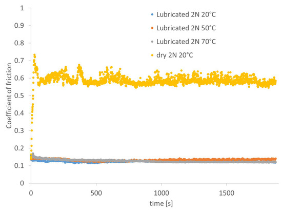
Figure 5.
Sliding friction results for lubricated oscillating pin-on-plate tribometer.
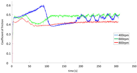
Figure 6.
Sliding friction results for unlubricated pin-on-ring tribometer.
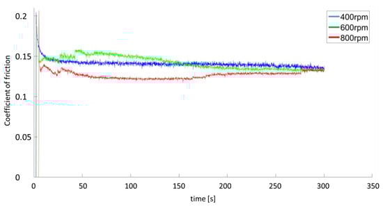
Figure 7.
Results of lubricated pin-on-ring tribometer at varied rotational speeds.
These differences may be caused by two effects. First, the friction on the pin-on-ring test rig is lower than that in the oscillating test rig due to the constant speed, where two reversal points can be found for the oscillating movement between the pin and the plate. The lubrication conditions at the reversal points may result in higher wear and friction, as the relative velocity is zero, resulting in mixed to solid friction. Secondly, the sliding speed of the pin-on-ring tribometer is higher, resulting in better hydrodynamic conditions.
3.2. Film Thickness Investigations
In order to gain a deeper insight into the penetration of MWF into the small gap of the secondary sliding zone between the chip and the cutting insert, measurements were taken for the film thickness formed in an EHL contact of a rolling ball and a disk under high pressure. Figure 8 shows the variation of the average film thickness with rolling speed for the commercial MWF used at a concentration of 10%. The film thickness results are plotted on a double logarithmic scale, since in classical EHL theory (using oil rather than emulsion), the central EHL film thickness increases linearly with increasing entrainment speeds on a log-log scale; see, for example, the curve of the reference base oil in Figure 8. As a Newtonian base oil, the slope is 0.68, which is consistent with the classical EHL lubrication theory [32], e.g., as predicted by the classical Hamrock–Dowson equation. In Figure 8, the theoretical results for the base oil are calculated using the Hamrock–Dowson equation with a viscosity of 58.8 mPas and a pressure-viscosity coefficient of 22 GPa−1 for the reference base oil at the experimental temperature.
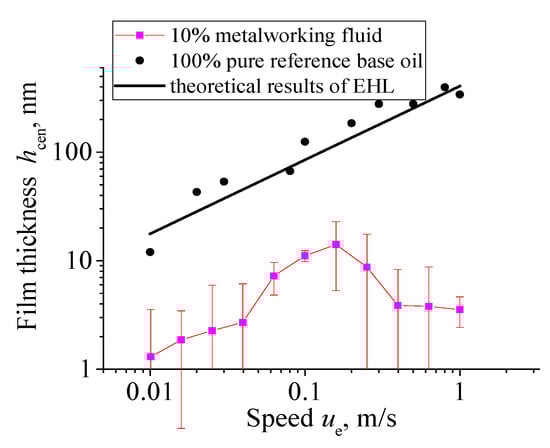
Figure 8.
Measured central film thickness at different rolling velocities for the commercial MWF at 10% concentration. The film behavior of a reference base oil is also shown as a reference. The theoretical results are calculated with the Hamrock–Dowson equation. (30 N, fully flooded).
In contrast to the base oil, the film thickness of MWF is always less than 20 nm at all tested velocities, as shown in Figure 8. The oil droplets in the emulsion are not trapped in the high-pressure zone to produce hydrodynamic lubrication. The contact zone may be surrounded by water droplets (as explained later in Figure 12 and shown schematically). The lubrication condition for the EHL contact with MWF may be considered as boundary lubrication rather than hydrodynamic fluid lubrication. Note that the film thickness is in the order of 10 nm, and additives in the commercial MWFs or other interfacial effects, e.g., wetting, surface tension, physical adsorption, and surface roughness, can affect such a thin lubricating film.
The film formation behavior in this case is quite different from homemade oil-in-water emulsions reported in the literature [28,29,33], where there are oil phase precipitates in the inlet region and therefore an EHL film can be formed. The reason for this difference might be the stability of the emulsion. The homemade emulsions are stable only for a short time (for only a few hours to several days). Cambiella et al. [33] reported the application of the concept of “controlled instability” of emulsions to let the oil droplets plate out and achieve good lubrication performance for rolling contacts. In contrast, the MWF emulsion used for cutting is stable over time, making it difficult for the oil droplets to separate. In addition, the cleaning function of MWF can re-emulsify any oil phase so that no hydrodynamic film could be formed [34].
3.3. Cutting Experiments
To compare the measurements with a realistic cutting process, tests were carried out on a planing test rig. Particle image velocimetry (PIV) investigations were carried out for the process. This allows the chip flow to be studied in detail, as shown in Figure 9. On the flank between the chip and the cutting tool above the separation point, the material velocity moves at less than ¼ of the cutting velocity vc. In addition, there is a defined separation point. The part above the separation point is removed from the workpiece as a chip and the part below the separation point is pressed onto the cutting edge. The contact is pressurized and might be difficult for the MWF to penetrate.
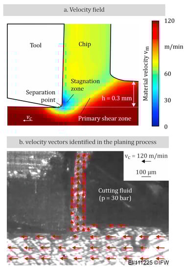
Figure 9.
High-speed investigation of the cutting process based on particle image velocimetry (PIV): (a) velocity field; (b) PIV image.
The results of the cutting tests are shown in Figure 10. The MWF supply starts shortly before the cutting process begins (Figure 10a). The MWF flows tangentially along the rake face of the tool to the workpiece. During initial chip formation (Figure 10b), a film of MWF forms on the surface of the workpiece. This film is pushed in front of the chip during the process. It can also be seen that the MWF is transported out of the gap between the chip and the rake face in the contact zone. After the initial chip formation, a stationary chip-forming process is achieved where no MWF is visible between the rake face and the chip, see Figure 10c. It can therefore be assumed that the lubrication effect is small. Better penetration of MWF between the chip and rake face could be achieved with higher MWF pressures. The process forces, Fi, and the contact lengths, cl, between the chip and rake face for dry processes and processes with MWF are shown in Figure 10d. When applying MWF with a pressure p = 10 bar, the contact lengths between the chip and rake face decrease. This is mainly due to the mechanical load of the MWF acting on the rake face, which presses the chip against the workpiece and reduces the contact length. In this case, the chip acts as a bending beam. Due to the low chip thickness, this bending beam has a small area moment of inertia and the forces of the MWF due to the dynamic pressure of 10 bar are sufficient to change the contact length. This effect is described in more detail in [35]. In addition, lower temperatures in the wet process, confirmed by the avoidance of annealing colors on the chip, could lead to different residual stresses in the chip and thus to a different chip shape and contact length.
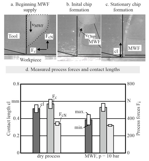
Figure 10.
(a) High-speed images at the beginning of MWF supply but no chip formation, (b) the beginning of chip formation and (c) the stationary chip formation. (d) Experimental results of process forces and contact lengths. (Fc is the cutting force which acts in the direction of the cutting speed vc. FcN acts normal to the direction of the cutting speed.).
The process forces also decrease when using MWFs. This is the result of the reduced contact lengths and therefore the reduced loads acting on the rake face. It also has to be considered that the thermal softening of the material is stronger for the dry process. However, since the process forces of the wet process are lower, the reduced contact length might be the most important effect.
To conclude the topic of the tribological boundary films formation, a piece of chip was investigated by time-of-flight secondary mass spectrometry (ToF-SIMS). A description of the method can be found in [36,37]. For this, the cutting insert was suspended into the MWF; afterward, the cutting test was performed. The resulting chip surface was investigated. An increased intensity of sulfur and NaOH+ could be detected, resulting from the MWF, see Figure 11. However, to determine whether the tribofilms have already formed in the chip–tool contact zone, ToF-SIMS analysis should also be applied to the tool surface in future study. Here, it shows the possibility to apply this technique for this field.
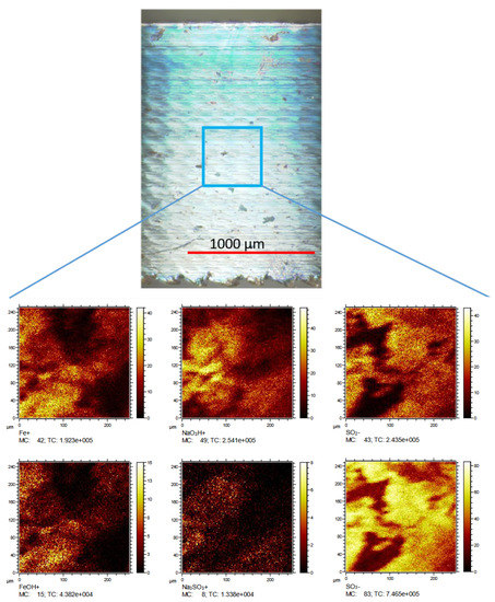
Figure 11.
ToF-SIMS investigation on chip surface, proving sulfur and NaOH+; a brighter color indicates increased signal intensity on surface.
4. Discussion
Compared to the dry frictional results on the pin-on-ring and pin-on-plate tribometers, the sliding friction with MWF is drastically reduced (five to six times smaller). While dry friction has a CoF value of 0.6, the CoF of MWF-lubricated contacts could be reduced to 0.1. Increasing the rotational speed in the pin-on-ring tests did not further reduce the friction. It can be understood that the sliding contact still works under boundary lubrication conditions, which are influenced by the layers formed on the surface by the additives. This is confirmed by the film thickness results with the optical ball-on-disc measurements, which show that there is no hydrodynamic film-formation capability for the MWFs used. The oil droplets in the MWF cannot plate out to form an inlet oil pool and consequently an effective film because the droplets are held in emulsion [34]. Figure 12 illustrates the effect of keeping oil out of contact; for example, the additives and adsorbed molecules remain attached to the surfaces to reduce friction for the two tribometers mentioned above.
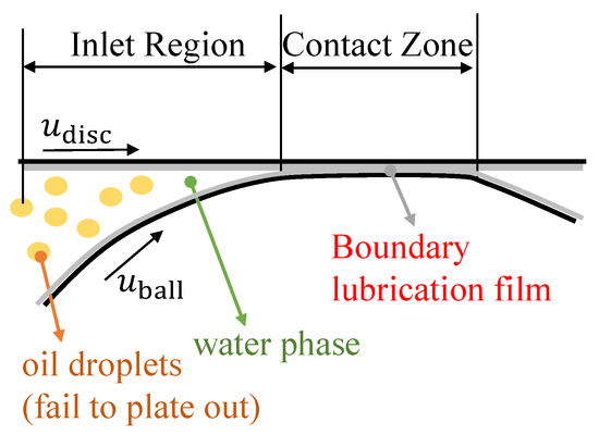
Figure 12.
Boundary film lubrication of MWF in highly loaded contact. No elasto-hydrodynamic film can be formed because the oil droplets in the emulsion fail to plate out in the inlet region of the tribological contact [34]. Reprinted/adapted with permission from Ref. [34]. Copyright year 2023, copyright owner IMKT.
Therefore, additives such as sulfur and phosphorus bind on the surface and protect against high friction under extreme pressures. It has to be regarded that sulfur-based tribofilms form under high temperatures, as can be found close to the cutting zone of the chip–tool contact. The boundary film formation could be proven by ToF-SIMS measurements on the chip surface from a cutting experiment. However, whether the MWF can penetrate the secondary sliding zone between the cutting insert and the chip is still largely unknown. This question may be answered by measuring the chemical elements on the tool surface as well in future study. Special attention should be given to avoid any contamination of the MWF out of the contact zone after the cutting experiments, which makes this experiment challenging.
In the current cutting experiments, the reduced cutting force in the presence of MWF is mainly attributed to the reduced contact length of the chip–tool contact. Note that the CoF for cutting experiments can be obtained by the ratio of the two process forces FcN and Fc, and the consideration of the process forces before the beginning chip formation Fch,min and FcN,hmin [35,38]:
where is the rake angle. As a result, the CoF for dry cutting is 0.48, while for wet cutting, it is 0.47. These two values are much larger than the CoF with MWF measured on the two tribometers, but they are smaller than the dry sliding CoF. From this comparison, it may be known that the MWF or molecules in the MWF could only penetrate partly into the chip–tool contact zone. Here, the surface roughness and adhesive forces of the cutting tool and the chip have to be regarded and will be used as input in a fluid–structure interaction simulation. The investigation of the MWF penetration depth into the contact has to be researched in terms of analytical approaches such as ToF-SIMS measurements combined with simulation and aligned to cutting tests.
5. Conclusions
In order to investigate the lubrication mechanisms between the chip and the tool in the secondary shear zone, tribological methods were used and compared with real cutting tests. The importance of boundary lubrication was highlighted:
- It could be demonstrated by tribometer experiments under sliding conditions that MWFs can significantly reduce the CoF compared to dry conditions, i.e., from CoF of 0.6 to 0.12.
- The condition of boundary lubrication was demonstrated by measuring the film formation properties and film thicknesses of MWF on an optical ball-on-disc test rig using interferometry. In the case of a rolling point contact on the optical film thickness test rig, no hydrodynamic film could be built by commercial MWF mixed with water. The lubrication status in the commercial emulsions can be considered as boundary lubrication but not hydrodynamic fluid lubrication. The boundary films formed by additives of the MWF may result in the friction reduction in the sliding tests. To reduce the friction in the secondary sliding zone of the cutting insert–chip contact, the penetration of MWF has to be ensured.
- The first test of the real cutting tests on the planing test rig showed that the current setup has insufficient pressure to achieve beneficial effects with the MWF. Higher jetting pressures and modified nozzle positions will be conducted in further studies.
In the case of boundary lubrication, the coefficient of friction is highly influenced by the shear properties of the tribolayer interface as a result of physiochemical adsorption and reaction between molecules in the lubricants with the rubbing surfaces, and it is largely independent of the viscosity of the lubricant. According to the manufacturer, extreme pressure and anti-wear additives are used for the MWFs applied, which could also be detected on the chip surface. The results from the pin-on-ring tribometer tests can be confirmed, according to which, the reduction in friction when using MWF emulsion occurs in particular through tribological layers. To gain further insights, ToF-SIMS studies have to be performed to conclude on the formed boundary film and the temperature that led to specific film compositions. The feasibility could be proven by initial investigation.
To improve the cutting process, a modified cutting insert by surface structuring may be designed to increase the possibility of MWF penetration in the secondary sliding zone. It is expected that the MWF will reduce the friction of the process significantly if entrainment into the sliding zone is made possible.
Author Contributions
Conceptualization, F.P. and L.E.; methodology, F.P.; investigation, F.P., H.L. and L.E.; data curation, F.P., H.L. and L.E.; writing—original draft preparation, F.P. and L.E.; writing—review and editing, all; supervision, G.P. and B.D.; funding acquisition, G.P. and B.D. All authors have read and agreed to the published version of the manuscript.
Funding
The authors appreciate the funding of this work within the Priority Program 2231 “Efficient cooling, lubrication and transportation—coupled mechanical and fluid-dynamical simulation methods for efficient production processes (FLUSIMPRO)” by the German Research Foundation (DFG)—project number 439904924. The publication of this article was funded by the Open Access Fund of Leibniz Universität Hannover.
Data Availability Statement
The datasets of the study can be requested from the author.
Conflicts of Interest
The authors declare no conflict of interest. The funders had no role in the design of the study; in the collection, analyses, or interpretation of data; in the writing of the manuscript, or in the decision to publish the results.
References
- Brinksmeier, E.; Meyer, D.; Huesmann-Cordes, A.; Herrmann, C. Metalworking fluids—Mechanisms and performance. CIRP Ann. 2015, 64, 605–628. [Google Scholar] [CrossRef]
- Osama, M.; Singh, A.; Walvekar, R.; Khalid, M.; Gupta, T.C.S.M.; Yin, W.W. Recent developments and performance review of metal working fluids. Tribol. Int. 2017, 114, 389–401. [Google Scholar] [CrossRef]
- Sangermann, H. Hochdruck-Kühlschmierstoffzufuhr in der Zerspanung. Ph.D. Thesis, RWTH Aachen University, Aachen, Germany, 2013. [Google Scholar]
- Astakhov, V.P.; Joksch, S. (Eds.) Metalworking Fluids (MWFs) for Cutting and Grinding: Fundamentals and Recent Advances; Elsevier: Amsterdam, The Netherlands, 2012. [Google Scholar]
- Yoshimura, H.; Itoigawa, F.; Nakamura, T.; Niwa, K. Development of Nozzle System for Oil-on-Water Droplet Metalworking Fluid and Its Application to Practical Production Line. JSME Int. J. Ser. C Mech. Syst. Mach. Elem. Manuf. 2005, 48, 723–729. [Google Scholar] [CrossRef]
- Klocke, F.; Krämer, A.; Sangermann, H.; Lung, D. Thermo-Mechanical Tool Load during High Performance Cutting of Hard-to-Cut Materials. Procedia CIRP 2012, 1, 295–300. [Google Scholar] [CrossRef]
- Soković, M.; Mijanović, K. Ecological aspects of the cutting fluids and its influence on quantifiable parameters of the cutting processes. J. Mater. Process. Technol. 2001, 109, 181–189. [Google Scholar] [CrossRef]
- Rahim, E.; Ibrahim, M.; Aziz, S.; Mohid, Z. Experimental Investigation of Minimum Quantity Lubrication (MQL) as a Sustainable Cooling Technique. Procedia CIRP 2015, 26, 351–354. [Google Scholar] [CrossRef]
- Sharma, A.K.; Tiwari, A.K.; Dixit, A.R. Effects of Minimum Quantity Lubrication (MQL) in machining processes using conventional and nanofluid based cutting fluids: A comprehensive review. J. Clean. Prod. 2016, 127, 1–18. [Google Scholar] [CrossRef]
- Yanbin, Z.; Hao, L.N.; Changhe, L.; Chuanzhen, H.; Hafiz, M.A.; Xuefeng, X.; Cong, M.; Wenfeng, D.; Xin, C.; Min, Y.; et al. Nano-enhanced biolubricant in sustainable manufacturing: From processability to mechanisms. Friction 2022, 10, 803–841. [Google Scholar]
- Safie, N.S.S.; Murad, M.N.; Lih, T.C.; Azmi, A.I.; Hamzah, W.A.W.; Danish, M. Roles of Eco-Friendly Non-Edible Vegetable Oils in Drilling Inconel 718 through Minimum Quantity Lubrication. Lubricants 2022, 10, 211. [Google Scholar] [CrossRef]
- Carvalho, D.O.A.; da Silva, L.R.R.; de Souza, F.C.R.; França, P.H.P.; Machado, R.; Costa, E.S.; Fernandes, G.H.N.; da Silva, R.B. Flooding Application of Vegetable- and Mineral-Based Cutting Fluids in Turning of AISI 1050 Steel. Lubricants 2022, 10, 309. [Google Scholar] [CrossRef]
- Rech, J.; Arrazola, P.; Claudin, C.; Courbon, C.; Pusavec, F.; Kopac, J. Characterisation of friction and heat partition coefficients at the tool-work material interface in cutting. CIRP Ann. 2013, 62, 79–82. [Google Scholar] [CrossRef]
- Lakner, T.; Hardt, M. A Novel Experimental Test Bench to Investigate the Effects of Cutting Fluids on the Frictional Conditions in Metal Cutting. J. Manuf. Mater. Process. 2020, 4, 45. [Google Scholar] [CrossRef]
- Norm DIN 51385; Schmierstoffe—Bearbeitungsmedien für die Umformung und Zerspanung von Werkstoffen—Begriffe. Beuth Verlag: Berlin, Germany, 2013.
- Kajdas, C. Additives for metalworking lubricants-a review. Lubr. Sci. 1989, 1, 385–409. [Google Scholar] [CrossRef]
- Zhang, F.; Fillot, N.; Bouscharain, N.; Devaux, N.; Philippon, D.; Matta, C.; Morales-Espejel, G. Water droplets in oil at the inlet of an EHD contact: A dual experimental and numerical investigation. Tribol. Int. 2023, 177, 108015. [Google Scholar] [CrossRef]
- Lim, S.K.; Azmi, W.H.; Jamaludin, A.S.; Yusoff, A.R. Characteristics of Hybrid Nanolubricants for MQL Cooling Lubrication Machining Application. Lubricants 2022, 10, 350. [Google Scholar] [CrossRef]
- Ma, J.; Gali, O.A.; Riahi, R.A. An Evaluation of the Tribological Behavior of Cutting Fluid Additives on Aluminum-Manganese Alloys. Lubricants 2021, 9, 84. [Google Scholar] [CrossRef]
- Canter, N. Special Report: Trends in extreme pressure additives. Tribol. Lubr. Technol. 2007, 63, 10. [Google Scholar]
- Brinksmeier, E.; Walter, A. Generation of Reaction Layers on Machined Surfaces. CIRP Ann. 2000, 49, 435–438. [Google Scholar] [CrossRef]
- Schulz, J.; Brinksmeier, E.; Meyer, D. On the Interactions of Additives in Metalworking Fluids with Metal Surfaces. Lubricants 2013, 1, 75–94. [Google Scholar] [CrossRef]
- Furlong, O.; Miller, B.; Kotvis, P.; Adams, H.; Tysoe, W.T. Shear and thermal effects in boundary film formation during sliding. RSC Adv. 2014, 4, 24059–24066. [Google Scholar] [CrossRef]
- Pape, F.; Muhmann, C.; Pahl, D.; Lipinsky, D.; Arlinghaus, H.F.; Poll, G. ZDDP Containing Tribofilms Generated under Sliding Micro Contact and Bearing Test Rig Conditions. Mater. Perform. Charact. 2018, 7, 191–212. [Google Scholar] [CrossRef]
- Gatzen, M.; Pape, F.; Bruening, C.; Gatzen, H.; Arlinghaus, H.; Poll, G. Correlation between performance and boundary layers in high speed bearings lubricated with polymer-enhanced greases. Tribol. Int. 2010, 43, 981–989. [Google Scholar] [CrossRef]
- Pape, F. Mikrotribologische Untersuchungen an Wälzlagern mit Polymeradditivierter Fettschmierung. PhD. Thesis, Leibniz University Hanover, PZH, Produktionstechnisches Zentrum, Garbsen, Germany, 2011. [Google Scholar]
- Britt, L.G.; Jenke, P.K.; Lipinsky, D.; Arlinghaus, H.F. ToF-SIMS investigation of tribochemical surface reaction films built up by specially added cooling lubricants. J. Vac. Sci. Technol. B Nanotechnol. Microelectron. Mater. Process. Meas. Phenom. 2018, 36, 03F120. [Google Scholar] [CrossRef]
- Ma, L.; Zhang, C.; Luo, J. Investigation of the film formation mechanism of oil-in-water (O/W) emulsions. Soft Matter 2011, 7, 4207–4213. [Google Scholar] [CrossRef]
- Liang, H.; Guo, D.; Ma, L.; Luo, J. Investigation of film formation mechanism of oil-in-water (O/W) emulsions at high speeds. Tribol. Int. 2017, 109, 428–434. [Google Scholar] [CrossRef]
- Pape, F.; Liu, H.C.; Ellersiek, L.; Krödel, A.; Denkena, B.; Poll, G. Influence of Metal Working Fluids in Cutting Processes. Defect Diffus. Forum 2022, 414, 51–57. [Google Scholar] [CrossRef]
- Liu, H.C.; Guo, F.; Guo, L.; Wong, P.L. A dichromatic interference intensity modulation approach to measurement of lubricating film thickness. Tribol. Lett. 2015, 58, 15. [Google Scholar] [CrossRef]
- Greenwood, J.A. Elastohydrodynamic lubrication. Lubricants 2020, 8, 51. [Google Scholar] [CrossRef]
- Cambiella, A.; Benito, J.M.; Pazos, C.; Coca, J.; Ratoi, M.; Spikes, H.A. The effect of emulsifier concentration on the lubricating properties of oil-in-water emulsions. Tribol. Lett. 2006, 22, 53–65. [Google Scholar] [CrossRef]
- Liu, H.C.; Pape, F.; Zhao, Y.; Ellersiek, L.; Denkena, B.; Poll, G. On the Elastohydrodynamic Film-Forming Properties of Metalworking Fluids and Oil-in-Water Emulsions. Tribol. Lett. 2003, 71, 10. [Google Scholar] [CrossRef]
- Denkena, B.; Krödel, A.; Ellersiek, L. Influence of metal working fluid on chip formation and mechanical loads in orthogonal cutting. Int. J. Adv. Manuf. Technol. 2021, 118, 3005–3013. [Google Scholar] [CrossRef]
- Pape, F.; Möbes, G.; Lipinsky, D.; Muhmann, C.; Arlinghaus, H.F.; Poll, G.; Mori, S. Investigation of the temperature influence on the formation of boundary layers on bearings. Tribol. Schmier. 2017, 64, 39–46. [Google Scholar]
- Pape, F.; Terwey, J.T.; Wiesker, S.; Averbeck, S.; Muhmann, C.; Lipinsky, D.; Arlinghaus, H.F.; Kerscher, E.; Sauer, B.; Poll, G. Tribological research on the development of White Etching Cracks (WECs). Forsch. Ingenieurwesen 2018, 82, 341–352. [Google Scholar] [CrossRef]
- Merchant, M.E. Mechanics of the Metal Cutting Process. I. Orthogonal Cutting and a Type 2 Chip. J. Appl. Phys. 1945, 16, 267–275. [Google Scholar] [CrossRef]
Disclaimer/Publisher’s Note: The statements, opinions and data contained in all publications are solely those of the individual author(s) and contributor(s) and not of MDPI and/or the editor(s). MDPI and/or the editor(s) disclaim responsibility for any injury to people or property resulting from any ideas, methods, instructions or products referred to in the content. |
© 2023 by the authors. Licensee MDPI, Basel, Switzerland. This article is an open access article distributed under the terms and conditions of the Creative Commons Attribution (CC BY) license (https://creativecommons.org/licenses/by/4.0/).