Wear Mechanisms in Press Hardening: An Analysis through Comparison of Tribological Tests and Industrial Tools

 , , , ,
  and
and 
Abstract
1. Introduction
2. Materials and Methods
2.1. Materials
2.2. Evaluation of Coating Mechanical Properties
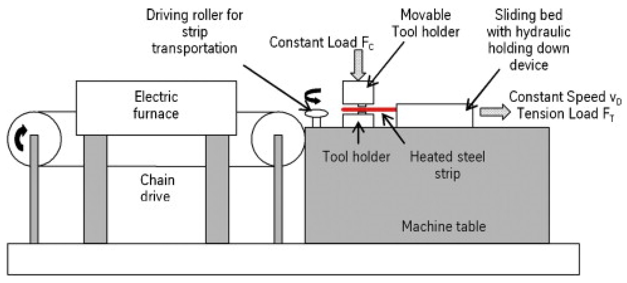
2.3. Strip Drawing Tests
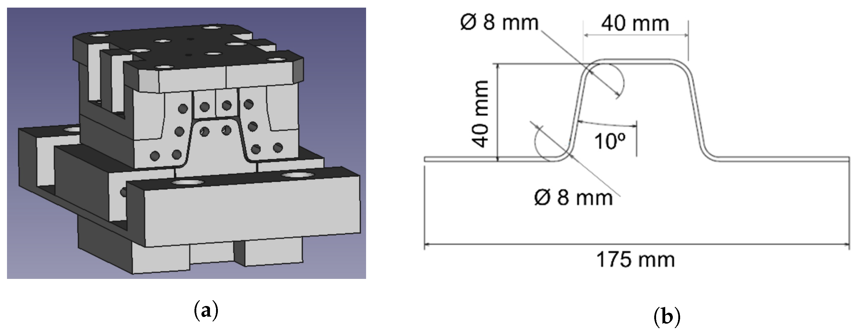
2.4. Pilot Environment: Hot Stamping of Omega Components
2.5. Study of Industrial Tools
Surface Replication
3. Results
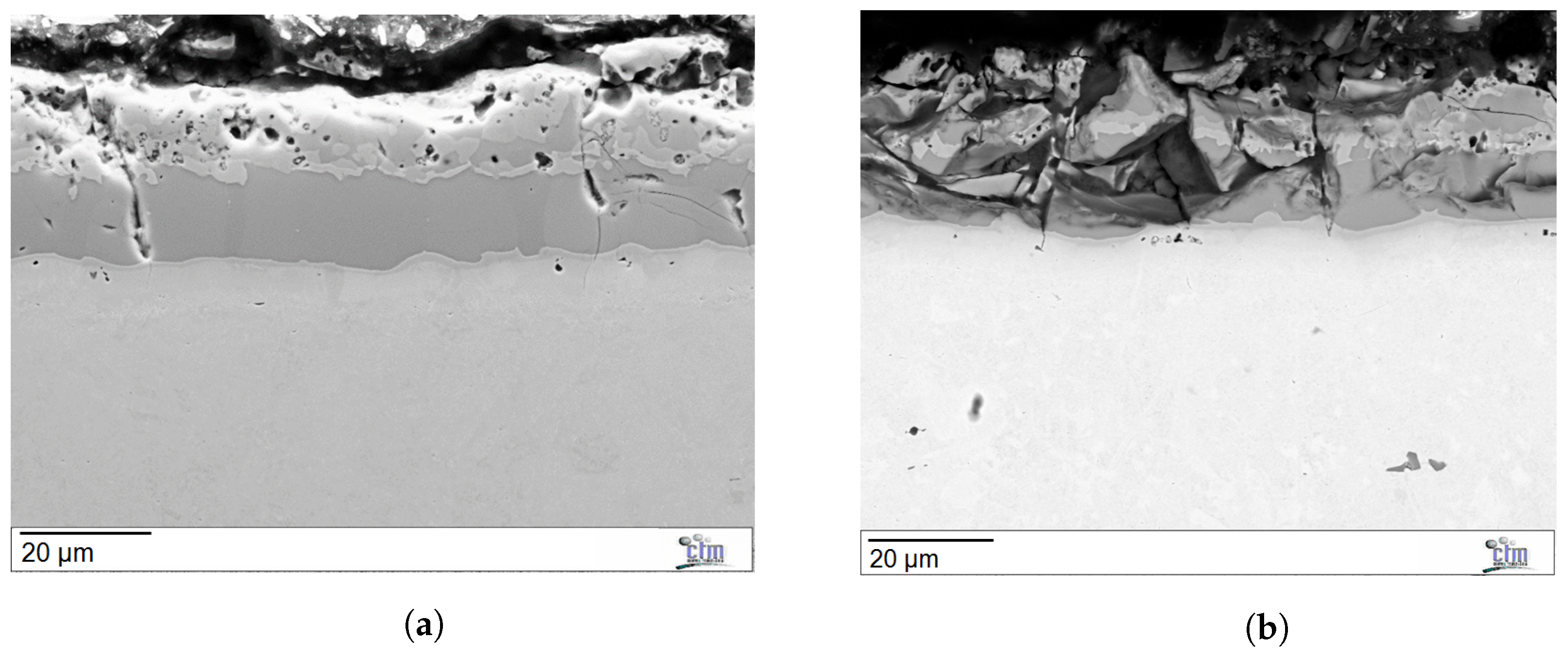
3.1. Properties of the Al-Si Coating
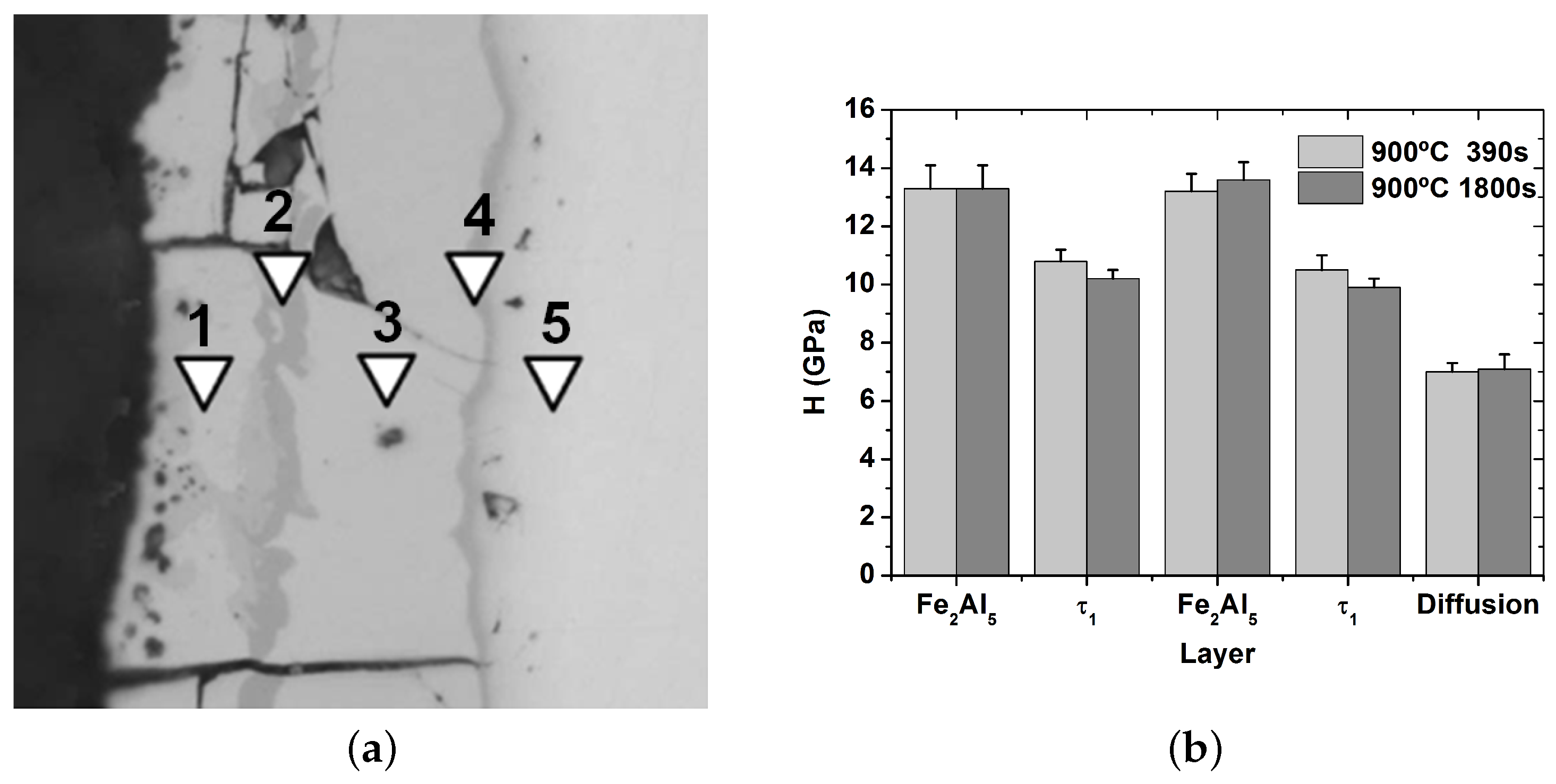
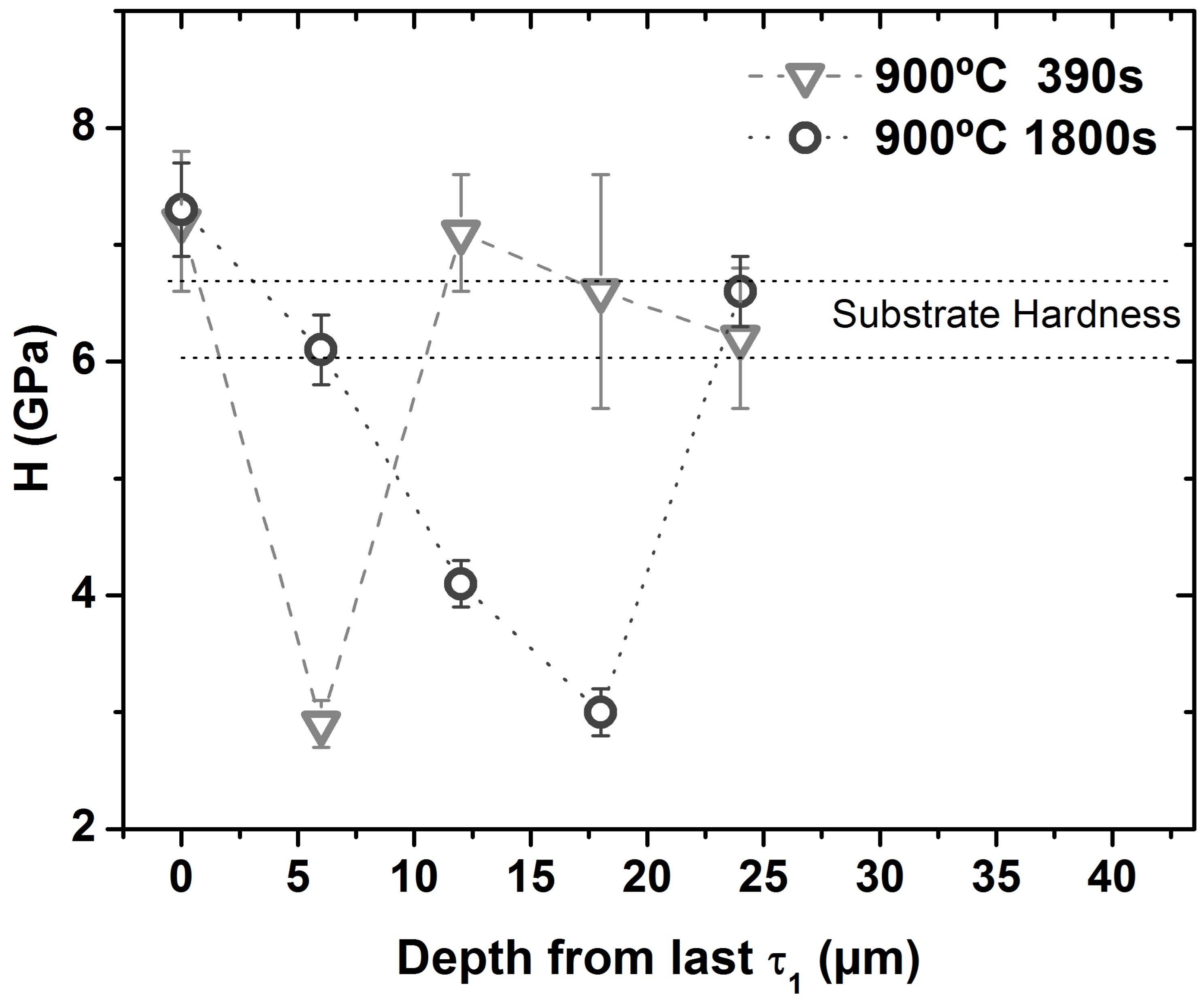
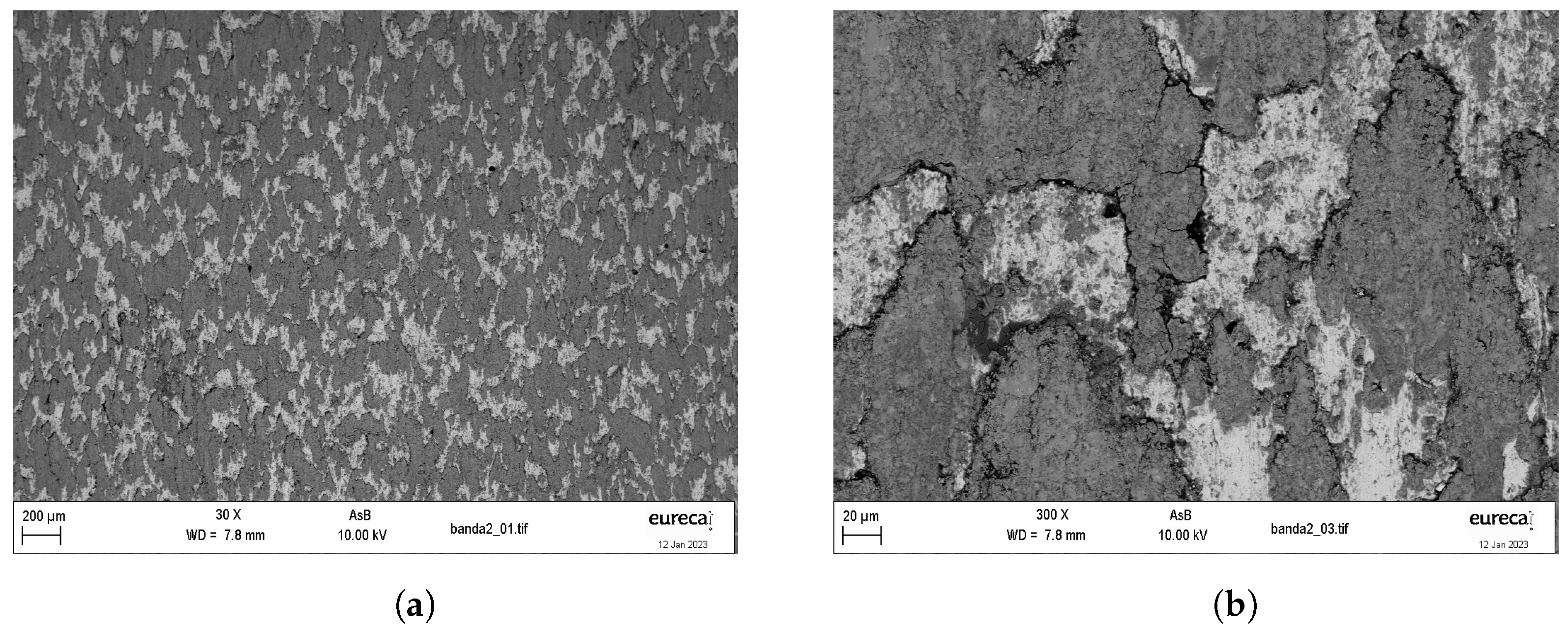
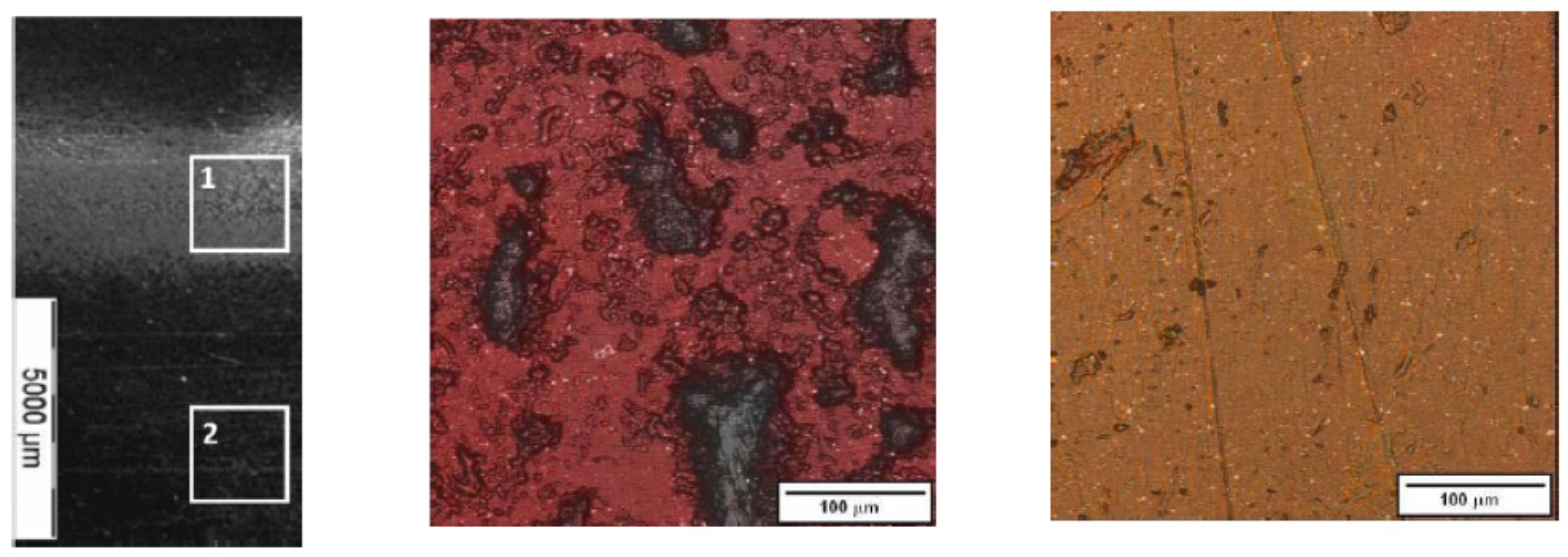
3.1.1. Micromechanical Analysis of the Coating
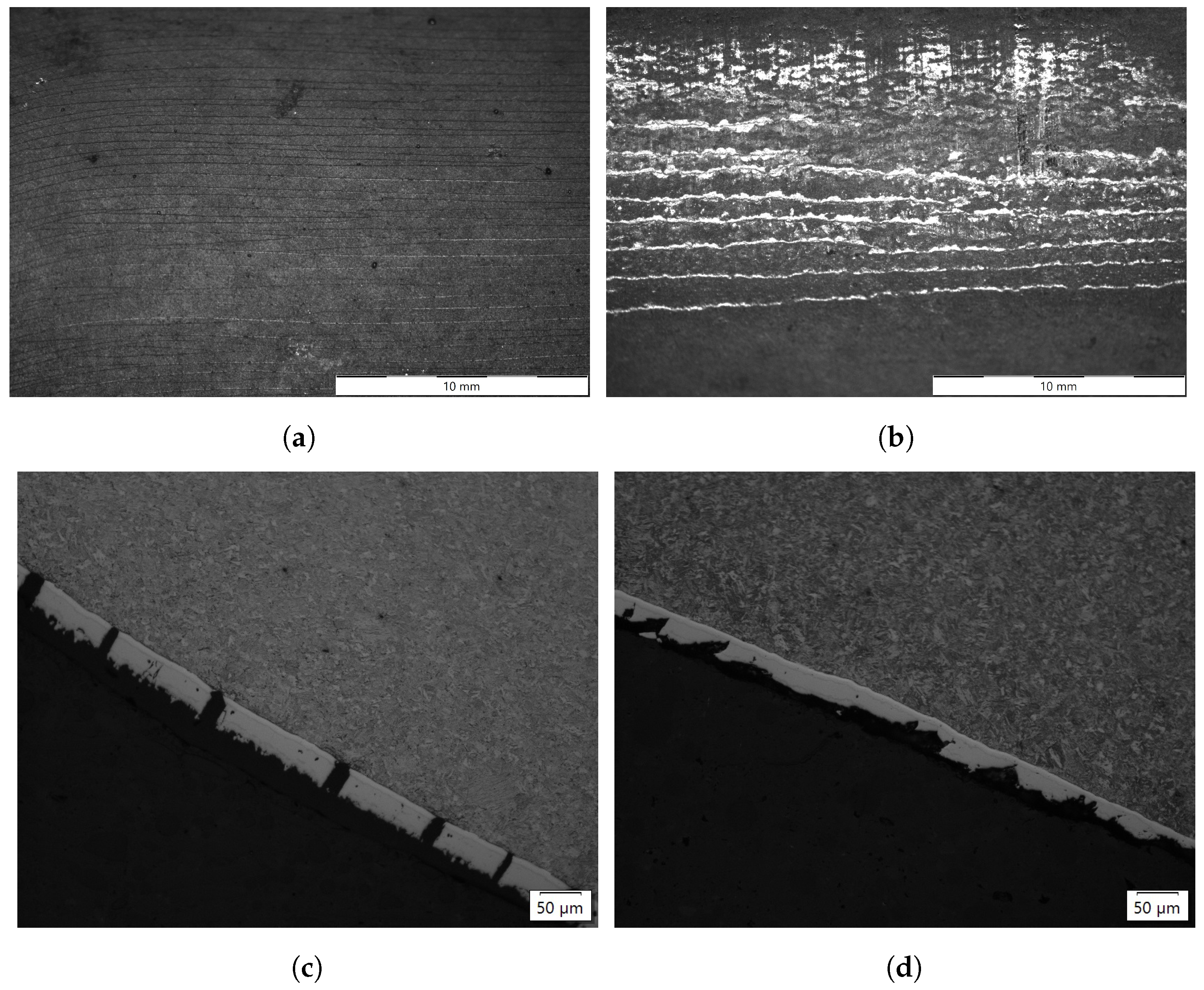
3.1.2. Failure of the Coating during Forming
4. Wear Mechanisms on Press Hardening Environments
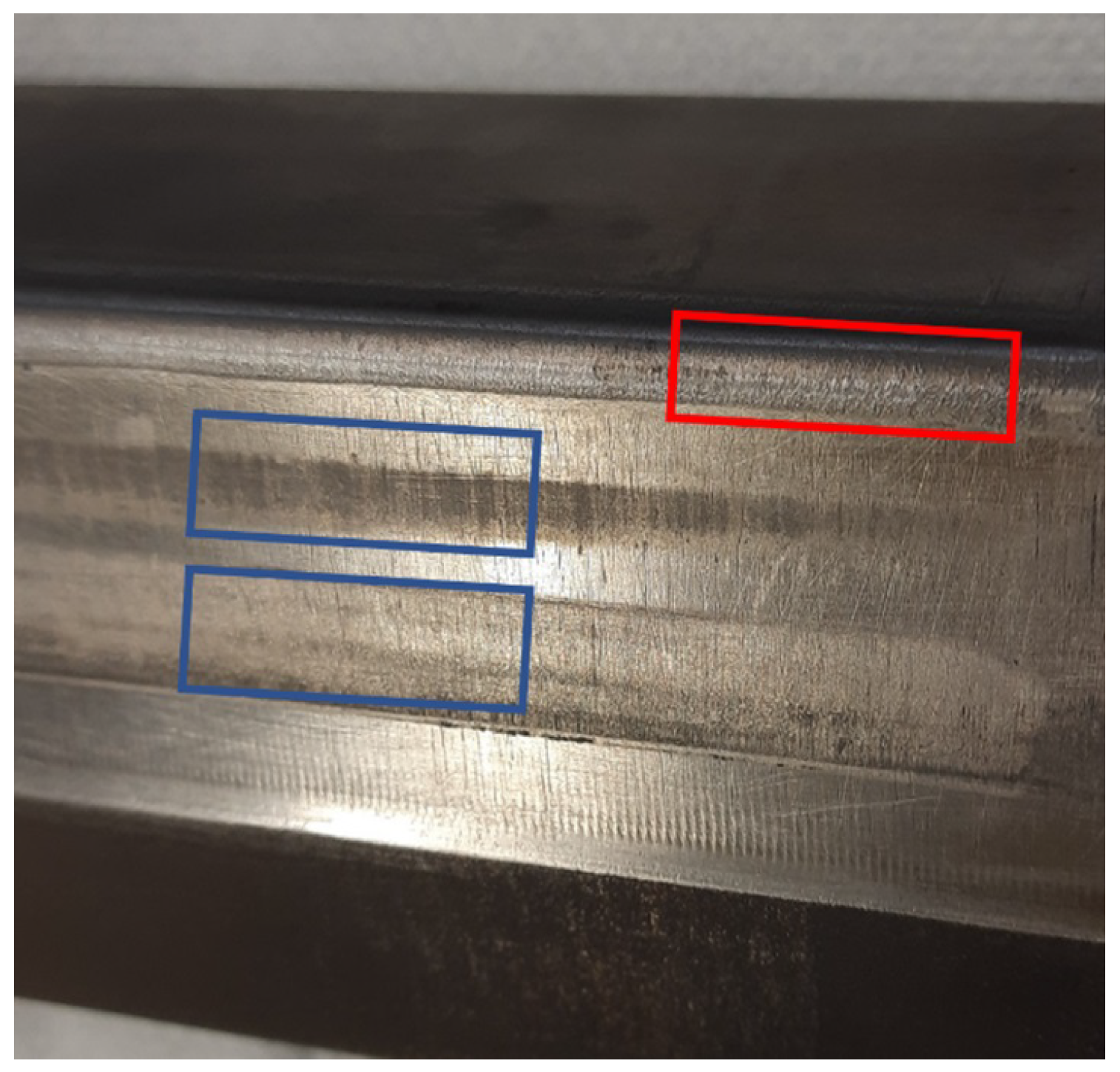
4.1. Wear on Strip Drawing Inserts
4.2. Wear on Pilot Environment Inserts
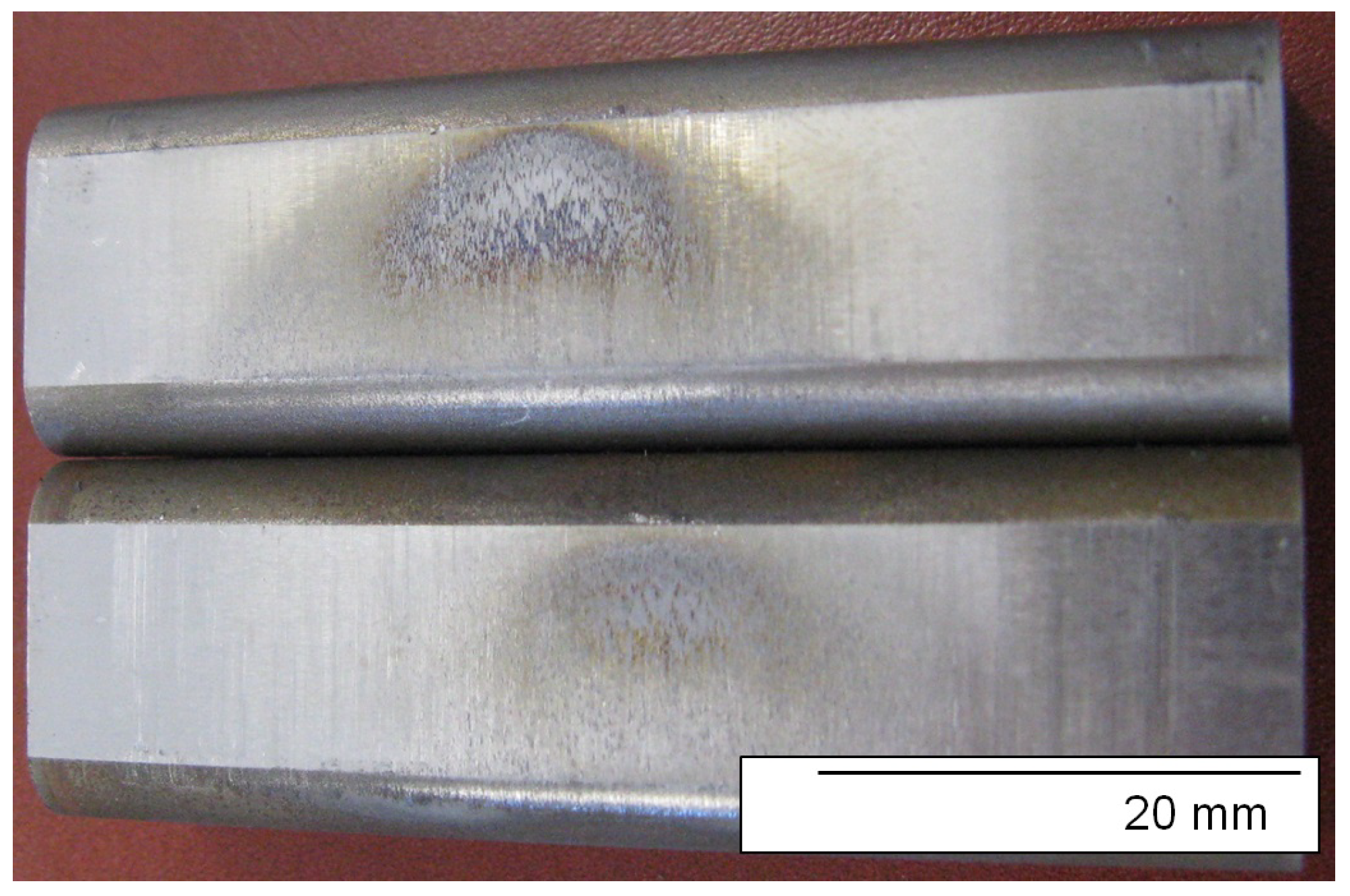
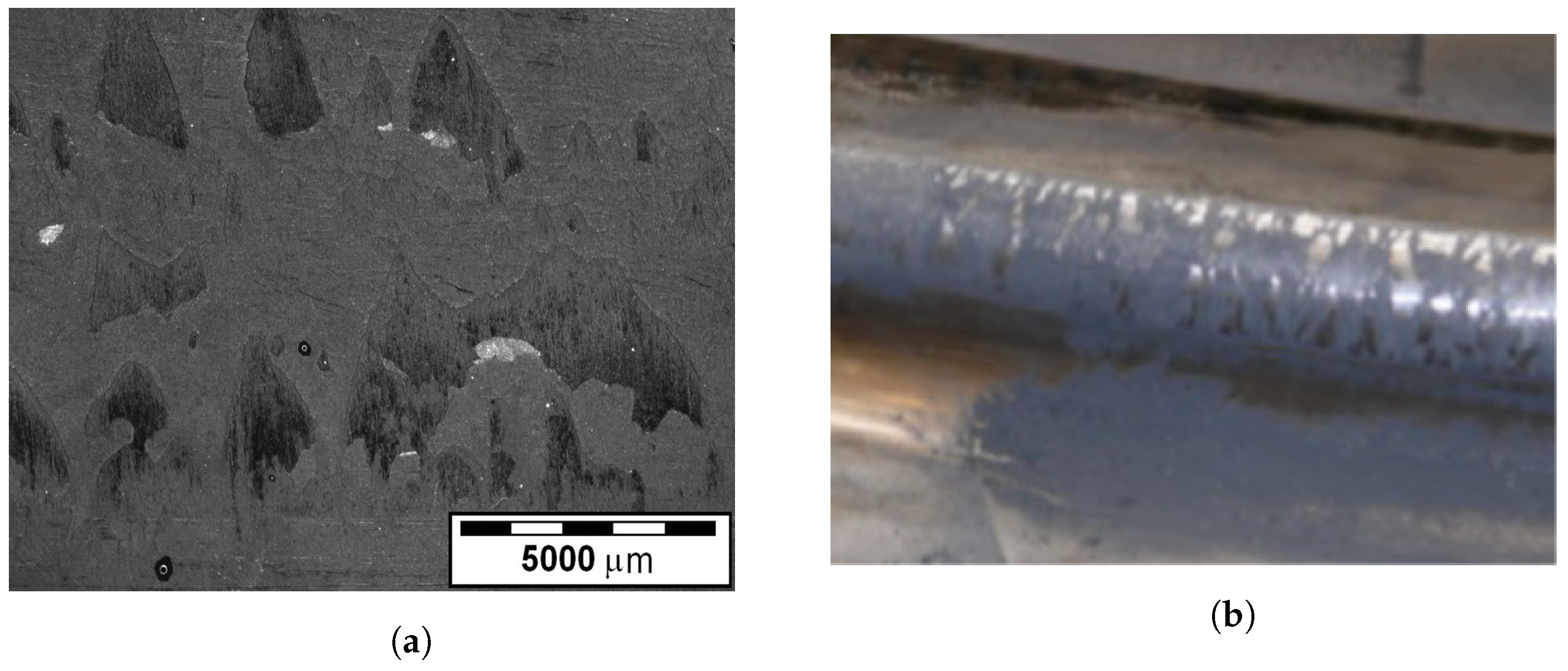
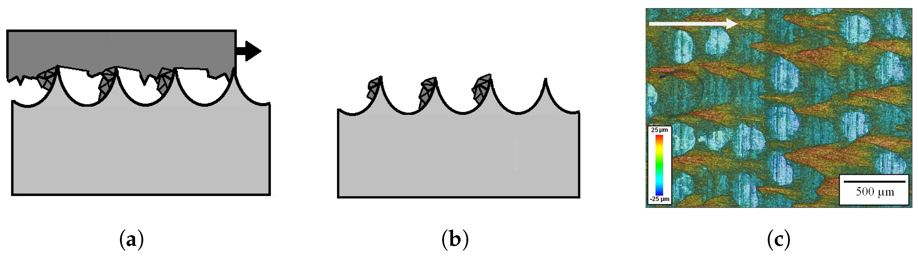
4.2.1. Gross Material Transfer
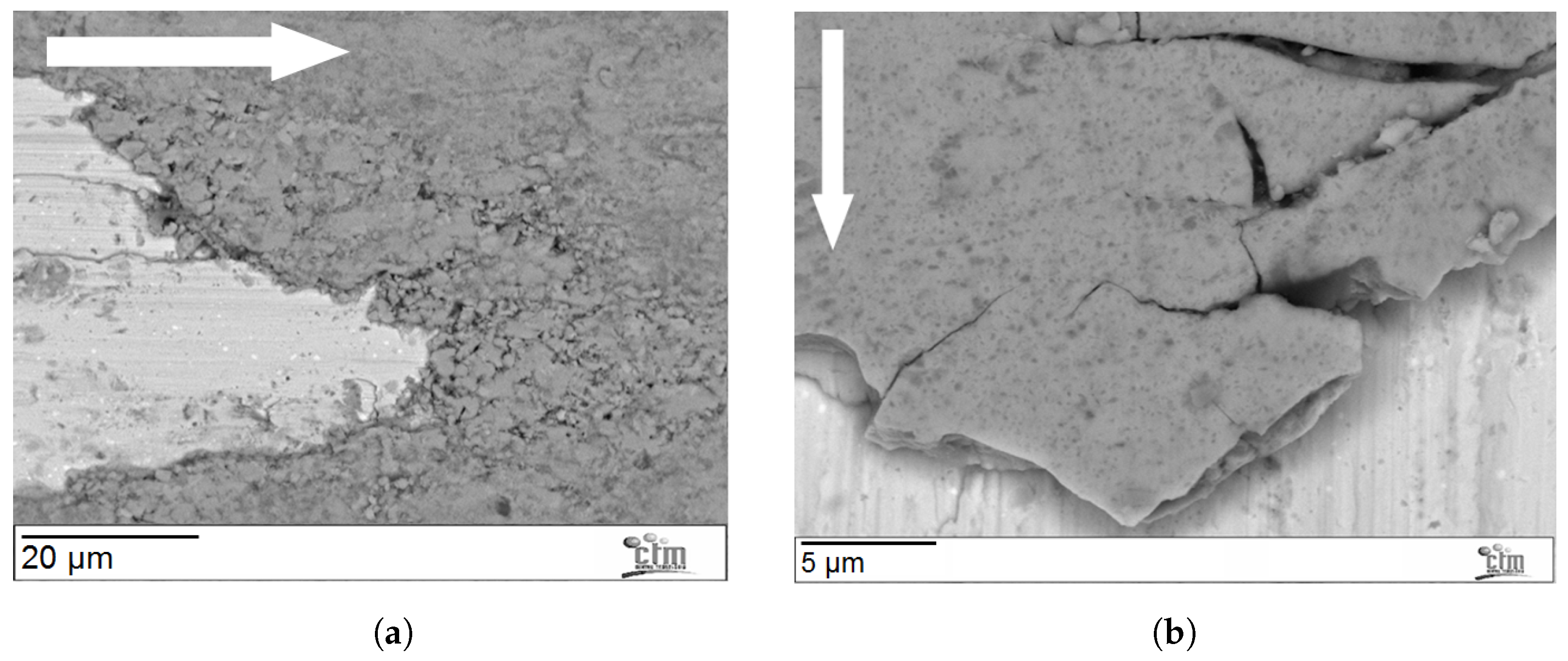
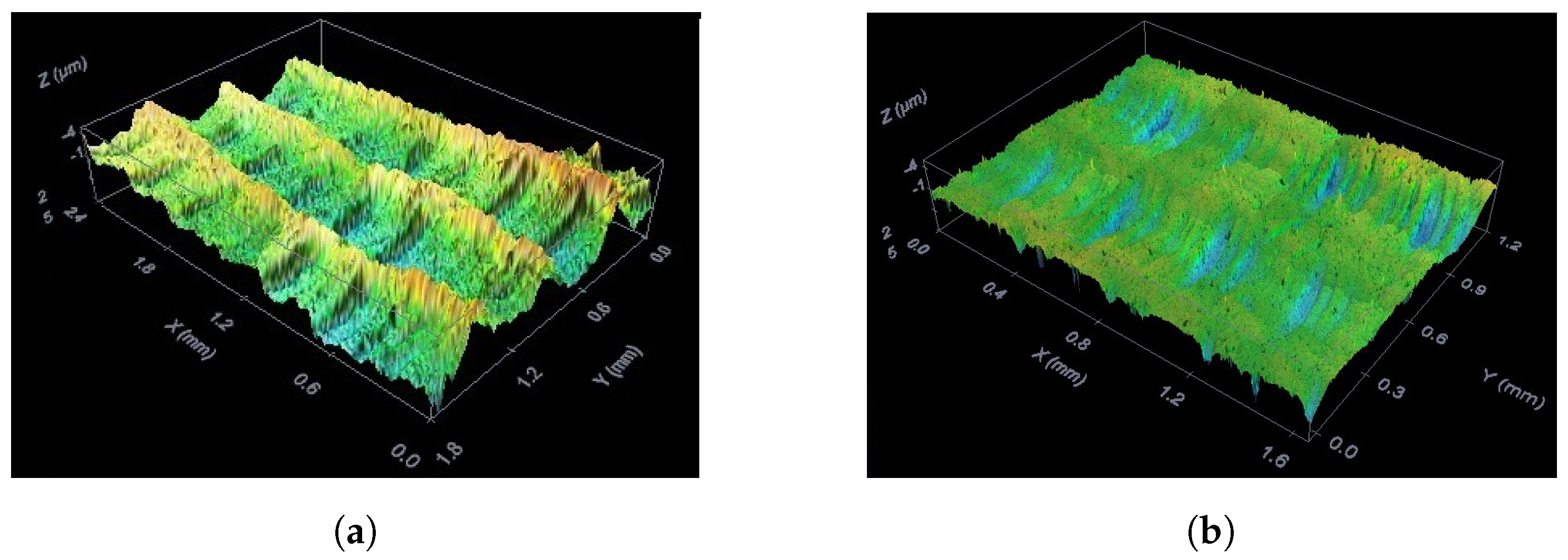
4.2.2. Abrasive Wear and Plastic Damage
4.2.3. Combined Wear and Sparse Material Transfer
4.3. Wear on Industrial Tools
4.3.1. Gross Material Transfer on Industrial Tools
4.3.2. Abrasive Wear and Mechanical Damage
4.3.3. Combined Wear and Sparse Material Transfer
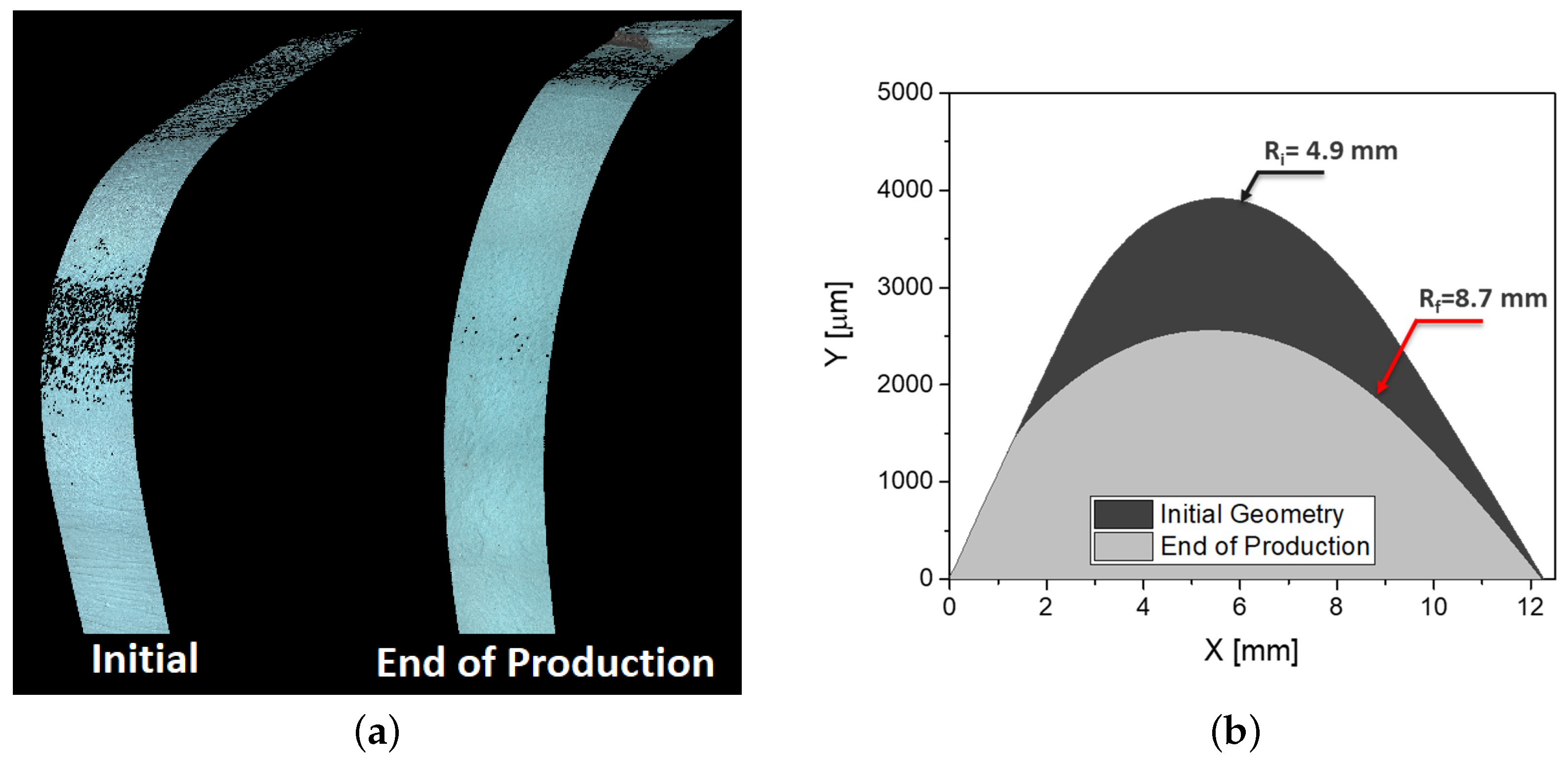
4.3.4. Ploughing
5. Discussion
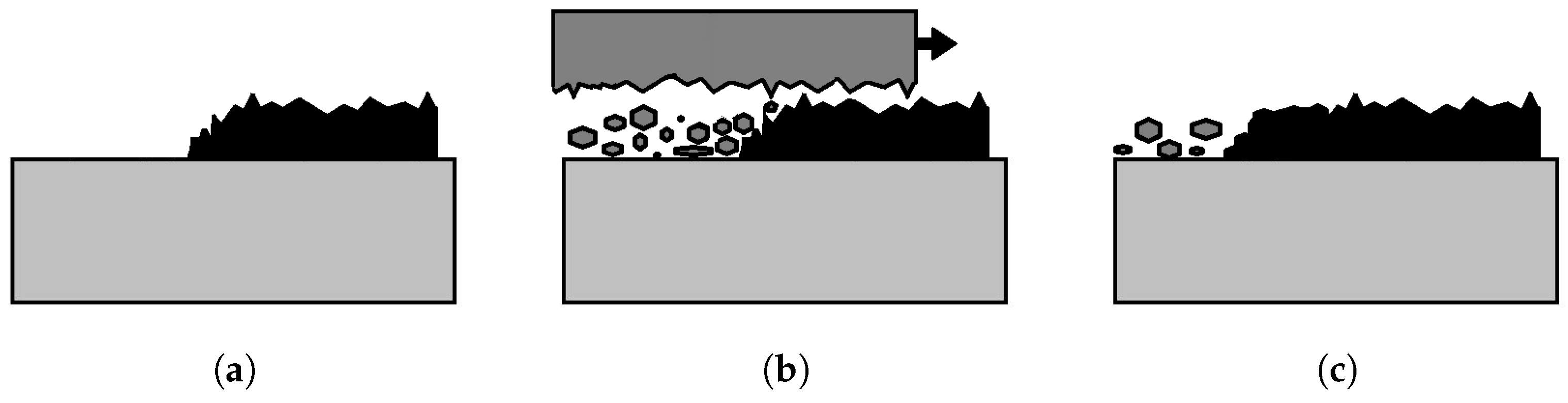
5.1. Material Transfer as the Compaction of Loose Wear Debris
5.2. Compact vs. Sparse Material Transfer
5.3. Initiation of Material Transfer
6. Conclusions
- The main wear mechanism appearing in the press hardening of AlSi-coated boron steel is material transfer. This material transfer is not only related to chemical interaction, but is also generated via mechanical means. The contribution of the latter is decisive in the growth of macroscopic wear features.
- The coating in AlSi-coated boron steel is hard and brittle, showing hardness levels (up to 14 GPa) that are well above a bare tool steel. Moreover, the heat treatment time does not affect the properties of each individual layer, but only their relative proportions.
- Particles can flake off the coating under different conditions, notably during sliding with an external surface (namely, the tool), or in locations of severe plastic deformation. The natural consequence of this is that drawing radii and slope changes are locations where dust generation will be particularly active.
- The compaction of wear debris from the coating is the main micromechanism resulting in the formation of macroscopic features on industrial tools. This phenomenon can readily occur on nucleation spots on the tool surface, even for those generated by other wear mechanisms. As a consequence, this material transfer is mostly based on mechanical and topological reasons. While it has been largely assumed that chemical affinity plays a role, it has not been possible to demonstrate this in the current work.
- The hard sheet metal coating and particles flaking from it are very aggressive towards the tool steel. Abrasion marks are generated extremely fast when direct sliding under pressure takes place, and local plastic deformation can also be observed. These defects will serve as anchor points for material transfer in the form of the accumulation of dust particles.
- Tool roughness needs to be kept to a minimum. This does not only involve a good initial surface finish, but also the means to protect this surface from the aggressive abrasive wear generated by the coating particles.
- Maximizing tool surface hardness should have a beneficial impact. On the one hand, it will slow down macroscopic abrasive wear and a loss of geometry. On the other hand, it will also hamper local abrasion and plastic deformation from creating anchor points for material transfer.
- While chemical adhesion has not been demonstrated in this work, a tool surface with low affinity for the coating will make it easier to dislodge adhesion during maintenance, or even through the cycles.
Author Contributions
Funding
Data Availability Statement
Conflicts of Interest
References
- Merklein, M.; Lechler, J. Investigation of the thermo-mechanical properties of hot stamping steels. J. Mater. Process. Technol. 2006, 177, 452–455. [Google Scholar] [CrossRef]
- Nagathan, A.; Penter, L. Chapter 7: Hot Stamping. In Proceedings of the Sheet Metal Forming—Processes and Applications; Altan, T., Tekkaya, A., Eds.; ASM International: Detroit, MI, USA, 2012; pp. 153–163. [Google Scholar]
- Georgiadis, G.; Tekkaya, A.; Weigert, P.; Weiher, J.; Kurz, H. Investigations on the Manufacturability of Thin Press Hardened Steel Components. Procedia CIRP 2014, 18, 74–79. [Google Scholar] [CrossRef]
- Neugebauer, R.; Altan, T.; Geiger, M.; Kleiner, M.; Sterzing, A. Sheet metal forming at elevated temperatures. CIRP Ann.-Manuf. Technol. 2006, 55, 793–816. [Google Scholar] [CrossRef]
- Karbasian, H.; Tekkaya, A. A review on hot stamping. J. Mater. Process. Technol. 2010, 210, 2103–2118. [Google Scholar] [CrossRef]
- Suehiro, M. Properties of Aluminum-coated Steels for Hot-forming. Nippon. Steel Tech. Rep. 2003, 88, 16–21. [Google Scholar]
- Fan, D. A review of the physical metallurgy related to the hot press forming of advanced high strength steel. Steel Res. Int. 2009, 80, 241–248. [Google Scholar]
- Grigorieva, R.; Drillet, P.; Mataigne, J.M.; Redjaïmia, A. Phase Transformations in the Al-Si Coating during the Austenization Step. Solid State Phenom. 2011, 174–174, 748–790. [Google Scholar]
- Allély, C.; Dosdat, L.; Clauzeau, O.; Ogle, K.; Volovitch, P. Anticorrosion mechanisms of aluminized steel for hot stamping. Surf. Coatings Technol. 2014, 238, 188–196. [Google Scholar] [CrossRef]
- Pelcastre, L.; Hardell, J.; Prakash, B. Galling mechanisms during interaction of tool steel and Al–Si coated ultra-high strength steel at elevated temperature. Tribol. Int. 2013, 67, 263–271. [Google Scholar] [CrossRef]
- Boher, C.; Roux, S.L.; Penazzi, L.; Dessain, C. Experimental investigation of the tribological behavior and wear mechanisms of tool steel grades in hot stamping of a high-strength boron steel. Wear 2012, 294–295, 286–295. [Google Scholar] [CrossRef]
- Ghiotti, A.; Sgarabotto, F.; Bruschi, S. A novel approach to wear testing in hot stamping of high strength boron steel sheets. Wear 2013, 302, 1319–1326. [Google Scholar] [CrossRef]
- Hardell, J. High Temperature Tribology of High Strength Boron Steel and Tool Steels. Ph.D. Thesis, Luleå Tekniska Universitet, Luleå, Sweden, 2009. [Google Scholar]
- Pelcastre, L. High Temperature Galling: Influencing Parameters and Mechanisms. Ph.D. Thesis, Luleå University of Technology, Luleå, Sweden, 2013. [Google Scholar]
- Venema, J.; Atzema, E.; Hazrati, J.; Matthews, D.; van den Boogaard, T. Modelling of Friction in Hot Stamping. Procedia Manuf. 2020, 47, 596–601. [Google Scholar] [CrossRef]
- Pelcastre, L.; Kurnia, E.; Hardell, J.; Decrozant-Triquenaux, J.; Prakash, B. High temperature tribological studies on hardfaced tool steels for press hardening of Al-Si coated boron steel. Wear 2021, 476, 203728. [Google Scholar] [CrossRef]
- Venema, J.; Stache, R.; Kotzian, M. Hot Strip Draw Wear Test and Influence of Tool Material on Adhesive and Abrasive Wear. In Proceedings of the 8th International Conference on Hot Sheet Metal Forming of High-Performance Steel CHS2 2022, Barcelona, Spain, 30 May–2 June 2022; Oldenburg, M., Hardell, J., Casellas, D., Eds.; Verlag Wissenschaftliche Scripten: Auerbach, Germany, 2022; pp. 171–178, ISBN 978-3-95735-150-0. [Google Scholar]
- Pujante, J.; Garcia-Llamas, E.; Casellas, D. Study of Wear in Press Hardening Using a Pilot Facility. In Proceedings of the 7th International Conference on Hot Sheet Metal Forming of High-Performance Steel CHS2 2019, Luleå, Sweden, 2–5 June 2019; Oldenburg, M., Hardell, J., Casellas, D., Eds.; Verlag Wissenschaftliche Scripten: Auerbach, Germany, 2019; pp. 151–158, ISBN 978-3-95735-104-3. [Google Scholar]
- Pujante, J.; Vilaseca, M.; Eriksson, K.; Clobes, J.; Alsmann, M.; Casellas, D. Wear mechanism identification on hot stamping tools. In Proceedings of the 3rd International Conference on Hot Sheet Metal Forming of High-Performance Steel CHS2 2011, Kassel, Germany, 13–16 June 2011; Oldenburg, M., Prakash, B., Steinhoff, K., Eds.; Verlag Wissenschaftliche Scripten: Auerbach, Germany, 2011; pp. 377–384, ISBN 978-3-942267-17-5. [Google Scholar]
- Pelcastre, L.; Hardell, J.; Herrera, N.; Prakash, B. Investigations into the damage mechanisms of form fixture hardening tools. Eng. Fail. Anal. 2012, 25, 219–226. [Google Scholar] [CrossRef]
- Vilaseca, M.; Pujante, J.; Ramírez, G.; Casellas, D. Investigation into adhesive wear of PVD coated and uncoated hot stamping production tools. Wear 2013, 308, 148–154. [Google Scholar] [CrossRef]
- Oliver, W.; Pharr, G. An improved technique for determining hardness and elastic modulus using load and displacement sensing indentation experiments. J. Mater. Res. 1992, 7, 1564–1583. [Google Scholar] [CrossRef]
- Kondratiuk, J.; Kuhn, P. Tribological investigation on friction and wear behaviour of coatings for hot sheet metal forming. Wear 2011, 270, 839–849. [Google Scholar] [CrossRef]
- Azkona, I.; Pujante, J.; Garcia-Llamas, E.; Caro, J.; Orrit-Prat, J.; Bonet, R. A Novel PVD Coating for Wear Reduction in Press Hardening Tools. In Proceedings of the 8th International Conference on Hot Sheet Metal Forming of High-Performance Steel CHS2 2022, Barcelona, Spain, 30 May–2 June 2022; Oldenburg, M., Hardell, J., Casellas, D., Eds.; Verlag Wissenschaftliche Scripten: Auerbach, Germany, 2022; pp. 513–520, ISBN 978-3-95735-150-0. [Google Scholar]
- Nilsson, L.; Ohlsson, R. Accuracy of replica materials when measuring engineering surfaces. Int. J. Mach. Tools Manuf. 2001, 41, 2139–2145. [Google Scholar] [CrossRef]
- Jonsson, P. Sheet Metal Trimming Dies-Characterisation Methods of Geometry and Surface Topography and Influence on Wear. Diploma Thesis, Chalmers University of Technology, Gothenburg, Sweden, 2010. [Google Scholar]
- Fan, D.; de Cooman, B. State-of-the-Knowledge on Coating Systems for Hot Stamped Parts. Steel Res. Int. 2012, 83, 412–433. [Google Scholar] [CrossRef]
- Kiani-Rashid, A.; Edmonds, D. Phase transformation study of aluminium-containing ductile cast irons by dilatometry. Mater. Sci. Eng. A 2008, 481–482, 752–756. [Google Scholar] [CrossRef]
- Gui, Z.X.; Wang, K.; Zhang, Y.S.; Zhu, B. Cracking and interfacial debonding of the Al–Si coating in hot stamping of pre-coated boron steel. Appl. Surf. Sci. 2014, 316, 595–603. [Google Scholar] [CrossRef]
- Archard, J. Contact and Rubbing of Flat Surfaces. J. Appl. Phys. 1953, 24, 981–988. [Google Scholar] [CrossRef]
- Heinrichs, J.; Jacobson, S. The influence from shape and size of tool surface defects on the occurrence of galling in cold forming of aluminium. Wear 2011, 271, 2517–2524. [Google Scholar] [CrossRef]
- Menezes, P.; Kishore, S.; Kalias, V. Studies on friction and transfer layer: Role of surface texture. Tribol. Lett. 2006, 24, 265–273. [Google Scholar] [CrossRef]
- Pelcastre, L.; Hardell, J.; Courbon, C.; Prakash, B. Tribological behaviour of Al-Si-coated ultra-high-strength steel during interaction with tool steel at elevated temperatures: Influence of tool steel surface topography parameters on galling. Proc. Inst. Mech. Eng. Part B J. Eng. Manuf. 2015, 229, 1373–1384. [Google Scholar] [CrossRef]
- Pelcastre, L.; Hardell, J.; Prakash, B. Investigations into the occurrence of galling during hot forming of Al–Si-coated high-strength steel. Proc. Inst. Mech. Eng. Part J J. Eng. Tribol. 2011, 225, 487–498. [Google Scholar] [CrossRef]
- Venema, J.; Hazrati, J.; Matthews, D.; Stegeman, R.; van den Boogaard, A. The effects of temperature on friction and wear mechanisms during direct press hardening of Al-Si coated ultra-high strength steel. Wear 2018, 406–407, 149–155. [Google Scholar] [CrossRef]
- Pujante, J.; Vilaseca, M.; Casellas, D.; Riera, M.D. The Role of Adhesive Forces and Mechanical Interaction on Material Transfer in Hot Forming of Aluminium. Tribol. Lett. 2015, 59, 10. [Google Scholar] [CrossRef]
- Ghiotti, A.; Bruschi, S.; Medea, F.; Hamasaiid, A. Tribological behavior of high thermal conductivity steels for hot stamping tools. Tribol. Int. 2016, 97, 412–422. [Google Scholar] [CrossRef]
- Schedin, E. Galling mechanisms in sheet forming operations. Wear 1994, 179, 123–128. [Google Scholar] [CrossRef]
- Deng, L.; Pelcastre, L.; Hardell, J.; Prakash, B.; Oldenburg, M. Numerical investigation of galling in a press hardening experiment with AlSi-coated workpieces. Eng. Fail. Anal. 2019, 99, 85–96. [Google Scholar] [CrossRef]
- Medea, F.; Venturato, G.; Ghiotti, A.; Bruschi, S. Tribological performances of new steel grades for hot stamping tools. J. Phys. Conf. Ser. 2017, 896, 012047. [Google Scholar] [CrossRef]
- Pujante, J.; González, B.; Garcia-Llamas, E. Pilot Demonstration of Hot Sheet Metal Forming Using 3D Printed Dies. Materials 2021, 14, 5695. [Google Scholar] [CrossRef] [PubMed]


| Component Produced | Tool Material | Hardness | Sheet Metal Material |
|---|---|---|---|
| B-Pillar | DIN 1.2367 | 48 HRC | AlSi-coated Boron Steel |
| B-Pillar | DIN 1.2344 | 48–50 HRC | AlSi-coated Boron Steel |
| Frame Dash Panel | DIN 1.2367 | 48 HRC | AlSi-coated Boron Steel |
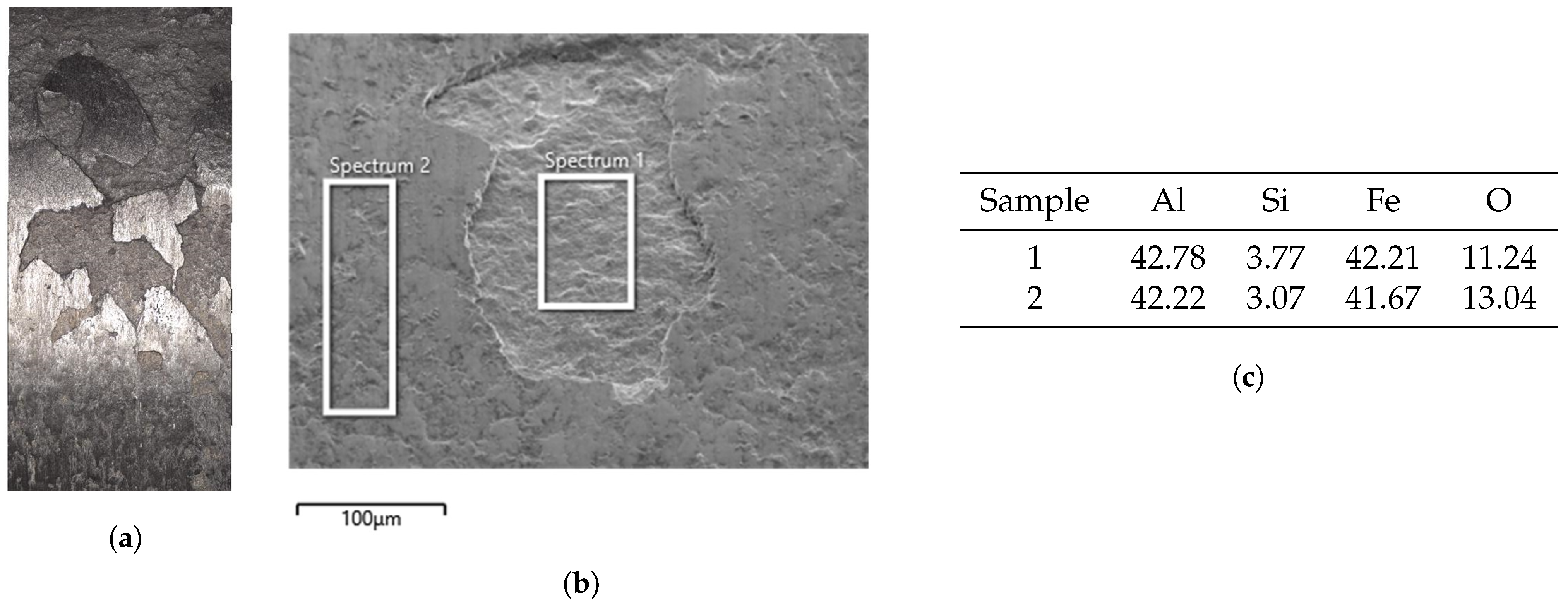
| Sample | Al | Si | Mn | Fe |
|---|---|---|---|---|
| 1 | 37.3 | 11.9 | 0.6 | 41.8 |
| 2 | 45.6 | 6.1 | 0.6 | 44.1 |
| 3 | 36 | 7 | 0.7 | 49.1 |
Disclaimer/Publisher’s Note: The statements, opinions and data contained in all publications are solely those of the individual author(s) and contributor(s) and not of MDPI and/or the editor(s). MDPI and/or the editor(s) disclaim responsibility for any injury to people or property resulting from any ideas, methods, instructions or products referred to in the content. |
© 2023 by the authors. Licensee MDPI, Basel, Switzerland. This article is an open access article distributed under the terms and conditions of the Creative Commons Attribution (CC BY) license (https://creativecommons.org/licenses/by/4.0/).
Share and Cite
Pujante, J.; Garcia-Llamas, E.; Ramírez, G.; Cuadrado, N.; Ademaj, A.; Vilaseca, M.; Casellas, D. Wear Mechanisms in Press Hardening: An Analysis through Comparison of Tribological Tests and Industrial Tools. Lubricants 2023, 11, 222. https://doi.org/10.3390/lubricants11050222
Pujante J, Garcia-Llamas E, Ramírez G, Cuadrado N, Ademaj A, Vilaseca M, Casellas D. Wear Mechanisms in Press Hardening: An Analysis through Comparison of Tribological Tests and Industrial Tools. Lubricants. 2023; 11(5):222. https://doi.org/10.3390/lubricants11050222
Chicago/Turabian StylePujante, Jaume, Eduard Garcia-Llamas, Giselle Ramírez, Nuria Cuadrado, Agim Ademaj, Montserrat Vilaseca, and Daniel Casellas. 2023. "Wear Mechanisms in Press Hardening: An Analysis through Comparison of Tribological Tests and Industrial Tools" Lubricants 11, no. 5: 222. https://doi.org/10.3390/lubricants11050222
APA StylePujante, J., Garcia-Llamas, E., Ramírez, G., Cuadrado, N., Ademaj, A., Vilaseca, M., & Casellas, D. (2023). Wear Mechanisms in Press Hardening: An Analysis through Comparison of Tribological Tests and Industrial Tools. Lubricants, 11(5), 222. https://doi.org/10.3390/lubricants11050222