Article

Dry and Minimum Quantity Lubrication Machining of Additively Manufactured IN718 Produced via Laser Metal Deposition

1
Faculty of Engineering Technology, Department of Materials Engineering, KU Leuven, Campus De Nayer, 2860 Sint-Katelijne Waver, Belgium
2
Joining and Welding Research Institute, Osaka University, Osaka 567-0047, Japan
3
Department of Mechanical Program, Hacettepe University, Ankara 06930, Turkey
*
Author to whom correspondence should be addressed.
Lubricants 2023, 11(12), 523; https://doi.org/10.3390/lubricants11120523
Submission received: 4 November 2023 / Revised: 30 November 2023 / Accepted: 6 December 2023 / Published: 10 December 2023
(This article belongs to the Special Issue Laser Surface Engineering for Tribology)

Abstract

:
Inconel 718 (IN718), a Ni-based superalloy, is immensely popular in the aerospace, nuclear, and chemical industries. In these industrial fields, IN718 parts fabricated using conventional and additive manufacturing routes require subsequent machining to meet the dimensional accuracy and surface quality requirements of practical applications. The machining of IN718 has been a prominent research topic for conventionally cast, wrought, and forged parts. However, very little attention has been given to the machinability of IN718 additively manufactured using laser metal deposition (LMD). This lack of research can lead to numerous issues derived from the assumption that the machining behavior corresponds to conventionally fabricated parts. To address this, our study comprehensively assesses the machinability of LMDed IN718 in dry and minimum quantity lubrication (MQL) cutting environments. Our main goal is to understand how LMD process variables and the cutting environment affect cutting forces, tool wear, surface quality, and energy consumption when working with LMDed IN718 walls. To achieve this, we deposited IN718 on SS309L substrates while varying the following LMD process parameters: laser power, powder feed rate, and scanning speed. The results unveil that machining the deposited wall closer to the substrate is significantly more difficult than away from the substrate, owing to the variance in hardness along the build direction. MQL greatly improves machining across all processing parameters regardless of the machining location along the build direction. Laser power is identified as the most influential parameter, along with the recommendation for a specific combination of power feed rate and scanning speed, providing practical guidelines for optimizing the machining process. While MQL positively impacts machinability, hourly energy consumption remains comparable to dry cutting. This work offers practical guidance for improving the machinability of LMDed IN718 walls and the successful adoption of LMD and the additive–subtractive machining chain. The outcomes of this work provide a significant and critical understanding of location-dependent machinability that can help develop targeted approaches to overcome machining difficulties associated with specific areas of the LMDed structure. The finding that MQL significantly improves machining across all processing parameters, particularly in the challenging bottom region, offers practical guidance for selecting optimal cutting conditions. The potential economic benefits of MQL in terms of tool longevity without a substantial increase in energy costs is also highlighted, which has implications for incorporating MQL in several advanced manufacturing processes.

1. Introduction

The utilization of laser metal deposition (LMD), a variant of the directed energy deposition (DED)-based additive manufacturing (AM), holds widespread potential for the manufacture, remanufacture, and repair of critical high-value-added components [1], and the fabrication of wear- and corrosion-resistant coatings [2]. Owing to the flexibilities and benefits like high power density, production and geometric freedom, stability, controllability, low thermal input (i.e., small heat-affected zone), strong metallurgical bonding, less post-deposition deformation, ability to process difficult-to-machine materials (e.g., Ti alloys, Ni-based superalloys), and low buy-to-fly ratio (~1.5:1) [3], LMD has anchored its position as a competitive and highly versatile AM technology [4]. The LMD process, due to its highly localized deposition nature, allows for the addition of the right material at the right place for components with different degrees of geometrical complexity [5]. The process can produce parts with almost 100% density and reliable metallurgical properties that meet the requirement for direct usage, thus enabling the preceding use of costly forming dies and tooling [6]. Despite the multiple technological advantages, the surface quality and dimensional accuracy of the parts fabricated via LMD do not meet the geometrical and mechanical requirements of practical applications [7], thereby necessitating a subsequent post-processing or finishing step. AM using LMD typically produces surfaces with an average roughness of ≥10 μm [7], whereas most mechanical systems in critical applications require much smoother surfaces [8]. Although laser-based surface finishing approaches like laser re-melting [7] and laser polishing [9] exist, the achievable improvement in surface roughness more often than not satisfies the stringent requirements of international standards. Thus, part fabrication using LMD almost always requires a successive end-machining process.
LMD-based AM is being rapidly adapted for fabricating and repairing high-performance alloys [10]. Among several of these alloys, Ni-based superalloy Inconel 718 (IN718), ubiquitous in industrial gas turbines, jet engine components (turbine blades, disks, shafts, stators, and casing), nuclear power plant components, supporting structures, and pressure vessels in aerospace and oil and gas sectors [11], has received extensive attention. While the AM of IN718 parts with the LMD technique is ever-increasing, challenges pertaining to its machinability remain unresolved, leading to the significant usage of resources and costs in terms of tool wear, material waste, and lead time [12]. Thus, even though the LMD process is often deemed vastly productive, the productivity of LMD for IN718 remains a critical factor that merits further investigation.
IN718, despite its exceptional properties, is among the most difficult-to-machine materials [13]. Due to the high concentration of alloying elements, IN718 resists plastic deformation during machining, leading to rapid strain hardening [8]. Under such situations, the machining of IN718 often leads to the formation of undesirable residual stresses and dimensional inaccuracy. In addition, the poor thermal conductivity of IN718 results in a rapid temperature rise of the machined surface, leading to degraded surface quality and occasional burns [14]. Machinability of IN718 fabricated by conventional and DED AM routes has been evaluated and compared in limited studies in recent years. Bagherzadeh et al. [15] reported that IN718 deposited via selective laser melting and DED parts is easy to machine compared to the wrought alloy, especially for machining with lubrication. However, in the case of dry machining, a larger cutting force was reported for laser-clad IN718 compared to the wrought parts, owing to differences in grain geometries [16]. The machinability of DED IN718 parts improves with high-temperature machining (400 °C) of the fabricated parts, leading to higher surface quality and significantly lower tool wear than room-temperature machining [17]. The machining aspects of IN718/SS316L functionally graded material (FGM) fabricated by laser DED AM were recently evaluated by Li et al. [18] and Zhang et al. [19]. In both studies, the machining of the sections in the FGM containing more IN718 than SS316L led to higher cutting forces and the generation of more cutting heat, owing to the higher hardness and strength of the IN718. New techniques like cryogenic cooling with liquid nitrogen have been effective in significantly reducing the cutting forces and tool wear during the machining of LMDed IN718 [20].
Although significant technical knowledge is available to tackle the challenges associated with machining conventionally cast, wrought, and forged IN718 parts, there is a dearth of scientific research and practical know-how of the intricacies of machining LMDed IN718. The absence or lack thereof of such studies can lead to multifold problems derived from the basic assumption that the machining behavior corresponds to that of conventionally fabricated parts. Development of a fundamental understanding of how AM affects the machining operation is rather critical, as the properties (mechanical, chemical, etc.) of AM parts [21], and in particular, those fabricated by LMD [22], are strikingly different from conventionally manufactured parts. Considering the increased push for LMD integration in industries, it is crucial to highlight that machining an LMDed difficult-to-machine material like IN718 implies additional challenges, reflected in the final surface quality and dimensional accuracy, and thus, it is vital to understand the LMD process effect on the machinability aspects of IN718. Pereira et al. [23] evaluated the cutting forces and surface roughness for LMDed IN718 preforms. The research highlighted considerably improved surface finish with down milling and significantly higher cutting forces while machining in the zone near the substrate (i.e., build platform). The reason for differences along the build direction was attributed to the LMD process-generated rigidity and residual stress; however, it was not scientifically explored. A proper understanding of this behavior is significant as it can guide tooling and machining parameter selection. The effect of post-deposition heat treatment on the machining of LMD parts has been another area of recent focus. Studies conducted by both Careri et al. [24] and Calleja et al. [25] revealed that the machining heat-treated LMDed IN718 parts led to higher surface roughness values and significant tool wear, implying the employment of heat treatments downstream of the machining operations. The study of the chip morphology for the machining of LMDed IN718 has also been a subject of interest. Unlike the continuous chip formation in the forged [8] and cast [26] parts, machining the LMDed IN718 surface leads to irregular lamellar chip formation. These differences arise from the anisotropy in material properties in AM, particularly with the growth of coarse grains along the build-up direction. The irregular chip formation was reflected in the steep fluctuations in measured cutting forces. Zhou et al. [27] optimized the laser parameters for LDED of alloy GH4169 (an alloy equivalent of IN718 developed in China); however, the objective of the work was to evaluate the effect of interrupted machining passes in between deposition passes on the phase formation, element segregation, and performance of the GH4169 alloy.
Central to the seamless implementation of the LMD AM in industries is the minimization of the post-deposition machining requirements. The present investigation is motivated by the critical review of the literature, wherein it is evident that although preliminary work focusing on the machining of LMDed IN718 is available, the previous studies do not elucidate the fundamentals governing the interplay between the process and the ensuing machinability of the fabricated part for variation in LMD processing parameters. Moreover, existing studies on the machining of LMDed IN718 do not address the influence of the cutting environment on the machinability aspects. In this work, the term “cutting environment” pertains to the cooling and lubrication applied in the cutting zone, encompassing both dry machining, where no cutting fluids are used, and minimum quantity lubrication machining (MQL), where the controlled application of cutting fluid is applied. In the MQL approach, a very small amount of cutting fluid is mixed with a carrier gas such as air, CO2, N2, etc. The cutting fluid makes a layer on the cutting surface and favorably impacts the cooling and lubrication phenomenon, as explained later in Section 2. The MQL is proven to be useful in the machining of difficult-to-cut materials [14].
The purpose of this study is to address the critical research gaps with practical implications by incorporating a comprehensive assessment of the machinability of IN718 over a wide-ranging set of LMD processing parameters and considering two different types of machining environments, i.e., dry and minimum quantity lubrication (MQL). Recent work by Gupta et al. [28] has proven the efficacy of machining (turning) 2205 duplex steel under MQL. The implementation of the MQL, a sustainable machining approach, led to significant improvement in surface quality and lowering of the tool wear and energy consumption. Our main goal is to understand how LMD process variables and the cutting environment affect cutting forces, surface quality, surface temperatures, tool wear, and energy consumption when working with LMDed IN718 walls. For the mentioned goal, IN718 is deposited on cold-rolled SS309L substrates with varying LMD process parameters, including laser power, powder feed rate, and scanning speed, and the effect of variation in these parameters on the machinability is examined. The machinability and its variation (if any) along the build direction are correlated with hardness distribution, the most significant LMD process parameters(s) are identified, the effect of process parameters on machining under both dry and MQL environments is critically analyzed, followed by the identification of suitable process parameter-cutting environment combination for the ease of machining. The rest of this paper is organized as follows: Section 2 presents the details about the materials and experimental procedure; Section 3 provides a detailed discussion of the obtained results; and finally, Section 4 draws conclusions from this study and provides future research directions.

2. Materials and Methods

The experimental workflow in this study is divided into two stages, i.e., material deposition and post-deposition machining. A flowchart of the experimental plan is provided in Figure 1, with elaborate details provided in Section 2.1 and Section 2.2.

2.1. Material Deposition

IN718 powder with an average diameter of 30 μm is deposited on SS309L substrates with a disk laser with a wavelength of 1030 nm and a beam diameter of 2 mm. The choice of stainless steel (SS) as the substrate material arises from the fact that the fabrication of sound metallurgical IN718-SS AM joints has been repeatedly demonstrated in the literature [29]. In addition, the use of steel as the substrate instead of IN718 acts as a cost reduction means in the AM chain and is thus of industrial interest. During the deposition, combinations of laser power, scanning speed, and powder feed rate are used at five levels, as presented in Table 1. Multi-pass, multi-layer deposition is carried out to reach the desired part thickness per the deposition scheme in Figure 2a. A total of 6 passes with a hatch distance of 1 mm are employed for each layer. The total number of layers varied depending on the individual layer height, directly related to the operating process parameters. The substrate’s initial temperature was equivalent to the standard room temperature during the deposition. The final dimensions of the wall geometry of IN178 and the substrate dimensions are depicted in Figure 2b. For post-deposition, samples approximately 10 mm wide from the left and right edges of the main material are cut for hardness mapping, as depicted in Figure 2c. Standard metallographic procedures are employed for grinding, polishing, and etching the samples. A low-force Vickers hardness test (HV0.2) based on EN ISO 6507-1 standard with a 0.2 kgf load and dwell time of 15 s is performed on the deposited parts using a ZwickRoell-make DuraScan Microhardness tester. Detailed information on the hardness test is provided in Section 3.

2.2. Post-Deposition Machining

The experimental setup utilized for the machinability evaluation is presented in Figure 3. A 3-axis Frontier MCV-866 CNC vertical milling machine with a maximum spindle speed of 10,000 rpm is used. While machining, the cutting forces are recorded with a Kistler 9272 dynamometer at a sampling frequency of 20 kHz. The collected force data provide the radial/axial forces and the resultant forces. To accurately identify chatter and peak states in cutting forces, the machining tests are performed using a single insert at an entering angle of 90°. PVD-coated AOMT123608PEER-M VP15TF cutting inserts with a nose radius of 0.8 mm are used for the machinability evaluation experiments. The insert is mounted on a standard BBT 40 tool holder with a diameter of 16 mm, and each machining test is carried out using a fresh edge. The optimized milling parameters provided in Table 2 are utilized for the machining study under dry and MQL cutting environments. The MQL technique presents an environmentally friendly alternative for machining operations, involving the supply of a minimal amount of oil to the cutting zone in the form of an emulsion with a carrier gas, typically air. This oil + air emulsion spreads across the tool–chip interface, enhancing heat transfer by influencing the heat transfer coefficient. Additionally, it significantly reduces friction at the interface in a discernible manner, allowing for the friction coefficient to be expressed in terms of the machining parameters [30]. Consequently, MQL has proven to be particularly advantageous in the machining of difficult-to-machine materials such as titanium and nickel alloys.
The post-deposition machining parameters are determined based on two factors. Firstly, several pilot experiments are conducted to reach suitable values, and secondly, catalog data provided by the cutting tool manufacturer are utilized to narrow down the parameter selection process. During machining, the collected force data provide the active forces (radial Fy/axial Fx) and the passive forces (Fz). Since the depth of the cut value is constant, the effect of the passive force is negligible [31,32]; therefore, the resultant force was calculated with radial and axial forces. This study compares the maximum resulting forces during cutting in all cutting conditions, as shown in the representative force-time plot in Figure 4a. During the machining process, the temperature of the machined surfaces is measured using an MI3 pyrometer and a Testo 872 thermal camera. Before the actual experiments, the pyrometer and the thermal camera were calibrated. The deposited IN718 wall is heated using an open-torch flame, and the temperatures during cooling are recorded using thermocouples connected to a data acquisition unit. Simultaneously, the temperature measurements are also conducted using the pyrometer and the thermal camera, and their emissivity factors are adjusted until the temperatures measured by the pyrometer and the thermal camera match the temperature read from the thermocouple. The temperature of the cutting zones is measured while the positions of the pyrometer and the thermal camera are fixed. The temperature data analysis was performed using the IR Soft software. After each cutting operation, as seen in Figure 4b, the maximum temperature of the cutting zone during machining was detected using IR Soft. For the MQL, a biodegradable cutting oil called Viscol Viscut is employed. This cutting oil has a kinematic viscosity of 37–40 cSt at 40 °C and a density of 0.88 g/cm3 at 15 °C, with a flash point exceeding 240 °C. The oil is used with a Werte STN40 lubrication system to facilitate lubrication and air cooling at the machining interface. It is directly applied to the cutting area to ensure effective lubrication. The MQL nozzle is precisely positioned 15 mm from the cutting point, maintaining a 20° angle relative to the machine’s X–Y plane.
The flow rate of the oil is set at 10 mL/min. The milling parameters are kept constant to observe the effect of the cutting environment on the machined cutting forces, tool wear, surface quality, and energy consumption in the machining of LMD-fabricated IN718 workpieces. The energy consumption of the machine is recorded using a Fluke 435 power quality and energy analyzer. The milling of IN718 walls is conducted in two regions, i.e., the top and bottom, as represented in Figure 2c. The top region is machined first, followed by machining of the bottom region using the same tool. There is an interruption between the machining of the top and bottom regions. The distinction between the top and bottom regions is critical, as the bottom region is related to the initial deposition layers, whereas the top region, where the final layers are deposited, may be subject to very different thermo-mechanical process conditions, geometric distortions, and resulting mechanical properties. The front and back surfaces of the IN718 wall are machined under dry and MQL environments, respectively. Post machining, the roughness of the machined surface is evaluated using a contact-based Mitutoyo surftest SJ-210 tester. Surface roughness measurements of machined surfaces are conducted in alignment with both the machining and deposition directions at three locations on each part. Optical microscopy was used to analyze the cutting insert wear.

3. Results and Discussion

3.1. Surface Appearance

The LMDed IN718 wall has an irregular surface resulting from the presence of unmelted powder particles that stick to the side surfaces of the walls, as seen in Figure 5. The degree of unmelted powder particles sticking to the surface is directly related to the size of the molten pool, which in turn is influenced by the laser power. Due to the shape of the heat source, i.e., the laser beam, the energy density in the middle of the molten pool is greater than that near the edge. The high-energy-density region corresponds to higher temperatures, whereas toward the edge, there is a gradual decrease in temperature due to depleting energy density. As a consequence, there is a higher probability that the incoming powder particles remain unmelted at the edges and get stuck to the deposited surface. With a smaller melt pool, the number of powder particles that remain unmelted is expected to be greater. The laser power dictates the melt pool size, i.e., larger melt pools at higher laser power. The interplay of laser power and the ensuing melt pool size decides the quality and appearance of the as-deposited LMDed wall surfaces, verified by the results presented in Figure 5a–c.
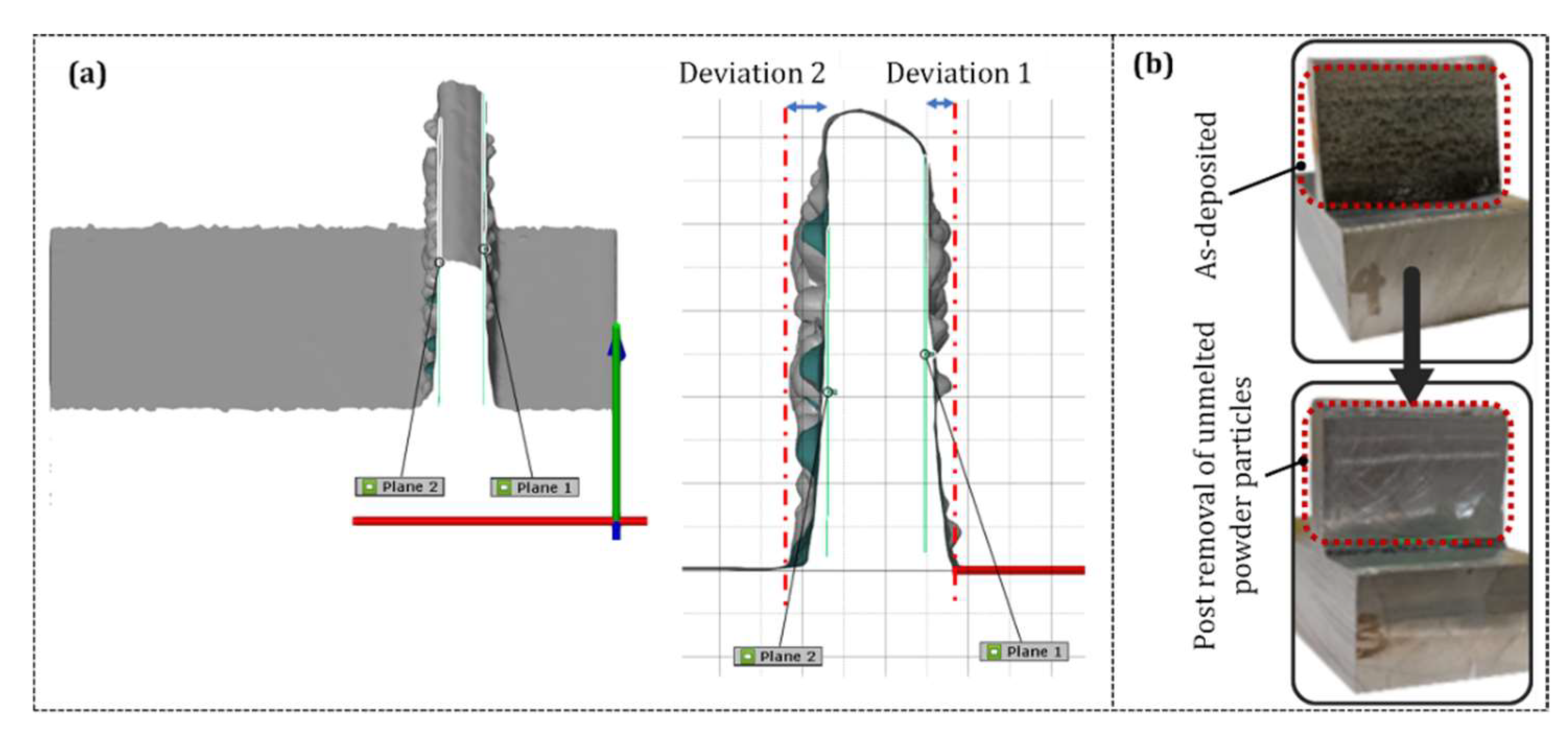
As a consequence of the unmelted powder particles sticking to the surface of the deposited part, the targeted part thickness of 6 mm of the IN718 wall is not achieved. Evaluating the machinability with highly irregular surfaces, as in this case, is a precursor to erroneous results. In particular, variable forces are obtained since the depth of the cut value cannot be fixed due to the high surface roughness. For this reason, prior to the machinability evaluation, the LMDed wall surfaces are pre-machined to remove the unmelted powder particles and generate a flat surface, as per the procedure described in Appendix A.

3.2. Build Direction Hardness Variation

It is well established in the literature that in LMD, the laser energy density primarily affects the thermal history and determines deposition features like microstructural morphology and size. During the deposition of the initial layers in LMD, the G/R ratio (where G is the temperature gradient and R is the solidification growth rate) is fairly large, whereas along the build direction, the ratio has a gradual decrease [1]. This variation is reflected in the anisotropy of the mechanical properties, in particular, the hardness distribution. A heterogeneous hardness distribution along the build direction leads to non-uniformity in the mechanical properties, which can specifically have a significant effect on the machinability of the deposited part.
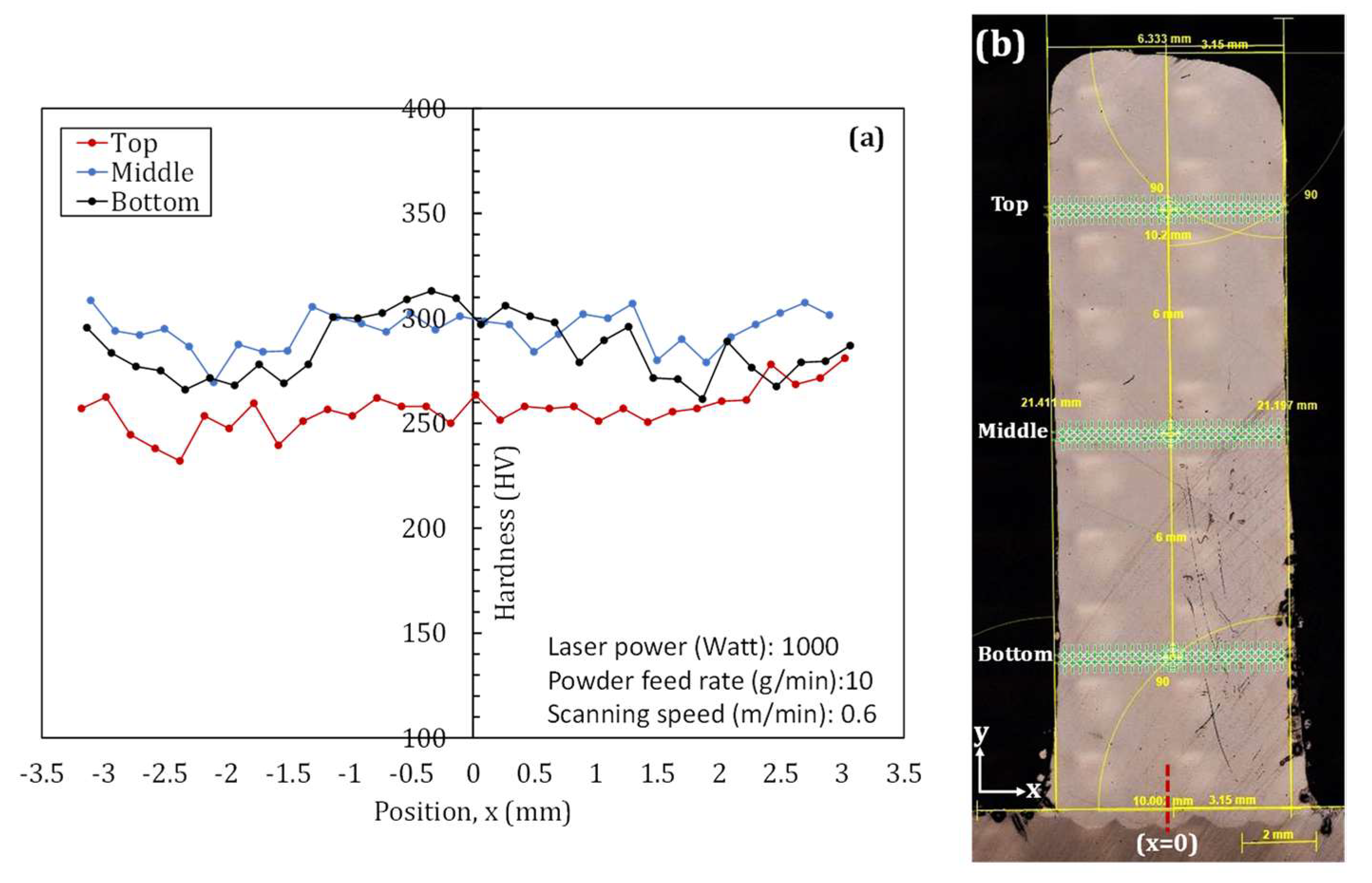
To examine the variation in hardness (if any) in the LMDed IN718 walls, hardness mapping was conducted both perpendicular (Figure 6) and parallel (Figure 7) to the build direction of the parts up to the top of the part. The hardness measurements conducted parallel to the build direction also evaluated the effect of the laser power. Figure 6 depicts the through-thickness hardness values (i.e., perpendicular to the build direction) of the LMDed IN718 wall deposited at a laser power of 1000 Watt, powder feed rate of 10 g/min, and scanning speed of 0.6 m/min, as a representative case. For each region, indentation is conducted in two lines, each containing around 50 to 54 indents, depending on the sample thickness at the location. The measurements conducted in three different regions of the sample, i.e., top, middle, and bottom, provide sufficient evidence that the hardness in the top region, i.e., IN718 deposited at a considerable distance from the substrate, had the lowest values. In contrast, the bottom and middle regions had much higher hardness. This observation was consistent for all the investigated samples. The average hardness values recorded in the top, middle, and bottom regions are 256.32 ± 10.06 HV, 294.38 ± 9.11 HV, and 285.78 ± 14.53 HV, respectively. The results presented in Figure 6 suggest that although there is considerable variation in hardness along the build direction, the through-thickness hardness remains within a narrow band (variation ≤ 5%), irrespective of the location along the build direction.
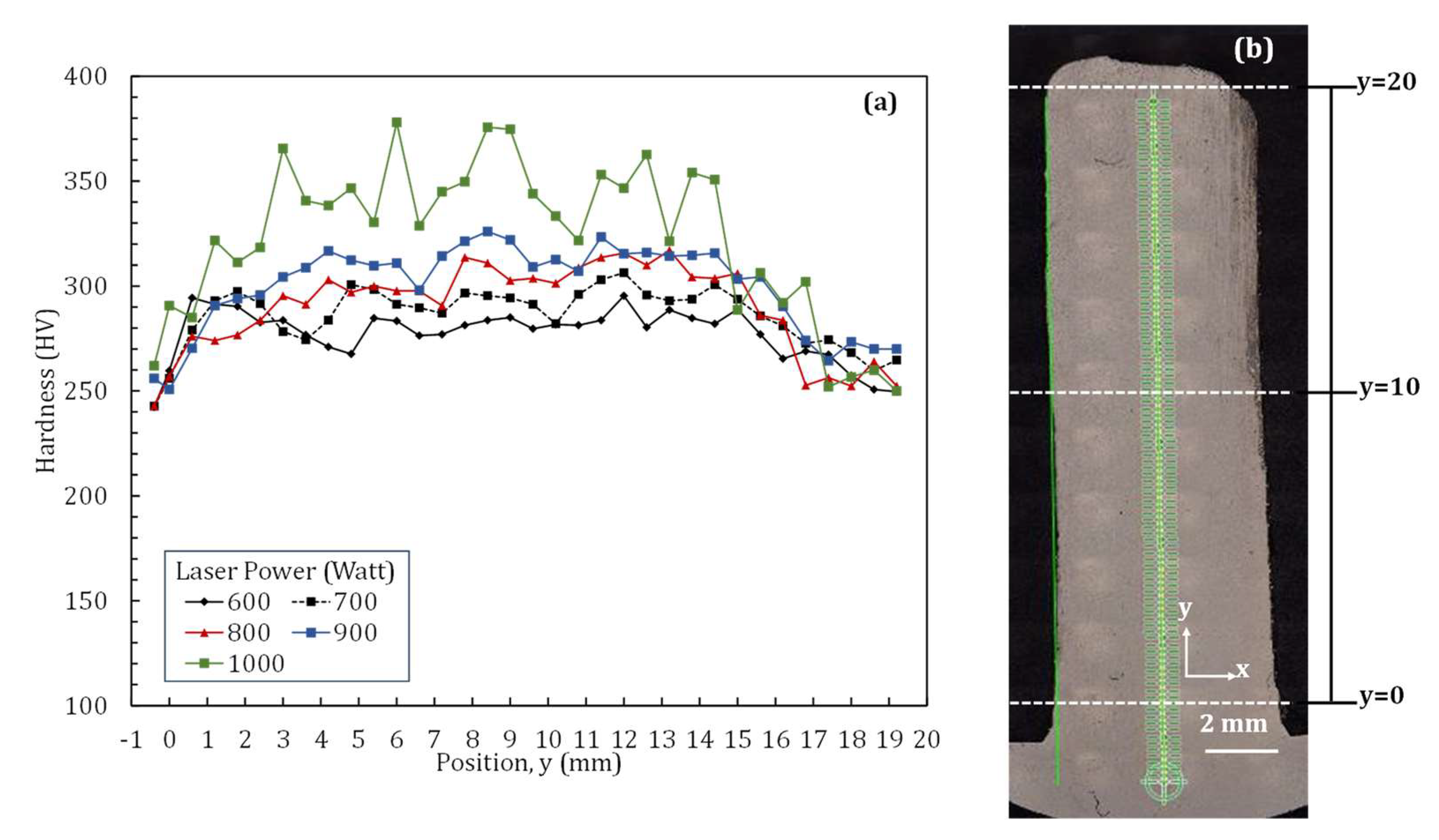
The hardness mapping presented in Figure 6 highlights the hardness heterogeneity along the build direction. The higher hardness of the deposited IN718 wall near the bottom and middle regions compared to the top region is similar to previously obtained results in the works of Tian et al. [33], Stevens et al. [34], and Li et al. [35]. Similar to previous investigations [33,34,35], an increment in the hardness in the build direction is observed in the first few layers, followed by a plateau and subsequently a decrease in the hardness in the upper layers, i.e., away from the substrate, the hardness drops (Figure 7). This hardness pattern is however distinct and is contrary to the observed hardness patterns in steels [36]. For steels, like this study, the initial layers exhibit higher hardness due to rapid cooling, followed by a decrease in hardness due to delayed cooling and annealing by the successive layers. The upper layers of AMed steels demonstrate an increase in hardness as the upper layers do not undergo annealing cycles.
The different regions along the build direction experience different thermal cycles, and these slight changes in thermal cycles influence microstructure heterogeneity. The observed hardness heterogeneity in this work can be attributed to the differences in the precipitation of the strengthening phase. Due to the high cooling rate of the LMD process, the γ″ strengthening phase in IN718 is not expected to form initially during rapid solidification but rather develop due to the subsequent heating cycles during multi-layer deposition. The lower hardness of the top region may be due to a decrease in the γ″ strengthening phase. Moreover, the build part experiences discrepancy in elemental segregation. Near the middle region, where the highest average hardness is recorded, the cooling rate is lower. This provides an opportunity for more Nb segregation, causing enhanced γ″ precipitation during multiple thermal gyrations. The closer to the top, the lower heat accumulation and less thermal cycling limit the segregation.
In LMD, the laser power dictates the thermal history, heat accumulation, and ensuing changes in microstructure and mechanical properties. For a constant scanning speed, the heat input varies with the laser power according to the relation in Equation (1):
Heat input (HI) = P/V
where P is the laser power (Watt) and V is the scanning speed (m/min). The melt pool widens for higher laser powers, resulting in a lower thermal gradient and, consequently, a slower cooling rate than the parts fabricated with a lower laser power [2]. At lower laser powers, the heat accumulation in the deposited material is very low, which allows for a faster cooling rate and the formation of smaller grain sizes. Thus, based on the literature [37] and general convention, in LMD, a higher hardness is expected for parts fabricated at lower laser powers. However, as depicted in Figure 7, the LMDed IN718 walls in this work displayed higher hardness at higher laser powers, in contrast to results in the literature. This observation is crucial as it leads to the understanding of the primary factor that controls the hardness-laser power relationship. Based on the results presented in Figure 7, it can be conclusively stated that precipitation phenomena dominate over the grain size effect in controlling the influence of laser power on hardness in LMD of IN718. For the lowest laser power of 600 W, a higher cooling rate and lower heat accumulation limit the formation of the γ″ strengthening phase. On the other hand, at a higher laser power of 1000 W, slower cooling and significant heat accumulation promote the formation of the γ″ strengthening phase. It is important to note that a further increase in laser power can lead to significantly high heat input and heat accumulation, leading to Nb dissolving into the matrix and, consequently lower hardness, as observed in the literature on a very high laser power of 1700 W [37].
A sharp increase in hardness values (~250 to 290 HV) is observed at a distance of approximately 2.5 mm from the interface (y = 0) for all the deposited walls (Figure 7). Subsequently, an overall increasing trend in hardness, albeit uneven, is observed up to around 15 mm. The variation in the hardness values between 2.5 mm and 15 mm is approximately 5.98%, 7.74%, 8.34%, 9.58%, and 14.57% for samples fabricated at laser powers of 600, 700, 800, 900, and 1000 Watts, respectively. Notably, the hardness values in the region near the substrate (0–10 mm), i.e., the bottom region, are generally higher than those in the top region (10–20 mm) of the IN718 wall, as demonstrated previously in Figure 6.

3.3. Machinability Evaluation

3.3.1. Effect of Build Direction Anisotropy and Cutting Environment

To unveil the effect of build direction property anisotropy on machinability, the cutting forces, machined surface roughness, and machining-generated surface temperatures are evaluated. The hardness results presented in Figure 7 suggest that the top region of the AM IN718 is softer, whereas both the middle and bottom regions have almost similar hardness. Following this observation, the machinability evaluation was conducted for the top and bottom regions. To further evaluate the effect of the cutting environment, machining is conducted under dry and MQL environments. Box–whisker plots presented in Figure 8a–c depict the variation in resultant cutting forces, surface roughness, and maximum temperature, respectively, over the entire range of experimental conditions. Several critical observations can be derived from Figure 8. Firstly, there is a considerable impact of machining location on the cutting forces and surface quality. The machining of the bottom region generates significantly higher cutting forces, surface roughness, and temperatures than when the top region is machined. This result correlates with the hardness results, as the bottom region exhibits much higher hardness than the top region. Secondly, while the force, roughness, and temperature values have a much larger variation for the bottom region across different samples, the variation is minimal in the top region. Thirdly, the employment of MQL considerably eases the machining of the IN718 wall, particularly in the bottom region. This is reflected in Figure 8a–c, with lower recorded cutting forces, surface roughness, and temperatures when machining is conducted under an MQL environment. The employment of MQL had the most positive influence on the surface temperature.
Dry cutting of the bottom region produced the highest cutting forces, surface roughness, and temperatures across all processing conditions. Notably, in dry cutting, the machined surface roughness in the bottom region exhibited an Ra higher than that of the machined surface in the top region due to the increased cutting forces. For dry cutting, the mean surface roughness value in the bottom region is 1.4 times that of the top region, whereas the maximum surface roughness in the bottom region is 2.4 times that of the top region. Application of the MQL cutting environment reduces the cutting forces up to 20% in the bottom region compared to the dry machining. This is because the applied lubricant forms a thin film (protective layer) between the tool and workpiece, thereby reducing friction and shear stress and facilitating smoother cutting. The cooling effect also helps dissipate heat, preventing excessive temperature rise and reducing the forces exerted on the cutting tool. In addition, the application of MQL alleviates the variability in cutting forces throughout the part (top to bottom regions) despite variations in hardness, as seen in Figure 8a. The reduced variability of cutting forces across the build direction reduces the chances of force jumps and helps prolong cutting tool life. However, the employment of MQL does not significantly alter the machinability in the top region. In particular, the cutting forces remain comparable with those of dry cutting. This observation is vital as it suggests that for LMD of IN718, machining of the part closer to the substrate, i.e., in the initial layers of deposition, has a much stronger impact on the overall machinability of the fabricated part. Based on this outcome, the results presented hereafter focus on the machining aspects of the bottom region.

3.3.2. Process Parameter–Cutting Environment Interplay

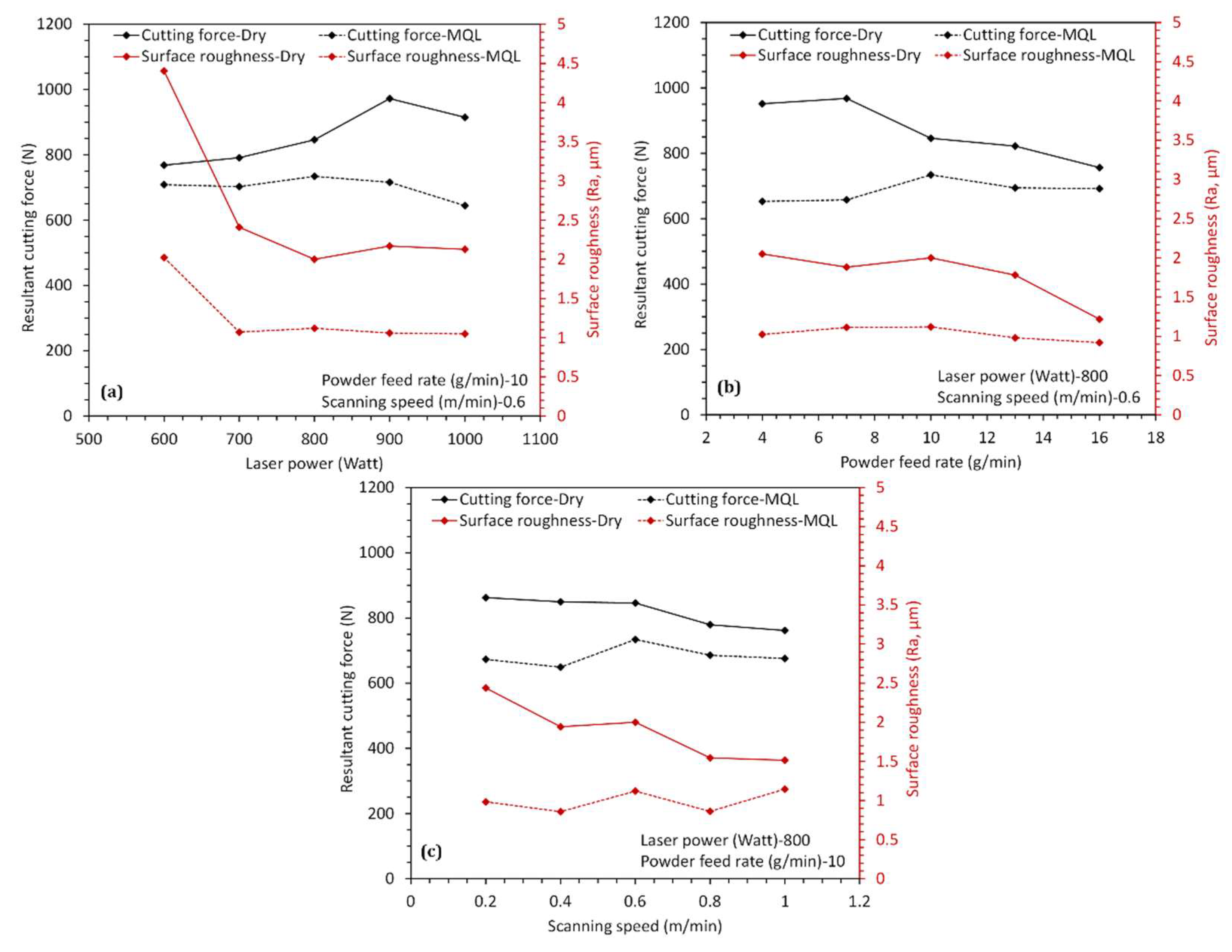
Figure 9a–c presents the variation in cutting forces and surface roughness with changes in LMD process parameters, viz., laser power, powder feed rate, and scanning speed, respectively. The variation is evaluated for machining of the bottom region of the LMDed IN718 walls in both dry and MQL cutting environments. With an increase in laser power, a simultaneous increase in cutting forces is observed for dry cutting (Figure 9a). The correlation between increased forces with laser power can be attributed to the rise in hardness values with laser power, as depicted in Figure 7. However, with the use of MQL the cutting forces remain constant despite an increase in laser power. Despite an increase in cutting forces with laser power for dry cutting, the surface roughness values remain relatively constant with an increase in laser power. The exceptionally high surface roughness value at a lower laser power of 600 W is a result of chatter. The chatter is attributable to the highly irregular as-deposited surface produced at a laser power of 600 W (see Figure 5a). Irrespective of the cutting environment, the machining of surfaces deposited at low laser power (600 W) triggers chatter. However, further studies are needed to examine the technical reasons behind this phenomenon in detail. Under the dry cutting environment, an increase in the scanning speed resulted in a slight decrease in cutting forces (Figure 9c).
At the same time, a more significant reduction was observed with an increase in the powder feed rate (Figure 9b). The slight decrease in the cutting forces achieved by increasing the scanning speed had a remarkably positive effect on surface quality, allowing for a substantial reduction in surface roughness. Similarly, lower forces at a higher powder feed rate improved the surface quality as expected, indicating that surface quality is enhanced at a higher powder feed rate and scanning speed. It is, however, crucial to note that this observed improvement is a mid-value of laser power (800 W). Both powder feed rate and scanning speed determine the quantity of the powder delivered to the molten pool and the Intensity of the laser energy absorbed by the powder in unit time. These two parameters dominate the height and width of the deposited layers and, thereby, the surface irregularity. It is, however, very important to keep these values under a certain limit as beyond threshold values, the laser irradiation energy is not enough to entirely melt the powder and form a stable molten pool [38]. With MOL, both the power feed rate and scanning speed had little to no effect on both the cutting forces and surface roughness. There is, however, a jump in the cutting forces when the powder feed rate is increased from 8 to 10 m/min and the scanning speed is increased from 0.4 to 0.6 m/min, both at a constant laser power of 800 W. Under MQL, a significant improvement in terms of surface roughness is observed at the highest powder feed rate of 16 g/min (scanning speed 0.6 m/min). In LMD, the increased interaction of the powder feed and laser beam has the most beneficial effect on the deposited surface quality. These two parameters control the catchment, i.e., the ratio of powder feed rate and scanning speed in LMD. At a higher powder feed rate, the amount of catchment is high, and the interaction between powder and laser beam increases [39], which consequently leads to a surface with improved quality and inherently eases the machining.
The employment of cutting fluid during machining may lead to numerous health risks and environmental effects. Complete elimination of cutting fluids through dry machining is challenging for difficult-to-machine IN718 alloy as observed from the results in Figure 8 and Figure 9. MQL is a suitable alternative to both dry and wet machining (i.e., flood cooling) as it not only lowers the consumption of cutting fluids, thereby reducing the occupational health hazards on the shop floor [40], without making any compromise on the surface quality of the machined surface (refer to Figure 8 and Figure 9). MQL is not only an environmentally friendly machining process [41] but also economical as it significantly cuts down on the cutting fluid usage, as well as MQL can be easily implemented with limited changes to the existing machinery.

3.3.3. Tool Wear

Tool wear is a critical failure mechanism that not only influences the quality of the final product, but also the overall sustainability of the process in terms of energy consumption and manufacturing costs. Defining and mitigating tool wear is crucial for the success of the additive–subtractive manufacturing (ASM) process chain. In this work, the different wear modes occurring on the cutting inserts in the machining experiments were analyzed. The examination of tool wear is first conducted after the machining of the top region before proceeding to the bottom region of the deposited IN718 walls. However, as no significant tool wear is observed during the machining of the top region, the final measurement of tool wear is carried out after the machining of the bottom region. During machinability evaluation experiments, it was observed that some tools broke during the cutting process, either in the middle of the cut or during the exit from the part. The breakage of cutting inserts can be directly attributed to the vibration-induced chatter that causes a sudden and significant change in the load acting on the insert. Images of the cutting inserts that broke during the machining experiments are depicted in Figure 10. At the lowest laser power of 600 W, a significant portion of the cutting insert broke, indicative of a high degree of chatter, which is also reflected in high surface roughness in Figure 9a. The abrasion resulting from the contact between the tool and the machined surface leads to chipping and catastrophic failure.
Figure 11, Figure 12 and Figure 13 compare the tool wear, i.e., the tool life for machining of LMDed IN718 wall with variation in laser power, powder feed rate, and scanning speed, respectively, under both dry and MQL cutting environments. Representative images of the cutting tools with different tool wear modes are also presented in Figure 11, Figure 12 and Figure 13. Similar to the observed increase in cutting forces and surface roughness with an increase of laser power, the tool wear also increases when laser power is increased from 600 to 1000 W (Figure 11). Although the application of MQL reduces the overall tool wear compared to dry cutting, the tool wear still increases at higher laser powers. The steep increase in tool wear at a laser power of 900 W under MQL is caused by two simultaneous wear phenomena, i.e., coating delamination and edge chipping, as represented in Figure 11a1. At a similar laser power, the tool under dry cutting has slightly higher tool wear and the presence of microchipping at the cutting edge, as seen in Figure 11a2. The contrasting behavior of tool wear with change in cutting environment at the highest laser power of 1000 W can be accounted for by the difference in wear modes. At the highest laser power of 1000 W, there is a sharp increase in the hardness of the deposited IN718, as shown in Figure 7. In dry cutting, due to the absence of sufficient cooling combined with the steep increase in hardness for the sample at 1000 W, the cutting insert is subjected to thermal cracking, as evident from Figure 11a4 where significant edge chipping is observed. The deleterious effect of increased hardness (at a laser power of 1000 W) on tool wear is alleviated in MQL due to effective cooling, the same being evident in (Figure 11a3), where no visible defect is observed in the cutting tool. This is also in accordance with the observed reduction in cutting forces and surface roughness for machining of the LMDed IN718 wall (fabricated at a laser power of 1000 W) under MQL (see Figure 9a). The chipping could be due to the detachment of fragments of the cutting insert edge, initiated by the adhesive wear mechanism [24]. A detailed study of the underlying wear mechanisms is the subject of future work. It can be stated that despite the increase in hardness with higher laser powers, the use of MQL enables the production of surfaces with higher quality and lower cutting forces. The lower cutting forces lead to a decrease in the cutting temperature (see Figure 8) and contribute to the tool wear reduction.
Figure 12 presents the variation in the tool wear with changes in the powder feed rate. Unlike the decrease in cutting forces and surface roughness with an increase in powder feed rate, the tool wear does not follow a particular trend. For powder feed rate, until 7 g/min, the tool wear remains constant for both dry and MQL, with dry cutting registering higher wear. A comparison of the wear modes in dry and MQL environments at a powder feed rate of 7 g/min is presented in Figure 12a1,a2, respectively. While MQL machining resulted in a tool with no visible defects (Figure 12a1), the dry cutting resulted in microchipping (Figure 12a2) and correspondingly higher wear. With an increase of powder feed rate to 10 g/min, the tool wear increased in dry cutting, which does not correspond to the decrease in cutting force and roughness observed previously. Although further experiments are required to elucidate the exact reason, the post-machining analysis of the tool reveals edge chipping (Figure 12a4), which can contribute to the observed jump in the wear. The inspection of the tool used for machining the IN718 wall fabricated at the same powder feed rate (10 g/min) under MQL reveals no defects (Figure 12a3), explaining the lower wear as compared to the dry cutting. Above the powder feed rate of 10 g/min, the tool wear reduces, which possibly is a result of the increase in the powder catchment and its positive effect on surface quality, as explained in the preceding section.
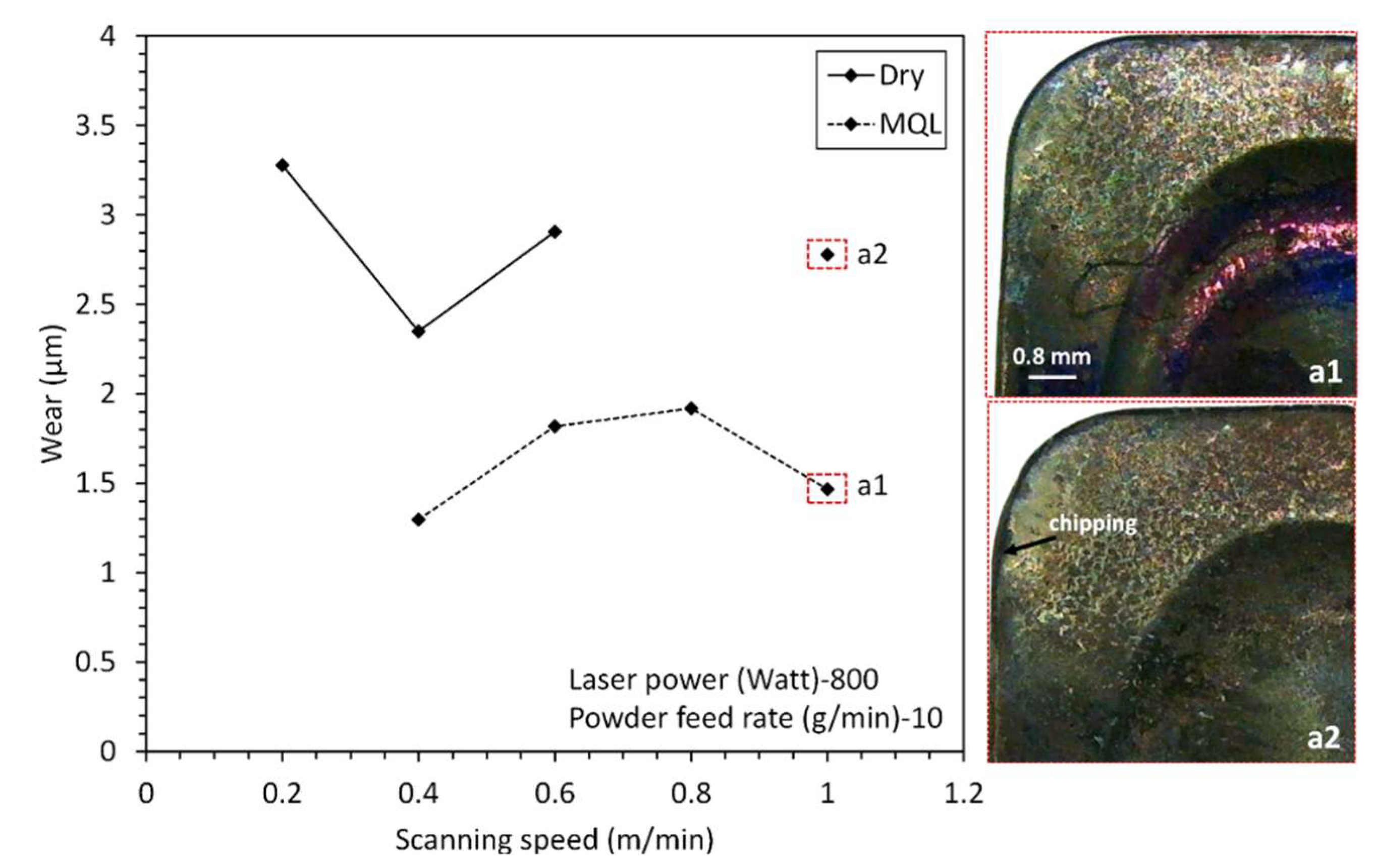
The scanning speed works in collusion with the powder feed rate in determining the surface quality of the as-deposited part, which in turn controls the tool wear. For a constant powder feed rate, the powder catchment starts decreasing beyond a certain scanning speed. In other words, the laser irradiation that is responsible for creating the melt pool may not be enough, leading to the uncompleted melting of powder particles and, consequently, an irregular surface. Machining of an irregular surface is expected to produce higher tool wear, as seen in Figure 13. The trend is prominent with MQL machining up to a scanning speed of 0.8 m/min. Representative images of tools post-machining of IN718 walls at the highest scanning speed of 1 m/min under MQL and dry environment are presented in Figure 13a1,a2. The almost double-reported wear in dry cutting is discernable from the tool wear modes, with the tool under MQL displaying no defects, whereas the tool used in dry cutting produced chipping at the cutting edge. Considering the observations, it is recommended to use a combination of a higher powder feed rate and a lower scanning speed with MQL to reduce the tool wear and ease the machining of IN718 walls.
One of the primary reasons for the reduced machining performance of IN718 alloy is the tool wear [14], and hence, an adequate understanding of the tool wear is critical from the industrial perspective. Due to the low thermal conductivity of IN718, the majority of the machining-generated heat is transferred to the cutting tool, leading to high tool tip temperatures and excessive tool wear [42]. In this work, the application of MQL for machining of LMDed IN718 walls reduced the surface temperatures (Figure 8c), leading to lower tool wear (Figure 11, Figure 12 and Figure 13) compared to dry machining. However, as tool wear is a complex interplay of several mechanisms (abrasive, adhesion, diffusion, oxidation, debonding), the influence of MQL on tool wear is not as significant compared to cutting forces and surface quality. Although under MQL machining, the tool wear remained lower compared to dry machining, the variability in tool wear with changes in LMD parameters remains, and in many cases, the tool wear in dry and MQL environments are comparable (Figure 11, Figure 12 and Figure 13). Nevertheless, further optimization of the MQL machining for LMDed IN718 will greatly benefit the industrial applications, as reduced tool wear consequently brings down the cost and waste during the production chain.

3.3.4. Energy Consumption

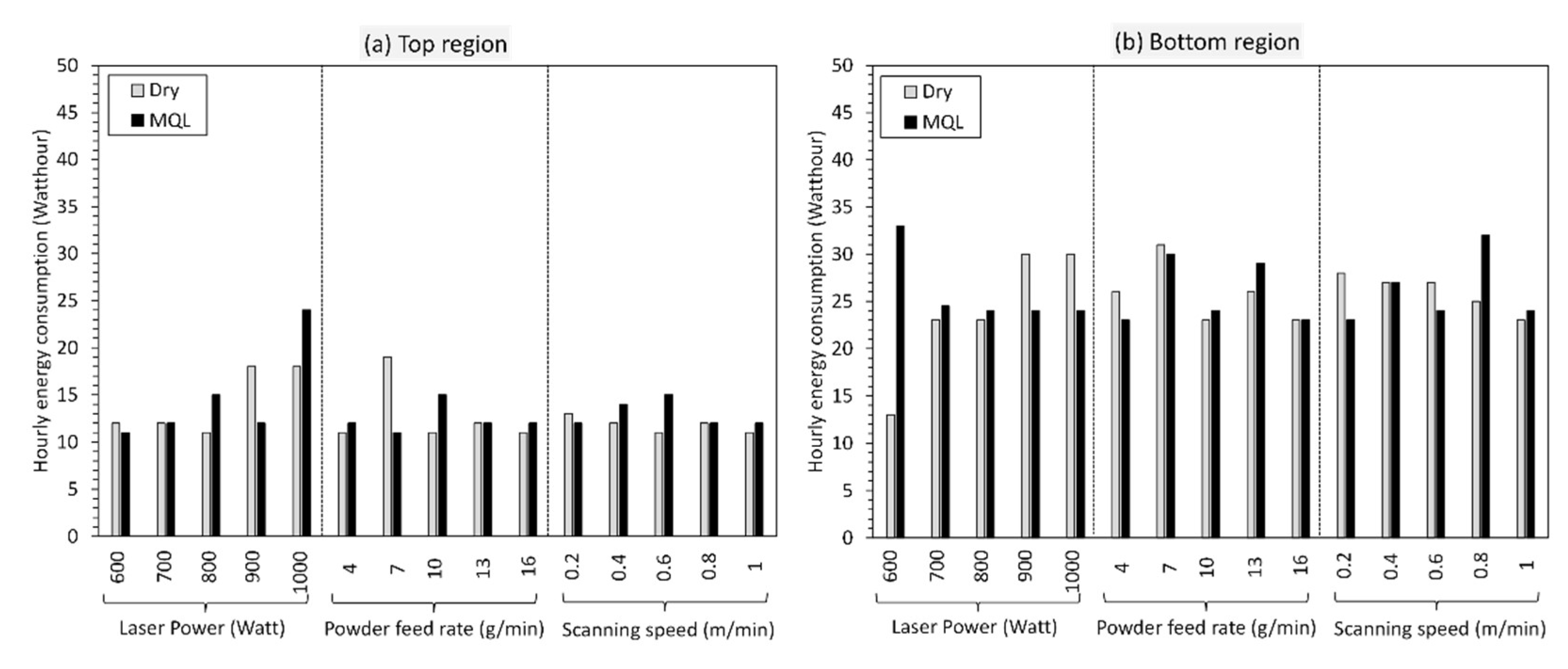
The energy consumption during machining is influenced by several factors, including the workpiece and tool materials, cutting conditions, and the cutting fluids or lubricants used [43]. Evaluating the effects of the cutting environment on energy consumption is essential for achieving a sustainable and high-quality ASM process chain. The analysis presented in Figure 14 aims to help understand the energy requirements for machining different regions of LMDed IN718 walls under dry and MQL cutting environments. It is quite clear from Figure 14 that the energy consumption while machining the top region of the IN718 wall remains significantly lower than the bottom region, irrespective of the cutting environment. This observation is valid across the entire range of experimental process parameters. While MQL positively impacts machinability in terms of reduced cutting forces, surface roughness, surface temperature, and tool wear, particularly in the bottom region, the use of MQL setup does not adversely affect the hourly energy consumption. From Figure 14, it is apparent that the hourly energy consumption remains comparable to dry cutting even while machining the bottom region. Moreover, MQL machining consumes lower energy while machining the bottom region of the IN718 walls fabricated at the highest laser powers of 900 and 1000 W. This is critical as higher laser powers not only increase the hardness of the part, but also lead to higher cutting forces (Figure 9) and tool wear (Figure 11). The steep energy consumption observed for MQL machining for walls fabricated at laser power 600 W correlates with the chatter phenomena, which also resulted in higher surface roughness and catastrophic failure of the tool, as discussed earlier in Section 3.3.2 and Section 3.3.3, respectively. These outcomes hold paramount significance for the ASM process chain. The potential economic benefits of MQL machining in terms of tool longevity (refer to Section 3.3.3) without a substantial increase in energy costs are significant, with positive implications for incorporating MQL in LMD and several other advanced AM and conventional manufacturing processes.

4. Conclusions and Future Directions

In this work, a comprehensive assessment of the machinability of laser metal deposited (LMDed) IN718 walls in dry and minimum quantity lubrication (MQL) cutting environments was performed. An understanding of the interplay of LMD process variables (laser power, powder feed rate, and scanning speed) and the cutting environment and its effect on the machining aspects, including cutting forces, tool wear, surface quality, and energy consumption, was developed. Based on the obtained results, the study reached the following major conclusions:
  • The machinability of the LMDed IN718 wall is location-dependent owing to the build direction hardness heterogeneity. The bottom region of the IN718 wall, i.e., the initially deposited layers, with considerably higher hardness than the top region, makes machining of the deposited wall closer to the substrate notably more difficult than away from the substrate.
  • Machining of the bottom region leads to substantially higher cutting forces, surface roughness, and temperatures compared to the top region. In addition, while in the bottom region, the variation in these aspects across the entire LMD processing range is large, the variation is minimal in the top region.
  • The machinability of LMDed IN718 walls under a dry-cutting environment is inferior compared to MQL machining along the entire build direction. MQL greatly improves machining across all processing parameters regardless of the machining location; however, the effect is more pronounced in the bottom region.
  • While MQL positively impacts machinability and reduces tool wear to a great extent, the hourly energy consumption remains comparable to dry cutting. This finding holds significance for the ASM process chain, as the negligible increase in hourly energy consumption can largely compensate for the cost of the MQL setup and other accessories.
  • Laser power is identified as the parameter that most influences the processing performance. The variation in powder feed rate and scanning speed has little-to-no effect on the cutting force, whereas the increase in laser power significantly increases the cutting forces. Higher laser powers are detrimental, as they contribute to higher hardness and lead to higher surface roughness. In comparison, a combination of a higher power feed rate and lower scanning speed is essential for ease of machining.
AM using LMD is a potential route for successfully fabricating several multi-material combinations. Although this investigation provides applicable solutions for post-processing, the fabricated IN718 parts, challenges such as chatter and adhesive behavior affecting tool wear and surface quality must also be addressed. Research should be directed toward optimizing the post-processing with a larger view of improved efficiency and sustainability. Even though the LMD AM of IN718 looks promising, challenges like low manufacturing speed and build volumes hinder its growth. However, these challenges can be outweighed by the inherent ability of the LMD process to form intricate shapes with high design flexibility, reshape existing objects, and the potential for repair applications that can lead to tremendous savings in terms of material, cost, and lead time.

Author Contributions

Conceptualization—Y.S. and A.S.; Formal Analysis—O.C.O., A.K.; Funding acquisition—T.S. and A.S., Investigation—O.C.O., A.K., Y.S., Y.H., K.I., S.K. and M.B.; Methodology—O.C.O., A.K., Y.S., Y.H., K.I., S.K., M.B. and A.S.; Project Administration—A.S., T.S. and M.T.; Resources—A.S. and M.T.; Supervision—A.S.; Visualization—A.K. and O.C.O.; Writing—Original Draft—O.C.O. and A.K.; Writing—Review and Editing—S.K., M.B. and A.S. All authors have read and agreed to the published version of the manuscript.

Funding

This research received no external funding.

Data Availability Statement

The raw/processed data required to reproduce these findings cannot be shared as the data also forms part of an ongoing study.

Acknowledgments

The authors would like to acknowledge the support of research group members for help in conducting experiments.

Conflicts of Interest

The authors declare that they have no known competing financial interest or personal relationships that could have influenced the work reported in this paper.

Nomenclature

Abbreviations:
LMDLaser metal deposition
DEDDirected energy deposition
AMAdditive manufacturing
MQLMinimum quantity lubrication
SSStainless steel
LDEDLaser-directed energy deposition
ASMAdditive–subtractive manufacturing
LMDedLaser metal deposited
FGMFunctionally graded material
Symbols:
VcCutting speed (m/min)
fzFeed per tooth (mm/tooth)
apDepth of cut (mm)
aeCutting width (mm)
GTemperature gradient
RSolidification growth rate
HIHeat input (J/m)
PLaser power (Watt)
VScanning speed (m/min)

Appendix A

For the removal of the unmelted powder particles and generating a flat surface for the machinability evaluation, all the as-deposited parts are scanned using a structural light scanner (ATOS Compact Scan, GOM Metrology). As shown in Figure A1a, with the 3D data of the scanned samples, the depth of the cut values is determined by finding the deviations. The pre-treatment, i.e., initial machining, ensured that the unmelted powder was removed without changing the effective width of the test piece. The initial machining to remove the unmelted powder particles is conducted with Mitsubishi AOMT123608PEER-M VP15TF grade PVD-coated carbide cutting inserts. As depicted in Figure A1b, the as-deposited irregular surfaces (with unmelted powder particles) are processed and made ready for the subsequent machinability evaluation study.
Figure A1. (a) Three-dimensional-scanned surface for the determination of the machining depth of cut; and (b) representative sample showing surfaces before and after the removal of unmelted powder particles.
Lubricants 11 00523 g0a1

References

  1. Wang, X.; Jiang, J.; Tian, Y. A review on macroscopic and microstructural features of metallic coating created by pulsed laser material deposition. Micromachines 2022, 13, 659. [Google Scholar] [CrossRef] [PubMed]
  2. Gu, D.D.; Meiners, W.; Wissenbach, K.; Poprawe, R. Laser additive manufacturing of metallic components: Materials, processes and mechanisms. Int. Mater. Rev. 2012, 57, 133–164. [Google Scholar] [CrossRef]
  3. Arrizubieta, J.I.; Cortina, M.; Ruiz, J.E.; Lamikiz, A. Combination of laser material deposition and laser surface processes for the holistic manufacture of inconel 718 components. Materials 2018, 11, 1247. [Google Scholar] [CrossRef] [PubMed]
  4. Cheng, J.; Xing, Y.; Dong, E.; Zhao, L.; Liu, H.; Chang, T.; Chen, M.; Wang, J.; Lu, J.; Wan, J. An overview of laser metal deposition for cladding: Defect formation mechanisms, defect suppression methods and performance improvements of laser-cladded layers. Materials 2022, 15, 5522. [Google Scholar] [CrossRef]
  5. Mazzucato, F.; Menerini, M.; Valente, A. Laser-based Hybrid System for Inconel 718 part repairing. Procedia CIRP 2020, 95, 29–34. [Google Scholar] [CrossRef]
  6. Dadbakhsh, S.; Hao, L.; Kong, C.Y. Surface finish improvement of LMD samples using laser polishing. Virtual Phys. Prototyp. 2010, 5, 215–221. [Google Scholar] [CrossRef]
  7. Rombouts, M.; Maes, G.; Hendrix, W.; Delarbre, E.; Motmans, F. Surface finish after laser metal deposition. Phys. Procedia 2013, 41, 810–814. [Google Scholar] [CrossRef]
  8. Ostra, T.; Alonso, U.; Veiga, F.; Ortiz, M.; Ramiro, P.; Alberdi, A. Analysis of the machining process of inconel 718 parts manufactured by laser metal deposition. Materials 2019, 12, 2159. [Google Scholar] [CrossRef]
  9. Rosa, B.; Mognol, P.; Hascoët, J.Y. Laser polishing of additive laser manufacturing surfaces. J. Laser Appl. 2015, 27, S29102. [Google Scholar] [CrossRef]
  10. Maffia, S.; Chiappini, F.; Maggiani, G.; Furlan, V.; Guerrini, M.; Previtali, B. Enhancing productivity and efficiency in conventional laser metal deposition process for Inconel 718–Part II: Advancing the process performance. Int. J. Adv. Manuf. Technol. 2023, 129, 279–298. [Google Scholar] [CrossRef]
  11. Paulonis, D.F.; Schirra, J.J. Alloy 718 at Pratt & Whitney–Historical perspective and future challenges. Superalloys 2001, 718, 13–23. [Google Scholar]
  12. Mazzucato, F.; Forni, D.; Valente, A.; Cadoni, E. Laser metal deposition of Inconel 718 alloy and as-built mechanical properties compared to casting. Materials 2021, 14, 437. [Google Scholar] [CrossRef] [PubMed]
  13. Shokrani, A.; Dhokia, V.; Newman, S.T. Environmentally conscious machining of difficult-to-machine materials with regard to cutting fluids. Int. J. Mach. Tools Manuf. 2012, 57, 83–101. [Google Scholar] [CrossRef]
  14. Yin, Q.; Liu, Z.; Wang, B.; Song, Q.; Cai, Y. Recent progress of machinability and surface integrity for mechanical machining Inconel 718: A review. Int. J. Adv. Manuf. Technol. 2020, 109, 215–245. [Google Scholar] [CrossRef]
  15. Bagherzadeh, A.; Budak, E.; Ozlu, E.; Koc, B. Machining behavior of Inconel 718 in hybrid additive and subtractive manufacturing. CIRP J. Manuf. Sci. Technol. 2023, 46, 178–190. [Google Scholar] [CrossRef]
  16. Shu, L.; Cang, X.; Zhou, J.; Heng, Z.; Wu, H.; He, W. Study on machinability and grain deformation of laser cladding manufactured and wrought IN718 alloys in dry milling process. Mater. Today Commun. 2023, 34, 105066. [Google Scholar] [CrossRef]
  17. Zhao, Y.; Han, X.; Xu, Z.; Sun, Y.; Meng, W. Influence of Thermogenetic Effect on Machinability of IN718 Alloy Made by Additive–Subtractive Integrated Manufacturing. J. Mater. Eng. Perform. 2023, 32, 1–19. [Google Scholar] [CrossRef]
  18. Li, B.; Zhang, R.; Malik, A.; Li, W. Machinability of partition milling stainless steel/Inconel functionally gradient material printed with directed energy deposition. Int. J. Adv. Manuf. Technol. 2022, 122, 3009–3022. [Google Scholar] [CrossRef]
  19. Zhang, R.; Nagaraja, K.M.; Bian, N.; Fisher, E.; Ahmadyar, S.; Bayazitoglu, K.; Lu, H.; Li, W. Experimental studies on fabricating functionally gradient material of stainless steel 316L-Inconel 718 through hybrid manufacturing: Directed energy deposition and machining. Int. J. Adv. Manuf. Technol. 2022, 120, 7815–7826. [Google Scholar] [CrossRef]
  20. Souflas, T.; Bikas, H.; Ghassempouri, M.; Salmi, A.; Atzeni, E.; Saboori, A.; Brugnetti, I.; Valente, A.; Mazzucato, A.; Stavropoulos, P. A comparative study of dry and cryogenic milling for Directed Energy Deposited IN718 components: Effect on process and part quality. Int. J. Adv. Manuf. Technol. 2022, 119, 745–758. [Google Scholar] [CrossRef]
  21. Heigel, J.C.; Phan, T.Q.; Fox, J.C.; Gnaupel-Herold, T.H. Experimental investigation of residual stress and its impact on machining in hybrid additive/subtractive manufacturing. Procedia Manuf. 2018, 26, 929–940. [Google Scholar] [CrossRef]
  22. Oyelola, O.; Crawforth, P.; M’Saoubi, R.; Clare, A.T. Machining of additively manufactured parts: Implications for surface integrity. Procedia CIRP 2016, 45, 119–122. [Google Scholar] [CrossRef]
  23. Pereira, J.C.; Zubiri, F.; Garmendia, M.J.; Tena, M.; Gonzalez, H.; López de Lacalle, L.N. Study of laser metal deposition additive manufacturing, CNC milling, and NDT ultrasonic inspection of IN718 alloy preforms. Int. J. Adv. Manuf. Technol. 2022, 120, 2385–2406. [Google Scholar] [CrossRef]
  24. Careri, F.; Umbrello, D.; Essa, K.; Attallah, M.M.; Imbrogno, S. The effect of the heat treatments on the tool wear of hybrid Additive Manufacturing of IN718. Wear 2021, 470, 203617. [Google Scholar] [CrossRef]
  25. Calleja, A.; Urbikain, G.; González, H.; Cerrillo, I.; Polvorosa, R.; Lamikiz, A. Inconel® 718 superalloy machinability evaluation after laser cladding additive manufacturing process. Int. J. Adv. Manuf. Technol. 2018, 97, 2873–2885. [Google Scholar] [CrossRef]
  26. Kelliger, T.; Schraknepper, D.; Bergs, T. Fundamental investigations on the machinability of additively manufactured multi-materials. MM Sci. J. 2021, 5098–5105. [Google Scholar] [CrossRef]
  27. Zhou, H.; Yang, Y.; Han, C.; Wei, Y.; Liu, Z.; Tai, Z.; Zhang, S.; Wang, D. Laser directed energy deposition/milling hybrid additive manufacturing of thin-walled GH4169 alloy: Effect of processing strategy on its microstructure and mechanical properties. Mater. Sci. Eng. A. 2023, 882, 145480. [Google Scholar] [CrossRef]
  28. Gupta, M.K.; Boy, M.; Korkmaz, M.E.; Yaşar, N.; Günay, M.; Krolczyk, G.M. Measurement and analysis of machining induced tribological characteristics in dual jet minimum quantity lubrication assisted turning of duplex stainless steel. Measurement 2022, 187, 110353. [Google Scholar] [CrossRef]
  29. Nadammal, N.; Kromm, A.; Saliwan-Neumann, R.; Farahbod, L.; Haberland, C.; Portella, P.D. Influence of support configurations on the characteristics of selective laser-melted inconel 718. JOM 2018, 70, 343–348. [Google Scholar] [CrossRef]
  30. Banerjee, N.; Sharma, A. Development of a friction model and its application in finite element analysis of minimum quantity lubrication machining of Ti-6Al-4 V. J. Mater. Process. Technol. 2016, 238, 181–194. [Google Scholar] [CrossRef]
  31. Jang, D.Y.; Jung, J.; Seok, J. Modeling and parameter optimization for cutting energy reduction in MQL milling process. Int. J. Precis. Eng. Manuf.—Green Technol. 2016, 3, 5–12. [Google Scholar] [CrossRef]
  32. Ozaner, O.C.; Klobčar, D.; Sharma, A. Machining Strategy Determination for Single-and Multi-Material Wire and Arc Additive Manufactured Thin-Walled Parts. Materials 2023, 16, 2055. [Google Scholar] [CrossRef] [PubMed]
  33. Tian, Y.; McAllister, D.; Colijn, H.; Mills, M.; Farson, D.; Nordin, M.; Babu, S. Rationalization of microstructure heterogeneity in INCONEL 718 builds made by the direct laser additive manufacturing process. Metall. Mater. Trans. A 2014, 45, 4470–4483. [Google Scholar] [CrossRef]
  34. Stevens, E.L.; Toman, J.; To, A.C.; Chmielus, M. Variation of hardness, microstructure, and Laves phase distribution in direct laser deposited alloy 718 cuboids. Mater. Des. 2017, 119, 188–198. [Google Scholar] [CrossRef]
  35. Li, Z.; Chen, J.; Sui, S.; Zhong, C.; Lu, X.; Lin, X. The microstructure evolution and tensile properties of Inconel 718 fabricated by high-deposition-rate laser directed energy deposition. Addit. Manuf. 2020, 31, 100941. [Google Scholar] [CrossRef]
  36. Reddy, S.; Kumar, M.; Panchagnula, J.S.; Parchuri, P.K.; Kumar, S.S.; Ito, K.; Sharma, A. A new approach for attaining uniform properties in build direction in additive manufactured components through coupled thermal-hardness model. J. Manuf. Process. 2019, 40, 46–58. [Google Scholar] [CrossRef]
  37. Alhuzaim, A.; Imbrogno, S.; Attallah, M.M. Controlling microstructural and mechanical properties of direct laser deposited Inconel 718 via laser power. J. Alloys Compd. 2021, 872, 159588. [Google Scholar] [CrossRef]
  38. Zhang, K.; Liu, W.; Shang, X. Research on the processing experiments of laser metal deposition shaping. Opt. Laser Technol. 2007, 39, 549–557. [Google Scholar] [CrossRef]
  39. Moradi, M.; Pourmand, Z.; Hasani, A.; Moghadam, M.K.; Sakhaei, A.H.; Shafiee, M.; Lawrence, J. Direct laser metal deposition (DLMD) additive manufacturing (AM) of Inconel 718 superalloy: Elemental, microstructural and physical properties evaluation. Optik 2022, 259, 169018. [Google Scholar] [CrossRef]
  40. Banerjee, N.; Sharma, A. A comprehensive assessment of minimum quantity lubrication machining from quality, production, and sustainability perspectives. Sustain. Mater. Technol. 2018, 17, e00070. [Google Scholar] [CrossRef]
  41. Sharma, V.S.; Singh, G.; Sørby, K. A review on minimum quantity lubrication for machining processes. Mater. Manuf. Process. 2015, 30, 935–953. [Google Scholar] [CrossRef]
  42. Sugihara, T.; Enomoto, T. High speed machining of Inconel 718 focusing on tool surface topography of CBN tool. Procedia Manuf. 2015, 1, 675–682. [Google Scholar] [CrossRef]
  43. Muñoz-Escalona, P.; Shokrani, A.; Newman, S.T. Influence of cutting environments on surface integrity and power consumption of austenitic stainless steel. Robot. Comput.-Integr. Manuf. 2015, 36, 60–69. [Google Scholar] [CrossRef]
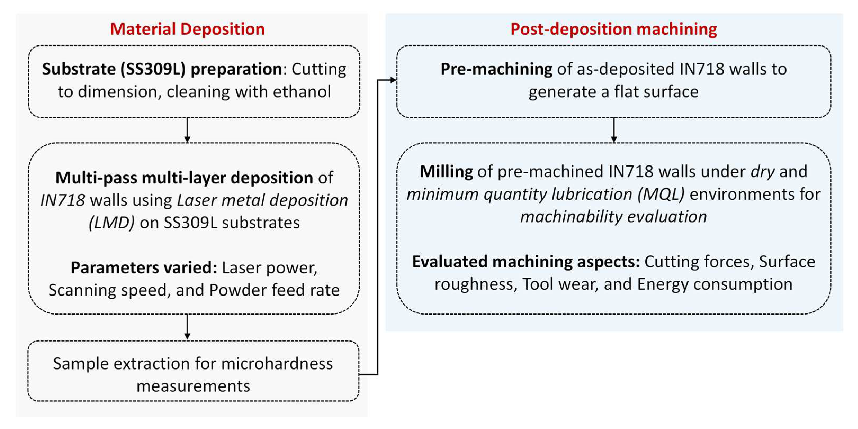
Figure 1. Flowchart depicting the experimental workflow.
Lubricants 11 00523 g001
Figure 2. (a) Deposition scheme for LMD; (b) geometry and dimensions of the SS 309L substrate and deposited IN718 wall; and (c) the location and dimensions of samples for machining and hardness measurement (Schematics not drawn to scale).
Lubricants 11 00523 g002
Figure 3. Experimental setup for machinability evaluation experiments.
Lubricants 11 00523 g003
Figure 4. (a) Representative resultant force–time plot for machining of sample deposited at the laser power, powder feed rate, and scanning speed of 800 Watt, 4 g/min and 0.6 m/min, respectively, (b) Representation of the maximum temperature measurement during machining. (Note: The commas in the (b) are used for decimal signs).
Lubricants 11 00523 g004
Figure 5. As-deposited IN718 walls at different laser powers.
Lubricants 11 00523 g005
Figure 6. (a) Hardness measurement perpendicular to the build direction in different regions of the LMDed IN718 wall, and (b) the actual sample depicting the location of the indents.
Lubricants 11 00523 g006
Figure 7. (a) Effect of laser power on hardness along the build direction for LMDed IN718 wall, and (b) the actual sample depicting the location of the indents.
Lubricants 11 00523 g007
Figure 8. Comparison of machining aspects in the top and bottom regions under dry and MQL cutting environments (a) Resultant cutting force, (b) surface roughness, and (c) maximum temperature.
Lubricants 11 00523 g008
Figure 9. Effect of (a) laser power, (b) powder feed rate, and (c) scanning speed on the resultant cutting forces and surface roughness for machining of the bottom region of the IN718 wall under dry and MQL cutting environments.
Lubricants 11 00523 g009
Figure 10. Images of the cutting tools that broke at the edges (shown in red boxes) during machining experiments.
Lubricants 11 00523 g010
Figure 11. Variation in tool wear with change in laser power. Representative images (a1a4) depict different tool wear modes corresponding to the process conditions highlighted in the graph.
Lubricants 11 00523 g011
Figure 12. Variation in tool wear with a change in powder feed rate. Representative images depicting different tool wear modes are also presented. Representative images (a1a4) depict different tool wear modes corresponding to the process conditions highlighted in the graph.
Lubricants 11 00523 g012
Figure 13. Variation in tool wear with a change in scanning speed. Representative images depicting different tool wear modes are also presented. Representative images (a1,a2) depict different tool wear modes corresponding to the process conditions highlighted in the graph.
Lubricants 11 00523 g013
Figure 14. Comparative analysis of hourly energy consumption under different cutting environments for the machining of (a) the top region and (b) the bottom region.
Lubricants 11 00523 g014
Table 1. LMD process parameters.
SampleLaser Power (W)Powder Feed Rate (g/min)Scanning Speed (m/min)Number of Layers *
1600100.656
2700100.652
3800100.652
4900100.652
51000100.640
680040.680
780070.656
8800100.652
9800130.632
10800160.632
11800100.214
12800100.425
13800100.652
14800100.868
15800101.094
* The number of layers represents the layers achieved to attain the fixed sample height, as shown in Figure 2b.
Table 2. Machining parameters.
Machining ParameterValue
Cutting speed, Vc (m/min)50
Feed per tooth, fz (mm/tooth)0.1
Depth of cut, ap (mm)0.8
Cutting width, ae (mm)10
Disclaimer/Publisher’s Note: The statements, opinions and data contained in all publications are solely those of the individual author(s) and contributor(s) and not of MDPI and/or the editor(s). MDPI and/or the editor(s) disclaim responsibility for any injury to people or property resulting from any ideas, methods, instructions or products referred to in the content.