1. Introduction
Since gears in aviation or wind turbine applications are exposed to high loads due to strong friction and wear caused by high local contact pressures, they are often surface treated to improve their wear resistance. There exist various research approaches to enhance wear resistance, such as thermochemical surface heat treatment [
1], coating [
2,
3], surface structuring [
4,
5], or a combination of these processes [
6].
To increase the wear resistance and minimize frictional losses of tribologically loaded components without the usage of common oil-based lubricants, solid lubricant coatings can be applied. One established method is the physical vapor deposition (PVD) of friction-reducing coating systems, such as graphite (C) or molybdenum disulfide (MoS
2) [
7,
8].
Both materials share a lamellar microstructure in which basal planes can easily slide against each other and thus reduce the coefficient of friction as well as wear on the coating and counterbody side [
9]. One of the main challenges of the PVD solid lubricant coating development is to ensure a good substrate adhesion. Therefore, MoS
2 is often combined with an interlayer such as Ti
XN [
3,
10,
11] on usually polished steel substrates.
Nitriding is a thermochemical surface heat treatment in which a hard and a few micrometers thick compound layer directly at the surface and an underlying diffusion or precipitation layer extending deeper into the material are formed by diffusing atomic nitrogen into the material. The formation of the compound layer on the surface and the depth of the diffusion layer depend significantly on the parameters of the nitriding process, in particular the temperature, time, and the nitriding potential of the atmosphere.
The structure and properties of the compound layer have a decisive influence on the tribological load-carrying capacity of the loaded surface in terms of wear and micro-pitting, whereas the diffusion layer leads to an increase in pitting and tooth root fatigue strength if the nitriding hardness depth (NHD) is sufficient [
12]. Nitriding is also a useful supplement for a hard coating, as it increases the surface hardness of the component and thus the support effect of the hard coating system applied. In addition, a defined nitriding layer formation can significantly improve the coating adhesion strength and thus increase the wear resistance [
2].
A defined nitride layer formation further means a controlled compound layer structure by influencing the phase composition, compound layer thickness (CLT), and pore seam thickness (CLT
P). The compound layer mainly consists of iron nitrides, whereas the diffusion layer is a zone characterized by precipitation of fine iron and alloy element-nitrides. The iron nitride phases ε and γ’ in the compound layer have different mechanical properties. For optimum wear behavior, the compound layer should have as high a proportion of ε-nitrides or ε-carbonitrides as possible [
13] since the ε-phase generally has a higher hardness due to its higher nitrogen content and crystallographic structure. The pore seam in the compound layer has been controversially discussed in the past in connection with its influence on the wear behavior. However, it has been shown that the pore seam may have a positive influence on the wear behavior of components since pores are able to absorb lubricants and thus ensure lower friction and wear in the event of insufficient lubrication conditions [
14,
15]. In addition, the higher initial wear of the pore seam ensures geometry adaptation of the contact surfaces, which can reduce local surface pressure [
14]. In recent investigations, the occurrence of micro-pitting could be prevented by creating a defined pore seam [
1].
The mechanisms for preventing wear by surface texturing are the trapping of wear particles and the storage of lubricants [
16,
17]. In the application of various deterministic surface structures on nc-ZrC/a-C:H coatings, Bobzin et al. identified a significant reduction of the coefficient of friction (CoF) for different gear wheel speeds under boundary and mixed friction conditions under elasto-hydrodynamic lubrication in rolling–sliding contacts [
18]. Even a selective laser texturing of PVD multi-layers—only in the top layer of the multi-layer system retaining the underlying layer or layers unaffected—is possible to apply precise structures with depth deviations of less than 0.2 μm without burrs or melt residues [
5]. Furthermore, texturing of ceramic coatings is possible by means of ultra-short pulse laser processing in order to create a defined surface topology with specific roughnesses or decorative structures [
19].
Hasselbruch et al. reported on multi-layered a-C:H:W/a-C:H coatings that were micro-structured by picosecond laser ablation [
20,
21,
22]. Different dimple diameters were directly introduced into the coating and then tribologically tested at a constant coating coverage of 60% in lubricated and lubricant-free pin-on-disc tests. Regardless of the laser surface texturing (LST), no coating wear could be detected for the lubricated conditions. In addition, very low friction and wear coefficients were determined for all LSTs under lubricant-free testing conditions. Optimal dimple diameters could be identified for both lubrication conditions. The good tribological properties could be attributed in each case to the dimples acting as lubricant or wear debris reservoirs [
20]. A comparable a-C:H(:W) coating system was deposited on different plasma-nitrided specimens made of AISI D2 cold working steel [
21,
22]. Duplex variants with and without compound layers were investigated by adjusting the N
2:H
2 gas ratios and the plasma nitriding times. A significant impact on the resulting surface topographies with respect to surface roughness (Sa, Spk, Svk) on coating adhesion strength was determined compared with all subsequently polished duplex surface conditions. However, all plasma variants with compound layers showed significantly increased coating adhesion (critical loads Lc2), as determined by scratch tests. Therefore, it is concluded that, in addition to the mechanical interlocking, the chemical composition of the ε- and γ’-nitride phases of the compound layer has a great impact on the coating adhesion.
The present study addresses the impact of different compound layer structures on the tribological behavior of duplex-treated material EN31CrMoV9 under dry conditions. For this purpose, the thickness, the porosity, and the phase composition of the compound layer was varied by the nitriding process conditions followed by the deposition of a MoS2:Ti monolayer PVD coating. Since the hardness of the diffusion layer also contributes to the mechanical support of the nitrided layer, differences in the diffusion zone are also considered in the discussion. The nitriding hardness depth was kept constant for all nitriding variants at approx. 0.8 mm in order to eliminate any influence by the case depth. To evaluate the wear behavior, the pin-on-disc test was used.
2. Materials and Methods
2.1. Sample Material and Geometry
The specimens were made of the nitriding and heat-treatable steel EN31CrMoV9 which is commonly used for nitrided gear applications. The chemical composition was measured via optical emission spectroscopy (OES) as follows: 0.33 wt% C, 0.21 wt% Si, 0.47 wt% Mn, 2.3 wt% Cr, 0.16 wt% Mo, and 0.12 wt% V. Square coupon specimens with a side length of 25 mm and a thickness of 8 mm were prepared from the material.
The specimens were oil-quenched from 870 °C and tempered for 2 h at 630 °C prior to the duplex surface treatment in order to achieve a sufficient strength in the core which is not affected by the nitriding or coating treatment. The hardness of the quenched and tempered specimens was approx. 310 HV10.
All specimens were barrel ground (trovalized) for about 24 h for surface activation and roughness reduction prior to nitriding.
2.2. Nitriding Treatments
A pit-type furnace with automated nitriding potential control was used for the gas nitriding treatments. Heating was carried out in an ammonia atmosphere to activate the surface of the specimens. Cooling after nitriding was carried out with the addition of ammonia (phase-controlled cooling) to avoid nitrogen effusion and the resulting denitriding at the end of the process.
The parameters for the nitriding processes to create compound layers with different thicknesses and structures were taken from earlier investigations [
23]. Four single-stage treatments and four double-stage treatments were performed according to
Table 1. The aim of the different nitriding processes was a variation of the compound layer thickness and porosity. To eliminate the influence of the nitriding hardness depth on the studies concerning the compound layer, the nitriding hardness depth was kept constant for all nitriding variants at approx. 0.8 mm.
The thickness of the compound layer and the porous zone was evaluated on metallographic cross-sections at 1000× magnification according to the test specification of the Arbeitsgemeinschaft Wärmebehandlung + Werkstoffechnik e. V. (AWT) [
24] by measuring at ten points on three micrographs. Additionally, the nitriding hardness depth was determined on the cross-section of the specimens in accordance with DIN 50190-3 (HV0.5) which was since replaced by the current standard DIN EN ISO 18203:2022-07. The hardness of the compound layers was not determined since the first reliable hardness imprint on the cross-section could be made only at a distance of 50 µm from the surface.
The phase composition of the compound layers was determined using XRD. X-ray diffraction patterns with Cr-Kα-radiation were recorded and the proportions of ε- and γ’-nitride were determined using the Rietveld method. In this method, the entire XRD pattern is considered as a mathematical function of the diffraction angle, which also depends on the crystal structure. Starting from an initial model of the atomic structure, the structural and instrumental parameters are continuously refined and the entire pattern is fitted. Since the penetration depth of the X-rays, defined as the depth to which the radiation intensity drops to 1/e, is limited to about 10 µm and the information about the phase fractions (based on an exponential function weighted according to depth) was included in the measured value, the information obtained in this way could be seen as an average phase composition for thicker compound layers.
The surface roughness Sa was determined by confocal laser microscopy using a VK-X1000 microscope of the brand Keyence (Keyence Deutschland GmbH Siemensstraße 1, D-63263 Neu-Isenburg, Germany). The chosen magnification was 50× and the Gaussian filters were set to λS = 0.8 µm and λL = 0.025 mm.
2.3. Coating Process
For this study, single-layer titanium-doped molybdenum disulfide (MoS
2:Ti) coatings were applied by reactive magnetron sputtering. Before the PVD-coating process, the specimens were cleaned in a fully automated ultrasonic solvent-based cleaning device with vacuum drying (Amsonic ECS40) [
2,
3].
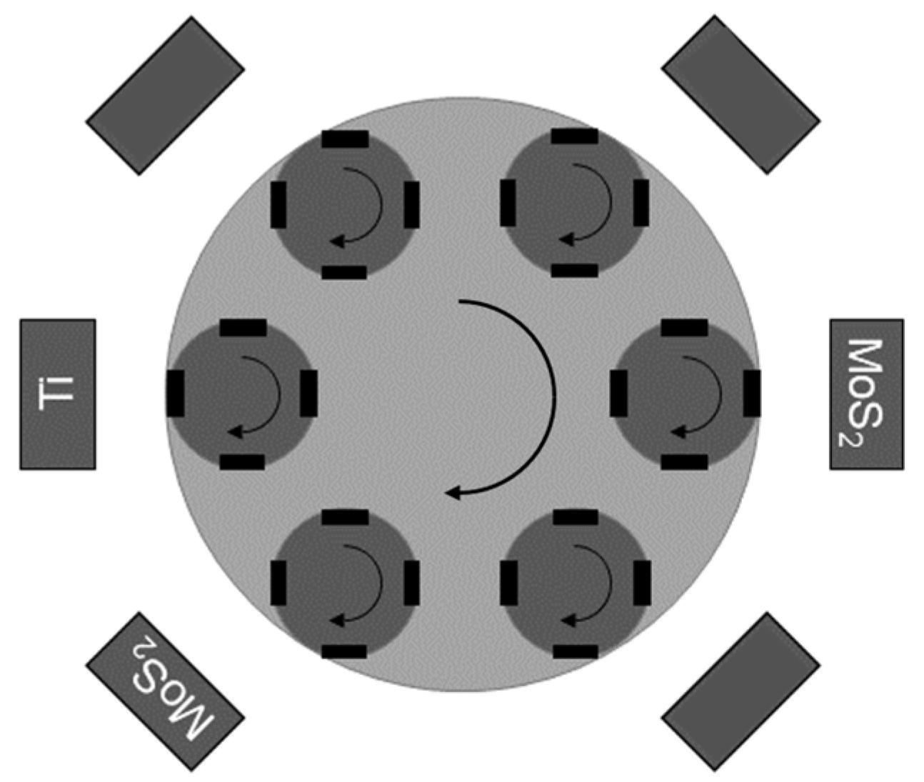
The coating process itself was structured in the phases of heating, plasma etching, coating deposition, and cooling. An industrial CemeCon CC800/9 HiPIMS PVD coating device (CemeCon AG Adenauerstraße 20 A4 52146 Würselen, Germany) was used, and the sputter target configuration is shown in
Figure 1. Of the six available cathode slots, only three were used: one MoS
2 target in DC mode as well as one MoS
2 and one Titan target in high-power impulse magnetron sputtering (HiPIMS) mode. The specimens were moved in double rotation as many rotationally symmetrical components such as gears are coated in this method, thus ensuring easier transferability.
Argon and Krypton were used as sputter gases, with a total pressure during the coating phase of 500 mPa. The target power was set to 500 W for each target, combined with a bias voltage of—100 V of the substrate table. A monolayer MoS
2:Ti of 1.2 µm thickness was produced due to the coating time of 6000 s. The hardness and elasticity of this solid lubricant film were measured by micro-indentation testing. In order to limit the maximum indention depth to 10% of the coating thickness according to DIN EN ISO 14577-1, the maximum indentation force was limited to 5 mN with 10 s of load-, hold-, and unloading times using a Fischerscope H100C Universal micro-hardness device (Helmut Fischer GmbH Institut für Elektronik und Messtechnik, Sindelfingen, Germany) [
25]. An indentation hardness H
IT0.05 of 7.32 ± 0.47 GPa, equaling a converted Vickers hardness of approx. 691 ± 44 HV, and an elastic indentation modulus E
IT0.05 of 138.1 ± 6.8 GPa were determined for the applied MoS
2:Ti coating. A reference variant using a 0.8 µm thick TiCN interlayer with a H
IT0.05 hardness of 11.09 ± 1.69 GPa and an elastic indentation modulus E
IT0.05 of 172.46 ± 13.30 GPa was additionally tested.
2.4. Investigation of the Wear Behavior
A rotational pin-on-disc tribometer (TRM100, Dr. Ing. Georg Wazau Mess- + Prüfsysteme GmbH Keplerstraße 12 10589 Berlin, Germany) was used for determining the tribological sliding properties. Roller bearing balls made of EN100Cr6 with a diameter of 10 mm were used as counter pin bodies for all tests. Two series of tests were conducted according to
Table 2. The pin-on-disc tests were stopped when the coefficient of friction increased to 0.5 or above or after a maximum of 40,000 turns.
In addition to the duplex-treated specimens, an uncoated sample of D2 and a two-layer coating system TiCN + MoS2:Ti on polished case-hardened EN18CrNiMo7-6 steel were tested as reference states.
The sliding distances resulting from the track radii and the number of cycles for the specimens of the different variants are summarized in
Table 3. Forty thousand cycles correspond to a sliding distance of 1259 m for the track radius of 5 mm and 2015 m for the track radius of 8 mm.
The tests were carried out under dry conditions without adding fluidic lubricants. Therefore, the pin-on-disc tests can be considered as mainly abrasive wear tests. The temperature of the specimens was not monitored during the experiments.
The wear scars on the pin and the cross-sections of the wear tracks of the duplex-treated samples were measured by confocal laser scanning microscopy (CLSM). The wear coefficients were determined from the wear volume and the friction distance in accordance with DIN EN 1071-13 and ASTM G99.
2.5. CNN-Based Determination of the MoS2:Ti Layer Adhesion
The adhesion strength of the solid lubricant layer in the nitrided specimens was determined by the Rockwell adhesion test according to VDI 3198 and DIN 4856. This test defines six adhesion classes (Haftungsklasse—HF), ranging from HF1 to HF6. The classification into the adhesion classes was performed by an automated system based on convolutional neural networks, as presented by Lenz et al. in 2020 [
26]. The evaluation system described in this paper was implemented for an inception-resnet-v2 CNN model [
27], reaching high classification accuracies of >90% compared with human evaluation, while remaining independent of subjective influence on the results. Nevertheless, the automatically generated results were cross-checked by the authors. For each investigated sample, six Rockwell imprints were set and evaluated.
3. Results
3.1. Variation of the Compound Layer
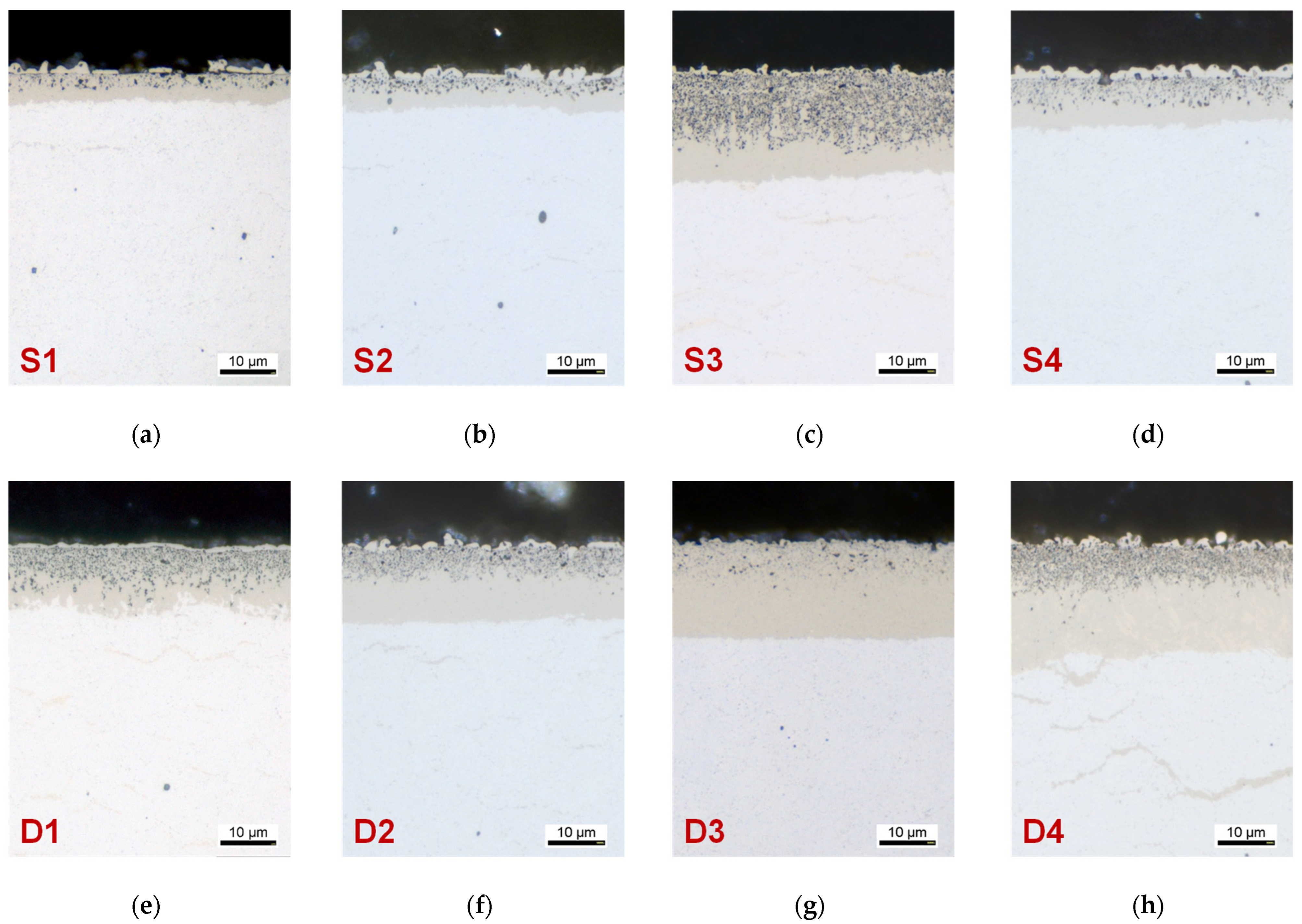
Figure 2 shows the cross-sections of the nitrided samples. No etching was applied to achieve a better representation of the pores within the compound layer. The results of the compound layer and pore area thickness measurements are summarized in
Table 4.
The different nitriding treatments produced compound layers with a thickness of 6–20 µm. All compound layers exhibited pores in the area close to the surface. The proportion of porosity in the compound layer was between 40% and 75%. The cross-sections showed that the pore seams not only varied in thickness and proportion but also in size and distribution. There was no correlation between the porosity and the surface roughness Sa measured by CLSM with a 500× magnification.
Figure 3 shows that the surface roughness values
Sa of the nitrided specimens ranged from 0.35 µm to 0.53 µm. Based on the determined roughness parameters and the cross-sections in
Figure 2, it is clear that the pores were significantly smaller than the irregularities of the sample surface and that the roughness, therefore, did not allow a description of the surface structure in terms of porosity.
The γ’-phase was predominantly detected in all compound layers, with the exception of treatment D4 where the final nitrocarburizing led to a significant increase in the ε-content in the compound layer.
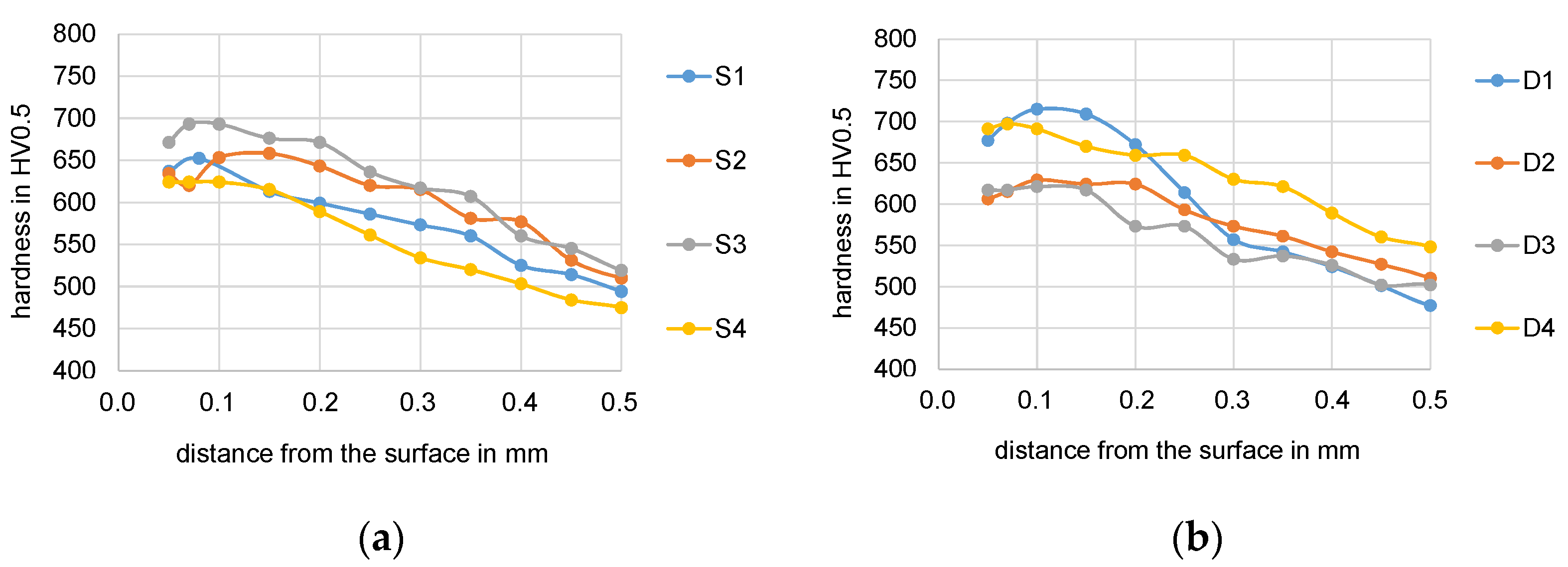
3.2. Hardness of the Diffusion Zone after Nitriding
Figure 4 shows the hardness curves of the first 0.5 mm after the different nitriding treatments. Comparing the one-step treatments, an increase in maximum hardness was observed with increasing nitriding potential for treatments S1, S2, and S3 that were all applied at a temperature of 530 °C. The single-stage treatments S2 and S4 were both carried out with a nitriding potential of K
N = 1. The higher temperature during treatment S4 resulted in a lower maximum hardness in the nitrided layer.
The two-stage treatments were carried out because this allowed better control of the compound layer growth and design. The fact that the two-stage process control also had an influence on the formation of the diffusion layer becomes particularly clear by comparing treatments D1 and D2, which differed only in the sequence of the process steps. In the first stage of process D1, to form the compound layer with a high nitriding potential, a diffusion depth of about 0.25 mm was achieved. This corresponded exactly to the range in which this variant exhibited a higher hardness than variant D2 where the nitrogen supply was first increased in the second step to form the compound layer. The treatments D3 and D4 focused on a variation of the compound layer by different nitriding parameters in the second process step. Nitrocarburizing in the second step of treatment D4 resulted in a higher hardness than for the nitrided-only variants D2 and D3 whose hardness profiles did not differ significantly.
In order to evaluate the support effect of the diffusion layer with respect to the compound layer and the MoS
2 coating, the hardness in the range of 50–100 µm was used. The hardness values given in
Table 5 at 50 µm and 100 µm distances from the surface were directly recorded from the cross-section. The mean values for 50–100 µm were calculated from three single hardness imprints at 50, 70, and 100 µm distances from each surface.
3.3. Layer Adhesion Classes
The mean adhesion class values resulting from six single measurements are presented alongside a reference variant using a PVD-deposited TiCN interlayer on polished case-hardened EN18CrNiMo7-6 steel substrate in
Figure 5. The adhesion class HF of the MoS
2:Ti solid lubricant coating applied on the different nitrided states ranges from 1.3 which means fine cracks and sometimes small, unconnected spallings to 2.3 where larger delaminations are allowed. Compared to the reference state where the MoS
2:Ti layer was deposited on a TiCN interlayer to enhance the adhesion strength, the adhesion of the duplex systems is on the same high level.
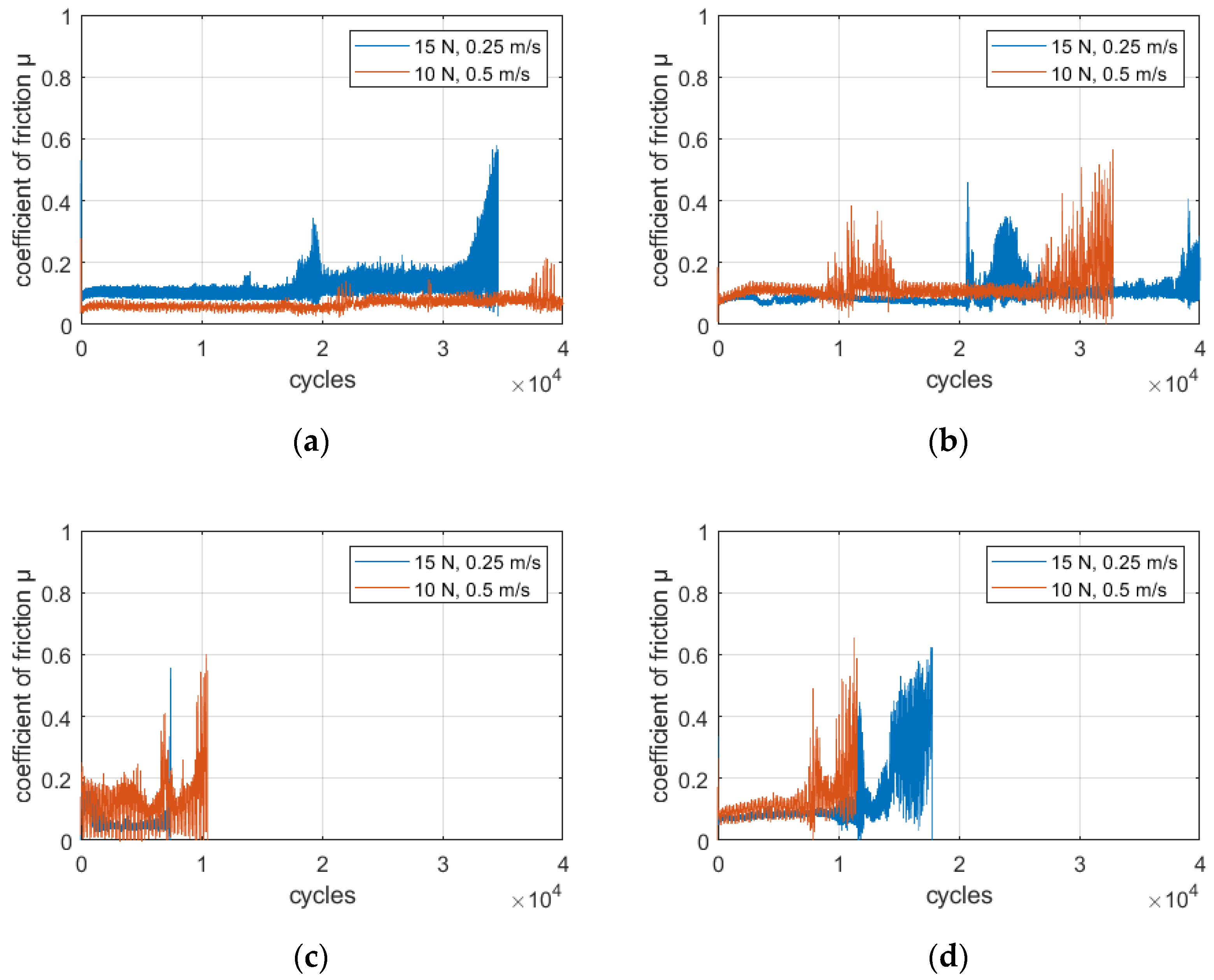
3.4. Coefficient of Friction from Pin-on-Disc Tests
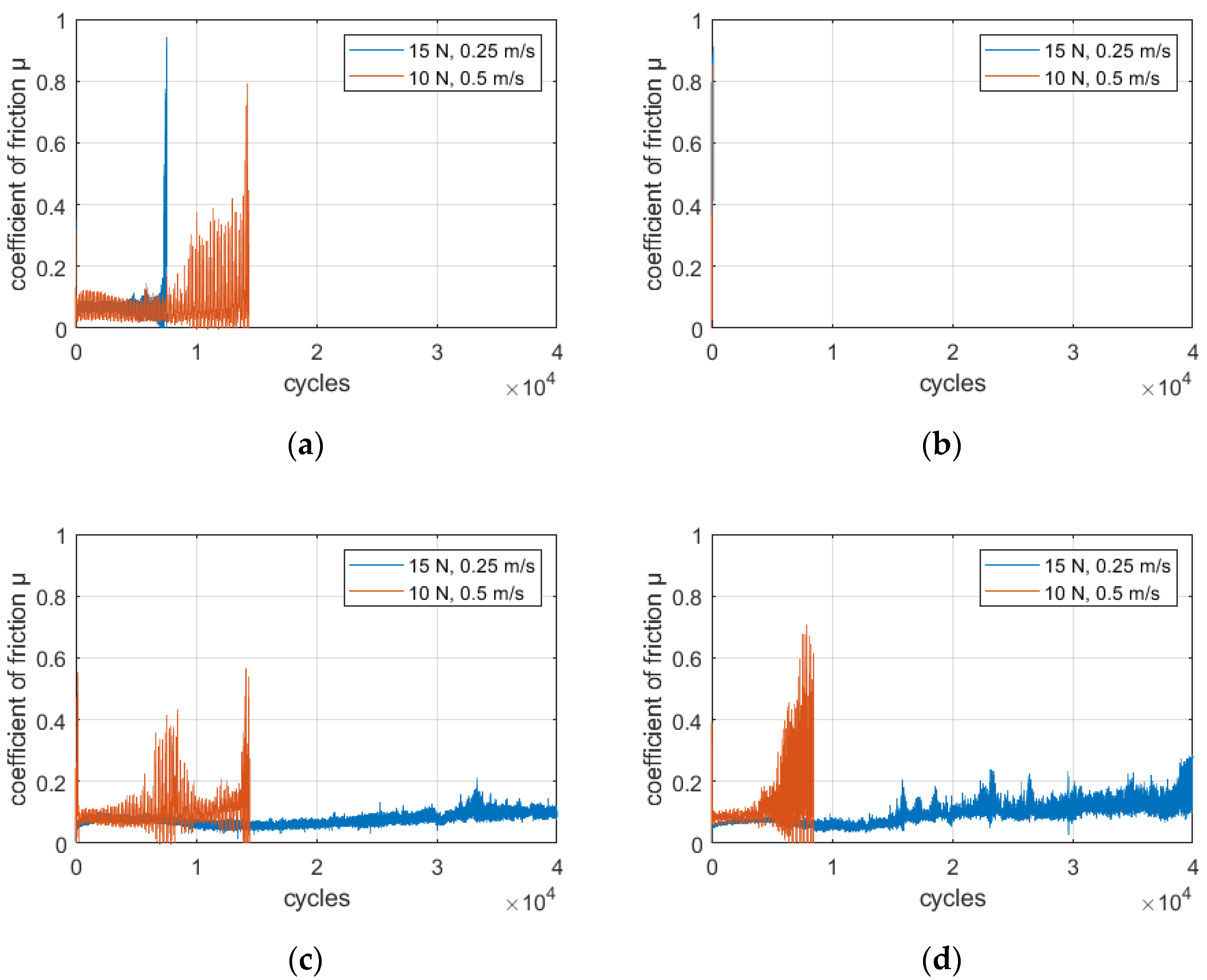
The coefficient of friction was continuously recorded at a data rate of 10 Hz during the tests. The resulting friction curves were plotted over the cycles and are shown for the ‘S’ nitriding variants in
Figure 6a–d.
Variant S1 exceeded the limit coefficient of friction of 0.5 at relatively low cycle counts of 7600 and 14,500 after a short period of instability. Nitriding variant S2 failed in the pin-on-disc tests immediately after the start, possibly due to spalling of the compound layer under the mechanical load. In contrast, the specimen S3 showed a significantly different behavior with changed testing normal force. While the friction coefficient became unstable early and exceeded 0.5 at only 14,500 cycles with a normal force of 10 N and a sliding speed of 0.5 N, the sample withstood the complete 40,000 cycles at 15 N and a sliding speed of 0.25 m/s. The same behavior was observed for variant S4 but combined with a slightly more unstable evolution of the friction coefficient and an even earlier point of failure at 8500 cycles for a normal force of 10 N.
The friction curves for the D nitriding variants are shown in
Figure 7a–d. D1 and D2 reached high runtimes for all testing conditions while maintaining low friction forces. Run-throughs were achieved with D1 at 10 N and with D2 at 15 N. Slight instabilities of the coefficient of friction can be seen, especially for variant D2. D3 and D4, on the other hand, failed at early stages below 20,000 cycles.
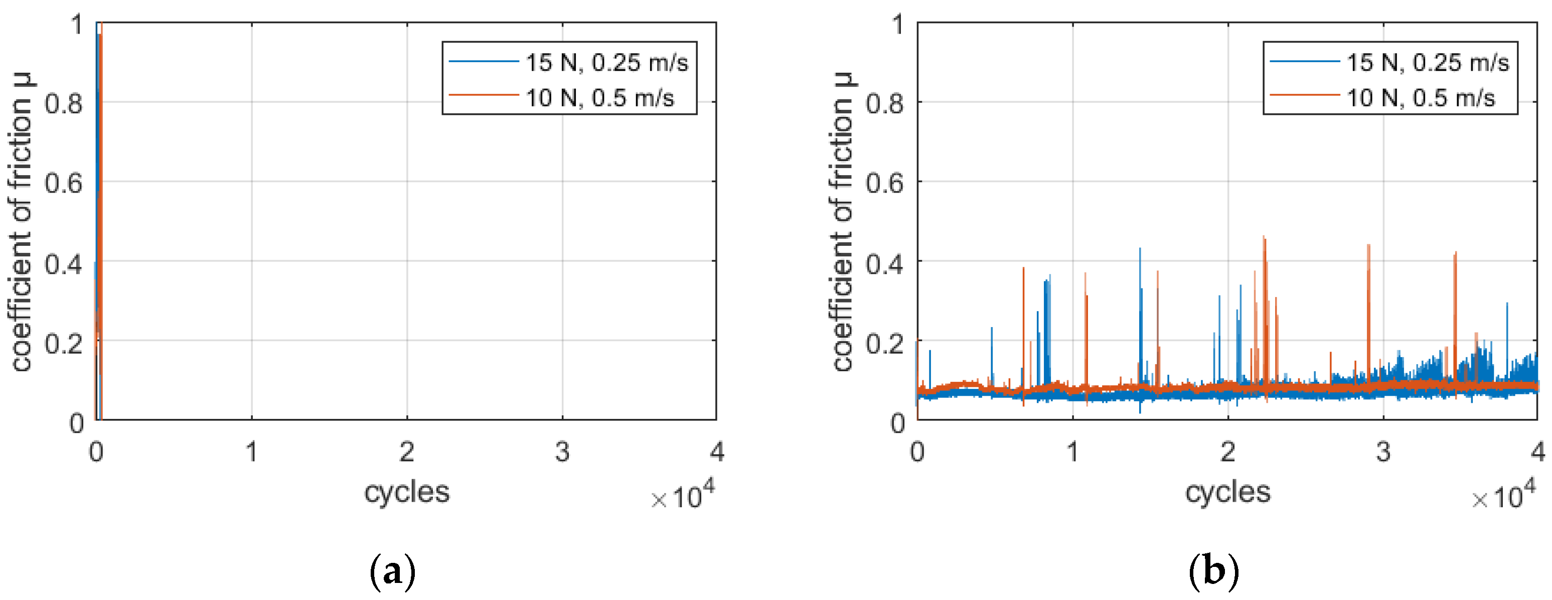
For comparison, the coefficients of friction for the reference variants are shown in
Figure 8. The uncoated sample in the nitrided state D2 failed after only a few hundred cycles in the pin-on-disc tests. The two-layer coating system of TiCN + MoS
2:Ti, on the other hand, ran under both test conditions for the maximum of 40,000 cycles. The friction coefficient was at a low level with some peaks up to 0.4 but immediately returned to below 0.1 after a few seconds. This behavior may be caused by a temporal loss of the lubrication film on the counterbody or by the formation and discharge of hard particles such as titanium or molybdenum carbides. Towards the end of the test, from approx. 28,000 cycles, a slight increase of the coefficient of friction can be observed at a normal force of 15 N and a sliding speed of 0.25 m/s.
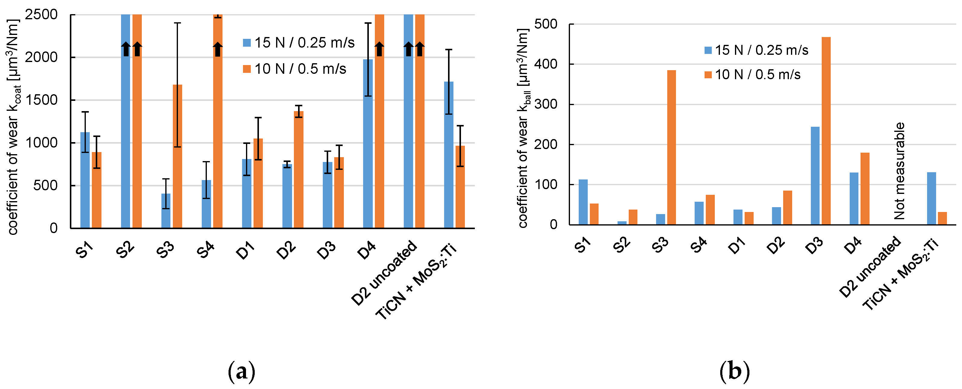
3.5. Coefficient of Wear
The coefficients of wear determined from the resulting cross-sections of the wear tracks on the duplex-treated specimens are shown in
Figure 9a. While the wear coefficients of the duplex-treated surface layers (with the exception of the S2 variant) ranged between 400 and 2000 µm
3/Nm for the testing condition 15 N/0.25 m/s, the coefficient of wear of the nitrided-only sample was two to three orders of magnitude higher, at approx. 353,000 µm
3/Nm. The two-layer coating system TiCN +MoS
2:Ti deposited on a polished specimen without a supporting nitrided layer had a wear coefficient of about 1700 µm
3/Nm which was in the upper range of wear coefficients after duplex treatment.
For the testing condition 10 N/0.5 m/s, the wear coefficient increased for almost all duplex variants compared with the higher loading. For the variants S4 and D4 that cannot be shown completely in the diagram, wear coefficients of about 4000 µm3/Nm and 4600 µm3/Nm, respectively, were calculated.
The wear rates of the EN100Cr6 counterbodies are shown in
Figure 9b. Noticeable are the S3, D3, and D4 variants where significant wear was detected, especially for the tests with 10 N and 0.5 m/s. For S3 and D4, already high wear coefficients were observed on the duplex system side under these conditions. On the pin that was paired with the uncoated nitrided reference sample, no evaluable wear mark was generated due to the short duration of the test. The counterbody wear rate of the pin paired with the TiCN + MoS
2:Ti layer system was in range with the duplex variants S1, S2, S4, D1, and D2.
Figure 10 shows an example of some of the wear tracks after the pin-on-disc tests at 15 N and 0.25 m/s. The first two examples show the impact of the coating. The uncoated compound layer with a thickness of about 13 µm, which was produced with the two-stage nitriding treatment D2, exhibits a deep, rough wear track after the wear test. Coating with the MoS
2:Ti solid lubricant significantly changes the appearance of the wear track. The depth of the wear mark is significantly less and is in the range of the thickness of the coating. The duplex-treated variant D2 belongs to the surface systems with the best performance.
The other two examples in
Figure 10c,d show the wear tracks of the coated specimen with the nitrided condition D1 (which achieved a long runtime in the pin-on-disc test) and the coated sample with the nitrided condition S2 (which had failed after only a few cycles). The wear track of sample D1 in
Figure 10c appears similar to that of the duplex-treated sample D2 in
Figure 10b, which had a similar compound layer thickness but a slightly lower porosity. The S2 variant, which failed shortly after the start of the pin-on-disc test, had a compound layer of only about 7 µm thickness. The wear track of this specimen looks very rugged. It seems that fragments of the compound layer have broken out.
4. Discussion
All nitriding variants showed a good MoS
2:Ti layer adhesion after the PVD coating step, and compared well with the reference coating system with a TiCN interlayer. This might be caused by mechanical interlocking of the solid lubricant to the porous compound layers [
21,
22]. With regard to the wear behavior, the coating systems with the Ti-doped MoS
2 top layer significantly improved the wear behavior compared to the nitrided-only surfaces.
Overall, the investigated variants performed better at higher normal force (which corresponds to a higher initial surface pressure). The reduced wear was found on the coated side as well as on the ball wear side. In the investigated duplex system of compound layer and solid lubricant coating, the lower friction at higher forces could be due to the MoS2:Ti solid lubricant being more strongly pressed into the pores and irregularities on the surface, thus improving the lubricating effect.
The compound layer thickness seemed to have an influence on the wear behavior of the duplex-treated surface layers. The duplex systems with the nitrided states S1 and S2 with thin compound layer thicknesses of only 6–7 µm failed early in the pin-on-disc tests. This is in a good agreement with observations made on purely nitrided surface layers in [
1] and [
14], on the basis of which a minimum compound layer thickness of 10 µm is recommended for nitrided components subject to wear.
In the literature, with regard to the phase composition of the compound layer, the highest possible contents of ε-nitride are recommended for high wear resistance of nitrided components [
14]. The compound layers studied in this work had similar phase compositions with predominantly γ’-nitride, with the exception of the variant D4. In the latter, nitrocarburizing was applied in the second process step to promote the formation of the ε-phase by additional diffusion of carbon. In terms of thickness and pore content of the compound layer, the variant D4 can be compared to variant D3. The variant D4 achieved a similar sliding distance as the variant D3 in the pin-on-disc test at 10 N and 0.5 m/s, but D4 exhibited a significantly higher coefficient of wear after the test. Under the test conditions of 15 N and 0.25 m/s, the variant D4 achieved about twice the number of cycles as D3, but again higher wear was observed on the variant D4 after the test. Under the test conditions, a high proportion of the ε-nitride phase appeared to be unfavorable for the wear behavior of the duplex system. In studies on the tribological load-carrying capacity of compound layers on the material EN31CrMoV9, it was also observed that a high proportion of ε-nitride led to unfavorable wear behavior [
1]. An unfavorable residual stress state within the multiphase compound layer was suspected as the cause. This could also be a reason for the poorer wear behavior in the case of the duplex system.
As seen from the metallographic cross-sections, the compound layers under investigation had different porosities. A correlation between porosity and coating adhesion or wear behavior in the pin-on-disc test could not be demonstrated in the present investigations. The pores also varied in size and distribution. The pores formed during the nitriding process were very small compared with other surface inhomogeneities resulting from manufacturing and the formation of nitrides. Therefore, quantitative determination of the porosity by simple surface roughness Sa measurements was not possible. In order to prove correlations between the wear behavior of the duplex systems and the porosity, more precise methods for characterizing the porosity (i.e., SEM recordings of the surface) must be applied.
The pore seam of purely nitrided parts has different effects on their tribology: On the one hand, increased initial wear often occurs in the area of the pore zone. Crack formation and breaking out of larger solid particles, which remain as wear debris in the tribosystem can promote more abrasive wear and is favored by coarsely formed pores. On the other hand, open porosity can serve as a lubricant reservoir and frequently has a positive effect on wear behavior, especially under conditions of insufficient lubrication. In the case of duplex treatment, the pores in the compound layer are covered by the coating. However, the surface texture caused by the pores could still have a positive effect on the coating; this is because the mechanical interlocking and thus the adhesive strength is improved, and the solid lubricant layer can be rubbed into the pores and thus remains available for longer, as shown for surface structuring in [
20].
In the case of the duplex system investigated, the nitrided layer had a different significance with regard to the supporting effect because no hard layer (instead a comparatively soft layer (approx. 700 HV)) was applied by the PVD process. The nitrided case was kept constant for all nitriding variants at approx. 0.8 mm to rule out any influence of the mechanical supporting zone depth. Nevertheless, there were differences in the hardness of the diffusion zone due to varying nitriding parameters which were necessary to produce different compound layers.
The hardness of the nitrided layers was determined by Vickers indentation (HV0.5). In order to eliminate the influence of the embedding material, the first reliable hardness imprint could be made only at a distance of 50 µm from the surface, which is already beneath the compound layers. In that region the nitrided zones exhibit a similar hardness like the MoS
2:Ti solid lubricant coating. The hardness of the compound layers could not be determined by HV0.5 testing. It is known from the literature that it is approx. 1200 HV for the investigated material EN31CrMoV9 in the compact compound layer and decreases in the area of the pores [
14,
28]. Nevertheless, a direct correlation between the hardness of the nitrided layers and the wear behavior could not be demonstrated in the present investigations.
The investigations give first evidence for an expected good wear behavior of MoS2:Ti PVD-coated compound layers. In order to further identify the influences of the compound layer structure on the wear mechanisms, additional investigations such as ultra-microhardness tests on the compound layers and FIB cuts are needed to estimate whether the solid lubricant is forced into the open pores. Scratch tests can also provide further insight into the duplex system.

 ,
, 


