Article

On the Direct Extrusion of Solder Wire from 52In-48Sn Alloy

Department of Metal Forming, South Ural State University, Lenin Prospect 76, 454080 Chelyabinsk, Russia
*
Author to whom correspondence should be addressed.
Machines 2021, 9(5), 93; https://doi.org/10.3390/machines9050093
Submission received: 14 April 2021 / Revised: 27 April 2021 / Accepted: 29 April 2021 / Published: 6 May 2021
(This article belongs to the Special Issue Selected Papers from the ICIEAM 2021 Conference)

Abstract

:
In this article, technology for producing wire and rod solder from 52In-48Sn alloy has been developed and investigated in the conditions of small-scale production. The use of direct extrusion of wire and rods instead of traditional technology for producing solder, which includes pressing, rolling and drawing, can significantly reduce the fleet of required equipment. Using only a melting furnace and a hydraulic press, solder wires and rods can be produced in various sizes. Shortening the production cycle allows you to quickly fulfill small orders and be competitive in sales. This article develops a mathematical model of direct extrusion, which allows you to calculate the extrusion ratio, extrusion speed and pressing force. The results of modeling the process of extrusion of wire Ø2.00 mm and rods Ø8.0 mm made of 52In-48Sn alloy are presented. The temperature of the solder and the tool is simulated in software QForm based on the finite element method. Experimental results of manufacturing Ø2.0 mm solder wire and Ø8.0 mm rods are presented. The microstructure of the direct extruded solder is a eutectic of phases γ and β. Energy-dispersive X-ray spectroscopy (EDS) mapping of the 52In-48Sn alloy showed that the solder obtained by direct extrusion has a uniform distribution of structural phases. The developed technology can be used in the manufacture of wires and rods from other low-melting alloys.

1. Introduction

Solder is a material that is used to join metals by soldering. It always has a melting point lower than the parts to be joined [1]. To date, a large number of solder alloys have been created, which differ in composition, material ratio, and the presence of impurities [2,3,4,5,6,7,8]. According to the melting temperature, the solders are subdivided into solders for low-temperature soldering with a melting point of no more than 450 °C [9] and soldering alloys for high-temperature soldering with a melting point of more than 450 °C [10]. According to the main component, solders are subdivided into: gallium; indium; bismuth; tin-lead; pewter; cadmium; lead; zinc; aluminum; germanium, etc. Tin (Sn)—lead (Pb) low-melting alloy is the most common type of solder [11]. SnPb-solders are made in the form of round wire, tape, triangular, round and square rods, round tubes filled with flux, and powder.
Tin (Sn)-based lead (Pb)-free solders have been introduced because of the health and environmental concerns about conventional Pb-Sn solders. In 2006, the European Union’s RoHS (Restriction of the Use of Certain Hazardous Substances) Directive on the Environment restricted the use of lead in new electrical and electronic equipment to a maximum of 0.01% [12]. Several environmentally friendly Sn-based alloys such as Sn-3.0Ag-0.5Cu [13], Sn-14Bi-5In [14], Sn-0.7Cu [15], Sn-9Zn [8], Sn-8Zn-3Bi [16], Sn-58Bi [17], Sn-52.5Bi-2.68In-1Ga [5], and Sn-In [6] have been considered the most promising candidates to replace the toxic Sn-Pb alloy from electronic packaging systems [2].
As of 2016, In-48Sn alloy solder is one of the most commonly used in semiconductor technology. While being Pb free, the eutectic SnIn solder offers very low melting points and bonds well to copper, nickel, and gold substrates [18]. The eutectic point shown in the phase diagram [6] is at 118 °C with the composition of 51.7 at. % In and 48.3 at. % Sn (Figure 1). The equilibrium phases are terminal In and Sn solid solutions, two intermediate phases β and γ, and the eutectic between the last two phases [6,19]. The microstructure of the alloy with the chemical composition In-49Sn is shown in Figure 2 [20]. Eutectic SnIn (52In-48Sn by weight) has often been used as a specialty solder in applications where a low melting point alloy is required, such as in step soldering or when the components in an assembly are sensitive to temperature [21].
Physical and mechanical properties of the 52In-48Sn alloy are presented in Table 1 [22].
52In-48Sn is considered the lowest melting point practical solder. It is often used as the last step in a sequential soldering operation, and for soldering to metallizations on temperature-sensitive components. 52In-48Sn is relatively ductile. Elongation is reported to be 83%. This higher elongation is a result of superplastic behavior in creep under shear loading at a temperature above 0.8 of their melting temperature (Tm) [23].
The traditional technology for the production of solders (Figure 3) [24] consists of the following stages: alloy preparation, casting of ingots (100–200 mm in diameter), extruding, and drawing to the required diameter. In some cases, billet rolling can be applied between extruding and drawing (Figure 4) [25].
Traditional technology for the production of solder wire requires not only a large fleet of equipment but also often comes with problems related to the stability of the drawing process. Frequent breaks of the wire during rolling and especially during drawing [26,27,28,29] require the improvement of technology and its production. At the same time, there are known methods of making wire by extrusion [30,31,32], which are used in medicine. We have not found any publications describing small-scale technology for the manufacture of wire solder.
The purpose of this work is to develop and study a technology for the manufacture of wire and rod from 52In-48Sn lead-free alloy in the conditions of small-scale production.

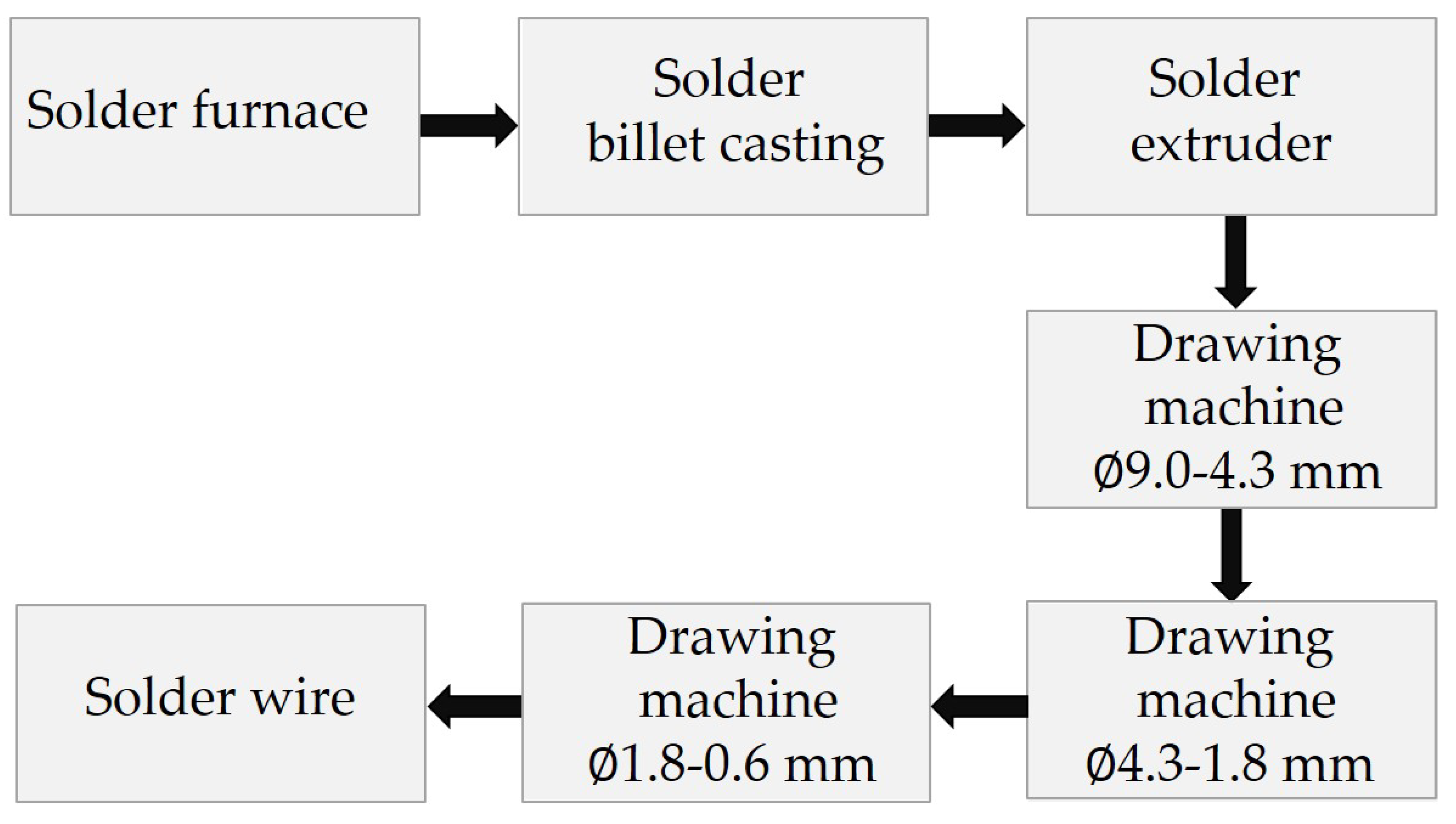
2. Materials and Methods

The study of the technology for the manufacture of wire and rod solder was carried out in the laboratories of the South Ural State University, Chelyabinsk, Russia.
The alloy was melted in a SmartMelt 2.0 crucible furnace. The heating temperature was 300 to ensure the dissolution of pure (99.999%) indium (In) and pure (99.915%) tin (Sn). The chemical composition of the obtained alloy was checked by an inductively coupled plasma atomic emission spectrometer (ISP-MS) NETZCH Optima 2100 DV (PerkinElmer, Waltham, MA, USA). The chemical composition of the sample’s structural components was analyzed on a JSM-6460LV scanning electron microscope (EDS) (JEOL, Tokyo, Japan) equipped with an energy dispersive spectrometer (OxfordInstruments, Abingdon, United Kingdom) for qualitative and quantitative X-ray microanalysis. The results of the average value in a threefold analysis of the chemical composition of the alloy are presented in Table 2. Billets with a diameter of 30 and 20 mm were obtained by casting molten alloy into metal molds (Figure 5).
For extrusion, we used a hydraulic press, which is equipped with a system for registering the pressing force and the speed of the traverse (Figure 6). The maximum press power is 617 kN. The traverse speed of the press is from 0.5 to 12 mm/s. A photo and drawing of the tool for obtaining wire and rods, developed by us, are shown in Figure 7. The tool shown in Figure 7 was made in two versions: the diameter of the container is 32 mm and 21.8 mm. For the manufacture of wire and rods, dies of diameters were used: 2.0 and 8.0 mm. The extrusion was carried out without the use of a lubricant and using graphite as a lubricant. To determine the temperature of the wire and rods at the exit from the die, a DT-9860 pyrometer and an RY-107 thermal imager was used.
The specialized software QForm (QuantorForm LLC, Russia) was used to simulate the extrusion process.
The microstructure of the samples was studied on an Axio Observer D1.m optical inverted metallographic microscope (Carl Zeiss Microscopy GmbH, Jena, Germany) equipped with ThixometPro software (Thixomet Pro, Thixomet Company, Saint Petersburg, Russia). Tensile tests were carried out on an INSTRON 5882 universal testing machine (Norwood, MA, USA).

3. Results and Discussion

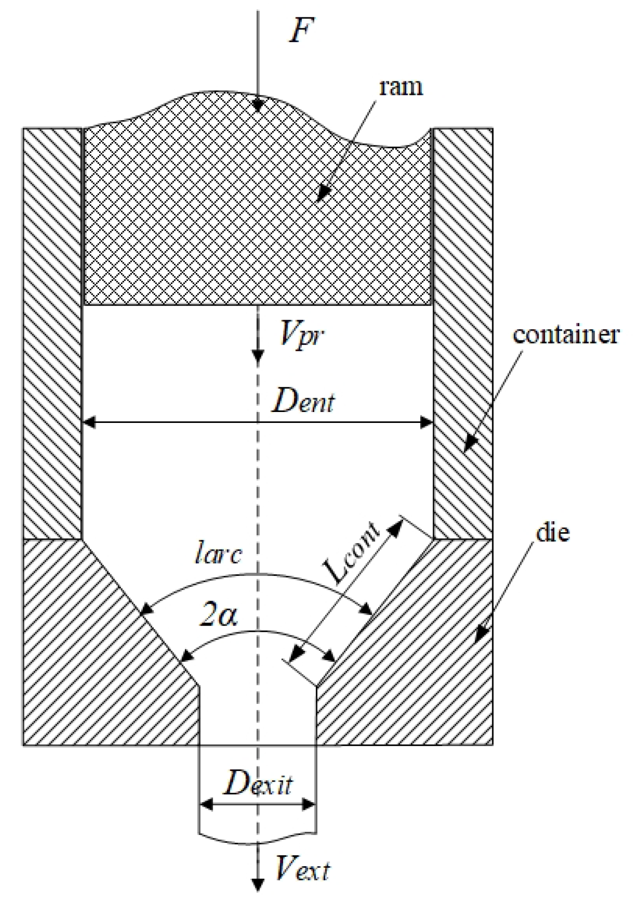
3.1. Mathematical Modeling for the Extrusion Process

To calculate the parameters of the extrusion process, we compiled a mathematical model [33].
The energy for pressing is supplied to the extrusion ram by force F, while the total work of process A is the sum of the plastic deformation work A d e f and the friction forces work A f r .
A = A d e f + A f r
Figure 8 shows a diagram of the deformation zone during pressing. The extrusion energy consumption (while neglecting the sliding friction forces on the contact surface of the ram and the container) is proposed to be estimated as a sum of forces:
F = F d e f + F f r
where F d e f —forming (plastic deformation) force and F f r —efforts to overcome sliding friction forces on the processed metal with the container and the die contact surface. The derivation of the equation for determining the plastic deformation required force can be based on the Fink dependence. This dependence determines the work of metal shaping, spent on the implementation of plastic deformations, determined by the initial and final dimensions of the processed metal (without taking into account the peculiarities of the plastic deformation conditions):
A F = θ · σ a v · l n μ
where θ —volume of processed metal;   μ —extrusion ratio
μ = D e n t 2 D e x i t 2
D e n t = D c o n —billet diameter at the entrance to the die equal to the container diameter; D e x i t —diameter of the wire (rod) at the exit from the die; σ a v —average value of the processed metal deformation resistance, which can be determined as (5), under the assumption that the specific resistivity of the billet metal deformation is equal to the average value of the yield stress
σ a v = σ · σ e x i t
where σ—billet material yield strength and σ e x i t —metal yield stress at the exit from the die.
A distinctive feature of the considered extrusion process is the value of the deformation zone shape parameter Δ B = l a r c / L c o n t = <<1, where l a r c is the length of the arc perpendicular to the tool contact line in the middle of the deformation zone and L c o n t is the length of the tool contact line (Figure 1).
The value Δ B is calculated by the equation:
Δ B = α μ 1 μ · ( 1 + 1 μ 1 μ ) 2 ,  
where α—half-angle of the die.
The shape parameter Δ B << 1 leads to an increase in power conditions similarly to how it is accepted in sheet rolling. It should be taken into account when calculating:
A d e f = 1 Δ B · A F = 1 Δ B · θ · σ a v · l n μ .
Taking into account that the deformation power on one side is
N d e f = F d e f · V p r
where V p r —pressing speed (movement speed of the ram)—can on the other hand be found as
N d e f = d A d e f d t = 1 Δ B · σ a v · l n μ · d θ d t = 1 Δ B · σ a v · l n μ · S e n t · V p r
Provided that the area of the round billet is
S e n t = π · D e n t 2 4
The equation for calculating the deformation force is:
F d e f = π · D e n t 2 4 · 1 Δ B ·   σ a v · l n μ .
The friction force F f r is determined by the geometry of the deformation zone (Figure 1) and consists of three components: the effort aimed at overcoming the processed metal sliding friction against the container F f r I , the surface of the die F f r I I , and the parallel land of the die F f r I I I [15]
F f r = F f r I + F f r I I + F f r I I I .
The formation of friction forces according to Sybel’s law is
τ = f · σ
Components of friction forces can be found:
F f r I = S c o n · τ = π · D c o n · L b i l · f · σ
F f r I I = S d i e · τ = π 4 · sin α · ( D c o n 2 D e x i t 2 ) · f · σ τ
F f r I I I = S c a l · τ = π · D e x i t · L c a l · f · σ e x i t ,  
where f—friction coefficient; S c o n , S d i e , S c a l —lateral surface area of the container inner liner, die and its parallel land; D c o n —container diameter; σ τ —plastic shear strength
σ τ = σ a v 2 = σ · σ e x i t 2
L b i l —length of pressed billet; and L c a l —length of die parallel land.
The mathematical model of direct extrusion is implemented in the Excel mathematical table. An example of calculating the power conditions for pressing rods Ø2.00 and 8.00 mm from the Sn-In alloy are given in Table 3.
The developed mathematical model was used to analyze the influence of changes in the friction coefficient in the container on the pressing force (Figure 9). With a friction coefficient in the container of 0.4, the pressing force at the initial moment and at its completion is 40 kN. Additionally, with a friction coefficient of 0.1, the difference between the forces does not exceed 10 kN. Therefore, from the point of view of reducing energy consumption for the pressing process and increasing its efficiency, the use of technological lubricants is very useful.

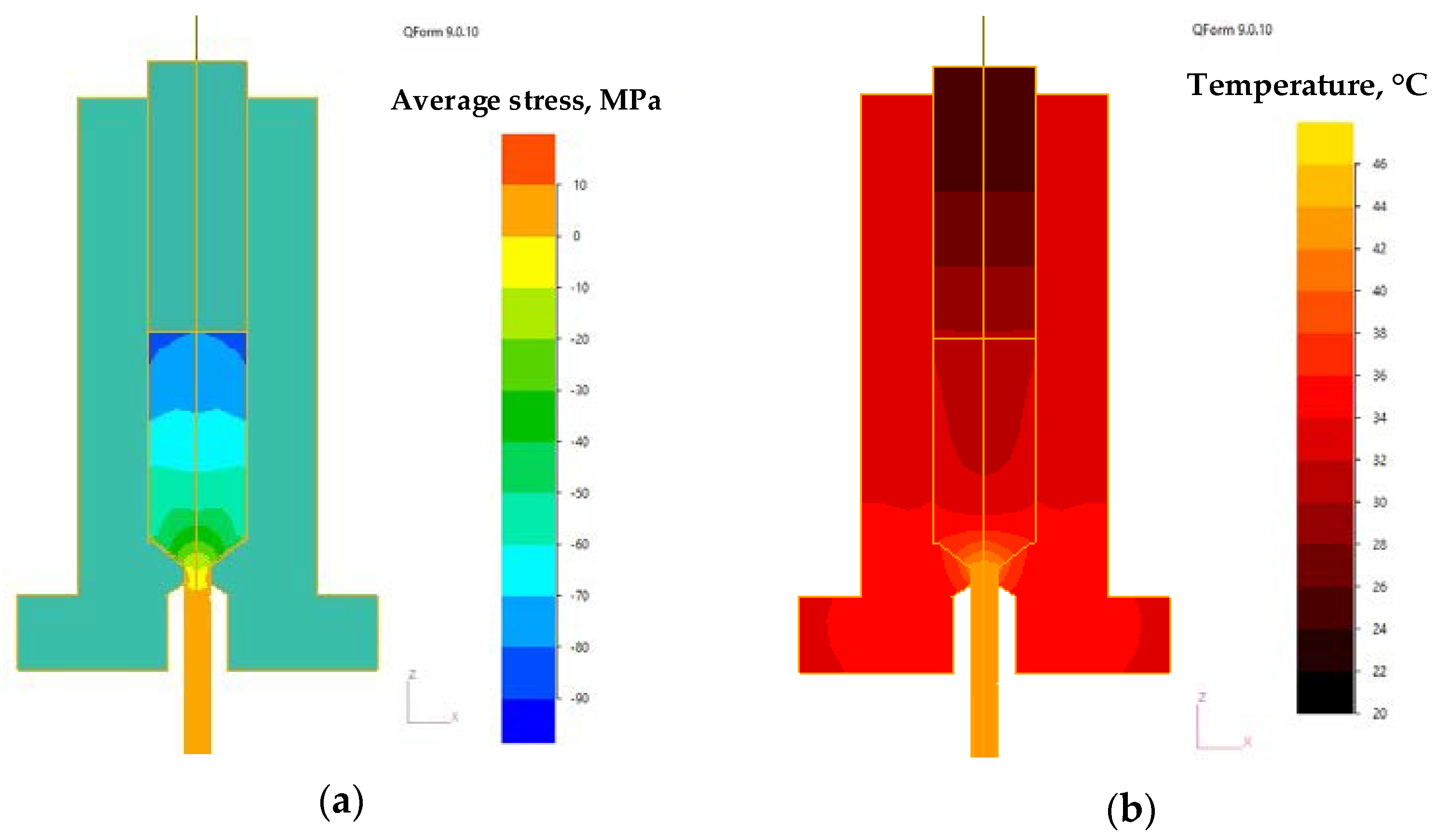
3.2. Extrusion Temperature Simulation in QForm Software

To simulate the stress-strain state and temperature in metal-forming processes, it is convenient to use software such as DEFORM (developed by Scientific Forming Technologies Corporation, Columbus, Ohio, USA) [34], Simulia Abaqus (Dassault Systemes, Velizy-Villacuble, France) [35], and QForm2D/3D (QuantorForm LLC, Moscow, Russia) [36]. However, it must be said that temperature modeling of low-melting materials in the direct extrusion process has not been revealed in the literature.
To simulate the extrusion process, 2D and 3D models of the tool and billet were created. In the process of simulation, it is possible to determine not only the stress-strain state but also the temperatures of the metal and the tool (Figure 10). The characteristics of the material were as follows: resistance to deformation σ = 10.5 MPa, density ρ = 7300 kg/m3, thermal conductivity λ = 86 W/m K, and heat capacity C = 230 J/kg K. To graphically display the temperature change in the billet, 9 points were selected in each of the billet (Figure 11). Three points in the center of the workpiece, three on the edge and three in between. During the simulation, temperature changes were investigated during the extrusion Ø2.0 mm wire and Ø8.0 mm rod at different speeds.
In Figure 12a,c,e graphs of temperature measurements at the points under study during the extrusion of wire Ø2.0 mm with pressing speeds of 0.5 are provided; 1.0 and 3 mm/s. The extrusion speed was 59.4 mm/s, 118.8 mm/s and 356.4 mm/s, respectively. As can be seen in the graphs (Figure 12a,c,e) the metal pressing speed significantly affects the temperature of the metal in the die. The maximum heating temperature of the metal corresponds to points 2, 4 and 5. At point 5, the temperature with an increase in the pressing speed from 0.5 to 3.0 mm/s increases from 33.4 to 75.8 °C. The heating of the metal is caused by deformation processes. Heating due to friction of the metal on the surface of the container is insignificant and does not exceed 2–3 °C, which is characterized by the temperature at points 6 and 9.
In Figure 12b,d,f, graphs of temperature measurement at the points under study are provided when pressing a rod Ø8.0 mm with pressing speeds of 0.5, 1.0 and 3 mm/s. The extrusion speed was 2.15 mm/s, 4.3 mm/s, and 12.9 mm/s, respectively. As can be seen in the graphs (Figure 12b,d,f), the temperature of the metal in this case does not exceed 30 °C. The maximum heating is only 10 °C. The extrusion speed in this case does not exceed 13 mm/s. Small deformations cause slight heating of the metal. Analyzing the flow of metal when pressing the bar, you can see that point 3 has the highest temperature. The reason for the greatest heating of the metal precisely at point 3 is, most likely, in addition to deformation heating, the friction of the metal at the billet–container contact. When extruding rods of 8.0 mm, it is possible to increase the pressing speed and, as a consequence, the productivity of the process.
Simulation of a single extrusion process has shown that the temperature of the metal in the deformation zone at high pressing speeds increases quite significantly. In small-scale production, 30–50 billets are continuously extruded. With continuous extrusion, heating the alloy will lead to heating of the tooling, the accumulation of heat by it and an even greater increase in the temperature of the alloy in the deformation zone. The study of this effect on the temperature of the die was carried out using axisymmetric modeling of pressing the wire at a speed of 3 mm/s, considering the heat exchange of the tool with the environment and the billet. The graph of the die temperature change based on the results of the simulation of four cycles of extrusion of the billet into a wire of Ø2 mm at a pressing speed of 3 mm/s are shown in Figure 13a. During extrusion, the die heats up at the point of contact to a temperature of 60–80 °C. At the same time, according to the results of the simulation of multiple extrusion, we can speak of the average die temperature at the level of 50 °C. The temperature of the container during extrusion also gradually increases (Figure 13b). The maximum temperature of the container during the extrusion of four billets rises by 10 °C. The average container temperature rises by 4 °C.

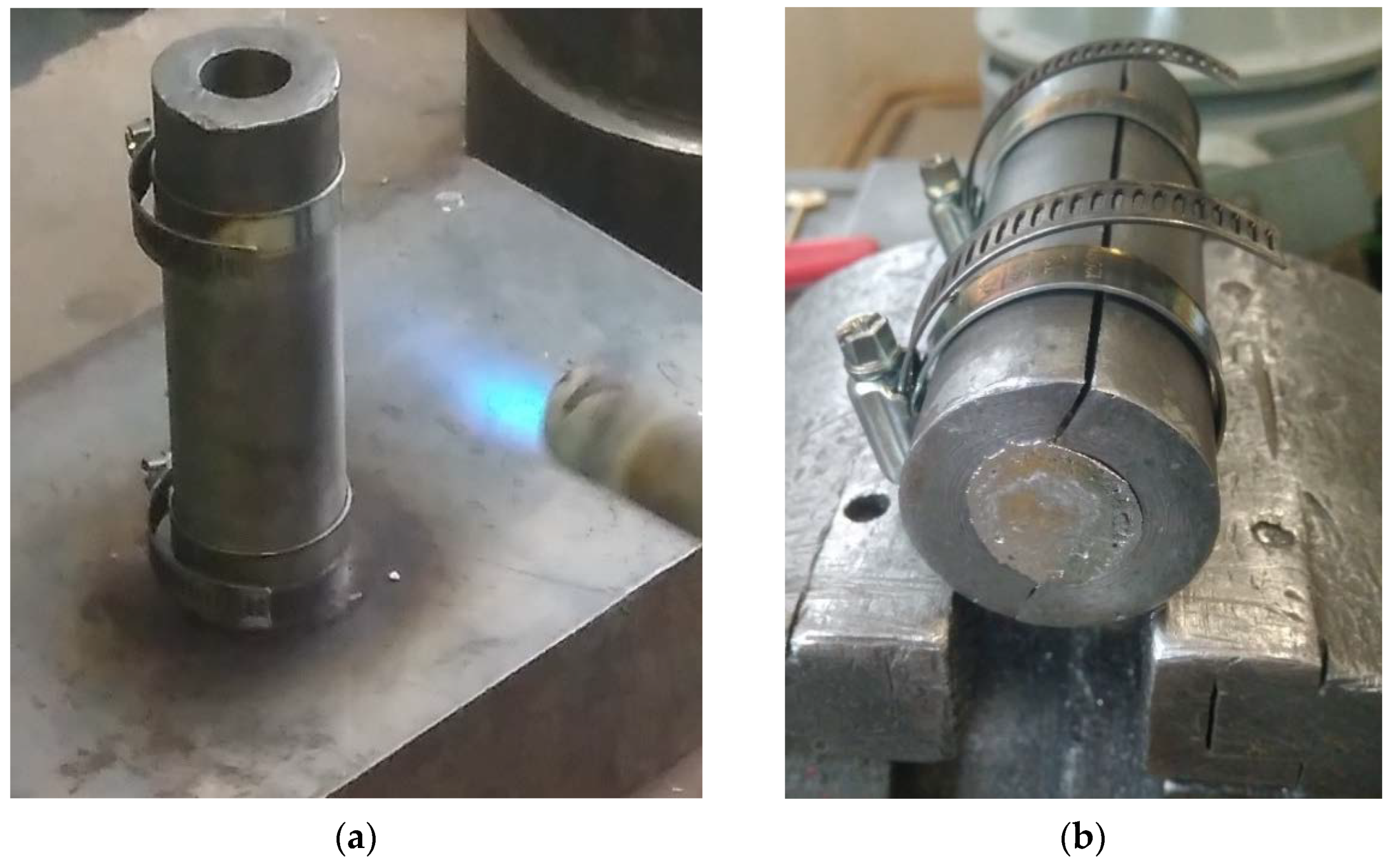
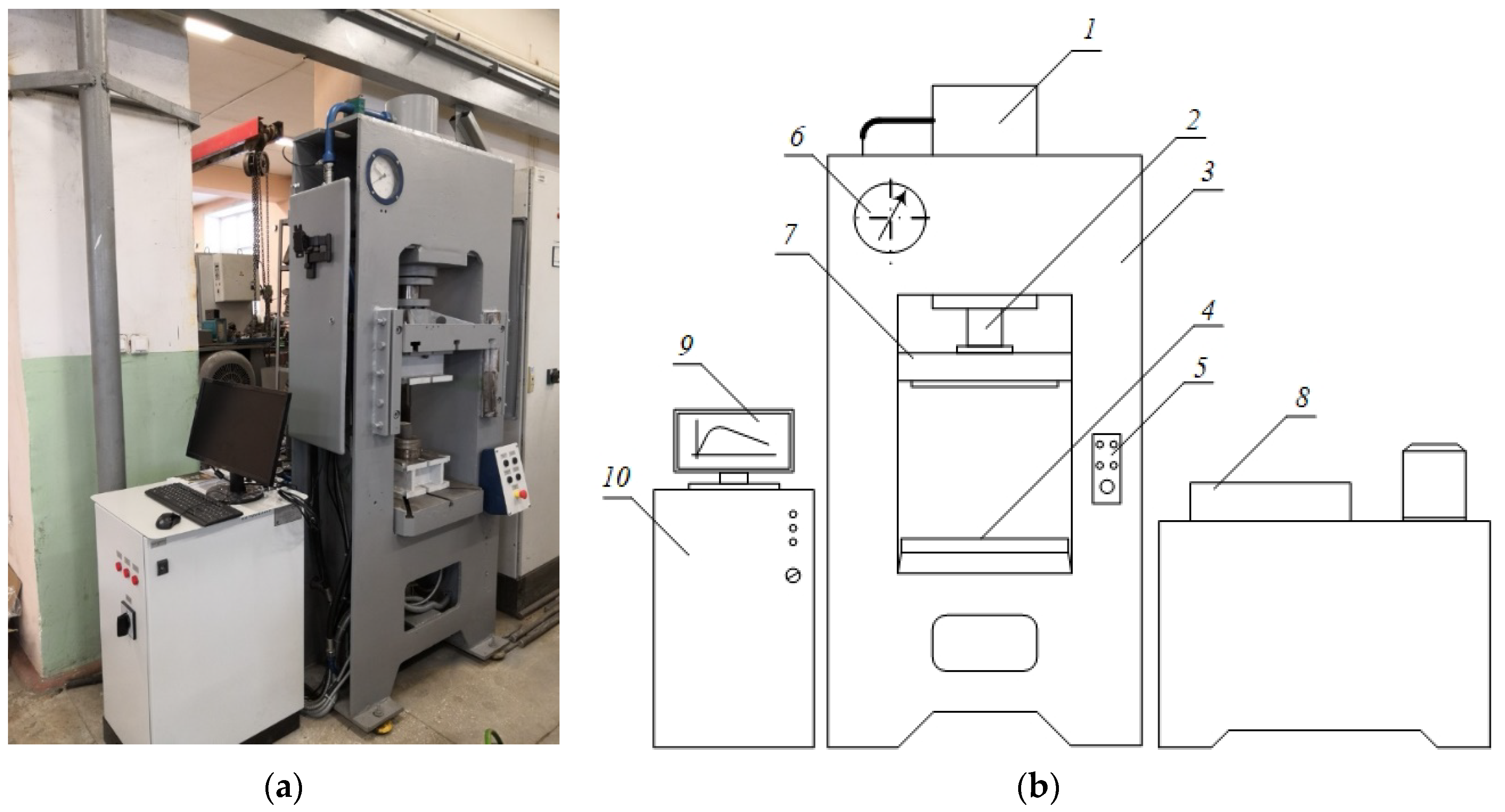
3.3. Experimental Studies of Wire and Rods Extrusion

Rods were obtained from cast sections during the experiment in accordance with the conditions presented in Table 2. Extrusion was carried out without lubrication and using graphite lubricant. The forces during pressing were recorded by the system (Figure 14). The calculated forces according to Table 1 at the start of pressing should be 106 kN with a friction coefficient of 0.5. In the experiment, the pressing force was 116 kN. The deviation of 10% may be due to the coefficient of friction. We assumed that it is 0.5, but in reality, it can be slightly higher. Force measurements have shown that the use of a lubricant can reduce the force at the start of pressing from 116 to 56 kN. According to Figure 9b, the friction coefficient when using graphite lubricant is 0.05. The use of lubricant during pressing can significantly reduce the energy consumption to overcome friction. It is logical to assume that a decrease in friction at the contact of the container-alloy will lead to a decrease in the temperature of the solder rod. Measurement of the temperature of the solder rod at the exit from the die, made by a pyrometer, showed that this is exactly the case. The use of graphite lubricant allows us to reduce the temperature of the bar at the exit from the die from 30 to 22 °C (Table 4). The room temperature during the experiment was 20 °C. With a sequential process of pressing several billets, this difference will increase, according to the calculated vlues given in Figure 12 and Figure 13.
Solder wire and rods obtained by direct extruding are shown in Figure 15. Tensile tests have shown that the resulting wire and rods have a tensile strength of 11 MPa. The values obtained by us are consistent with the data given in Table 1.
The microstructures of the extruded 52In-48Sn alloy are shown in Figure 16. The microstructure is a eutectic of phases γ and β. Energy-dispersive X-ray spectroscopy (EDS) mapping of the 52In-48Sn alloy showed (Figure 17) that γ—solid solution of In in Sn and β—solid solution of Sn in In. The solder obtained by direct extrusion has a uniform distribution of structural phases.
Wire and rod can be obtained in various standard sizes of 52In-48Sn alloy direct extrusion. The transition from one standard size to another does not require significant time and material costs. Additionally, the developed technology can be used in the manufacture of wires and rods from other low-melting alloys. In continuation of the work already done, it is planned to improve the tool and technology for obtaining rosin core solder wire.

4. Conclusions

In this article, a technology for producing wire and rod solder from 52In-48Sn alloy has been developed and investigated in the conditions of small-scale production. The use of direct extrusion of wire and rods instead of the traditional technology for producing solder, which includes pressing, rolling and drawing, can significantly reduce the fleet of required equipment. Using only a melting furnace and a hydraulic press, solder wires and rods can be produced in various sizes. Shortening the production cycle allows you to quickly fulfill small orders and be competitive in sales.
Studies of the developed technology of direct extrusion have shown:
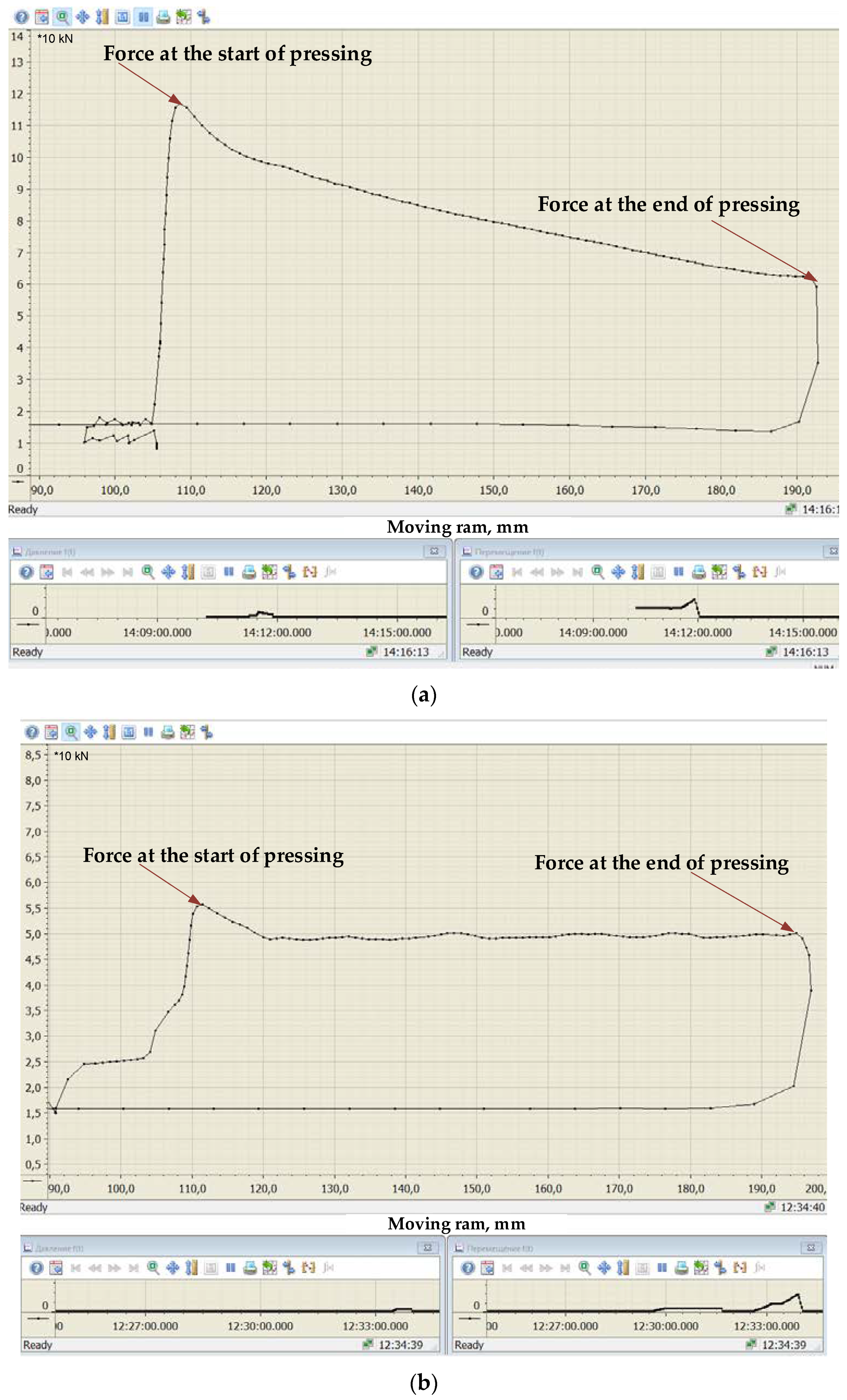
  • A mathematical model of direct extrusion has been developed, which allows us to calculate extrusion ratio, extrusion speed and pressing force. The discrepancy between the calculated and experimental results does not exceed 10%.
  • In mathematical modeling, it was found that a decrease in the friction coefficient from 0.4 to 0.1 reduces the force at the start of pressing from 97 to 71 kN when extruding a 2.0 mm wire and from 94 to 54 kN when extruding a rod of Ø8.0 mm.
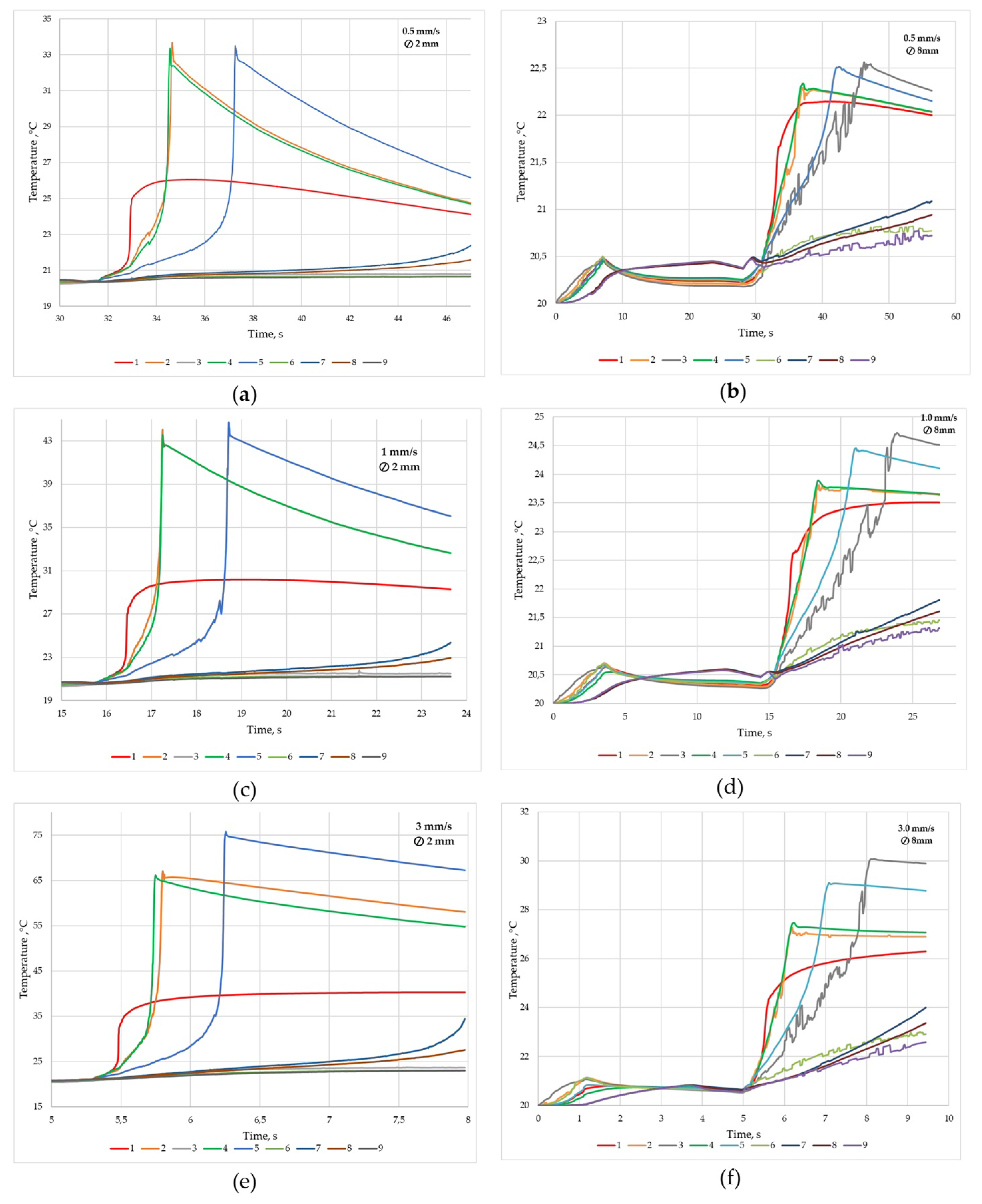
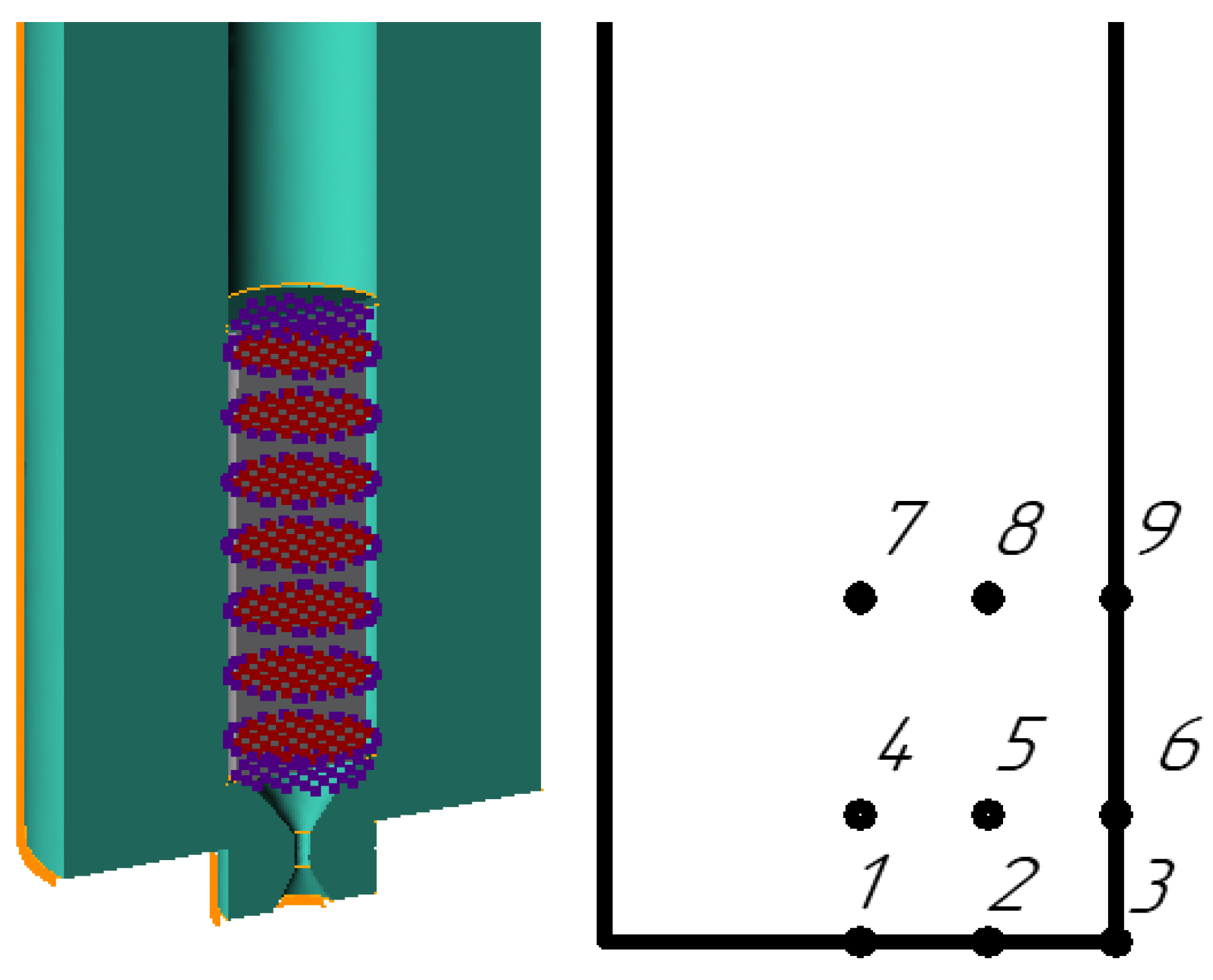
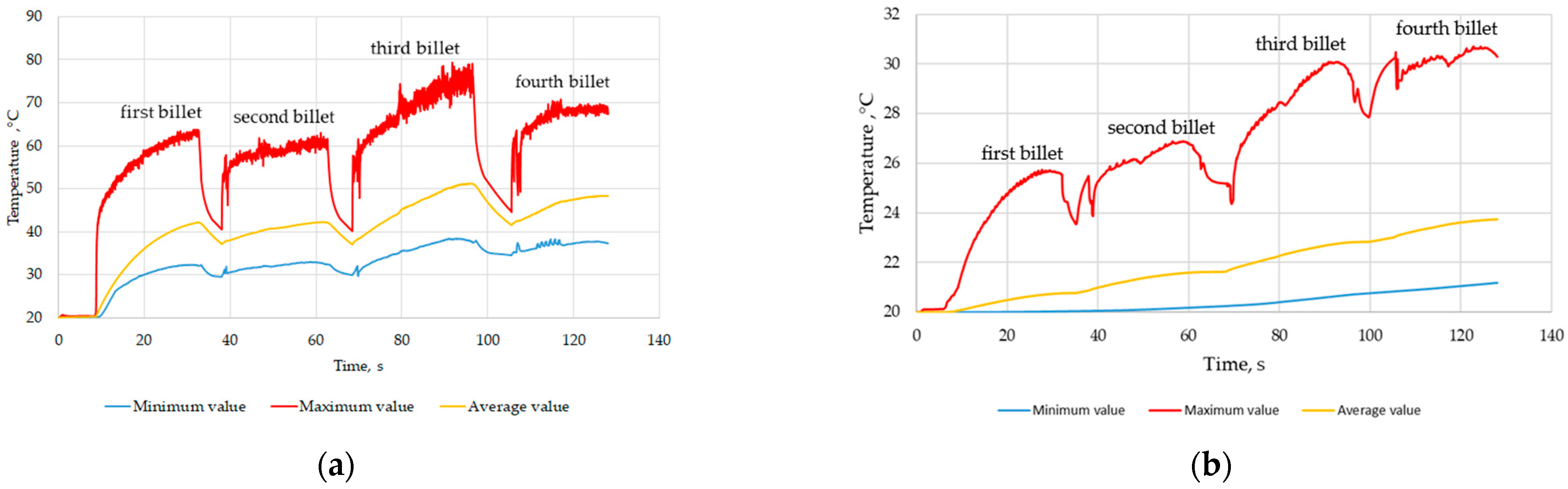
  • The temperature of the solder and the tool the extrusion process is determined by simulation in software QForm, based on the finite element method. With an increase in the pressing speed from 0.5 to 3 mm/s, the maximum temperature of the Ø2 mm solder increases by 2.2 times and 1.3 times when pressing a rod Ø8.0 mm. The temperature with an increase in the pressing speed from 0.5 to 3.0 mm/s increases from 33.4 to 75.8 °C for 2.0 mm wire and from 22.5 to 30 °C for Ø8.0 mm rod. With successive pressing of four billets, the maximum temperature of Ø2.0 mm wire of solder increases to 79 °C, and the maximum temperature of the container increases by 10 °C.
  • An experimental study has established that the use of graphite lubricant makes it possible to reduce the friction coefficient from 0.5 to 0.05, which reduces the temperature of the solder at the die exit from 30 to 22 °C when manufacturing a rod Ø8.0 mm at a pressing speed of 3 mm/s.
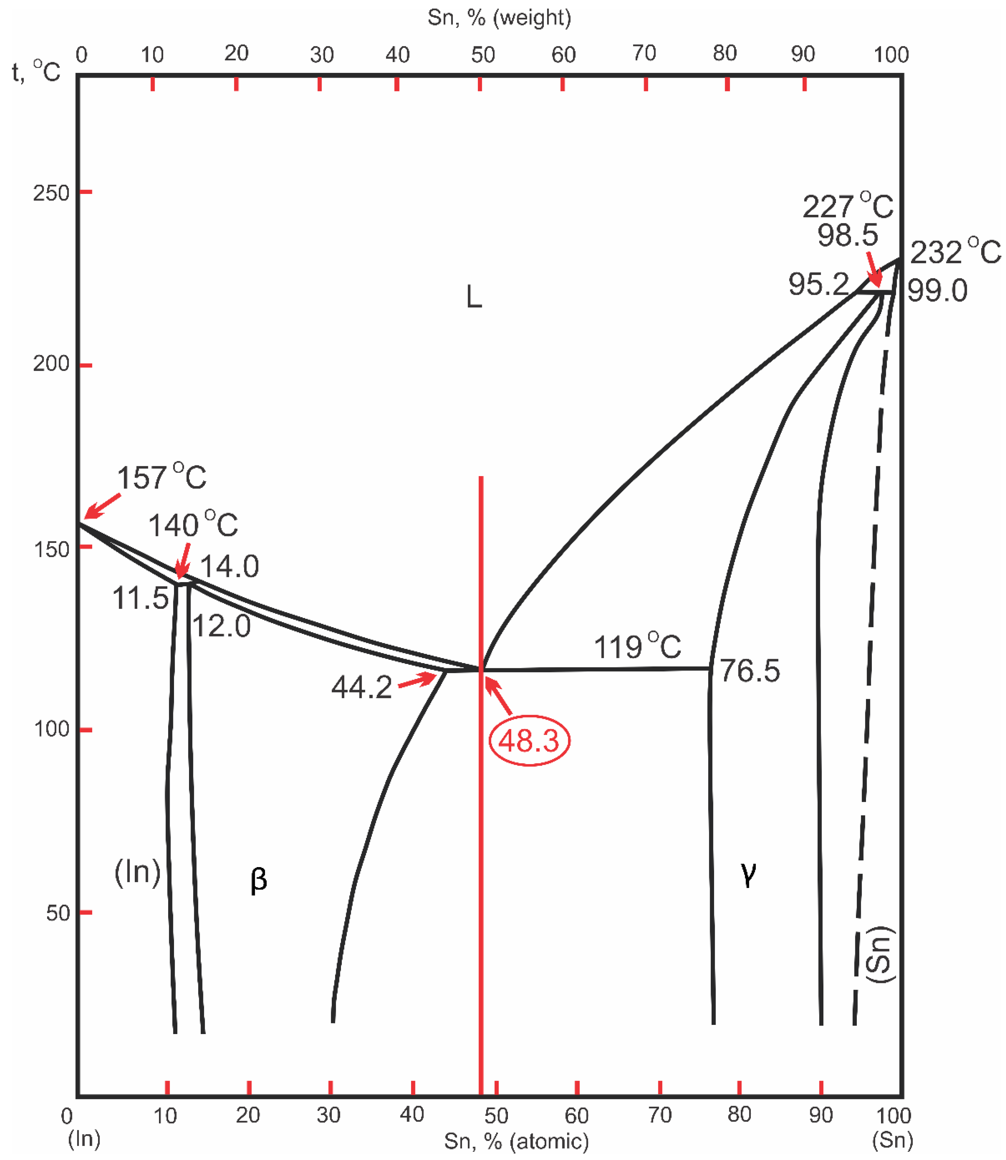
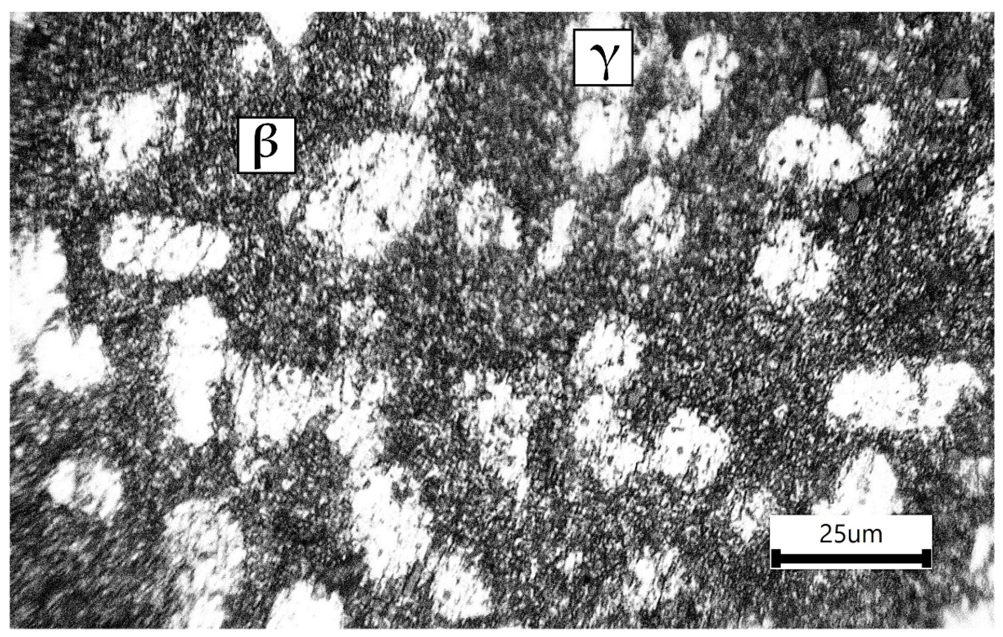
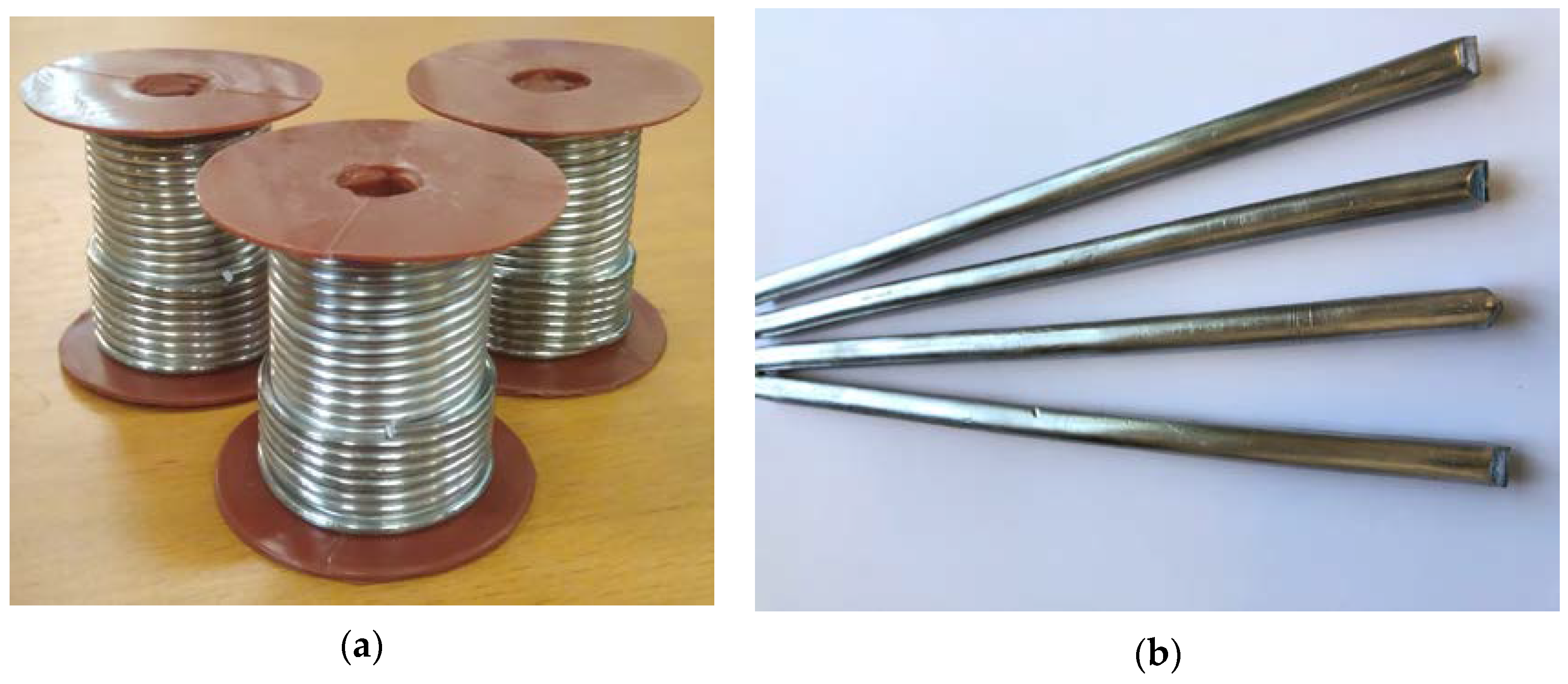
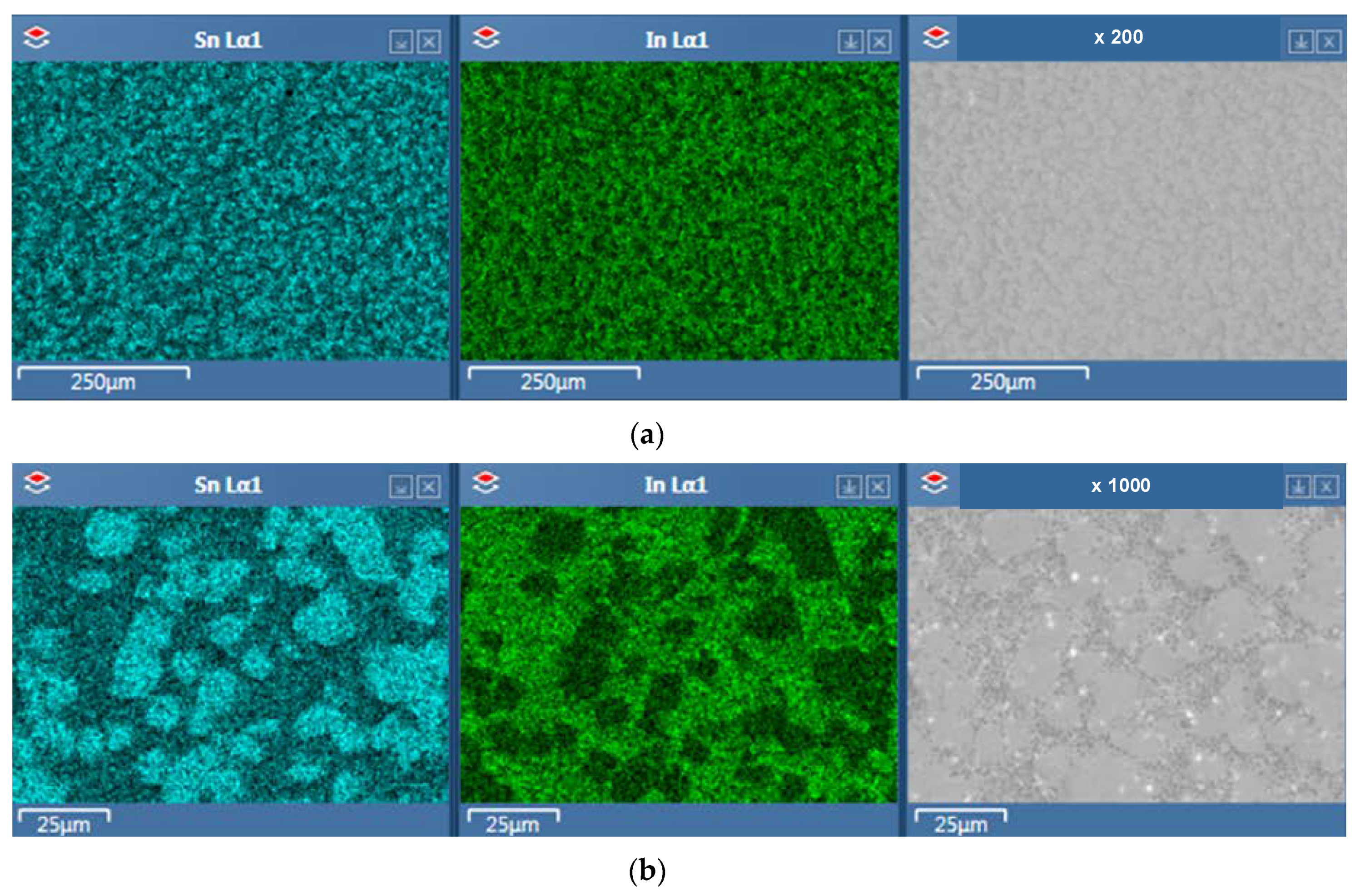
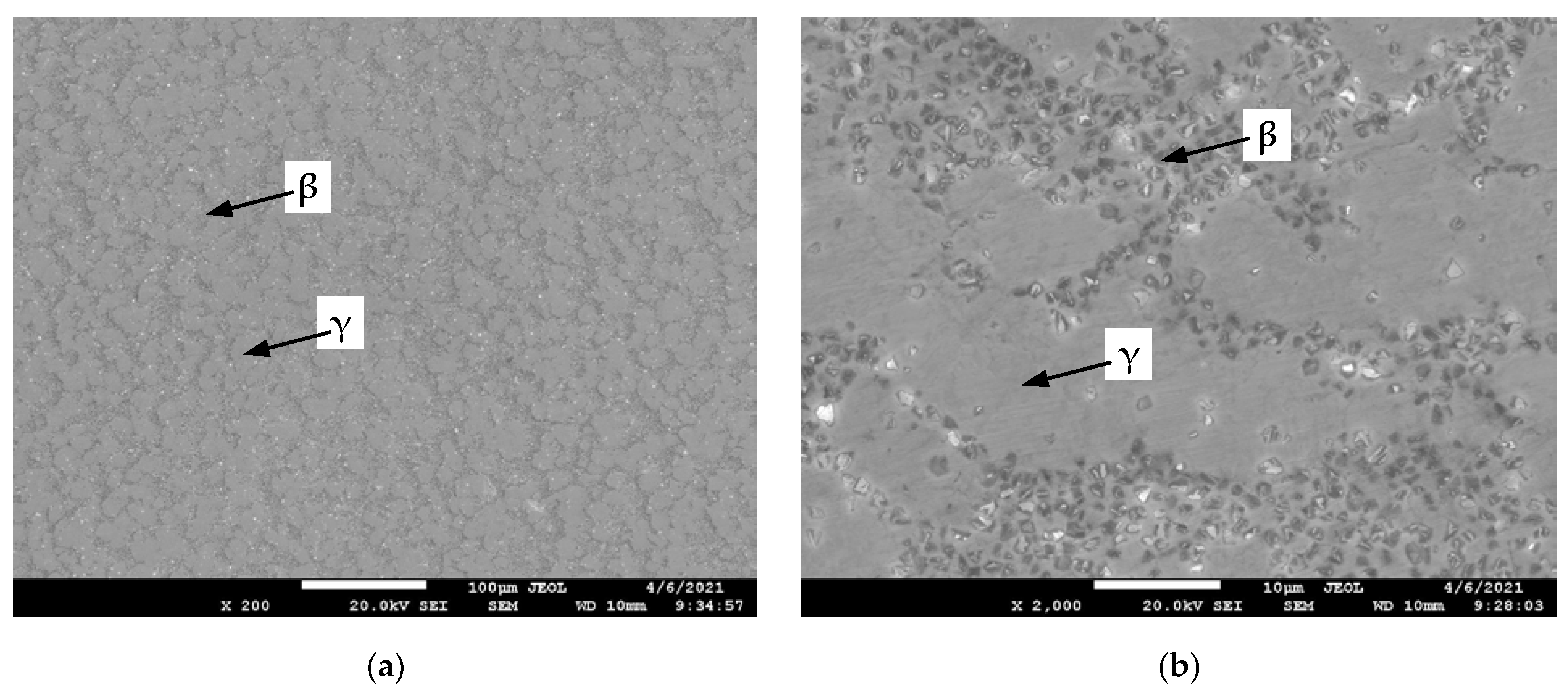
  • Visual and microstructural analysis of the rod and wire showed their compliance with the customer’s requirements. The microstructure is a eutectic of phases γ and β. Energy-dispersive X-ray spectroscopy (EDS) mapping of the 52In-48Sn alloy showed that the solder obtained by direct extrusion has a uniform distribution of structural phases.
  • The developed technology can be used in the manufacture of wires and rods from other low-melting alloys. In continuation of the work already done, it is planned to improve the tools and technology for obtaining rosin core solder wire.

Author Contributions

Conceptualization, S.F. and L.R.; methodology, A.S. (Aleksandr Sarafanov); software, D.G.; validation, I.E.; data curation, L.G. and V.B.; conducted the metallographic analysis, A.S. (Alexandra Svistun) and A.B.; writing—original draft preparation, L.R.; writing—review and editing, L.R. All authors have read and agreed to the published version of the manuscript.

Funding

This research received no external funding.

Institutional Review Board Statement

Not applicable.

Informed Consent Statement

Not applicable.

Data Availability Statement

The data presented in this study are available on request from the corresponding author.

Conflicts of Interest

The authors declare no conflict of interest.

References

  1. Arabian, J. Computer Integrated Electronics Manufacturing and Testing, 1st ed.; Marcel Dekker, Inc.: New York, NY, USA, 1989. [Google Scholar] [CrossRef]
  2. Abtew, M.; Selvaduray, G. Lead-free solders in microelectronics. Mater. Sci. Eng. R Rep. 2000, 27, 95–141. [Google Scholar] [CrossRef]
  3. Raeder, C.; Felton, L.; Tanzi, V.; Knorr, D. The effect of aging on microstructure, room temperature deformation, and fracture of Sn-Bi/Cu solder joints. J. Electron. Mater. 1994, 23, 611–617. [Google Scholar] [CrossRef]
  4. Sommadossi, S.; Fernández Guillermet, A. Interface reaction systematics in the Cu/In–48Sn/Cu system bonded by diffusion soldering. Intermetallics 2007, 15, 912–917. [Google Scholar] [CrossRef]
  5. Yang, C.-H.; Zhou, S.; Lin, S.-K.; Nishikawa, H. A Computational Thermodynamics-Assisted Development of Sn-Bi-In-Ga Quaternary Alloys as Low-Temperature Pb-Free Solders. Materials 2019, 12, 631. [Google Scholar] [CrossRef] [Green Version]
  6. Liu, Y.; Tu, K.N. Low melting point solders based on Sn, Bi, and in elements. Mater. Today Adv. 2020, 8, 100115. [Google Scholar] [CrossRef]
  7. Chriašteľová, J.; Ožvold, M. Properties of solders with low melting point. J. Alloys Compd. 2008, 457, 323–328. [Google Scholar] [CrossRef]
  8. Kotadia, H.R.; Howes, P.D.; Mannan, S.H. A review: On the development of low melting temperature Pb-free solders. Microelectron. Reliab. 2014, 54, 1253–1273. [Google Scholar] [CrossRef]
  9. Kang, H.; Rajendran, S.H.; Jung, J.P. Low Melting Temperature Sn-Bi Solder: Effect of Alloying and Nanoparticle Addition on the Microstructural, Thermal, Interfacial Bonding, and Mechanical Characteristics. Metals 2021, 11, 364. [Google Scholar] [CrossRef]
  10. Efimochkin, Y.I.; Fedotov, S.V.; Rylnikov, V.S.; Afanasev-Khodykin, A.N. High-temperature brazing alloys produced by mechanical alloying. Weld. Int. 2016, 30, 229–231. [Google Scholar] [CrossRef]
  11. Rahman, M.M.; Ahmed, S.R.; Kaiser, M.S. On the investigation of reuse potential of SnPb-solder affected copper subjected to work-hardening and thermal ageing. Mater. Charact. 2021, 172, 110878. [Google Scholar] [CrossRef]
  12. EU. Directive 2002/95/EC of the European parliament and of the council of 27 January 2003 on the restriction of the use of certain hazardous substances in electrical and electronic equipment. Off. J. Eur. Union 2003, 13, 19–22. [Google Scholar]
  13. Gain, A.K.; Zhang, L.; Chan, Y. Microstructure, elastic modulus and shear strength of alumina (Al2O3) nanoparticles-doped tin–silver–copper (Sn–Ag–Cu) solders on copper (Cu) and gold/nickel (Au/Ni)-plated Cu substrates. J. Mater. Sci. Mater. Electron. 2015, 26, 7039–7048. [Google Scholar] [CrossRef]
  14. Gnecco, F.; Ricci, E.; Amore, S.; Giuranno, D.; Borzone, G.; Zanicchi, G.; Novakovic, R. Wetting behaviour and reactivity of lead free Au–In–Sn and Bi–In–Sn alloys on copper substrates. Int. J. Adhes. Adhes. 2007, 27, 409–416. [Google Scholar] [CrossRef]
  15. Gain, A.K.; Zhang, L.; Quadir, M.Z. Thermal aging effects on microstructures and mechanical properties of an environmentally friendly eutectic tin-copper solder alloy. Mater. Des. 2016, 110, 275–283. [Google Scholar] [CrossRef]
  16. Gain, A.K.; Zhang, L. Microstructure, thermal analysis and damping properties of Ag and Ni nano-particles doped Sn–8Zn–3Bi solder on OSP–Cu substrate. J. Alloys Compd. 2014, 617, 779–786. [Google Scholar] [CrossRef]
  17. Gain, A.K.; Zhang, L. Growth mechanism of intermetallic compound and mechanical properties of nickel (Ni) nanoparticle doped low melting temperature tin–bismuth (Sn–Bi) solder. J. Mater. Sci. Mater. Electron. 2016, 27, 781–794. [Google Scholar] [CrossRef]
  18. Morris, J.W.; Goldstein, J.L.F.; Mei, Z. Microstructure and mechanical properties of Sn-In and Sn-Bi solders. JOM 1993, 45, 25–27. [Google Scholar] [CrossRef]
  19. Okamoto, H. Binary Alloy Phase Diagrams; ASM International: Materials Park, OH, USA, 1990; Volume 3, pp. 2295–2296. [Google Scholar]
  20. Chuang, T.H.; Yu, C.L.; Chang, S.Y.; Wang, S.S. Phase identification and growth kinetics of the intermetallic compounds formed during in-49Sn/Cu soldering reactions. J. Electron. Mater. 2002, 31, 640–645. [Google Scholar] [CrossRef]
  21. Freer, J.L.; Morris, J.W. Microstructure and creep of eutectic indium/tin on copper and nickel substrates. J. Electron. Mater. 1992, 21, 647–652. [Google Scholar] [CrossRef]
  22. Requirements for Electronic Grade Solder Alloys and Fluxed and Non-Fluxed Solid Solders for Electronic Soldering Applications STANDARD by Association Connecting Electronics Industries, 01/01/2006. Available online: https://www.techstreet.com/J-STD-006B|Solder|Alloy.J-STD-006B|Solder|Alloy (accessed on 10 January 2021).
  23. Lee, N. Getting Ready for Lead-free Solders. Solder. Surf. Mt. Technol. 1997, 9, 65–69. [Google Scholar] [CrossRef]
  24. Available online: https://dgvictory.en.alibaba.com/ (accessed on 10 January 2021).
  25. Available online: https://vicmachine.en.ecplaza.net/ (accessed on 10 January 2021).
  26. Švejcar, J.; Juliš, M.; Klakurková, L.; Gejdoš, P.; Zikmund, T. Analysis of Causes of Defects Appearance in Wire Drawing. Defect Diffus. Forum 2020, 405, 217–222. [Google Scholar] [CrossRef]
  27. Sun, L.; Bai, J.; Xue, F.; Chu, C.; Meng, J. The work softening behavior of pure Mg wire during cold Drawing. Materials 2018, 11, 602. [Google Scholar] [CrossRef] [Green Version]
  28. Radionov, A.A.; Radionova, L.V. Energy approach to the influence of countertension on drawing. Steel Transl. 2008, 38, 358–361. [Google Scholar] [CrossRef]
  29. Radionova, L.V.; Shirokov, V.V.; Faizov, S.R.; Zhludov, M.A. Studies of Influence of Process Parameters on the Strain Rate at High-Speed Wire Drawing. Mater. Sci. Forum 2019, 946, 832–838. [Google Scholar] [CrossRef]
  30. Nienaber, M.; Yi, S.; Kainer, K.U.; Letzig, D.; Bohlen, J. On the Direct Extrusion of Magnesium Wires from Mg-Al-Zn Series Alloys. Metals 2020, 10, 1208. [Google Scholar] [CrossRef]
  31. Jäger, A.; Habr, S.; Tesař, K. Twinning-detwinning assisted reversible plasticity in thin magnesium wires prepared by one-step direct extrusion. Mater. Des. 2016, 110, 895–902. [Google Scholar] [CrossRef]
  32. Tesař, K.; Balík, K.; Sucharda, Z.; Jäger, A. Direct extrusion of thin Mg wires for biomedical applications. Trans. Nonferrous Met. Soc. China 2020, 30, 373–381. [Google Scholar] [CrossRef]
  33. Radionova, L.V.; Faizov, S.R.; Sarafanov, A.E. Mathematical Modelling of Low Temperature Solder Direct Extrusion. IOP Conf. Ser. Mater. Sci. Eng. 2020, 969, 012107. [Google Scholar] [CrossRef]
  34. Poláková, I.; Zemko, M.; Rund, M.; Džugan, J. Using DEFORM Software for Determination of Parameters for Two Fracture Criteria on DIN 34CrNiMo6. Metals 2020, 10, 445. [Google Scholar] [CrossRef] [Green Version]
  35. Belyakov, N.; Smirnova, O.; Alekseev, A.; Tan, H. Numerical Simulation of the Mechanical Behavior of Fiber-Reinforced Cement Composites Subjected Dynamic Loading. Appl. Sci. 2021, 11, 1112. [Google Scholar] [CrossRef]
  36. Biba, N.; Stebunov, S. QForm3D–cost effective simulation tool for metal forming technology. In Proceedings of the Korean Society for Technology of Plasticity Conference, 15th Forging Symposium, Changwon, Korea, 10–11 June 2010; pp. 77–80. [Google Scholar]
Figure 1. Sn-In binary phase diagram.
Machines 09 00093 g001
Figure 2. Microstructure of the eutectic In-49Sn solder.
Machines 09 00093 g002
Figure 3. Solder wire production line (type 1).
Machines 09 00093 g003
Figure 4. Solder wire production line (type 2).
Machines 09 00093 g004
Figure 5. Casting billets into molds: (a) mold; (b) billet in the mold.
Machines 09 00093 g005
Figure 6. Hydraulic press model D2428: (a) photo of laboratory hydraulic press; (b) scheme of laboratory hydraulic press: 1—main cylinder; 2—stroke; 3—housing; 4—bench; 5—control desk; 6—manometer; 7—slide; 8—oil pump; 9—monitor; 10—block of control and data collecting.
Machines 09 00093 g006
Figure 7. Extrusion tool: (a) photo tool; (b) tool drawing: 1—ram; 2—container; 3—die; 4—clamp; 5—saddle.
Machines 09 00093 g007
Figure 8. Scheme of the deformation zone during extrusion.
Machines 09 00093 g008
Figure 9. The results of modeling the pressing force with a change in friction in the container: (a) 2.0 mm; (b) Ø8.0 mm.
Machines 09 00093 g009
Figure 10. Simulation of the stress-strain state (a) and temperature (b) when extrusion occurred with a rod Ø8 mm in the QForm.
Machines 09 00093 g010
Figure 11. Location of temperature measuring points.
Machines 09 00093 g011
Figure 12. Extrusion process simulation results: (a) Ø2.0 mm, pressing speeds 0.5 mm/s; (b) Ø8.0 mm, pressing speeds 0.5 mm/s; (c) Ø2.0 mm, pressing speeds 1.0 mm/s; (d) Ø8.0 mm, pressing speeds 1.0 mm/s; (e) Ø2.0 mm, pressing speeds 3.0 mm/s; (f) Ø8.0 mm pressing speeds 3.0 mm/s.
Machines 09 00093 g012
Figure 13. Die (a) and container (b) temperature during extrusion wire ∅2.0 mm at 3 mm/s pressing speed.
Machines 09 00093 g013
Figure 14. Screenshots of the results of measuring the rod pressing force Ø8.00 mm (a) without lubrication and (b) with graphite grease.
Machines 09 00093 g014
Figure 15. 52In-48Sn alloy solder: (a) wire ∅2.0 mm; (b) rod ∅8 mm.
Machines 09 00093 g015
Figure 16. Microstructure of the 52In-48Sn alloy: (a) at 200× magnification; (b) at 2000× magnification.
Machines 09 00093 g016
Figure 17. Energy-dispersive X-ray spectroscopy (EDS) mapping of the 52In-48Sn alloy: (a) at 200× magnification; (b) at 1000× magnification.
Machines 09 00093 g017
Table 1. Physical and mechanical properties of the 52In-48Sn alloy.
Solidus/
Liquidus Temperature,°C
Alloy Density,
g/cm3
(at 22 °C)
Thermal Conductivity, W/mK
(at 85 °C)
Specific Electrical Resistance,
Ohmm
(at 22 °C)
Ultimate Tensile Strength, MPaElongation, %
(at 22 °C)
Brinell Hardness, HB
(at 22 °C)
117/1207.30860.14711.9835
Table 2. Chemical composition (wt.%) of the 52In-48Sn alloy.
MethodInSnImpurities
BiFeCuAsSb
ICP-MS51.00balance<0.015<0.01<0.01<0.006<0.015
EDS51.3648.64-----
Table 3. Results of mathematical model calculation.
ParameterUnitValue
Exper.1Exper.2
Initial data
Diameter   of   billet ,   D e n t mm2030
Diameter   of   the   wire   ( rod ) ,   D e x i t mm28
Billet length, Lmm120120
Container   diameter ,   D c o n mm21.832
Pressing   speed ,   V p r mm/s33
Billet material yield strength, σMPa10.510.5
Half-angle of the die, α°18.440
Length   of   die   parallel   land ,   L c a l mm55
Friction coefficient, f-0.50.5
Calculation results
Extrusion ratio, μ-118.816.0
Extrusion   speed ,   V e x t mm/s356.448
Force   at   the   start   of   pressing ,   F s t a r t kN105106
Force   at   the   end   of   pressing ,   F e n d kN71.955.6
Table 4. Experimental results rod extrusion.
ParameterDimensionValue
without Lubricationwith Graphite Lubricant
Diameter   of   the   rod ,   D e x i t mm88
Diameter   of   billet ,   D e n t mm3030
Pressing   speed ,   V p r mm/s33
Force   at   the   start   of   pressing ,   F s t a r t kN11656
Force   at   the   end   of   pressing ,   F e n d kN61.550
Solder   surface   temperature ,   T s °C3022
Publisher’s Note: MDPI stays neutral with regard to jurisdictional claims in published maps and institutional affiliations.

