Abstract
This paper discusses the author-developed novel method for the detection of buried metal objects that combines two basic subsurface sensing methods: one based on changes in the electromagnetic field parameters as induced by the inner or surficial impedance of the medium when affected by a propagating magnetic field; and one based on changes in the input impedance of the receiver as induced by the electromagnetic properties of the probed medium. The proposed method utilizes three instrumentation channels: two primary channels come from the ferrite magnetic antenna (the receiver), where the first channel is used to measure the current voltage amplitude of the active input signal component, while the second channel measures the current voltage amplitude of the reactive input signal component; an additional (secondary) channel comes from the emitting frame antenna (the transmitter) to measure the current amplitude of the exciting current. This data redundancy proves to significantly improve the reliability and accuracy of detecting buried metal objects. Implementation of the computational procedures for the proposed method helped to detect and identify buried objects by their specific electrical conductance and magnetic permeability, while also locating them depth-wise. The research team has designed an induction probe that contains two mutually orthogonal antennas (a frame transmitter and ferrite receiver); the authors herein propose a metal detector design that implements the proposed induction sensing method. Experimental research proved the developed combined method for searching for buried metal objects efficient and well-performing.
1. Introduction
Detection of buried metal objects (BO) has many important applications in the construction and operation of utility infrastructures, civil engineering, geological surveying, archeology, forensics, and geophysical logging, as well as treasure hunting and mine/weapon search [1,2,3,4,5,6]. For instance, public utility infrastructures are nowadays often laid underground, not only for esthetics or comfort of city/countryside dwellers, but also to protect said infrastructures against weather hazards and mechanical impacts [7]. Subsurface infrastructures include underground power lines, gas lines, telephone landlines, fiber-optic cables, TV cables, water pipelines, sewerage, etc. Engineering-related BOs also include a variety of metal components found inside the walls, between the flooring and the ceiling in high-rise buildings such as concrete reinforcement bars or various bearing structures. Apparently, some operations may damage BOs [8]. For instance, in any construction project that involves earthworks or drilling the walls, such objects might be damaged accidentally, which might have severe consequences. In such cases, workers have to avoid hitting such buried objects. In other cases, workers might actually want to hit a BO, e.g., when repairing a pipeline or a cable line, or making a tie-in, or drilling a hole that must go exactly through reinforcement bars inside a wall. Some may need to detect undesirable metals in foods [9,10,11]. Thus, accurate detection and localization of BOs is crucial.
Buried metal objects are searched for primarily by means of metal detectors [12,13,14,15,16,17,18].
2. Known Metal Detection Methods
Metal detectors are mainly based on generating a scanning alternating magnetic field and detecting its disruptions caused by metal objects. A metal detector contains two antennas, a transmitter and a receiver positioned in such way as to nullify the instrumentation signal if there are no BOs in the area. If there are any, they will disrupt this equilibrium that the receiver will respond to. Known metal detector designs are based on a variety of BO detection methods [15,18,19,20,21], with four being most prominent:
- BFO, or the beat frequency oscillation method that uses a single frame antenna. It measures how the electromagnetic properties of the probed medium affect the input impedance of the receiver that receives the re-emitted electromagnetic wave. The method essentially consists of reading the difference in the pulse frequency of signals coming from two generators, one of which generates a stabilized frequency, while the other one has a frame antenna in its frequency-setting circuit.
- OR, or the off resonance method that uses a single frame antenna. It measures how the electromagnetic properties of the probed medium affect the input impedance of the receiver that receives the re-emitted electromagnetic wave. The method is based on measuring the changes in the signal amplitude on the coil (the frame antenna) of a circuit whose resonance frequency is close to that of the signal that the reference generator feeds to the circuit.
- IB, or the induction balance method based on the reception−transmission principle: the frame receiver registers a signal re-emitted by a metal object (the target) when affected by an alternating magnetic field that is generated by the frame transmitter. This method is based on registering the response to the inner or surficial impedance of the medium as affected by the electromagnetic wave propagating in or above ground; the response manifests itself in the parametric changes of the electromagnetic field.
- PI, or the pulse induction method uses a single frame antenna that alternates between emission and reception; or two combined wideband 2D antennas. This method is based on registering the response to the inner or surficial impedance of the medium as affected by the electromagnetic wave propagating in or above ground; the response manifests itself in the parametric changes of the electromagnetic field. The device further analyzes the signal that metal objects produce after being exposed to an exciting pulsed signal.
Metal detectors based on methods 1, 2, and 3 use a continuous sinusoidal signal in resonance or frequency mode; they thus belong to the frequency domain.
Those that use the fourth method are referred to as the time-domain metal detectors. They utilize a pulsed signal to further analyze how its parameters change over time.
The conventional 45° method is what is normally used to measure the depth at which buried metal objects are found. For this method, the operator moves the receiver angularly or linearly with respect to the BOs and monitors the strength of the re-emitted field signal. Apparently, the need to direct the receiver in space so as to find the depth does complicate the measurement procedure and incurs significant time and labor costs while compromising the reliability. Some metal detectors are designed to generate additional instrumentation signals by using secondary coils; they utilize special algorithms to process the signals from primary and secondary receiver coils to measure the depth that the BOs are at [22]. However, such cable avoidance tools (CAT) offer rather poor accuracy of BO localization, as their computational accuracy depends on the precision of coil positioning, which is rather difficult to be done well in the process. Besides, mechanical loads or changes in temperature in operation might induce a decompensation signal between the coils, which carries additional interference. Some papers suggest using a single coil for real-time 3D imaging in biomedical applications [23,24]. Enough data can be collected by sampling readings (i) at several levels of exciting current and (ii) using capacitors varying in capacity. The paper shows that such data suffice to generate three-dimensional images of hidden objects while using only a single coil. However, such industrial sensing could be difficult to deploy in the field.
Thus, the core disadvantages of the known BO detection methods is that none offers an optimal balance of sensitivity, selectivity, constructiveness, and versatility. Thus, designing new metal detection methods and devices for greater accuracy, convenience, and usability remains relevant.
3. Development and Substantiation of a Novel Combined Buried Metal Detection Method
Earlier analysis of the known metal search and identification methods proves each of them to have certain drawbacks. The authors hereof have developed a novel subsurface sensing method for detection of buried metal objects that combines two basic methods: one based on changes in the electromagnetic field parameters as induced by the inner or surficial impedance of the medium when affected by a propagating magnetic field; and one based on changes in the input impedance of the receiver as induced by the electromagnetic properties of the probed medium. Thanks to this, the developed methods enable the device to register parameters in a wider range to provide greater metal detection accuracy, making it more informative and expanding its possible application. Figure 1 shows the diagram of the developed combined method.
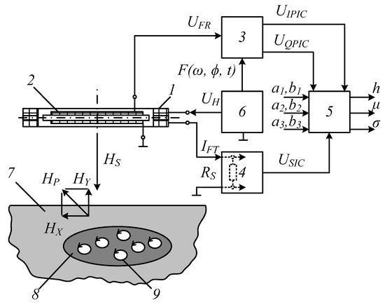
Figure 1.
A schematic block diagram of a thermal protection device with the procedure for extracting DC components from alternating phased voltages and currents: 1 is the frame transmitter (FT); 2 is the ferrite receiver (FR); 3 is the registration and in-phase/quadrature conversion of the signal (induction EMF) from the FR, which uses the primary instrumentation channel (PIC); 4 is the registration and conversion of the impedance response of the transmitting FT as induced by the electromagnetic properties of a buried metal object. The secondary instrumentation channel (SIC) is what converts this response into an electrical signal; 5 is the algorithmic processing of the instrumentation data that determines the BO parameters; 6 is the harmonic signal generator that excites the primary electromagnetic field; 7 is the containing environment; 8 is a BO; 9 are eddy currents; is the magnetic component of the primary electromagnetic field; is the polarized magnetic component of the secondary electromagnetic field; and are the horizontal and the vertical components of the polarized magnetic component of the secondary electromagnetic field; is the measuring shunt; and are the PIC static function coefficients for in-phase conversion; and are the PIC static function coefficients for quadrature conversion; and are the coefficients of the SIC static conversion function; is the data signal (induction EMF) from the FR; and are the in-phase and the quadrature component of the data signal ; is the FT data signal; is the process of synchronizing the PIC conversion procedure to the temporal parameters of the harmonic signal that excites the primary electromagnetic field; and are the specific electrical conductance and the magnetic permeability of the metal object, respectively; is the BO location depth.
Below is the implementation of the method. The sinusoid voltage generator (6) transmits a signal to the frame transmitter (1) to generate the primary electromagnetic field in the surrounding area. By placing the transmitter FT (1) and the receiver FR (2) adjacently, the device generates the primary electromagnetic field and registers the secondary one; the receiver here is a ferrite magnetic antenna: an induction coil with a core of a ferromagnetic material that amplifies the magnetic flux linked to the FR turns. For the lack of a BO (8) in the containing medium (7) to induce zero induction EMF in the FR (2), eliminate the direction FT−FR link by placing the FR axis in the FT plane, which provides geometric compensation for this primary field.
Should a BO (8) emerge in the containing medium (7), the primary field will magnetize it and induce an eddy current (9) in it that will generate a secondary (re-emitted) electromagnetic field with the polarized magnetic component . The secondary field affects FR (2) and induces induction EMF in it to generate the signal . The primary instrumentation channel converts the signal into an in-phase signal and a quadrature signal, where the in-phase signal is proportional to the specific conductance of the BO (8), while the reactive signal is proportional to the magnetic susceptibility of the same. These in-phase and quadrature signals form the PIC output. The PIC-provided conversion procedures are synced to the temporal parameters of the harmonic signal of the sinusoidal voltage generator (6) that excites the primary electromagnetic field.
The induced eddy currents (9) of the BO (8) create a secondary electromagnetic field whose direction is opposite to the exciting field per Lenz’s law. The intensity of the magnetic component in the resulting electromagnetic field will equal the difference between the magnetic-component intensities of the exciting/secondary electromagnetic fields. Thus, provided there is a constant supply voltage of the transmitter (1), the eddy-current electromagnetic field increases its impedance, thus reducing the current flowing through it. Thus, the impedance of the FT (1) will depend on the value and distribution of eddy currents in the BO (8) in the containing medium, i.e., on the specific conductance and the depth , at which the BO (8) is found. In this case, the informative parameter is the amplitude of the FT (1) excitation current. A secondary instrumentation channel registers the changes in the impedance of the emitting antenna FT (1) as induced by the electromagnetic properties of the BO (8).
To that end, the instrumentation shunt of the SIC sends an electrical signal proportional to the excitation current of the FT (1) to be converted further. The resulting signal functions as the SIC output. The next step is to run the data processing algorithm to find the BO parameters. To that end, enter the input data (the coefficients , , and for the static functions of the PIC; and for the static conversion function of the SIC) and process the PIC/SIC output signals jointly. From the algorithm output, find the depth at which the subsurface BO (8) lies, if there is any; identify the BO by finding its magnetic permeability and conductance. To run the data signal-processing algorithm, find all the necessary components when preparing the device by exposing the FR to a predetermined set of references.
In fact, the proposed hybrid subsurface sensing method uses three data channels to collect readings:
- -
- two instrumentation channels from the ferrite receiver to measure the current voltage amplitude for the active component and for the reactive component of the input signal;
- -
- the third instrumentation channel comes from the frame emitter and measures the current amplitude of the exciting current.
This data redundancy does significantly improve the reliability and accuracy of detecting buried metal objects. As a result, subsurface sensing performs better in general.
To better understand the essence of the proposed combined induction sensing method, consider the physical processes behind it.
Consider the functioning of the two FR data channels that form the primary instrumentation channel. According to Faraday’s law, the output voltage of the induction coil can be written as follows for an external re-emitted magnetic field with the amplitude that changes by the harmonic law with the cyclic frequency ω, which amplitude is a function of the physical parameters and [25]:
where j is an imaginary unit; is the effective magnetic permeability of the core; is the magnetic permeability of the vacuum; is the number of turns in the FR induction coil; is the cross-section of the FR core; is the FR core diameter; is the intensity of the magnetic component of the secondary electromagnetic field; and are the specific conductance and magnetic permeability of the BO.
In this case, the following holds true for the magnetic-component intensity of the secondary electromagnetic field provided that on the surface of a conductive BO, this intensity equals some (the magnetic-component intensity amplitude of the primary electromagnetic field) [26]:
where , are the attenuation coefficient and the phase coefficient.
Given that for the case under consideration, the BO conduction current density far exceeds the displacement current (for a purely sinusoidal process), i.e., , one can write:
The Equation (2) ultimately transforms into:
From the properties of the Equations (1) and (2), it appears that the in-phase component of the PIC data signal is mainly proportional to the specific electrical conductance σ of the BO, while the quadrature component of the same is proportional to the magnetic permeability of the BO, thus:
where and are the phase and the cyclic frequency of the FT excitation current; and are the PIC static conversion function for in-phase and quadrature conversion, respectively .
For any transducer such that the output and the input are in the following dependency: , the static conversion function can be written as a generalized mathematical model in the form of a power series around a center of zero:
where is the output value; are the transducer parameters; is the measured value.
In case the output and the input factors are in a dependency of the type , the static conversion function of the transducer should be written as a corresponding polynomial by decomposing it into Taylor series:
where are the constant coefficients of the Equation found by staging and carrying out a passive experiment; is the number of the most significant inputs.
For the case under consideration, where the PIC has virtually no zero signal (zero drift) and features linear conversion, the Equation (7) transforms into:
Given (8), the Equations (4) and (5) can be rewritten as:
where , , and are the coefficients of the static PIC functions for quadrature and in-phase conversion, respectively, found when preparing to scan the containing medium by exposing the FR to a specific set of references.
The values of , , and obtained in this manner are used as inputs when running the data signal-processing algorithm.
Based on (3) and (4), the derived conversion Equations (9) are linearly independent algebraic Equations (the invariance principle), making this a correct and solvable equation system for the desired parameters and .
Consider the SIC conversion procedure, see Figure 2.
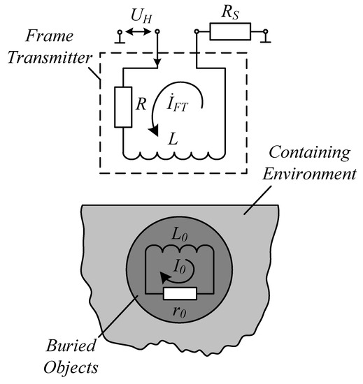
Figure 2.
FT interaction with a BO in the containing medium.
If there is no BO in the containing medium, the following holds true for the FT:
When the FT passes over a buried metal object found in the containing medium, which object has the inductance and the resistance , the magnetic flux originating from the loop current of the generator coil induces the eddy current in the circuit . The loop of the BO and the loop of the FT are thus bound by their mutual induction . An analytical expression for these interconnected loops can be written as:
Given that , the loop current in the BO loop will change to .
Subject the Equation (9) to simple transformations to obtain
where ; , is the depth, at which the BO is found in the containing medium, is the equivalent diameter of the FT, is the mutual induction coefficient for the FT loop and its mirror image at .
The Equation (12) means that the FT impedance components have changed, respectively, to:
Rewrite the Equation (10) in a more generalized form:
where is the value of the altered FT impedance.
According to (13), the signal from the measuring shunt RS can be written as a complex value
Similarly to the Equations (7), the following equation can be written for the conversion procedure performed by the secondary instrumentation channel of the FT (1) in accordance with (12):
where , are the static conversion function coefficients for the secondary instrumentation channel of the FT.
Overall, the measurement process equation system is written as:
The Equation (14), which is part of the algebraic equation system (16), is by virtue of its physical nature linearly independent from the Equations (7). Thus, the system (16) is also correct and solvable with respect to the desired BO parameters:
The obtained expressions (17) are in fact the computational algorithm for finding the BO parameters.
4. Developing the Circuitry of a Metal Detector Based on the Proposed Buried Metal Detection Method
Research produced circuitry for a metal detector with a novel IP design, see Figure 3 for the diagram.
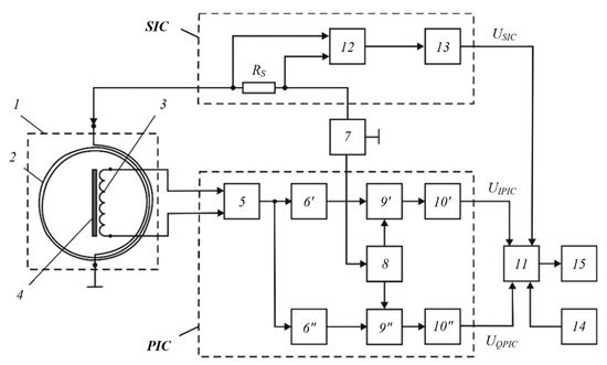
Figure 3.
Metal detector diagram: 1 is the instrumentation probe; 2 is the frame antenna; 3 is the receiver coil; 4 is the ferrite core; 5 is the instrumentation amplifier; 6′ and 6″ are buffer amplifiers; 7 is the generator that produces sinusoidal voltage at sound frequencies; 8 is the generator of quadrature reference voltage; 9′ and 9″ are synchronous detectors (SD); 10′ and 10″ are the ADC units; 11 is the computational unit; 12 is the current meter; 13 is the ADC unit; 14 is data input device; 15 is the indicator; RS is the measuring shunt. The elements (3) and (4) of the probe (1) form the FR. The FT (2) is orthogonal to the receiver coil (3) of the FR to attain the required geometric compensation of the primary field for the FR.
The proposed SU metal detector functions as follows. The frame antenna (7) connected to the sinusoidal voltage generator (7) generates the primary alternating magnetic field that induces eddy currents in the BO, which in turn produce a secondary magnetic field. This field induces EMF in the receiver coil (3) of the FR, which goes to the input of the instrumentation amplifier (5). The output voltage of the amplifier (5) passes through the buffer amplifiers (6)′ and (6)″ to the data inputs of the synchronous detectors (9)′ and (9)″. At the same time, the reference voltages for these synchronous detectors are derived from the operating sinusoidal voltage that is fed from the generator (7) to the input of the generator (8) that produces in-phase or quadrature reference voltage. The outputs of the generator (8) are connected to the reference inputs of the synchronous detectors (9)′ and (9), the outputs whereof are connected via the corresponding ADC units 10′ and 10″ to the data inputs of the register (11), which is in fact a microprocessor computational unit.
Thus, the output of the primary instrumentation channel (PIC) is a data signal that has in-phase and quadrature components: and .
The measuring shunt sends an electrical signal proportional to the FT (2) excitation current that is further read by the current meter 12, which filters and amplifies this signal at the FT excitation frequency while also detecting its amplitude. From the output of the current meter (12), the converted signal goes via the ADC unit (13) to the corresponding data input of the register (11). Thus, the output of the secondary instrumentation channel SIC is the data signal .
The computational unit (11) receives data via the data input device (14). It uses this data to jointly process the signals , , and receive from all the three data inputs; the algorithm thus determines the required parameters of a BO in the containing medium. The output of the computational unit 11 is displayed by the indicator (15).
5. Development and Pilot Testing
In order to test the proposed combined induction sensing method, the research team designed an induction probe (IP) that contained the receiver FR and the FT that had both transmission and reception functions. The FR uses the parametric response of the electromagnetic field to the inner or surficial impedance of the medium, while the FT uses the response of the input impedance of the receiver to the electromagnetic properties of the probed medium; the FR is a single-section magnetic antenna in a coplanar position inside the horizontal FT. Figure 4 shows a general FR/FT-based IP design.
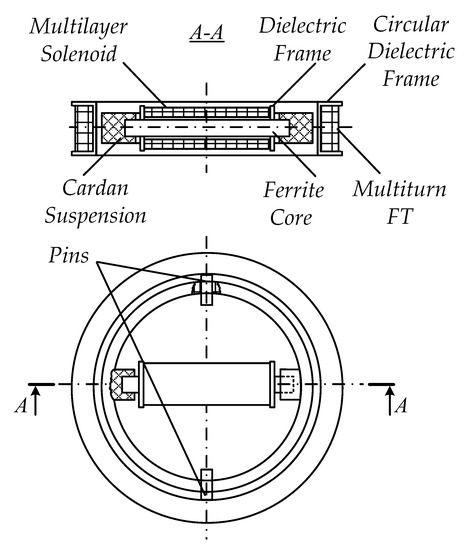
Figure 4.
Layout of an induction probe featuring a frame emitter and a ferrite receiver in a coplanar position.
The IP comprises the flat multiturn FT placed on the circular dielectric frame and the FR that consists of electric winding: multilayer solenoid and dielectric frame, together forming the receiver coil, and the cylindrical ferrite core. The FR is anchored inside the circular frame in its plane by special dielectric sleeves on the dielectric circular cardan suspension, which enables directing the FR sensitivity axis in the required plane. In turn, the cardan suspension is based on the cylindrical pins and that are placed symmetrically on the inner surface of the circular dielectric frame. This design enables an orthogonal placement of the FT and the receiver coil of the FR. Such spatial orientation of the generator frame and the receiver coil will nullify the mutual induction thereof.
The cardan suspension must be on the same order of height as the circular dielectric frame to attain and keep the desired inclination of the FR sensitivity axis with respect to the FT plane so as to attain the required geometric compensation of the primary field. The FR receiver coil and the FT are arranged in the horizontal plane in two steps: first place it roughly by securing the FR receiver coil at a specific point in the ferrite core, then adjust the position using a special microscrew adjuster (not shown in Figure 4).
One version of the described induction probe was made and tested in the process of experimentation. Figure 5 shows an overview of that pilot probe.
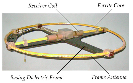
Figure 5.
Pilot induction probe: a design version.
The test BOs were AVVG and VVG quad power cables of finite length (up to 5 m), which had aluminum/copper conductors, insulation and outer shells of PVC. The cables were laid 0.5 to 2 m deep in the ground.
Each of the cable types had a specific design and conductors of three alternative cross-section values for main and for neutral conductors: (1) AVVG/VVG − 3 × 95 + 1 × 50; (2) AVVG/VVG − 3 × 70 + 1 × 35; (3) AVVG/VVG − 3 × 16 + 1 × 10.
The frame antenna was fed with a 60V, 7 kHz variable voltage from an external sinusoidal signal generator, which also synchronized the PIC parameters.
For primary and secondary signal processing, the research team used a special electronic module whose functional units were based on precision operating amplifiers while digital−analog conversion and further numerical (digital) transmission of signals to the register were provided by a standard E502 data collection system manufactured by LCard [27]. This data collection system is actually a universal 16-bit I/o module that supports up to 32 analog and 17 digital signals and feeds them to a PC via high-speed USB 2.0 and 100-Mbit Ethernet interfaces with a conversion rate of up to 2 MHz; it also provides real-time digital processing.
A laptop was used as a portable register; it had software developed to run the instrumentation algorithm and visualize the search procedure.
As noted above, a variety of BOs were used to test the performance of the sensing unit that implemented the proposed combined buried metal detection method; these were buried at specific depths in the containing medium (a sandy and clayey soil). Each cable type was laid one by one in the containing medium to depths of , , , . Figure 6 shows some results of testing buried metal depth detection in containing medium, where h is the depth, is the cross-sectional area of the main (copper—Cu and aluminum—Al) conductors. Measurements were run several times at each depth value; the curve shows arithmetic means connected by smooth, unkinked lines.
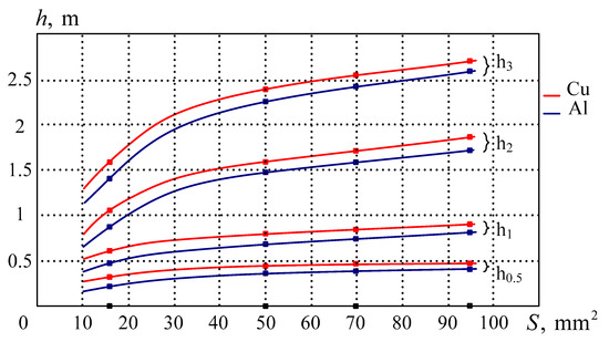
Figure 6.
Measurements at different depths.
The Y-axis shows the depth of metal placement in the containing medium; the detector had to identify these values. The X-axis shows different main-conductor cross-sectional area values of the cable that was placed at different points of the experiment to different depths h in the containing medium; the same metal detector was expected to detect that cable at each specific depth. For instance, for the cable with conductors, the points on the curves show the measured depths h matching in a certain way with the prespecified placement depths (0.5 m; 1 m; 2 m, and 3 m). Similar experiments had been run for other cable types having the same cross-sectional area values. Figure 6 shows that the accuracy of detecting the depth h depends on the material: the more conductive it is, the more accurately it is detected. This is why h values were more accurate for buried copper conductors than for their aluminum counterparts.
Figure 7 shows the distribution of relative depth error for copper conductors varying in the cross-sectional area.
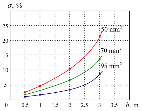
Figure 7.
Distribution of relative depth detection error.
Relative depth detection error peaked at 23% on average at 3 m for the cable whose main conductors (copper) had ; minimum error of 2% was observed for copper conductors.
For the cable where the main conductors were of copper and had , depth was not determined in accurate numbers, as the relative depth detection error was 35% at 0.5 m. Besides, deepening the cable further () forced the metal detector to reach the limits of its sensitivity, meaning it could only detect the presence of metal but not the depth of its placement.
Experimental research thus proved the proposed SU implementation and the developed combined induction sensing method to be efficient.
Note that the research team did not seek to compare this pilot unit against mass-produced metal detectors performance-wise. Further research is planned to develop and optimize hardware based on the proposed sensing method in order to optimize the eigen-parameters of all the nodes and components for better accuracy. This paper describes the pilot unit and the experimental results only as a proof of concept. Therefore, the goal hereof is to highlight the essence and substantiate the theory behind the physical effects upon which the new, unprecedented sensing method is based [28]; besides, this study also tested the feasibility of using the method to find buried metal, identify it, and determine the depth at which it is found in the medium.
6. Conclusions
Thus, the proposed combined method for the detection of buried metal objects actually combines two basic subsurface sensing methods: one based on changes in the electromagnetic field parameters as induced by the inner or surficial impedance of the medium when affected by a propagating magnetic field; and one based on changes in the input impedance of the receiver coil as induced by the electromagnetic properties of the probed medium. Thanks to the data redundancy it provides, the method effectively improves the subsurface sensing performance in general. Implementation of the computational procedures for the proposed dual method would help to detect and identify buried subsurface objects by their specific electrical conductance σ and magnetic permeability while also locating them depth-wise. All of this improves the performance and informativeness of the proposed combined BO detection method while also expanding the range of possible applications.
Experimental research proves the developed combined method for searching for buried metal objects to be efficient and well-performing.
Author Contributions
Conceptualization, I.V.B. (Igor V. Bochkarev) and I.V.B. (Ivan V. Bryakin); methodology, V.R.K.; software, E.A.K.; validation, I.V.B. (Ivan V. Bryakin) and V.R.K.; formal analysis, E.A.K. All authors have read and agreed to the published version of the manuscript.
Funding
This research received no external funding.
Institutional Review Board Statement
Not applicable.
Informed Consent Statement
Not applicable.
Data Availability Statement
Data is contained within the article.
Conflicts of Interest
The authors declare no conflict of interest.
References
- Garrett, C.L. Modern Metal Detectors; Ram Publishing Co.: New York, NY, USA, 1998; p. 432. [Google Scholar]
- Xu, Z.; Meng, G.; Wang, M.; Yang, D.; Wang, S.; Shi, W.; Li, X.; He, J.; Xu, B. Identification of multiple underground metal pipes in short range by means of curve fitting. In Proceedings of the IEEE Industry Applications Society Annual Meeting, Denver, CO, USA, 2–6 October 1994; Volume 3, pp. 2191–2198. [Google Scholar] [CrossRef]
- Flynn, J.J.; Trinkhaus, P. Developments in mine detection. In Proceedings of the EUREL International Conference the Detection of Abandoned Land Mines: A Humanitarian Imperative Seeking a Technical Solution, Edinburgh, UK, 7–9 October 1996; pp. 180–182. [Google Scholar] [CrossRef]
- Won, I.J.; Keiswetter, D.A.; Bell, T.H. Electromagnetic induction spectroscopy for clearing landmines. IEEE Trans. Geosci. Remote Sens. 2001, 39, 703–709. [Google Scholar] [CrossRef]
- Edwards, G. Treasure Hunting with Metal Detectors; Airleaf Publishing: New York, NY, USA, 2006; p. 141. [Google Scholar]
- Thomas, S.; Stone, P.G. Metal Detecting and Archaeology; The Boydell Press: Woodbridge, NJ, USA, 2017; p. 238. [Google Scholar]
- Al-Khalidi, H.; Kalam, A. Reduction in sub-transmission loss using underground power cables. In Proceedings of the Australasian Universities Power Engineering Conference, Sydney, Australia, 14–17 December 2008; p. 6. Available online: https://ieeexplore.ieee.org/document/4813090 (accessed on 1 March 2021).
- Jaw, S.W.; Van Son, R.; Soon, V.K.H.; Schrotter, G.; Kiah, R.L.W.; Ni, S.T.S.; Yan, J. The need for a reliable map of utility networks for planning underground spaces. In Proceedings of the 17th International Conference on Ground Penetrating Radar (GPR), Rapperswil, Switzerland, 18–21 June 2018; p. 6. [Google Scholar] [CrossRef]
- Yamazaki, S.; Nakane, H.; Tanaka, A. Basic analysis of a metal detector. IEEE Trans. Instrum. Measur. 2002, 51, 810–814. [Google Scholar] [CrossRef]
- Liu, B.; Zhou, W. The research of metal detectors using in food industry. In Proceedings of the International Conference on Electronics and Optoelectronics, Dalian, China, 29–31 July 2011; pp. 43–45. [Google Scholar] [CrossRef]
- Garrett, C.L. The Advanced Handbook on Modern Metal Detectors; Ram Publishing Co.: New York, NY, USA, 1985; p. 524. [Google Scholar]
- Sharawi, M.S.; Sharawi, M.I. Design and implementation of a low cost VLF metal detector with metal-type discrimination capabilities. In Proceedings of the IEEE International Conference on Signal Processing and Communications, Dubai, United Arab Emirates, 24–27 November 2007; pp. 480–483. [Google Scholar] [CrossRef]
- Bedenik, G.; Silveira, J.; Santos, Í. Single coil metal detector and classifier based on phase measurement. In Proceedings of the International Symposium on Instrumentation Systems, Circuits and Transducers (INSCIT), Sao Paulo, Brazil, 26–30 August 2019; p. 6. [Google Scholar] [CrossRef]
- Choi, K.N. Two-channel metal detector using two perpendicular antennas. J. Sensors 2014, 412621. [Google Scholar] [CrossRef]
- Rerkratn, A.; Petchmaneelumka, W.; Kongkauroptham, J.; Kraisoda, K.; Kaewpoonsuk, A. Pulse induction metal detector using sample and hold method. In Proceedings of the 11th International Conference on Control, Automation and Systems, Gyeonggi-do, Korea, 26–29 October 2011; pp. 45–48. Available online: https://ieeexplore.ieee.org/abstract/document/6106376 (accessed on 1 March 2021).
- Cheng, Y.; Wang, S.; Zhang, M. Research of miniature magnetic coil sensor used for detecting power cables underground. In Proceedings of the International Conference on Electrical and Control Engineering, Yichang, China, 16–18 September 2011; pp. 6065–6068. [Google Scholar] [CrossRef]
- Wang, P.; Lewin, P.; Goddard, K.; Swingler, S. Design and testing of an induction coil for measuring the magnetic fields of underground power cables. In Proceedings of the IEEE International Symposium on Electrical Insulation, San Diego, CA, USA, 6–9 June 2010. [Google Scholar] [CrossRef]
- Blay, K.R.; Weiss, F.; Clark, D.A.; de Groot, G.J.; Bick, M.; Sen, D. Signal processing techniques for improved performance of a SQUID-based metal-detector. IEEE Trans. Appl. Supercond. 2009, 19, 812–815. [Google Scholar] [CrossRef]
- Jarvi, A.; Leinonen, E.; Thompson, M.; Valkonen, K. Designing Modern Walk-through Metal Detectors. Access Secur. Screen. Chall. Solut. 1992, 21–25. [Google Scholar] [CrossRef]
- Bryakin, I.V.; Bochkarev, I.V.; Khramshin, R.R. Cable avoidance tool. In Proceedings of the International Russian Automation Conference, Sochi, Russia, 8–14 September 2019; p. 7. [Google Scholar] [CrossRef]
- Kim, B.; Han, S.; Kim, K. Planar spiral coil design for a pulsed induction metal detector to improve the sensitivities. IEEE Antennas Wirel. Propag. Lett. 2014, 13, 1501–1504. [Google Scholar] [CrossRef]
- Gvozdev, I.A.; Cvetkov, A.V.; Kondrat’ev, A.V.; Nikitin, A.A. Induction Cable Tracer. RF Patent No. 2234111, G01V 3/11, 10 August 2004. [Google Scholar]
- Ganesh, M.; Ravan, M.; Amineh, R.K. Electromagnetic induction imaging at multiple depths with a single coil. IEEE Trans. Instrum. Meas. 2021, 70, 4502809. [Google Scholar] [CrossRef]
- Ravan, M.; Amineh, R.K.; Hussein, A.; Simanov, O.; Agarwal, A. Electromagnetic induction imaging of metallic objects at multiple depths. IEEE Magn. Lett. 2020, 11, 2100405. [Google Scholar] [CrossRef]
- Woan, G. The Cambridge Handbook of Physics Formulas; Cambridge University Press: New York, NY, USA, 2003; 220p. [Google Scholar]
- Morrish, A.H. The Physical Principles of Magnetism; Wiley-IEEE Press: New York, NY, USA, 2001; p. 696. Available online: https://ieeexplore.ieee.org/book/5263396 (accessed on 1 March 2021).
- Measuring Voltage Converters E-502. User Manual. Available online: https://www.manualslib.com/manual/1598795/L-Card-Adc-Series.html (accessed on 1 March 2021).
- Bryakin, I.V.; Bochkarev, I.V. Hybrid Method for Detecting Subsurface Metal Objects. RF Patent No. 2743495, G01V 3/11, 19 February 2021. [Google Scholar]
Publisher’s Note: MDPI stays neutral with regard to jurisdictional claims in published maps and institutional affiliations. |
© 2021 by the authors. Licensee MDPI, Basel, Switzerland. This article is an open access article distributed under the terms and conditions of the Creative Commons Attribution (CC BY) license (https://creativecommons.org/licenses/by/4.0/).