Article

Aeroelastic Response of Aircraft Wings to External Store Separation Using Flexible Multibody Dynamics

Department of Mechanical Engineering, Imperial College London, London SW7 2AZ, UK
Machines 2021, 9(3), 61; https://doi.org/10.3390/machines9030061
Submission received: 30 January 2021 / Revised: 21 February 2021 / Accepted: 11 March 2021 / Published: 13 March 2021
(This article belongs to the Special Issue Dynamic Stability Analysis of Aerospace Structures)

Abstract

:
In aviation, using external stores under the wings is a common method of carrying payload or fuel. In some cases, the payload can be rigidly attached to the wing. However, stores must often be ejected during flight for aircraft, such as military type, which carry drop tanks and missiles. This may cause the wing to respond dynamically with increasing amplitudes, due to the impulsive load of ejection and the change of total mass. This is especially critical in aircraft with highly flexible wings, such as those with high aspect ratios. In this case, it is crucial to evaluate the wing response to store separation, which requires a suitable simulation environment that is able to support nonlinear and multidisciplinary analysis. To address such a need, this work presents the use of flexible multibody dynamics in the simulation of wing response to store separation. To demonstrate, a highly compliant wing was selected with a rigid body that was mounted on the wing to represent an external store. The time marching simulation of the wing before and after the store separation was presented to show the features and benefits of the method.

1. Introduction

An external store is a component that is required when there is no available space inside an aircraft’s body. A classic application of external stores is to the weapons or drop tanks used in combat aircraft, which have been very common since the early days of aviation [1]. Recently, unmanned aerial vehicles (UAVs) have also started carrying wing-mounted stores, which are typically weapons for combat purposes [2]. With an increasing future interest in UAVs [3], especially due to them being a low-cost alternative to conventional combat aircraft [4], it is expected that the adoption of this role will continue to increase. In brief, manned and unmanned aircraft both carry external stores for ejection at some point during a mission.
These external stores are usually positioned under the wing, alhough sometimes under or above the fuselage is preferred. Depending on the store weight, size, and geometry, store separation causes two consequences: (i) a change in aircraft configuration and, hence, wing behavior, and (ii) the transient response of the wing and store during the short period of the separation process. Whilst the first case can be considered to be two distinct aircraft, the latter should consider the two configurations. Therefore, the store ejection has an intrinsic characteristic that should be handled cautiously. In particular, the separation of external stores from an aircraft wing during flight is a safety concern. An obvious issue is the strike of the store after being released. To address this, the trajectory of the stroke needs to be carefully estimated. This is usually achieved through conducting high fidelity computational fluid dynamics simulations [5,6]. In most safe separation studies, the wing is assumed to be rigid. Still, there are some works that consider the effect of wing elasticity on the store separation process [7,8,9]. In these studies, the focus is on the store trajectory, rather than the response of the wing.
In addition to the wing-store strike, the response of the wing to the store separation due to impulsive load induced by the ejection and change in the mass distribution carried by the structure is another safety issue. There are no reported incidents that are related to wing response to store separation, but recent works show that there is an increased interest in this problem due to the prevalence of more compliant wing structures. For example, dynamic loads that are associated with local impulsive excitation are obtained using mode displacement and force summation methods in refs. [10,11] investigated the aeroelastic behavior of wings due to store ejection using fluid–structure coupling. The structural model is a linear model that is obtained using a Finite Element Method. Additionally, a frequency-domain method using linear FEM is used in Ref. [12] to compute wing response. Linear structural models could provide accurate results for relatively stiff wings. However, as wing compliance increases, this could lead to moderate and large deformations. As a result, non-linear behavior may arise due to changes in structural, dynamic, and aerodynamic loads. Therefore, the resulting wing response could be very different from that of a linear structure. As in the case of any non-linear dynamical system, the wing could experience limit cycle oscillations or chaotic response [13,14]. Therefore, the assumption of linearity can result in misleading results as the non-linear effects due to the wing flexibility increasing. A better approach would be to use a method that can support nonlinear simulations.
The problem of store separation is, in general, time-dependent and non-linear. Such problems could be handled using spectral methods [15,16] or time marching simulations. This work prefers the latter and it presents the use of flexible multibody dynamics to simulate the wing aeroelastic response to store separation. When considering the efficient handling of large deformations and rotations and the ease of simulating non-linear time-dependent problems, flexible multibody dynamics is a promising method in solving aircraft store separation problems. To the author’s knowledge, this work is the first utilization of multibody dynamics in the stability assessment of aircraft wings releasing external stores during flight. A solver with an extensive aeroelastic library was selected to achieve realistic results, which includes geometrically exact beam formulations, and static and unsteady aerodynamics. The aeroleastic response of the wing is analyzed using time marching simulations of the wing, both with and without store separation.
The contents of the paper are organized, as follows. Section 2 describes the method and presents a verification of the method using a simple mechanical system. In Section 3, a high aspect ratio aircraft is explained to show the basic elements that are used to model the problem. Section 4 presents the analysis results and demonstrates the use of multibody dynamics in the dynamic response analysis of a high aspect ratio wing. Section 5 concludes the paper.

2. Method

This section describes the method of simulating a high aspect ratio wing response to store separation and then verifies its use for the separation aspect using a two degree of freedom model.

2.1. Multibody Dynamics

Aircraft wings are lightweight structures, and some are even specially made compliant to increase payload carrying capacity or flight efficiency. As a result, wings can demonstrate non-linear behavior with moderate to large deformations. Additionally, store separation changes the configuration of the simulation model, which requires special attention. Therefore, the method that is used to compute the wing response to store separation should be a non-linear and comprehensive solver. This work uses MBDyn open-source multibody dynamics code [17]. MBDyn has been developed at the Aerospace Science and Technology Department of Politecnico Di Milano and it contains a wide range of elements, including an extensive fixed and rotary wing aeronautics library. MBDyn simulates heterogeneous dynamical system that are based on first principles. In other words:
M x ˙ = p
p ˙ = f ( x ˙ , x , t ) + ϕ / x T λ
ϕ ( x ) = 0
differential algebraic equations are directly solved [18]. MBDyn can provide the following capabilities to its users:
  • nonlinear dynamics of rigid and elastic bodies;
  • geometrically exact beam and shell elements;
  • lumped and super elements;
  • smart materials, electric and hydraulic networks and active control;
  • essential fixed-wing and rotorcraft aerodynamics; and,
  • links to external solvers for co-simulation of multiphysics problems, such as Computational Fluid Dynamics (CFD) and terradynamics.
Being an open-source code, MBDyn is extensively used in research and development. Some examples include aircraft maneuver simulations with coupled CFD [19], the simulation of tiltrotor flight mechanics [20], aeroservoelastic analysis of wind turbines [21], and the trajectory optimization of robotics [22].

2.2. Verification

Multibody dynamics is a well-established discipline of computational mechanics and it has been verified and validated extensively against problems of distinct characteristics and variable complexity. Still, the separation of two bodies using MBDyn has not been done, and there is a need to verify the approach on a simple problem before applying it to a complex multidisciplinary problem regarding the separation of two bodies. To demonstrate the capability of the method in solving store separation, experiments that are conducted in a wind tunnel would be the most suitable way. In the absence of the necessary resources, an alternative would be to verify against an analytical solution. The latter approach is acceptable, since the simulation tool has been verified in many complex problems [23,24,25] and only the separation aspect of the problem needs further attention.
For this purpose, a two degree of freedom system mass-spring-damper lumped parameter model was selected, as shown in Figure 1. In this form, the two degree of freedom model has an analytical solution and, hence, can be easily compared to a solution obtained using multibody dynamics. Figure 1 presents the schematic of the verification problem. The problem consists of two masses, one of which ( m 1 ) is connected to the ground by a spring ( k 1 ) and damper ( c 1 ). The grounded mass is connected to another mass ( m 2 ), which is free on its other side. In the initial condition, these two masses were interconnected by spring ( k 2 ) and damper ( c 2 ) elements. There is harmonic forcing on ( m 1 ) at a 20 Hz excitation frequency. At 0.5 s, the interconnecting spring and damper connection was deactivated to observe the response before and after the separation. Equation (4) gives the equations of motion, with the numerical values of the parameters being reported in Table 1.
m 1 0 0 m 2 x ¨ 1 x ¨ 2 + c 1 + c 2 c 2 c 2 c 2 x ˙ 1 x ˙ 2 k 1 + k 2 k 2 k 2 k 2 x 1 x 2 = f 1 0
The lumped parameter system shown in Figure 1 was modeled in the MBDyn environment to demonstrate how a similar analysis can be conducted in a multibody software, proving its validity by comparing the simulation results with that of the analytical solution. In the MBDyn framework, this system consisted of two rigid structures, three structural nodes, five joints, and one force. The ‘total pin’ joints were located between the ground and main body and store and ground, to constrain the two translational and three rotational motions. Two ‘rod’ joints were used to represent the linear spring and dampers. An ‘absolute force’ was applied in the form of a sine wave at 20 Hz on the main body. In the store separation analysis, the mass was released at the specified time. The ’driven’ element was used to separate the store from the main body at a given time that is prescribed in the input file. The multibody model was simulated using MBDyn, and the resulting displacements, velocities, and accelerations were recorded.
Figure 2 shows the simulation results for both rigid bodies. Before the separation, they both have almost identical motion due to the very rigid spring connection. After the two masses were separated, the forces acting on the released mass ( m 2 ) vanishes, and it follows a constant velocity motion, which is exactly equal to the velocity at the instant of separation. On the other hand, although there is still forcing applied on the ( m 1 ), the amplitude of its motion changes. The resulting displacement amplitudes of ( m 1 ), which are obtained independently while using the analytical solution and multibody dynamics simulation, are compared in Table 2. The reported values are identical, which verifies the discontinuity aspect of the separation problem.

3. Demonstration Model

This section describes the aircraft wing that was used in the analysis. Firstly, the aircraft is described, and then the multibody dynamics realization of the aircraft wing model is explained.

3.1. Aircraft

The proposed approach can be used in any type of aircraft and wing. Having said this, highly compliant structures can benefit from the method more than relatively stiff wings, as the former types are likely to exhibit nonlinear behavior due to moderate and large deformations. For this purpose, a high aspect ratio was judged to be more suitable as an example, since it is expected to be highly compliant to sudden time dependent forces, as experienced by the wing after the release of an external mass. As a result, the benefit of using a fully nonlinear solver could be more easily demonstrated. Consequently, an unmanned aircraft with a high aspect-ratio wing was selected as the demonstration vehicle, as presented in Figure 3.
The aircraft of interest is a high-altitude long-endurance (HALE) unmanned aircraft and it has been previously studied for generalized eigen-analysis in Ref. [26] and for limit cycle oscillations in Ref. [13]. Having highly compliant wings, this aircraft is a good candidate to demonstrate the wing response to store separation. Because this work focuses on the wing response, the fuselage was not included and a single cantilever wing was considered, with the numerical values that are reported in Table 3. An external store under the wing is considered with the parameters that are given in Table 4. The wing is simulated at a high altitude flight condition, the conditions of which are available in Table 5.

3.2. MBDyn Model Description

The wing model without the store, and its separation process, was previously developed while using MBDyn [17,26] with the elements that are presented in Figure 4. Additional features were added to this model to simulate the wing response to store separation. Namely: stores, the store-wing connection, and drive element to release the store. The final overall multibody dynamic model consists of the following:
  • Simulation parameters: time step, final time, solution tolerances, and iteration limits.
  • Structural model: 16 three-node finite-volume beam elements [27] defined the 16 m span wing structure. The whole wing structure required 32 nodes for structural discretization, each was assigned inertial properties.
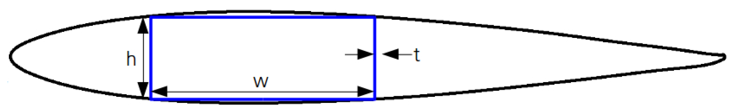
  • Beam cross-section: properties were given as a diagonal (6 × 6) constitutive law matrix, which remains constant along the span.
  • Aerodynamic model: the wing was discretized by aerodynamic elements formulated by lifting line theory. The aerodynamic elements included both steady and unsteady aerodynamics, therefore helping to achieve realistic static deflection and dynamic response.
  • Boundary condition: ground joint was used to support the wing root.
  • Store: a rigid body at X s t o r e = 7 m spanwise location was defined to represent the store, which was connected to the wing via spring and damper, as shown in Figure 5. The store has no aerodynamic model attached to it.
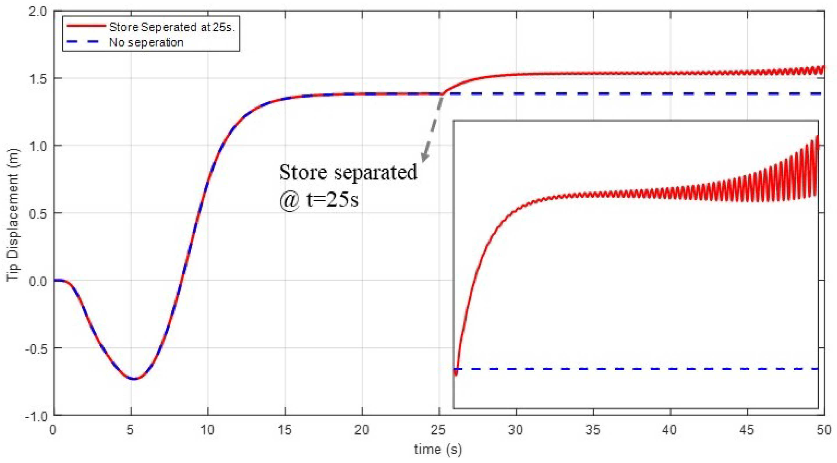
  • Separation: the driven element was used to keep the store connected to the wing for t < 25 s. 25 s was defined based on the time required to achieve the steady-state solution of the same wing under the same flight conditions.
  • Gravity: introduced to achieve realistic wing static response of a highly flexible wing and motion of the store after separation.
Figure 4. Modeling elements used in aeroelastic wing-store multibody model.
Machines 09 00061 g004
It should be noted that MBDyn has an extensive library of mechanical parts, joints, and forcing options [17]. Additional elements could be added to make the model more complex. For example, the rod connection could include dedicated joints, friction, or an impulsive force could be included at separation. However, within the scope of this work and the available data, the above multibody dynamics models can be considered to be sufficient in terms of the essential components.

4. Results and Discussion

This section presents the results that were obtained using the model described in the previous section to demonstrate the benefits of using multibody dynamics in aircraft wing response to store separation.

4.1. Simulation without Store Separation

The first results present the simulation of the wing-store configuration to explain the distinct characteristics of the simulation. The displacement of the wing tip was obtained from the simulation and is shown in Figure 6. The simulation starts at t = 0 s and the tip starts from a reference position. When the simulation starts, the gravity and the flight speed are introduced gradually, rather than instantly, to aid with convergence. Gravity dominates just after initiation as the wing flaps down, being mainly resisted by the elastic forces. However, as the aerodynamic forces build up with increased airspeed, the wing recovers and the wingtip moves upwards. Gravity, aerodynamic, and elastic forces come to equilibrium near t = 20 s, after which the wingtip position remains constant.

4.2. Wing Response to Store Separation

Figure 7 presents the response of the wingtip before and after the store separation, which is compared to that of the ‘no separation’ case. At t = 25 s , the store is released from the wing. As a result of weight change, an impact load acts on the wing and the wing tip moves up and starts oscillating. The oscillations are unstable in nature with increasing amplitude, while the ‘no separation’ case remains constant, which implies a stable blade. This result could be attributed to the non-linearities of the whole system as a result of the change in wing state after separation.
It is also worth looking at the deformed shape of the wing. Figure 8 shows the displacement at the beam nodes, which, in turn, defines a displacement shape. Initially, the wing nodes form a straight line at t = 0 s. As the gravity dominates, but is resisted by the elastic forces, the wing flaps down and comes to a lower state around t = 5 s . Subsequently, the aerodynamic loads build up and, consequently, the wing flaps up. This continues until the wing reaches steady-state. Right after the separation, the wing starts an instant upward movement. As the time increases, the amplitude of wing displacement gains amplitude and the solution diverges eventually.
With Figure 8, it can be observed that, as the amplitude increases, the oscillatory component of the motion is not visible. In order to better observe the time-dependent motion that the wing undergoes, the oscillatory wing deformation was obtained by subtracting the steady wing motion just before the separation from the total displacement. Consequently, Figure 9 presents wing oscillatory motion after the store is released. The displacement shapes were identified at different time steps within the same cycle (near 50 s ). The curves suggest that the oscillatory motion is a combination of the typical first and second bending modes of a cantilever beam.

4.3. Stability Enhancement

Two analyses were conducted in order to demonstrate how the suggested method can be used to improve the stability of the wing motion after store separation.

4.3.1. Wing Stiffening

Increasing structural stiffness is an obvious choice for stabilizing the wing. To achieve this, a symmetric rectangular thin-walled beam was assumed inside the wing, as shown in Figure 10. This could be seen as an oversimplified assumption, since aircraft wings are much more complex than a box beam representation. Nevertheless, considering that the beam constitutive matrix was symmetric and constant throughout the wing in the original model, a simple box beam assumption could be acceptable within the scope of this work. It should also be noted that the proposed method could be used in parallel to advanced wing geometries as long as the cross-section constitutive matrix is provided. However, the objective here is to estimate the required amount of increase in the stiffness of the wing, leading to reductions in the oscillations after store separation. For this reason, the constitutive matrix needs to be modified. Consequently, the change in the box-beam thickness was related to the change in the area, moment of the cross-section area, and wing mass.
Figure 11 shows the tip response of the wing in its original stiffness and modified version after increasing the thickness. Whilst the upper plot presents the full simulation, the lower plot focuses on the oscillatory response by focusing on the final time steps. It is clear from the lower plot that the oscillations of the wing reduce as the wing becomes stiffer with an increasing thickness. It can also be observed that there are no oscillations when the box-beam thickness of the wing is increased by 6%. Such analyses, with more sophisticated finite element models of the cross-section, can be helpful, when a wing is not initially designed for store separation, but later decided to do so. The amount of wing design changes that are required to preserve the stability characteristics could be identified.

4.3.2. Vibration Control

While structural modifications can enhance stability, the wing can also be equipped with sensors and actuators to control the vibrations [28]. MBDyn can support such an analysis through its control elements. There is no linearization requirement and the controller can take effect during the time marching simulations. For this purpose, the proportional–integral–derivative (PID) control was implemented. Based on the measured acceleration at the wing tip, a control moment was applied to twist the blade and attenuate the oscillations, as shown in Figure 12. This can be stated as [29]:
m ( t ) = K p ( t ) e ( t ) + K i 0 t e ( τ ) d τ + K d de ( t ) dt
where
K p , K i , K d are the proportional, integral, and derivative gains,
m ( t ) is the control moment applied close to the wing root,
e ( t ) is the error, which is tip acceleration in this case,
t is the time.
Figure 12. A simplified representation of wing control.
Machines 09 00061 g012
The upper plot of Figure 13 presents the response of the wing after store separation and focuses on wingtip oscillations for controlled and uncontrolled cases. It can be observed that the amplitude of oscillations increases without limit in the uncontrolled case, while no oscillations appear in the controlled case. The controller is active and the bottom plot of Figure 13 presents the required moment. At the point of separation, the controller takes effect and suddenly increases the amplitude of the moment to approximately 9 N m . A few steps are required to control the wing, with decreasing amplitude of control moment, which eventually vanishes.

5. Conclusions

This work examined the dynamic response of a high aspect ratio wing due to the separation of an externally supported store using flexible multibody dynamics. MBDyn, an open-source multibody dynamics tool, was used to model a nonlinear aeroelastic wing model, and then model the commands that release the store at a given time after the wing reaches a steady-state solution. A high aspect ratio wing, carrying a load, was used to demonstrate the benefits of using the suggested approach. The analysis showed the following:
  • The wing response, which is stable before the response, could be unstable after the separation of the external store.
  • A preliminary investigation on wing stiffness showed that a 6 percent increase in the wing structural mass is required to achieve a stable wing.
  • As an alternative to the wing stiffening, the diverging wing response after the store separation could be stabilized using a controller. In this case, a moment with maximum 9 N m amplitude is required.
This work could be followed by more complicated analysis to achieve a better understanding of the problem and to address other issues that are likely to occur after external stores are released from aircraft wings. Using the suggested method and the developed model as a basis, possible additions can be made, which are briefly mentioned, as follows:
  • The simulations can be repeated for a flying aircraft, including the rigid body motion, fuselage vibrational modes, and flight mechanics derivatives.
  • The store can be given aerodynamic characteristics to include the effects of store aerodynamics on the wing stability.
  • The store location, store mass, wing airfoil, and the wing structure can be optimized for a safe store separation, while ensuring that the payload carrying capacity of the aircraft is kept the same.
  • A flight envelope for stable store separation could be achieved.

Funding

Article Processing Charges were funded by Imperial College London.

Acknowledgments

The author thanks Daghan Burak Malkoc for his efforts at his internship at Politecnico Di Milano. The fruitful discussions Andrea Zanoni and Pierangelo Masarati are greatly acknowledged. Author also thanks Tom Mace for his help in editing the text.

Conflicts of Interest

The author declare no conflict of interest.

References

  1. Fredriksen, J.C. International Warbirds: An Illustrated Guide to World Military Aircraft (1914–2000); ABC-CLIO: Santa Barbara, CA, USA, 2001. [Google Scholar]
  2. Gupta, S.G.; Ghonge, M.M.; Jawandhiya, P.M. Review of Unmanned Aircraft System (UAS). Int. J. Adv. Res. Comput. Eng. Technol. (IJARCET) 2013, 2, 1648–1658. [Google Scholar] [CrossRef]
  3. Anonymous. Unmanned Aircraft Systems Roadmap 2010–2035; DoD, US Department of Defense: Fort Rucker, AL, USA, 2010. [Google Scholar]
  4. Valanis, K.; Vachtsevanos, G.J. (Eds.) Handbook of Unmanned Aerial Vehicles; Springer: Dordrecht, The Netherlands, 2015. [Google Scholar]
  5. Lijewski, L.E.; Suhs, N.E. Time-accurate computational fluid dynamics approach to transonic store separation trajectory prediction. J. Aircr. 1994, 31, 886–891. [Google Scholar] [CrossRef]
  6. Lasek, M.; Sibilski, K.; Lasek, M. Modelling of External Store Separation. In Proceedings of the 40th AIAA Aerospace Sciences Meeting & Exhibit, Reno, NV, USA, 14–17 January 2002. [Google Scholar] [CrossRef]
  7. Mizrahi, I.; Raveh, D.E. Wing Elasticity Effects on Store Separation. J. Aircr. 2019, 56, 1231–1249. [Google Scholar] [CrossRef]
  8. Hua, R.; Zhao, C.; Ye, Z.; Science, Y.J.A. Effect of Elastic Deformation on the Trajectory of Aerial Separation. Aerosp. Sci. Technol. 2015, 45, 128–139. [Google Scholar] [CrossRef]
  9. Kozak, M.T.; Yildiz, E.N.; Yazicioglu, Y.; Cigeroglu, E. Effects of Aircraft Aeroelastic Deformations on External Store Separation Dynamics. In Proceedings of the ASME 2013 International Mechanical Engineering Congress and Exposition, San Diego, CA, USA, 15–21 November 2013. [Google Scholar] [CrossRef]
  10. Karpel, M.; Presente, E. Structural dynamic loads in response to impulsive excitation. J. Aircr. 1995, 32, 853–861. [Google Scholar] [CrossRef]
  11. Zhang, S.; Meganathan, A.; Jain, K.; Fuchiwaki, T. Effects of Store Separation on the Aeroelastic Behavior of Wings. In Proceedings of the 26th AIAA Applied Aerodynamics Conference, Honolulu, HI, USA, 18–21 August 2008. [Google Scholar] [CrossRef]
  12. Kariv, D.; Raveh, D.E. Dynamic Response of an Elastic Aircraft to Ripple Store Ejection. J. Aircr. 2020, 57, 635–651. [Google Scholar] [CrossRef]
  13. Patil, M.J.; Hodges, D.H.; Cesnik, C.E.S. Limit-Cycle Oscillations in High-Aspect RAtio Wings. J. Fluids Struct. 1999, 15, 107–132. [Google Scholar] [CrossRef]
  14. Tamer, A.; Masarati, P. Aeroelastic Stability Estimation of Control Surfaces with Freeplay Nonlinearity. Aerotec. Missili Spaz. 2017, 96, 154–164. [Google Scholar] [CrossRef]
  15. Tamer, A.; Masarati, P. Stability of Nonlinear, Time-Dependent Rotorcraft Systems Using Lyapunov Characteristic Exponents. J. Am. Helicopter Soc. 2016, 61, 14–23. [Google Scholar] [CrossRef]
  16. Masarati, P.; Tamer, A. Sensitivity of trajectory stability estimated by Lyapunov characteristic exponents. Aerosp. Sci. Technol. 2015, 47, 501–510. [Google Scholar] [CrossRef] [Green Version]
  17. MBDyn: Multibody Dynamics. Available online: http://www.mbdyn.org/ (accessed on 13 March 2021).
  18. Masarati, P.; Morandini, M.; Mantegazza, P. An efficient formulation for general-purpose multibody/multiphysics analysis. J. Comput. Nonlinear Dyn. 2014, 9, 041001. [Google Scholar] [CrossRef]
  19. Cavagna, L.; Masarati, P.; Quaranta, G. Coupled Multibody/Computational Fluid Dynamics Simulation of Maneuvering Flexible Aircraft. J. Aircraft 2011, 48, 92–106. [Google Scholar] [CrossRef]
  20. Mattaboni, M.; Masarati, P.; Quaranta, G.; Mantegazza, P. Multibody Simulation of Integrated Tiltrotor Flight Mechanics, Aeroelasticity, and Control. J. Guid. Control. Dyn. 2012, 35, 1391–1405. [Google Scholar] [CrossRef]
  21. Cavagna, L.; Fumagalli, A.; Masarati, P.; Morandini, M.; Mantegazza, P. Real-Time Aeroservoelastic Analysis of Wind-Turbines by Free Multibody Software; Springer: Dordrecht, The Netherland, 2011; Volume 23, pp. 69–86. [Google Scholar] [CrossRef]
  22. Attolico, M.; Masarati, P.; Mantegazza, P. Trajectory Optimization and Real-Time Simulation for Robotics Applications. In Proceedings of the Multibody Dynamics 2005, ECCOMAS Thematic Conference, Madrid, Spain, 21–24 June 2005. [Google Scholar]
  23. Gundling, C.; Sitaraman, J.; Roget, B.; Masarati, P. Application and validation of incrementally complex models for wind turbine aerodynamics, isolated wind turbine in uniform inflow conditions. Wind Energy 2015, 18, 1893–1916. [Google Scholar] [CrossRef]
  24. Morandini, M.; Masarati, P. Implementation and Validation of a 4-Node Shell Finite Element. In Proceedings of the ASME 2014 International Design Engineering Technical Conferences and Computers and Information in Engineering Conference, Buffalo, NY, USA, 17–20 August 2014. [Google Scholar]
  25. Bauchau, O.A.; Wu, G.; Betsch, P.; Cardona, A.; Gerstmayr, J.; Jonker, B.; Masarati, P.; Sonneville, V. Validation of Flexible Multibody Dynamics Beam Formulations using Benchmark Problems. In Proceedings of the 3rd Joint International Conference on Multibody System Dynamics–IMSD, Busan, Korea, 30 June–3 July 2014. [Google Scholar]
  26. Ripepi, M.; Masarati, P. Reduced Order Models Using Generalized Eigenanalysis. Proc. Inst. Mech. Eng. Part K 2011, 225, 1–14. [Google Scholar] [CrossRef]
  27. Ghiringhelli, G.L.; Masarati , P.; Mantegazza , P. A multi-body implementation of finite volume beams. AIAA J. 2000, 38, 131–138. [Google Scholar] [CrossRef]
  28. Prakash, S.; Renjith Kumar, T.; Raja, S.; Dwarakanathan, D.; Subramani, H.; Karthikeyan, C. Active vibration control of a full scale aircraft wing using a reconfigurable controller. J. Sound Vib. 2016, 361, 32–49. [Google Scholar] [CrossRef]
  29. Astrom, K.J.; Wittenmark, B. Computer-Controlled Systems; Dover: Mineola, NY, USA, 2011. [Google Scholar]
Figure 1. A 2-DOF mass-spring-damper system before (a) and after (b) the separation of the second mass.
Machines 09 00061 g001
Figure 2. Response of two bodies before separation and after separation at 0.5 s.
Machines 09 00061 g002
Figure 3. Geometric representation of high altitude long endurance unmanned air vehicle [26].
Machines 09 00061 g003
Figure 5. Store and its connection to the wing (not to scale).
Machines 09 00061 g005
Figure 6. Tip response of wing without separation.
Machines 09 00061 g006
Figure 7. Tip response after store separation as compared to the no-separation case.
Machines 09 00061 g007
Figure 8. Displacement shape of the wing at different times.
Machines 09 00061 g008
Figure 9. Wing oscillatory motion identified at different time steps within the same cycle.
Machines 09 00061 g009
Figure 10. Box beam model to scale the thickness for stable wing response.
Machines 09 00061 g010
Figure 11. Tip response of the wing considering three different box beam thickness values.
Machines 09 00061 g011
Figure 13. Tip response of the wing for controlled and uncontrolled cases and the resulting control moment.
Machines 09 00061 g013
Table 1. Store Separation Verification Parameters.
ParameterValue
Mass ( m 1 , m 2 )7000, 500 (kg)
Stiffness ( k 1 , k 2 ) 1 × 10 8 , 1 × 10 8 (N/m)
Damping ( c 1 , c 2 ) 1 × 10 5 , 1 × 10 5 (kg × rad/s)
Force on main body3750 (N) at 20 Hz.
Time of store separation0.5 s
Table 2. Comparison of the steady displacement response that was obtained using multibody solution and the analytical solution.
Displacement Amplitude
before Separation
Displacement Amplitude
after Separation
MBDyn Simulation0.29 mm0.24 mm
Analytical Solution0.29 mm0.24 mm
Table 3. Parameters of the aircraft model [26].
ParameterValue
Time of store separation25 s
Half-span16 m
Chord1 m
Mass per unit length0.75 kg/m
Moment of inertia (%50 chord)0.1 kgm
Span-wise elastic axis%50 chord
Center of gravity%50 chord
Bending rigidity 2 × 10 4 Nm 2
Torsional rigidity 1 × 10 4 Nm 2
Bending rigidity (Chordwise) 4 × 10 6 Nm 2
Altitude20 km
Density of air0.0889 kg/m 3
Table 4. Numerical values of the store.
ParameterValue
Mass of Store10 kg
Store Support Stiffness 1 × 10 8 N / m
Store location with respect to the wing root7 m
Table 5. Flight Condition.
ParameterValue
Altitude20 k m
Air Density0.089 k g / m 3
Flight Speed40 kn
Publisher’s Note: MDPI stays neutral with regard to jurisdictional claims in published maps and institutional affiliations.

