Abstract
The precise evaluation of the system design and characteristics is a challenge for experts and engineers. This paper considers the problem of the development and application of a digital twin to assess cyberphysical systems. We analyze the details of digital twin applications at different lifecycle stages. The work reviews and summarizes properties of models concerning the digital and physical components of a cyberphysical system (CPS). The other issue of a CPS is increasing cybersecurity threat for objects, so special attention is paid to the heterogeneous digital twin usage scenarios to improve CPS cybersecurity. The article also details the heterogeneous digital twin’s implementation for a real upper-level control system of a nuclear power plant. The presented heterogeneous digital twin combines virtual machines with real equipment, namely hardware-in-the-loop (HiL) components. The achievements and drawbacks of the implemented model, including single timescale maintaining challenges, are discussed.
1. Introduction
The idea of Industry 4.0 and the term itself were phrased for the first time in Germany, in 2011, by the working group on the vision of industry development prospects [1]. The group performed the activity on an assignment of the German government. In a small period, the idea and the term have become widespread. In that period, other countries had performed researches of a similar kind as well, and the idea under discussion is also known as industrial internet, advanced manufacturing, smart industry, smart manufacturing, etc. [2]. The authors of the concept [3] consider the industrial enterprise of the future as a flexible and adaptable cyberphysical system (CPS) that unites manufacturing, warehousing, and logistics through the medium of the Internet of Things (IoT).
The list of digital technologies that a manufacturing company of Industry 4.0 should use includes (see, for example [2,4,5]) cloud and fog computing, artificial intelligence and mobile autonomous robots, virtualization, new data transmission protocols for the IoT, and many others. These technologies are intended to make up a CPS that integrates digital resources and physical, real objects into a consistent environment.
One of the technologies that became a part of Industry 4.0 cyberphysical industrial systems is the digital twin technology. While it is already widely used today, there is no well-established single definition of the term “digital twin” yet. For example, IBM [6] defines a digital twin as “a dynamic virtual representation of a physical object or system, usually across multiple stages of its lifecycle. It uses real-world data, simulation or machine learning models, combined with data analysis, to enable understanding, learning, and reasoning. Digital twins can be used to answer what-if questions and should be able to present the insights in an intuitive way.” The Industrial Internet Consortium [7] states that “a digital twin is a formal digital representation of some asset, process or system that captures attributes and behaviors of that entity suitable for communication, storage, interpretation or processing within a certain context.” The W3C definition [8] seems to us more reflected to the practical aspects of realization of digital twins of instrumentation and control systems (I&C systems): “A digital twin is a virtual representation of a device or a group of devices that resides on a cloud or edge node. It can be used to represent real-world devices which may not be continuously online, or to run simulations of new applications and services, before they get deployed to the real devices.”
We share the common view that a digital twin should have some general properties. Following the Industrial Internet Consortium white paper [7] and Tao et al. [9], present some of them:
- A digital twin may follow its real counterpart at various lifecycle stages or during a single lifecycle stage.
- A digital twin should have a connection with its real counterpart and collects the data from the real-world object.
- A digital twin “should enable computational and analytic models to analyze these data to describe, diagnose, predict and simulate the states and behaviors of the real-world objects and systems” [7].
High-risk enterprises are usually more conservative in the choice of technologies. However, the concept of Industry 4.0 is considered in relation to nuclear power plant (NPP) control systems since it potentially allows to increase the efficiency and safety of the operation of such facilities [10]. In addition to the general properties presented above, we, on our end, tried to achieve during the practical implementation of the digital twin:
- Keeping the balance between abstract model and real components in the digital twin.
- Performing configuration management to establish strict conformance of the digital twin and real system during the lifecycle.
- Maintaining the high relevance of the digital twin timing characteristics.
A digital twin comprises a computational model and interface of data exchange with the real object. So, when the interface is not a matter of consideration, we often refer to the digital twin as the model or digital model.
Both the I&C system and its digital twin are cyber-physical systems (CPS) because they integrate computation and control with the physical environment’s sensing and actuation. This potentially allows to interchangeably use some software and hardware components in both systems: real and digital.
In this paper, we discuss the general problems of the simulation of Industry 4.0 conformant I&C systems and present our practical result: the implementation of a digital twin for a subsystem of an I&C of an NPP [10,11]. The presented digital twin introduces a new type of digital twins, a “heterogeneous” digital twin that comprises simulation models and real software and hardware components of the real system to achieve simulation accuracy on adequate reflection of the I&C system. This paper is an expanded version of the conference paper [12].
Section 2 of this paper provides a brief description of industrial I&C systems and emphasize the importance of I&C system modeling. Section 3 and Section 4 consider various approaches to CPS modeling and the model restrictions. Section 5 says about the evolution of a digital twin during the system lifetime and specifies the approaches to the configuration management for the digital twin and the real twin. Section 6 is the practical part of the work describing the implementation of the digital twin for I&C system of a nuclear power plant. Section 7 is the results’ discussion.
2. I&C as a Cyberphysical System of High Reliability
An I&C system in the most general form (see Figure 1) consists of a network of sensors that take off data about the managed (physical) object state; actuators that directly carry out control actions on the machinery and the equipment; data transfer channels; programmable logic controllers (PLC) collecting and processing the data from sensors and generating control commands; implementation of control algorithms; human–machine interfaces (HMI). So, an I&C system itself is a cyberphysical system.
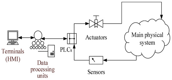
Figure 1.
A sketch of the main components of an I&C system.
Let emphasize that CPS development heightens concerns about system trustworthiness, usability which include security, privacy, safety, reliability, resilience, and efficiency [13].
The CPS reliability is conditioned by both the reliability of physical components and software modules’ reliability. The reliability assessment problem for physical objects is well-developed, while the reliability estimation for software systems is still an unsolved issue. For example, Antonov et al. [14] performed an overview of software reliability estimation quantitative methods and concluded that current numerical methods do not provide credible estimations of reliability in a classical probability domain. That’s why the term of software reliability is widely substituted by the term of software quality which, according to the standard ISO/IEC 25010:2011 [15], is “the degree to which a product or system can be used by specific users to meet their needs to achieve specific goals with effectiveness, efficiency, freedom from risk and satisfaction in specific contexts of use.” ISO/IEC standards introduce some metrics to estimate different software quality factors, so by their values, it might be possible to draw indirect conclusions about the reliability of specific software under a set of specific conditions.
That is why the software reliability estimation is usually performed by testing the software in conditions as close as possible to the operation’s conditions. The test cases should cover both normal and stress scenarios of software functioning.
The software quality assurance process has its difficulties:
- the absence of a real control object or its components for a sufficiently long time (sometimes up to the final stage of development);
- the impossibility (for example, because of risk of physical destruction or high costs) of tests in some operating modes.
Modeling at the earliest possible stages of software development increases testing capability for the real system and reduces the costs and time of achieving the required software quality. It allows checking both separate system components and the entire architecture of the designed system.
3. Comparison of Model Types Regarding Cyberphysical Systems
Simulation is an integral part of the design and development of any industrial system. It helps to understand and predict a physical object’s behavior and the properties of control algorithms; assess system reliability and safety and fault tolerance; know how the system will react to control; divide the system into functional modules; design the data structure and communication channels and so on. All of these problems are addressed using various models. Table 1 shows a comparison of different models and an assessment of their potential for use for a physical or digital component (“+” or “−” signs indicate whether the model is suitable for a specific purpose or not).

Table 1.
Comparison of the properties of the models.
Full-scale test prototypes can be built to test and verify the interaction of system elements. There is a preliminary fitting to the real equipment; the final integration with the physical object is carried out during the commissioning stage. In the first place, the work requires time, labor and cost, because designing and building a full-scale prototype requires a lot of resources, and such tests reveal errors and inconsistencies in the last stages of system development. Correcting inconsistencies requires hard work to retest the system.
With the progress of the computational facilities, the concept of digital twins of cyberphysical systems has been gaining popularity. The digital twin runs in a purely virtual, computer environment. It receives the information about the physical object either from a simulation or from a real object data via the Internet of Things.
4. Restrictions and Application of Digital Models of Cyberphysical Systems
With the virtual models of cyberphysical systems, one can configure the system and test the interaction between system components and system modes at any development stage. There are numerous successful applications of the digital twin for different systems and purposes.
For example, Lemay et al. [18], using a number of virtual machines running within a computational cluster, created a digital training model for a SCADA (supervisory control and data acquisition) system of a reference power plant. They used some simulations of physical processes and PLCs, sensors, and actuators. The model allowed to imitate a set of cyberattacks to a reference SCADA system, albeit not showed high productivity.
Alves et al. [19] for cybersecurity protective measures tests applied modularity principles to the design and construction of a digital model of a SCADA system. They implemented every SCADA element (server, workstation, PLC, sensor, et cetera) as a separate software module that allows model scaling in a wide range.
This way the design and deployment of digital twins of cyberphysical systems is an essential and expanding technology. However, it is necessary to understand and take into account the boundaries of digital models. Let us discuss some use cases for the digital twin and draw out the possible limitations and ways to mitigate the limitations.
First, with a digital model, one hardly (if ever) can obtain any data about the real system’s productivity. The system productivity depends on specific models of installed computers and controllers, network capacity, and many other conditions. A virtual model allows getting just some productivity estimates like algorithm performance.
Second, any specific manufacturer’s hardware and equipment have their features and restrictions; some internal details of equipment functioning are proprietary information and trade secrets, so they cannot be implemented entirely in a virtual model. It means the virtual model will use some “average,” “neutral” models of the equipment, which also will not allow getting an accurate model.
Timing is a central architectural concern of a CPS [13], so it is essential to guarantee a transparent mapping of the dynamics of a real cyberphysical system and the digital model. Lee and Seshia [20], in chapter 1 of their book, describe the problem in detail.
The time-dependent dynamic properties of physical objects are usually described by systems of differential equations (equations of motion, equations of heat conduction, equation of electrodynamics), where time is a variable. Thus, a physical object’s digital model is a solution to a system of differential equations describing its behavior. The process of solving math problems usually does not require real-time computation. The model’s digital component can receive the results of calculations performed in advance, and the virtual model will approximate them.
Digital twins usually implement software models of sensors and controllers: they can use either software emulation (many manufacturers provide emulators) of software models of state machines or black boxes. Note that a program thread’s CPU time is not real physical time because a computer represents a time stream by incrementing a hardware-dependent counter. Thus, the device digital model’s temporal properties may differ from the properties of the real device. We summarize these considerations in Table 2.
Table 2.
The principles of CPS digital twin design.
Maintaining a uniform timeline is essential for I&C systems. On the other hand, cloud systems with many virtual machines have multiple context switching events between processes inside the computer and between virtual machines inside the host. This raises another important problem—the problem of synchronizing components in the digital model. Currently, the issue of synchronizing the system of virtual machines has not been studied in detail, but the problem is recognized. Thus, VMware [21] says that differences between virtual and real machines “can still sometimes cause timekeeping inaccuracies and other problems in software running in a virtual machine.” Therefore, there is always a risk that the necessary synchronization accuracy would never be achieved in the digital model of the CPS.
One of the promising functions of digital twins is developing cyber defense methods and testing the system’s resistance to cyber threats. Here cybersecurity is a set of actions and measures (controls) to prevent, detect and respond to malicious actions against the system. Indeed, a digital twin makes it possible to carry out any tests without risk of real system damaging, and it is easy enough to return a digital model to its original state even after the destruction of the digital twin because of a cyberattack. Some elements of a physical infrastructure could become an attack starting point (for example, an intruder gets physical access to a server); the attack goal could be reducing the system availability as in case of a denial-of-service attack (DoS-attack).
Considerations of the previous paragraph show that digital twins can be used to find the vulnerability points in a cyberphysical system, divide the system into the cybersecurity levels, investigate cyberattack propagation paths, and estimate the attack consequences. However, they are not suitable for researching cyberattacks’ temporal characteristic and studying the cyberattacks on the physical infrastructure (physical access to servers, bridges, et cetera).
The limitations described above can be partially removed for a model in which virtual components interact with some real parts. For example, you can include several real sensors and PLCs in the model. The sensors will transmit their output to the virtual environment; the physical process model will compute the inputs to the PLC and transfer the signals to the standard PLC interfaces. This kind of partial integration will allow us to check the timing of some control signals and simplify the commissioning process.
The principle of combining real and model components in modeling is known as Hardware-in-the-Loop simulation. In our opinion, there is a consensus in the industry (see, for example, papers [22,23]) when HiL simulation uses a computer as a virtual representation of the object model and real controllers or field devices. So, HiL usually is related to Levels 0–1 (Production Process, Sensing and Actuation) of IEC 62264-3 standard [24]. There are two specific features of the proposed digital twin approach. The first one that an I&C system spans across levels 1–3 (Sensing and Actuation; Monitoring, Supervision and Control; Manufacturing Operations and Control) and the digital twin may include real components at all levels. The second one that real components are not only hardware but else software modules.
To highlight this feature, this configuration of the digital twin is called a heterogeneous digital twin in the framework of this work. A heterogeneous digital model can facilitate the process of integrating components into a single system because the complexity and labor intensity of creating and maintaining/updating a heterogeneous virtual model is much less than that of a full-scale test complex.
The scenarios of digital twin applications also depend on the modeled system’s lifecycle stage. Table 3 shows the possible scenarios depending on the lifecycle stage.
Table 3.
The I&C lifecycle stages and corresponding scenarios of using the digital twin.
5. Digital Twin Architecture and Configuration Management
So far, we have not considered the hierarchical structure of an I&C system, its lifecycle, and the problem of the synchronization keeping between a digital twin and the real object. A digital twin developer should consider that the digital twin will co-evolve with the real I&C system during the lifecycle from a very high-level abstract representation to a very detailed representation. Moreover, almost all real systems have subsystems, and the subsystems, in turn, include further subdivisions, etc. The system requirements usually follow the hierarchical structure of the system itself. To consider the digital twin requirements of a hierarchical system, it is necessary to coordinate the requirements between different architecture levels of the twin.
Let us illustrate this reasoning with an example of a system having one nesting level. In the case of hierarchical systems with more levels, we may use an inductive approach.
The subsystems’ structure is not developed yet at the early design stage, but the set of subsystems is identified, and the relations between them are already known. One can present the system as a graph with components as vertices and with edges representing the binary relation of directed dependence between components in the system operation frame. The subsystem has some assigned properties.
The developers of a digital twin face some questions. Suppose a property is assigned to the subsystem, and during the system development, the subsystem developers implement the property in a specific way. Then, how do we make the digital twin co-evolve correctly with the system prototype?
Let us consider two graphs. The left one, , takes into consideration the structure of subsystems, and the second one, , describes the high-level abstraction or top-level system structure (see Figure 2). must be evidently a result of graph contraction : that is not a one-to-one mapping.
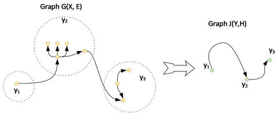
Figure 2.
Graphs of I&C information model with subsystem hierarchy (left) and without it (right).
The problem solution becomes simple if the digital twin is initially designed as a system of nested containers. Every container serves as a framework for lower-level components and puts some additional constraint from upper-level requirements onto the container elements.
The second problem we need to pay special attention to is synchronization between the digital twin and the real I&C system and the configuration management. Indeed, the digital twin designer must maintain the equivalence between the digital model and the real I&C system (see Figure 3). However, below (see Section 6), it will be shown that the full equivalence might be unachievable in practice. Nevertheless, two co-evolving systems must synchronize their configurations for the equivalent sets.
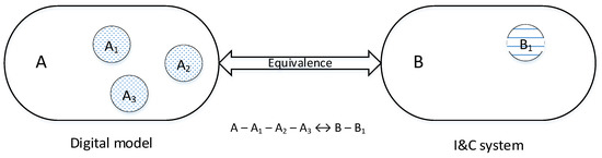
Figure 3.
The equivalence of the I&C systems and its digital model. The part of the I&C system that is not covered with the model is shown as a set B1; the model components that have not counterparts in the real system are shown as sets A1, A2, A3.
Let us say a few words about our understanding of the equivalent configurations. Software Engineering Body of Knowledge (SWEBOK) [25] defines configuration as “a collection of specific versions of hardware, firmware, or software items combined according to specific build procedures to serve a particular purpose.” We will simplify this definition for the modeling and say that configuration is a set of backbone components (hardware and software) currently installed in the system. It means that some key components must be identified at the model design stage, and the synchronization procedure for the maintenance of the equivalence of those key components must be implemented over the lifecycle stages.
For example, if the CPU model is supposed to be the configuration element, then the digital twin must emulate the same CPU which is used in the real I&C system. On the other hand, a model designer may consider the difference of two executable programs insignificant and take into account only the differences in configuration files of these programs. Below, we will show an example of a configuration description for a real use case.
6. The Realization of the Composite Heterogeneous Digital Twin for Instrumentation and Control System of the Nuclear Power Plant
Basing on the proposed approach of the heterogeneous digital twin, we designed and built a heterogeneous digital model of the upper-level control system (ULCS) of the I&C system of a nuclear power plant [11]. The ULCS offers the integration functionality for various parts of the I&C system and ensures the interaction of all other systems of the I&C NPP system. The ULCS represents a modern digital networked distributed control system. The main functions of the ULCS are monitoring and control of the NPP state. The functions include safety-related functions and auxiliary functions; the last are self-diagnostic, archiving plant-state data in the database, and providing time synchronization for other components of the I&C system. The ULCS system provides the human–machine interface with the plant equipment and contains about thirty workstations in a typical configuration. An essential characteristic of the system is its functioning in real-time while providing a human-machine interface with a human operator. To increase the systems’ reliability, design measures have been taken to provide the system redundancy (communication lines and computing nodes are backed up).
The system has a modular architecture that allows increasing the number of operator’s workplaces and processed information. In a basic configuration for NPP, the total volume of the managed database is about 106 signals, with a performance of about several thousand signals per second.
The ULCS consists (see Figure 4) of servers, active and passive network equipment, workstations, auxiliary equipment of the cabinets (uninterruptible power sources, printers, et cetera). The information is transferred over Ethernet networks; all key nodes and data paths are redundant and work in parallel, providing hot-spare redundancy. The ULCP software works under the industrial Linux-based operating system LICS OS [26]. Precise time sources provide a unified time scale within the system.
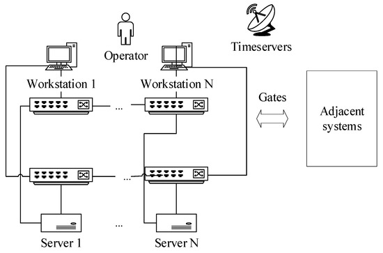
Figure 4.
The outline of the upper-level control system of an NPP ULCS.
The ULCS digital twin is a kind of a composite digital twin that combines several small (discrete) digital twins of the equipment and software of the ULCS. The digital twin combines the computational, analytic models and hardware components and allows to describe, diagnose, predict and simulate the states and behaviors of the ULCS.
The ULCS digital twin receives data from the supplementary software-based digital twins of the adjacent systems of the NPP. The supplementary digital twins include both model-based sources of the data and some previously recorded data from the real equipment dynamics.
The auxiliary digital twins are used to simulate plant dynamics for normal and some abnormal modes of the NPP operation, to predict and simulate the states and behavior of the real ULCS depending on the plant data.
6.1. The Architecture of the ULCS Digital Twin
The ULCS digital twin includes some elements of the ULCS system’s real hardware and about a hundred virtual components representing ULCS computers and network devices (see Figure 5).
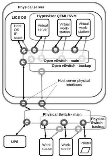
Figure 5.
The outline of the heterogeneous digital model of the ULCS.
The real hardware comprises a timeserver, a switch cabinet, a workstation cabinet with an operator terminal, server cabinet.
A real timeserver acts as the time synchronization source via the Network Time Protocol (NTP). Switch cabinet and server cabinet hardware elements are used to model the behavior of server and workstation system units in the cabinet (for example, uninterruptible power supply (UPS) control and monitoring). The workstation cabinet is identical to the real operator’s terminal.
The virtual machines for every server and workstation physically run on a host server under LICS OS and QEMU/KVM hypervisor [27,28]. The workstation physical computer runs under LICS OS as well. The specifications of real and virtual components are summarized in Table 4 and Table 5.
Table 4.
Real computer parameters.
Table 5.
Parameters of virtual components.
The ULCS network-related properties simulation is an important part of the digital twin realization because the ULCS is a distributed network control system.
The ULCS components interact with each other using TCP/IP and UDP/IP protocols. As we discussed earlier, operational servers, workstations, and Ethernet networks are redundant, and the model must reflect both logical and physical redundancy of the system. Since the model is heterogeneous, it is assumed to interact with the real hardware and software components via the network. The structure of the digital twin network is equivalent to the structure of the ULCS network. Most of the network-related elements in the digital twin are built on virtual components. Virtual switch software OpenVSwitch [31] is a tool for network topology construction within the model. Thereby, every real switch is mapped to a virtual switch, and the commutation of virtual machines and virtual switches within the virtual network corresponds to the ULCS network topology. VLAN assignment within software switches allows modeling the physical separation of redundant Ethernet channels. Thus, we model network redundancy where any single failure in the network path does not break the system connectivity.
To provide the connection between virtual machines and real equipment, the host OS network stack is connected to the virtual switches so that the virtual machines can access the external hardware via a real Ethernet network.
Figure 6 and Figure 7 present an illustration of the described approach. Suppose we have a server S1 belonging to one subsystem and two other computers, server S2 and workstation W, belonging to another subsystem. All network traffic goes via two independent and physically separated Ethernet networks named as main network and standby network. Every subsystem also has its own set of Ethernet switches containing at least two devices: one for the main network, the other for the standby network. Here in the figure, the boxes SM1 and SM2 are the switches for the main network, the boxes SS1 and SS2 are the switches for the standby network. The network traffic between the I&C system components passes via Ethernet lines between the switches (bold lines on Figure 4).
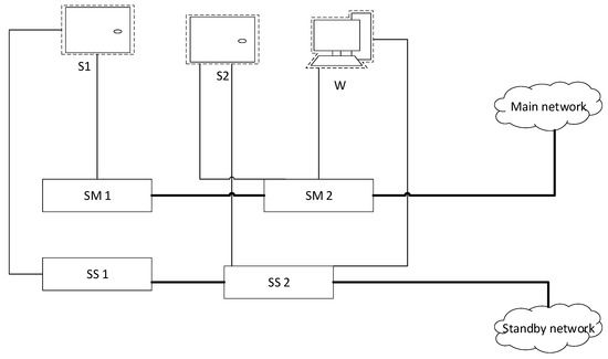
Figure 6.
A fragment of the real ULCS network topology.
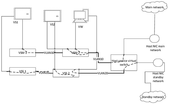
Figure 7.
A fragment of the digital twin network topology.
Now let us show the implementation of the presented topology within the digital model. Virtual machines VS1, VS2, VW correspond to the real machines S1, S2, W, virtual switches VSM1, VSM2, VSS1, and VSS2 implemented as OpenVSwitch instances correspond to the hardware Ethernet switches SM1, SM2, SS1, and SS2, respectively. The switches of the main network are linked via trunk ports with the tag “VLAN10”, the switches of the standby network are linked via trunk ports with the tag “VLAN20”.
The traffic to access ports (ports leading to terminal devices like a server or a workstation) of the virtual switches is tagged with the corresponding VLAN label (VLAN10 or VLAN20). This is the way we model the physical separation of two Ethernet networks.
To allow model interaction with external hardware (for example, with a real workstation), we created an auxiliary virtual switch instance in the host server. This instance is linked with the model’s main network via trunk port with the tag “VLAN10” and the standby model network via trunk port with the tag “VLAN20”. The real host Ethernet adapters are connected with the corresponding access ports of the auxiliary virtual switch (port tagged “VLAN10” for the main network, port tagged “VLAN20” for the standby network.
The virtual machines and the real hardware communicate via TCP/IP and UDP/IP network protocols like SNMP (Simple Network Management Protocol) through real Ethernet networks. To work with the operator graphical environment, we pass the graphics via Spice network protocol [32] to the real workstation. The Spice client software was also installed onto the virtual machines.
6.2. The Data Synchronization between the Digital Twin and the Real ULCS
To facilitate the configuration management process, during the digital twin design and implementation we developed a structure of configuration description. Configuration structure is based on the approach of the system of nested containers. The digital twin configuration is the set of its components’ configurations (for example, servers and workstations). The configuration of every component may be unfolded further, generating a configuration tree. An example of UML (unified modelling language) diagram representing a configuration tree node is shown below in Figure 8.
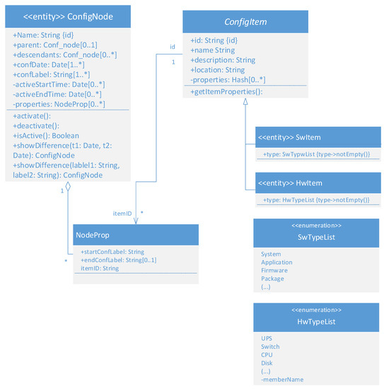
Figure 8.
Example of UML representation of configuration node for a digital twin.
The developed structure is backed by a bi-directional synchronization technique built upon ansible [30] software. It allows solving the problems of identical configuration maintenance in the digital twin and the real ULCS, digital twin cloning in a cloud-based environment, software deployment preparation.
However, the model operation process showed some peculiarities in the heterogeneous model design that result from the not full equivalence of a digital twin and the real object.
For example, in the beginning, the computer hardware emulated by the hypervisor (like controllers, network adapters) was chosen to be maximally close to the real one. However, the performance of software emulation of the devices did not satisfy the needs of the I&C system, and the model showed poor network throughput. So, we had to switch over to paravirtual devices (for the description of software emulated and paravirtual devices see, e.g., papers [33,34]) and give up the idea of maximal similarity between the emulated and real hardware.
6.3. The Timekeeping in the Digital Twin
Virtualization is a key technology used in the presented ULCS digital twin. We encountered some difficulties in the provision of a timekeeping mechanism between the components of the digital twin.
The real I&C system uses NTP protocol [35] for the timekeeping, so the digital twin follows this approach. We found few research papers and guides for timekeeping in the virtual environment, and they only give general advice without real use-case analysis (see, for example, [21] and [36]).
The implementation of recommended settings [37] brought a problem. Under low load, the system after the initial synchronization period stays in the synchronized state, but under heavy load, clock offsets vary within a large interval that, in our case, achieves up to hundreds of milliseconds (see the left picture in Figure 9). The offset increases, achieves a threshold value, and then, according to the NTP protocol specification, is set to zero forcibly. The analysis of the problem led us to the task of clock driver choice.
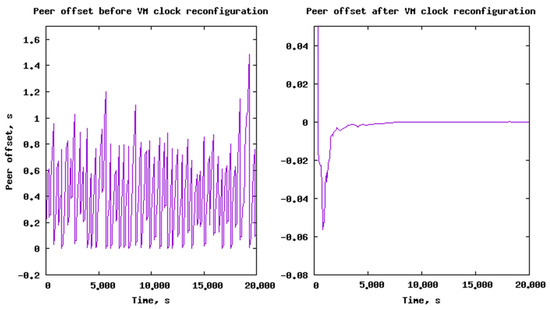
Figure 9.
(Left): NTP offset between the local system clock and the timeserver clock before the system clock reconfiguration. (Right): NTP offset between the local system clock and the timeserver clock after the system clock reconfiguration.
Note that the time offset on the left part of Figure 9 is non-negative. It means the virtual machine system clock keeps behind the timeserver clock. In that case, we used the paravirtual clock driver “kvm-clock”, the default clock driver for QEMU/KVM hypervisor. We suppose that simultaneously working virtual machines block one to another the access to the hypervisor clock and skip the required interrupts. In our opinion, the usage of the paravirtual clock driver in this case created a bottleneck.
So, we switched to another clock driver, emulated TSC (time step counter) clock. This is an evenly increased processor register, a counter of CPU cycles. It is stable for modern CPUs, does not depend on the CPU frequency’s dynamical changes, and is even unified within a multiprocessor system. After the reconfiguration of virtual machines, we managed to achieve the required time synchronization accuracy.
7. Results and Discussion
The design and accurate realization of a digital twin remains a challenging task. In the paper, we consider instrumentation and control systems (I&C systems) as cyberphysical systems (CPS) of the Industry 4.0 concept and, in particular, deal with the problem of the design of digital twins of CPS in application to I&C systems. The proposed heterogeneous digital twin can facilitate accurate reproduction of the real I&C system properties. The main advantages are the precise reproduction of time dynamics and interaction, the behavior of auxiliary devices, and network topology. We propose a heterogeneous digital twin concept for an I&C system of levels 1–3 of IEC 62264-3 standard [22] (Sensing and Actuation; Monitoring, Supervision and Control; Manufacturing Operations and Control). The heterogeneous twin is similar to the hardware-in-the-loop digital twins. It consolidates software and hardware components of different system levels and combines specific analytical software components of digital twin and the real software of the simulated system. Compared with purely analytical models and full-scale testbeds, this type of digital twins extends the list of their applications at various lifecycle stages.
Incidentally, the heterogeneous digital twins have fewer hardware units than the full-scale testbeds, without the loss of accuracy in the modeling of system dynamical characteristics. On the other hand, compared with a pure software model, the model accuracy is better by incorporating real components.
System cybersecurity assessment is a relatively new scenario of digital twin applications. Digital twins of I&C systems can be used to identify vulnerability points, divide the system into cybersecurity levels, investigate the propagation paths of attacks, and assess the consequences of cyber-attacks.
The realization and application of a digital twin allow decreasing software quality assurance costs because the digital twin is more available for the tests in various modes. We got the successful practice of digital twin application for quality assurance. The experience is based on the fact that a digital twin, being in many cases a rough copy of a real object, changes test coverage in comparison to the real object. Particularly, it appears in the fact that some of the errors that would most likely remain undetected during normal testing on a real object are detected on a digital twin. Moreover, it is possible to clone more the digital twin entity more than once and increase test coverage in this way.
We have demonstrated the heterogeneous digital model’s effectiveness in the course of the development of the upper-level control system (ULCS) for a nuclear power plant. The ULCS composite digital twin includes about one hundred virtual and real items (servers, workstations, network equipment) and fully reproduces the real system properties, including the redundancy in components and networks. The ULCS digital twin is used to validate the system deployment during the commissioning, measure and analyze performance characteristics of the ULCS, test some special modes that may be hard to conduct on the real system due to cost or safety restrictions, and correct associated errors. Our experience shows that the percent of errors related to the special modes is about 15%–20% from all software errors detected at late software quality assurance stages.
In practice we conclude that a heterogeneous digital twin only reduces but not eliminates the modeling approach restrictions since it is difficult to achieve the complete equivalence between a digital twin and the simulated system. The weak points of the heterogeneous digital twin still are: graphical mode and HMI productivity in a virtual environment, timekeeping issues, differences in general network throughput in virtual and real components, and difficulties in achieving operational relevance between the digital twin and the modeled real object in the presence of bugs and errors. This should be taken into account when organizing the digital twin’s synchronization and the real system and correlating the data obtained from the digital twin and the real object.
This work is the result of the creation of the ULCS NPP digital twin and its application at the stage of development and deployment of a real system. We plan to continue working with the digital twin at other stages of the ULCS lifecycle. The main focus will be on improving the synchronization mechanisms of the digital twin and the real system, increasing the accuracy of the models, first of all, in dynamical and temporal characteristics, and the development of techniques that allow diagnostics and prognostics of the behavior of a real system on a digital twin.
Author Contributions
Conceptualization and digital twin architecture, A.P.; methodology, A.P. and N.M.; technical implementation support, N.M. and V.P.; software interfaces and configuration management system, K.S.; validation scenarios development and formal analysis, V.P.; investigation, V.P., K.S., and N.M.; writing—original draft preparation, K.S. and N.M.; writing—review and editing, V.P. and A.P. All authors have read and agreed to the published version of the manuscript.
Funding
Acknowledgments
We are grateful to A. S. Shumov and I. U. Sakhabetdinov for the technical assistance.
Conflicts of Interest
The authors declare no conflict of interest.
References
- Kagermann, H.; Lukas, W.-D.; Wahlster, W. Industrie 4.0: Mit dem Internet der Dinge auf dem Weg zur 4. industriellen Revolution. VDI Nachr. 2011, 13, 2–3. [Google Scholar]
- Hermann, M.; Pentek, T.; Otto, B. Design Principles for Industrie 4.0 Scenarios: A Literature Review. In Proceedings of the 2016 49th Hawaii International Conference on System Sciences (HICSS), Koloa, HI, USA, 5–8 January 2016; Available online: https://www.researchgate.net/publication/307864150_Design_Principles_for_Industrie_40_Scenarios_A_Literature_Review (accessed on 27 January 2021). [CrossRef]
- Kagermann, H.; Wahlster, W.; Helbig, J. Recommendations for Implementing the Strategic Initiative Industrie 4.0: Securing the Future of German Manufacturing Industry; final report of the Industrie 4.0 working group; Forschungsunion: Berlin, Germany, 2013; pp. 1–79. [Google Scholar]
- Schumacher, A.; Erol, S.; Sihn, W. A maturity model for assessing Industry 4.0 readiness and maturity of manufacturing enterprises. Procedia CIRP 2016, 52, 161–166. [Google Scholar] [CrossRef]
- Zhong, R.Y.; Xu, X.; Klotz, E.; Newman, S.T. Intelligent Manufacturing in the Context of Industry 4.0: A Review. Engineering 2017, 3, 616–630. [Google Scholar] [CrossRef]
- Stanford-Clark, H.; Frank-Schultz, E.; Harris, M. What Are Digital Twins? 2019. Available online: https://developer.ibm.com/technologies/iot/articles/what-are-digital-twins/ (accessed on 25 February 2021).
- Industrial Internet Consortium. Digital Twins for Industrial Applications. Definitions, Business Values, Design Aspects, Standards and Use Cases; An Industrial Internet Consortium White Paper, v. 1.0. 2020. Available online: https://www.iiconsortium.org/pdf/IIC_Digital_Twins_Industrial_Apps_White_Paper_2020-02-18.pdf (accessed on 25 February 2021).
- W3C. Web of Things (WoT) Architecture. W3C Recommendation 9 April 2020. Available online: https://www.w3.org/TR/2020/REC-wot-architecture-20200409/ (accessed on 25 February 2021).
- Tao, F.; Zhang, M.; Liu, Y.; Nee, A.Y.C. Digital twin driven prognostics and health management for complex equipment. CIRP Ann. Manuf. Technol. 2018, 67, 169–172. [Google Scholar] [CrossRef]
- Poletykin, A.; Jharko, E.; Mentgazetdinov, N.; Promyslov, V. The new generation of upper levels systems and industry 4.0 conception in NPP APCS. In Proceedings of the 10th International Conference of Management of Large-Scale System Development, Moscow, Russia, 2–4 October 2017; pp. 1–5. [Google Scholar] [CrossRef]
- Byvaikov, M.E.; Zharko, E.F.; Mengazetdinov, N.E.; Poletykin, A.G.; Prangishvili, I.V.; Promyslov, V.G. Experience from design and application of the top-level system of the process control system of nuclear power-plant. Automat. Rem. Contr. 2006, 67, 735–747. [Google Scholar] [CrossRef]
- Semenkov, K.; Promyslov, V.; Poletykin, A.; Mengazetdinov, N. Verification of Large Scale Control Systems with Hybrid Digital Models and Digital Twins. In Proceedings of the 2020 International Russian Automation Conference (RusAutoCon), Sochi, Russia, 6–12 September 2020; pp. 325–329. [Google Scholar] [CrossRef]
- NIST Cyber Physical Systems Public Working Group. Framework for Cyber-Physical Systems, Release 1.0, May 2016. Available online: https://s3.amazonaws.com/nist-sgcps/cpspwg/files/pwgglobal/CPS_PWG_Framework_for_Cyber_Physical_Systems_Release_1_0Final.pdf (accessed on 25 February 2021).
- Antonov, A.V.; Zharko, E.F.; Promyslov, V.G. Problems of Evaluation of Software Dependability and Quality in Industrial Automation and Control Systems. Dependability 2015, 4, 87–96. Available online: https://www.dependability.ru/jour/article/download/107/288 (accessed on 13 March 2021). [CrossRef]
- ISO/IEC. Standard “Systems and Software Engineering–Systems and Software Quality Requirements and Evaluation (SQuaRE)–System and Software Quality Models”; International Organization for Standardization: Geneva, Switzerland, 2011. [Google Scholar]
- Baybulatov, A.A.; Promyslov, V.G. Control System Availability Assessment via Maximum Delay Calculation. In Proceedings of the 2019 International Conference on Industrial Engineering, Applications and Manufacturing (ICIEAM-2019), Sochi, Russia, 25–29 March 2019; pp. 1–6. [Google Scholar] [CrossRef]
- Schütze, M.; Bondorf, S.; Kreider, M. Verification of the FAIR Control System Using Deterministic Network Calculus. In Proceedings of the 16th International Conference on Accelerator and Large Experimental Control Systems (ICALEPCS 2017), Barcelona, Spain, 8–13 October 2017; Costa, I., Fernández, D., Matilla, Ó., Schaa, V.R.W., Eds.; JACoW: Geneva, Switzerland, 2018; pp. 238–245. [Google Scholar] [CrossRef]
- Lemay, A.; Fernandez, J.; Knight, S. An isolated virtual cluster for SCADA network security research. In Proceedings of the First International Symposium for ICS & SCADA Cyber Security (ICS-CSR 2013), Leicester, UK, 16–17 September 2013; BSC Learning & Development Ltd.: Swindon, UK, 2013; pp. 88–96. [Google Scholar]
- Alves, T.; Das, R.; Werth, A.; Morris, T. Virtualization of SCADA testbeds for cybersecurity research: A modular approach. Comput. Secur. 2018, 77, 531–546. [Google Scholar] [CrossRef]
- Lee, E.A.; Seshia, S. Introduction to Embedded Systems–A Cyber Physical Systems Approach, 2nd ed.; MIT Press: Cambridge, MA, USA, 2017. [Google Scholar]
- Timekeeping in VMware Virtual Machines. Available online: https://www.vmware.com/content/dam/digitalmarketing/vmware/en/pdf/techpaper/Timekeeping-In-VirtualMachines.pdf (accessed on 27 January 2021).
- National Instruments. What Is Hardware-In-The-Loop? White Paper, Updated 17 December 2020. Available online: https://www.ni.com/en-us/innovations/white-papers/17/what-is-hardware-in-the-loop-.html (accessed on 25 February 2021).
- Mathworks. What Is Hardware-In-The-Loop Simulation? Mathlab Documentation. Available online: https://www.mathworks.com/help/physmod/simscape/ug/what-is-hardware-in-the-loop-simulation.html (accessed on 25 February 2021).
- IEC. IEC Standard 62264-3:2016. Enterprise-Control System Integration—Part 3: Activity Models of Manufacturing Operations Management; International Organization for Standardization: Geneva, Switzerland, 2016. [Google Scholar]
- ISO/IEC. ISO/IEC TR 19759:2015 Software Engineering—Guide to the Software Engineering Body of Knowledge (SWEBOK), 2nd ed.; International Organization for Standardization: Geneva, Switzerland, 2016; 336p. [Google Scholar]
- LICS Registration Certificate. 2019. Available online: https://www1.fips.ru/publication-web/publications/document?type=doc&tab=PrEVM&id=07B0B75D-B08F-4A7B-BF76-011ED855B976 (accessed on 27 January 2021).
- KVM Documentation. Available online: https://www.linux-kvm.org/page/Documents (accessed on 27 January 2021).
- QEMU Documentation. Available online: https://wiki.qemu.org/Main_Page (accessed on 27 January 2021).
- Libvirt: Virtualization API. Available online: https://libvirt.org/ (accessed on 27 January 2021).
- RedHat Ansible. Available online: https://www.ansible.com/ (accessed on 27 January 2021).
- OpenVSwitch. Available online: https://www.openvswitch.org/ (accessed on 27 January 2021).
- Spice Protocol. Available online: https://www.spice-space.org/ (accessed on 27 January 2021).
- Semenkov, K.V.; Mengazetdinov, N.E.; Poletykin, A.G. Extending Operation Lifespan of Instrumentation and Control Systems with Virtualization Technologies. In Proceedings of the 2019 International Russian Automation Conference (RusAutoCon 2019), Sochi, Russia, 8–14 September 2019; pp. 1–5. [Google Scholar] [CrossRef]
- Goto, Y. Kernel-based Virtual Machine Technology. FUJITSU Sci. Tech. J. 2011, 47, 362–368. [Google Scholar]
- Mills, D. Computer Network Time Synchronization. The Network Time Protocol on Earth and in Space, 2nd ed.; CRC Press: Boca Raton, FL, USA, 2011. [Google Scholar]
- Burnicki, M. Time Synchronization in Virtual Machines. Available online: https://kb.meinbergglobal.com/kb/time_sync/time_synchronization_in_virtual_machines (accessed on 27 January 2021).
- KVM Guest Timing Management. Available online: https://access.redhat.com/documentation/en-us/red_hat_enterprise_linux/7/html/virtualization_deployment_and_administration_guide/chap-kvm_guest_timing_management (accessed on 27 January 2021).
Publisher’s Note: MDPI stays neutral with regard to jurisdictional claims in published maps and institutional affiliations. |
© 2021 by the authors. Licensee MDPI, Basel, Switzerland. This article is an open access article distributed under the terms and conditions of the Creative Commons Attribution (CC BY) license (http://creativecommons.org/licenses/by/4.0/).