1. Introduction
Full-electric vehicles (EVs) are increasingly attracting attention as they promise to offer advantages over traditional internal combustion engine vehicles in terms of environmental impact and improved efficiency [
1]. However, some issues need to be addressed before a widespread diffusion of EVs can be achieved. One of the main challenges refers to the limited autonomy that can be obtained through the development of efficient transmission systems and their integration with existing EV powertrains. Electric motors can be directly connected to the drive wheels of EVs, or a transmission system can be placed between the motor and the wheels to optimize the vehicle performance [
2]. Currently, manufacturers tend to adopt single-speed transmission systems, as they ensure minimization of the cost, volume, energy loss, and drivetrain mass. However, with a fixed ratio transmission system, EV powertrain performance significantly depends on the performance of the traction motor, which is not equally efficient in all speed ranges [
3,
4,
5]. The further an electric motor moves from the nominal operating point, the higher the efficiency drop. This results in a significant energy consumption during cycles with highly changing conditions (e.g., urban driving cycles [
6]).
Recent advances in power electronics for drive motors have made available new motion controllers that allow more complex algorithms and architectures to be adopted in the pursuit of improved energy efficiency for electric vehicles [
7]. In previous research [
8,
9], the energy efficiency over a given standard driving cycle was characterized against a few representative points, and the design optimization was performed with respect to these points. Similarly, in [
10], a procedure was proposed to evaluate the most effective design areas by means of a series of representative points taken from the map of a permanent-magnet-assisted synchronous reluctance motor, which have been considered for the global optimization.
Propulsion systems that use a series of gearless electrical continuously variable transmissions (E-CVT) were presented in [
11]. A differential evolution algorithm was used in conjunction with the finite element method to gain optimal torque and energy efficiency, and to reduce, at the same time, the torque ripples of the E-CVT.
Other optimization approaches can be found in [
12], where the design of an induction motor was studied by applying a genetic algorithm. An evolutionary optimization procedure was proposed in [
13] for drive motors of electric vehicles that adopts an adaptive differential evolution algorithm involving dynamic variation of the mutation factor that is combined with finite-element (FE) and circuit models.
Various attempts have been discussed to introduce novel architectures of power transmissions that allow the working range of an electric motor to be kept in the vicinity of its point of best efficiency [
14], including the use of continuous variable transmission [
15] also in combination with a series spring system [
16]. A system with an infinitely variable transmission has been also proposed in [
17] to maximize the efficiency of an electric motor.
With the goal of maximizing the energy stored by a wind system, a planetary gear solution was proposed in [
18], by investigating the analytical relationship that maps the torque with the speed of the wind turbine. The use of a planetary gear also allows the power of two motors to be combined to reduce transmission nonlinearities [
19]. Finally, in [
20], a strategy was developed to adaptively split the load between two sources for an electric vehicle adopting a hybrid energy storage system that can effectively reduce the battery power stress.
In this paper, we propose a powertrain solution for EVs that includes two electric motors and a planetary gear, which allows the load to be distributed between the two motors. The aim is to increase the energy efficiency of the vehicle, by optimizing the combined speeds of two motors. Such a solution is possible thanks to the additional degree of freedom provided by the planetary combiner. The control strategy for the power distribution of energy between the motors is a decisive factor in the minimization of power losses of the propulsion system. The proposed power split control strategy has the capacity to achieve vehicle speeds either working only with one electric motor (relying on a brake system) and working with two electric motors at the same speed, or working with two electric motors at different speeds.
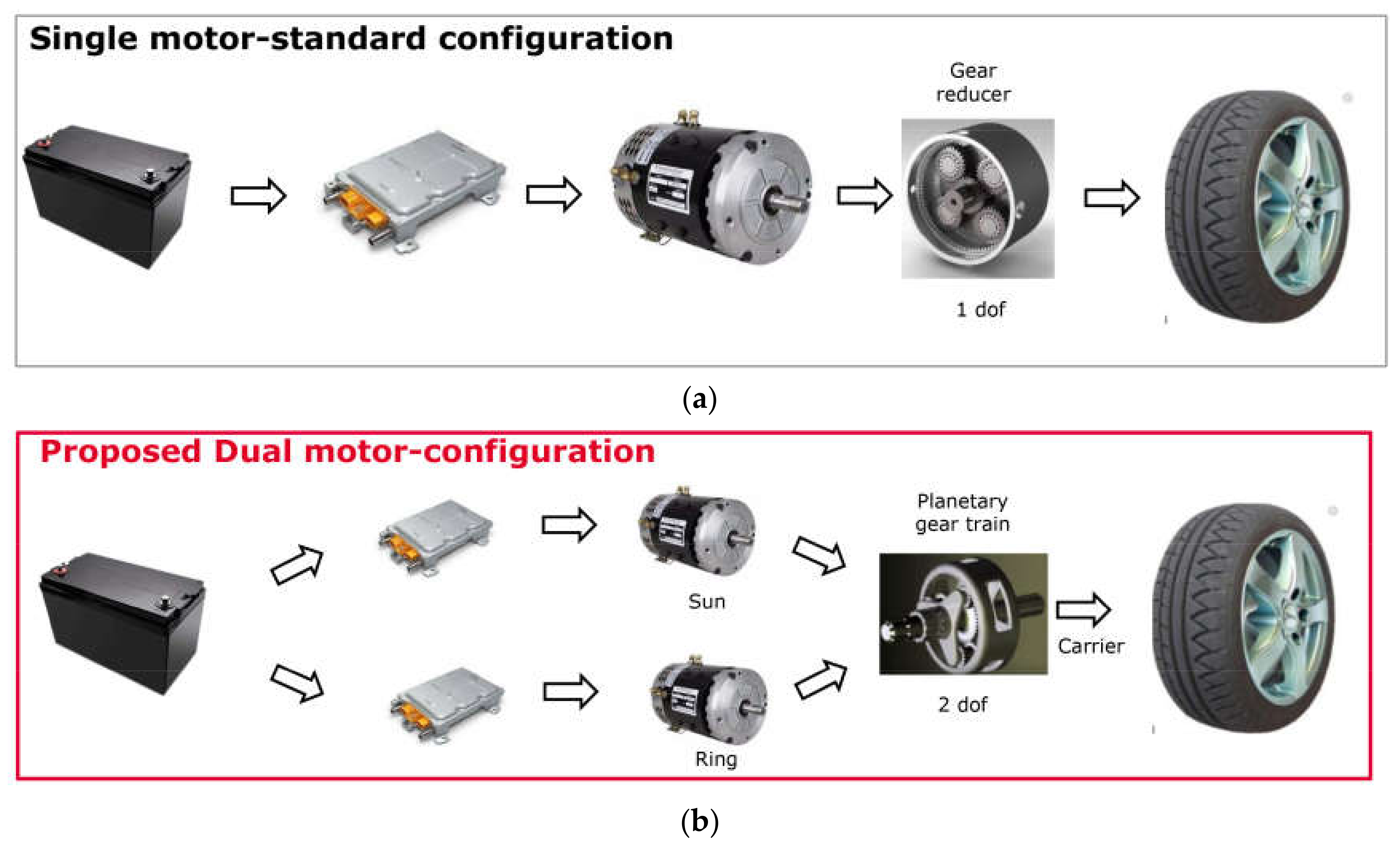
Figure 1 shows a comparison between the functional scheme of the standard single-motor, single-speed powertrain (
Figure 1a) and the proposed dual-motor multispeed alternative (
Figure 1b). In the standard configuration, the speed of the single motor is tightly connected with the speed of the car. Therefore, when the vehicle drives at low speed, the traction motor operates at low efficiency. In contrast, in the proposed dual-motor configuration, the speed range of the two smaller drive motors can be uncoupled from that of the vehicle, ensuring the best efficiency for both motors for any load condition.
The main contributions of this research are: (i) evaluation of the increase in the energy efficiency of the proposed powertrain over different standard drive cycles; (ii) definition of the optimal nominal requirements of the planetary gear and electric motors; (iii) a control strategy to set the operating condition of the two electric motors in order to maximize the efficiency of the powertrain. While the idea of a dual-motor multispeed powertrain was preliminarily introduced in [
21], this paper represents a substantial extension that introduces a discussion on: (a) system operations during regeneration stages; (b) the adoption of two different configurations of planetary gear that use a single-planet and a double-planet set; (c) the mechanical efficiency of the planetary gear that is explicitly modeled; (d) the performance evaluation of the powertrain for different standard driving cycles; (e) the optimal control strategy for the dual-motor planetary coupling based on a genetic algorithm.
As a final remark, it should be noted that today many hybrid vehicles use a planetary gear transmission. For example, in the Toyota Prius, the combustion engine is connected to the carrier while one generator is connected to the sun gear. Finally, the ring gear is coupled to the final drive, as is a second electric motor [
22]. During normal operations, the ring gear velocity is determined by the vehicle speed, while the first motor speed can be controlled with the aim to keep the combustion engine in its best efficiency window. Other recent applications can be found in robotics, where the use of multiple motors for a single revolute joint is evaluated in [
23], whereas a customized planetary gear train for human limb assistance and replication is discussed in [
24]. Here, we investigate the use of a planetary gear for the power transmission of full electric vehicles with the aim to uncouple the speed range of two electric motors from that of the car and keep both electric machines in their optimal efficiency window.
2. Powertrain Modeling
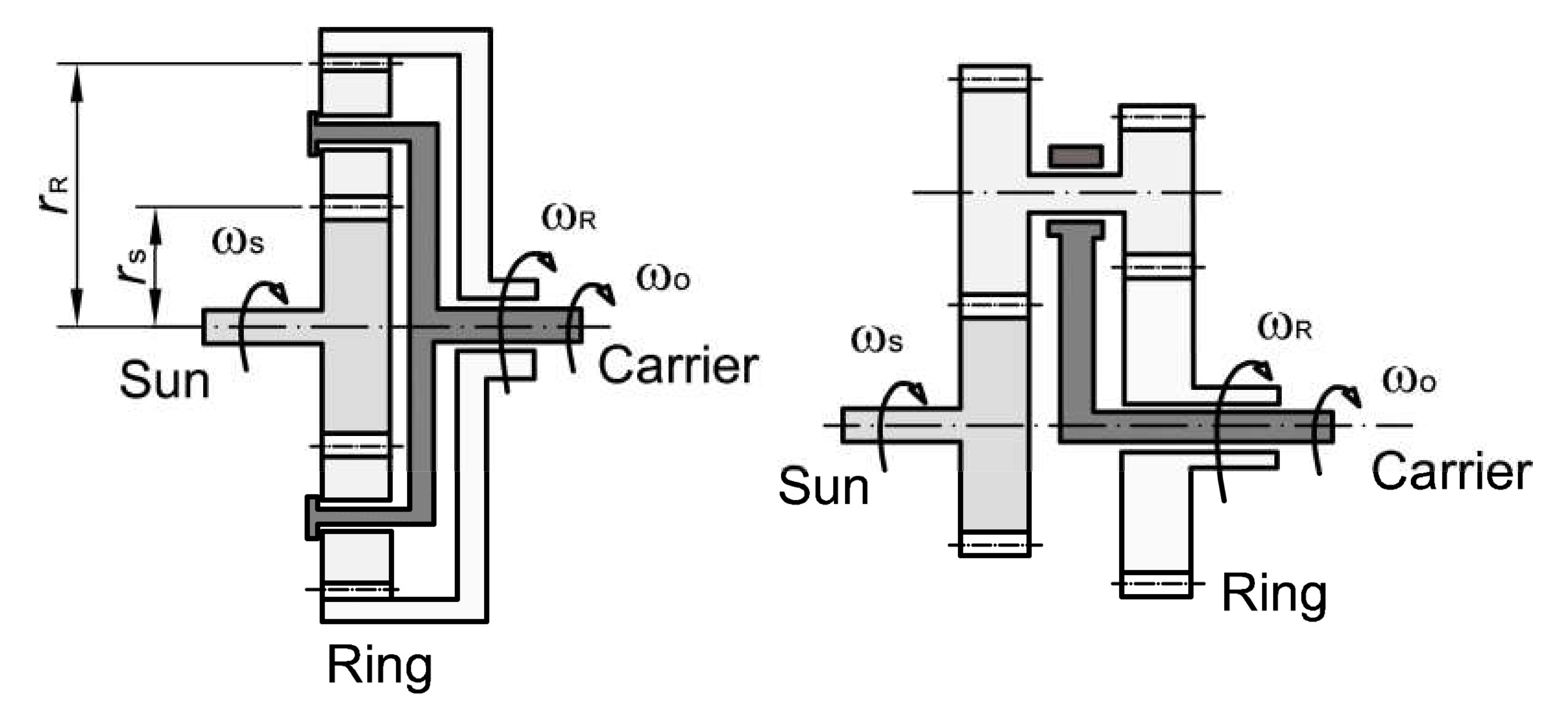
In the proposed dual-motor configuration, the planetary gear plays a critical role as it allows the speed range of the car to be uncoupled from that of the two drive motors. With reference to
Figure 2, a typical planetary gearbox comprises a sun gear that is attached to the first motor, a ring gear that is connected to the second motor, and a carrier that is attached to the external load. Two different configurations of epicyclic gear can be considered that use a single or a double planet set, as shown, respectively, on the left and right of
Figure 2.
First, the basic kinematic relationships of the planetary gear train are recalled, [
25], as follows
where
ωS,
ωR,
ωo are the velocities, respectively, of the sun, the ring, and the carrier of the planetary gear,
ρ = rR/
rS the ratio between the primitive radius of ring and sun, and
i = ωR/
ωS. Given
ρ that defines the planetary gear geometry, the speed of the carrier
ωo results as the weighted sum of the velocities of the sun and the ring,
ωS and
ωR; according to Equation (3) that is the only kinematic constraint of the system. Therefore, once the carrier velocity
ωo is set by the required vehicle velocity, there is one remaining degree of freedom,
i, that defines the relationship between the sun and the ring speed according to Equations (1) and (2), and that is the variable used in the parametric optimization process described later.
Looking at the energy balance of the system, the following relationship holds
where
TS and
TR refer, respectively, to the sun and ring torque,
To is the torque request, and
ηpd is the efficiency of the planetary gear. Equation (4) holds true for steady-state conditions. However, it can be considered a good approximation during transients as well if the motor inertia is small enough.
The efficiency of the planetary gear can be defined following [
26] as
where
refers to the efficiency of the equivalent ordinary gear train.
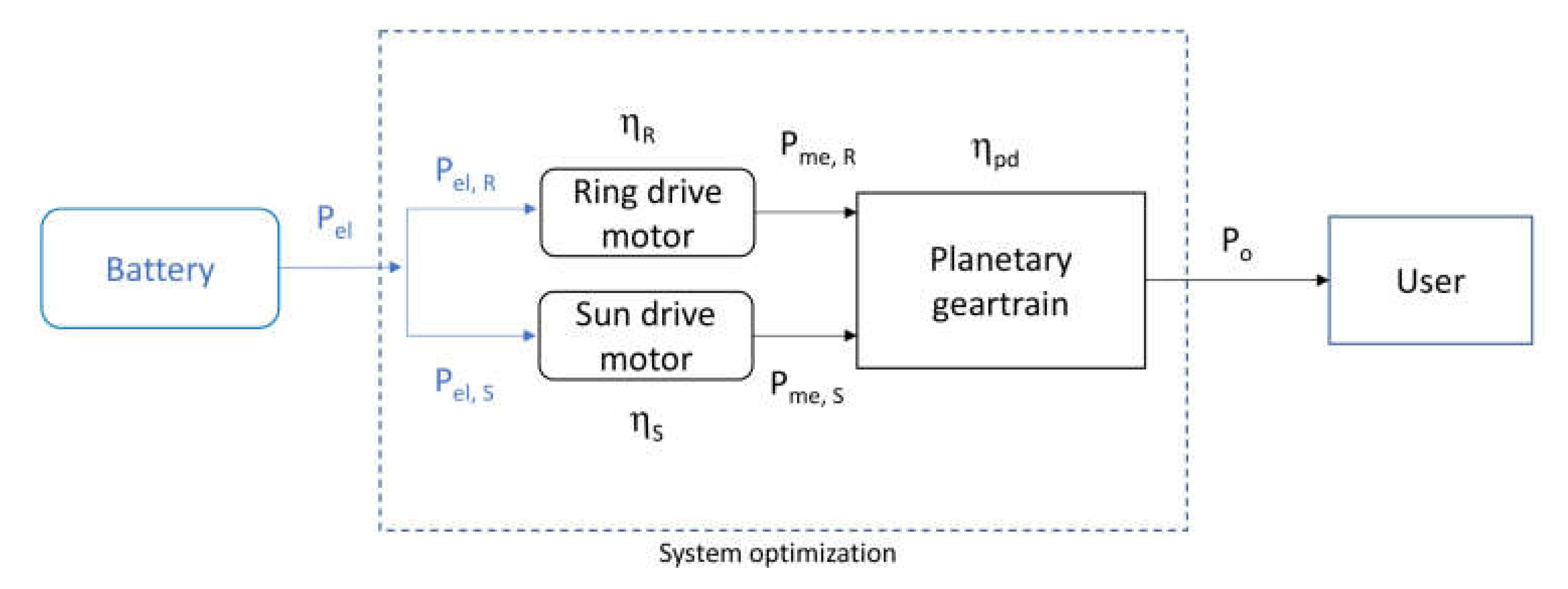
One important aspect of this study refers to the definition of the efficiency of the dual-motor powertrain,
. With reference to
Figure 3,
can be expressed during positive power supply as
where
PmeR/S is the mechanical power delivered by the ring/sun motor, and
PelR/S and
the corresponding electrical power and single motor efficiency, respectively. Note that in this analysis the loss in the power converters is not explicitly considered.
During the regenerative stage, the powertrain efficiency can be defined instead as
where
is the ring/sun regenerative motor efficiency.
3. Electric Motor and Load Modeling
The electric motor map needs to be defined. Without loss of generality, a normalized efficiency map can be obtained for a standard induction motor [
27], as shown in
Figure 4, under the assumption of relatively limited variation in the rated power. This map can be used for both the power delivery and regeneration stages without losing much accuracy.
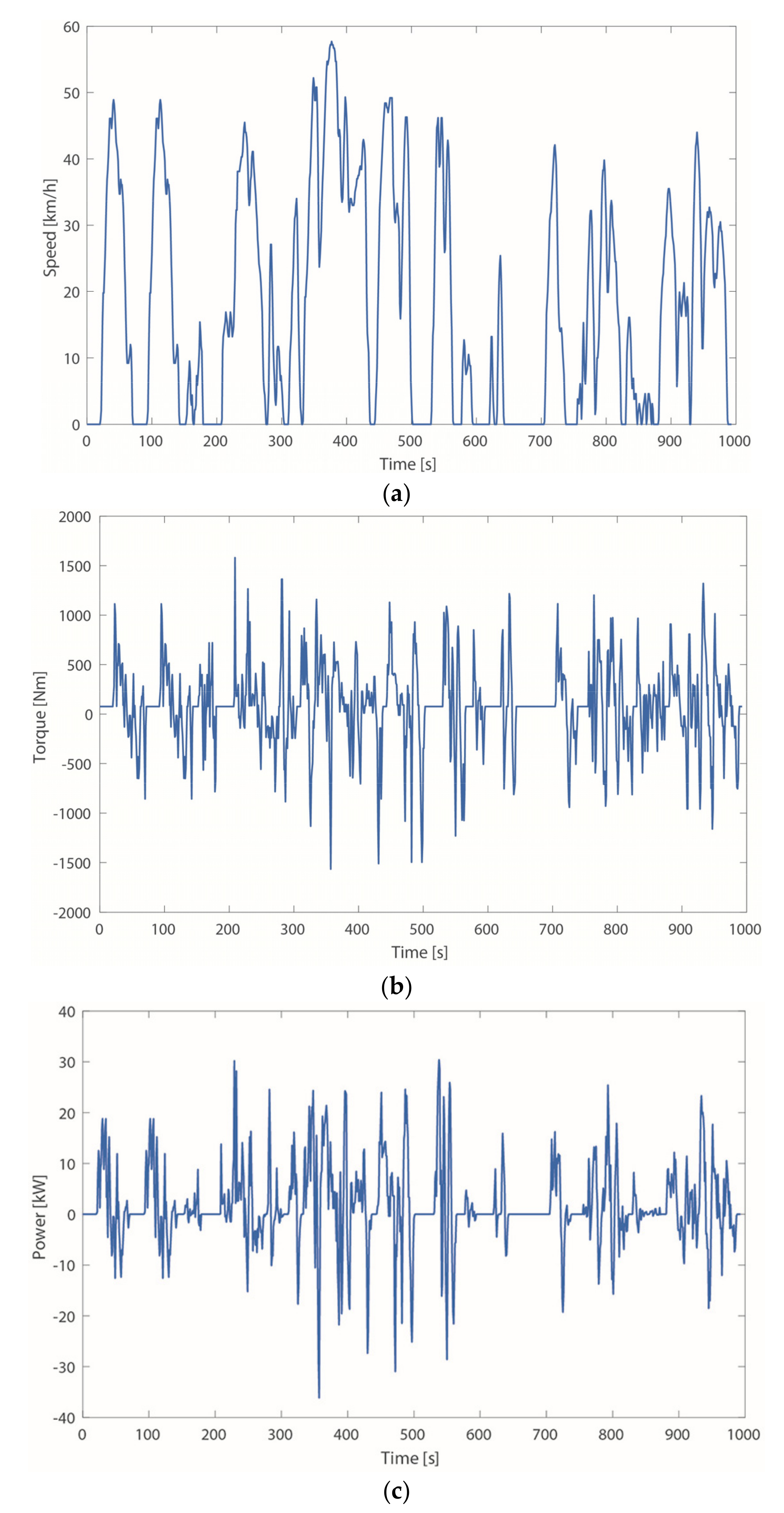
Load profiles for electric vehicles are described by various standard drive cycles (DC); for example, the Artemis urban cycle that is shown in
Figure 5 in terms of velocity, torque, and power requirement. The Artemis DC develops for about 4.8 km during a 993 s-time window with an average 17.6 km/h velocity.
The power and torque demand, respectively,
Po and
To, can be obtained under the assumption of planar driving as:
where
M is the vehicle apparent mass,
and
R the angular velocity and radius of the tires, and
fv the rolling resistance, whereas
define the aerodynamic resistance. The values of the vehicle parameters used in this research are collected in
Table 1. The maximum vehicle speed is assumed as 115 km/h.
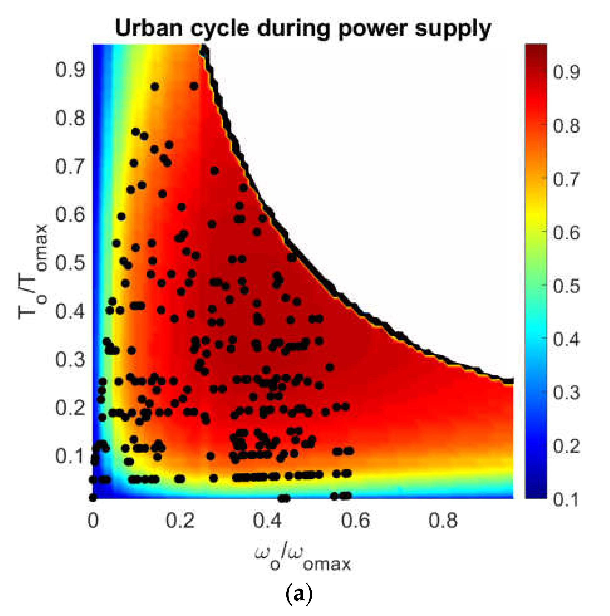
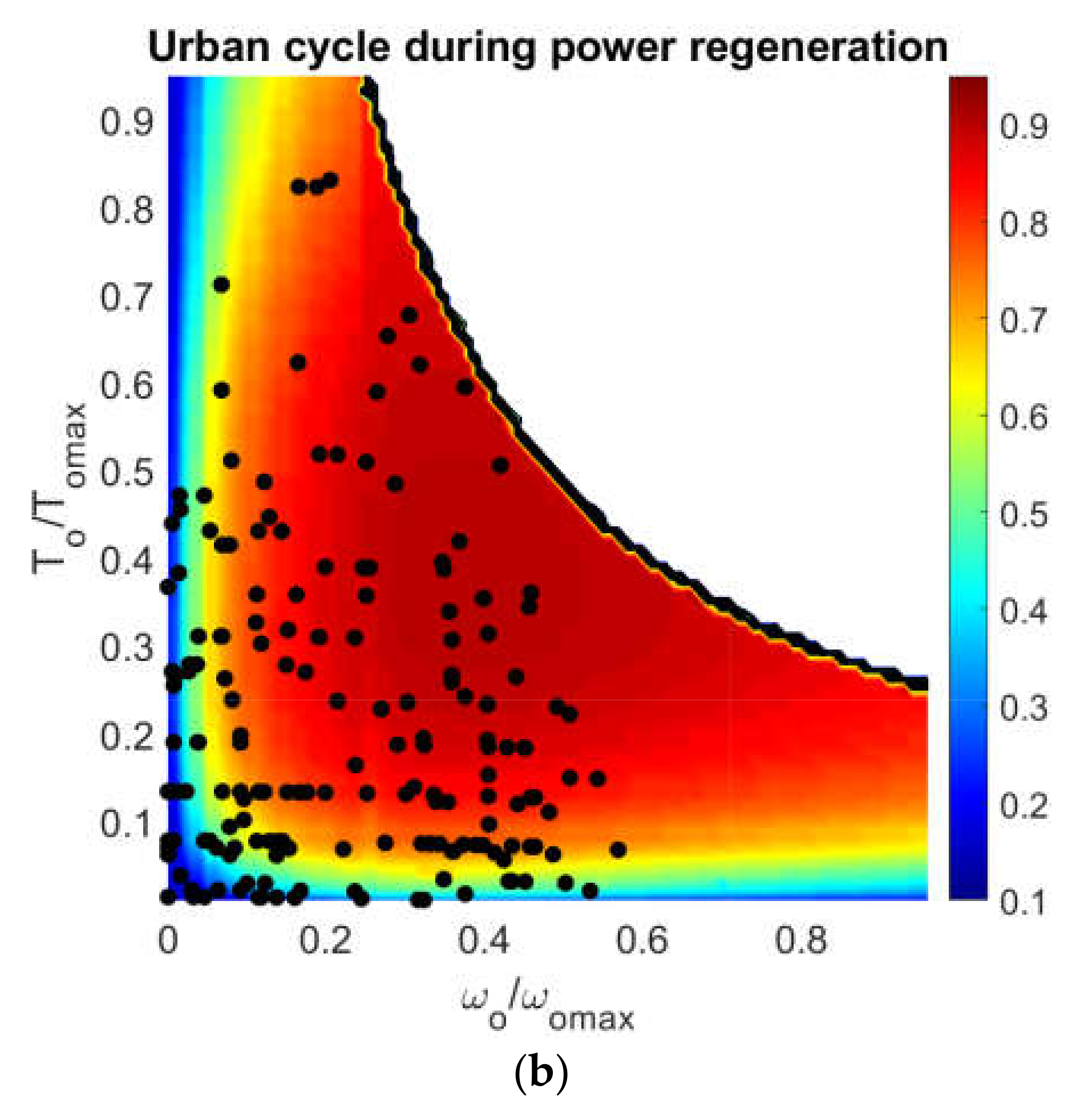
The load profile of the Artemis DC, expressed in terms of the operating pair (
), is overlaid over the normalized efficiency map of the single-motor architecture in
Figure 6, respectively, for the power supply (
Figure 6a) and regeneration (
Figure 6b) phase. It is interesting to note that when the vehicle is required to drive at low speed and high torque, the efficiency of the single-motor powertrain tends to degrade, as is apparent from the associated color map.
4. Controller and Design Optimization
In this research, two powertrains are contrasted: (a) one electric motor that is directly connected to the wheels providing the user-required power; and (b) two electric motors integrated with a planetary gear train that provide equal power to the single-motor powertrain.
The idea is that by uncoupling the load velocity profile of the vehicle with that of the two electric motors via the planetary gear, the powertrain efficiency can be improved. The control strategy and the technical requirements of the dual-motor powertrain can be defined through a two-step optimization process.
First, the strategy to set the best speed of the two motors for any given operating point is defined. Then, the geometrical constraint of the planetary gear and the power rates of the electrical motors are selected to provide optimal results over a standard drive cycle. In more detail, the two optimization stages are:
Optimization of the ratio i that maximizes the efficiency ηtot for each operating pair (ωo, To), given [ρ ωR,max ωS,max].
Optimization of the parameter set [ρ, ωR,max, ωS,max] to obtain the highest average efficiency over an urban cycle, ηcyc.
4.1. Dual-Motor System Control
Given the current load demand, the combination of motor speeds that is the ratio
i between them needs to be chosen to ensure the best efficiency for a fixed value of the planetary gear ratio,
ρ, and a maximum speed of the ring and sun motor. The functions to be maximized for the power delivery and regeneration stage are, respectively:
subject to the constraints expressed by Equations (2) and (4). In order to find the best solution, a genetic algorithm (GA) is adopted that is one type of global, derivative-free, and stochastic approach widely used to solve optimization problems in the design of electric vehicles [
24]. The GA algorithm keeps a random population of N individuals (here 25), each defining a speed ratio
i in the range of interest [0, 100]. For a given individual, the decoding procedure results in a powertrain efficiency that is evaluated according to Equation (5). The selection stage is performed using selection and crossover.
Standard tournament selection is applied with a given tournament size (typically 3–5) and a tournament probability of pt (around 0.6–0.8), whereas single-point crossover with a probability of pcross (around 0.8–0.9) is adopted. Once two new individuals are formed, mutation is enforced with probability of pmut (about 0.06–0.1) with either creep mutation (probability of 0.5 and creep rate of 10% of the full range) or full-range mutation (probability of 0.5). In addition, to avoid the best speed ratio found so far being lost in the pursuit of the next generation, this speed ratio is passed to the next generation according to the concept of elitism.
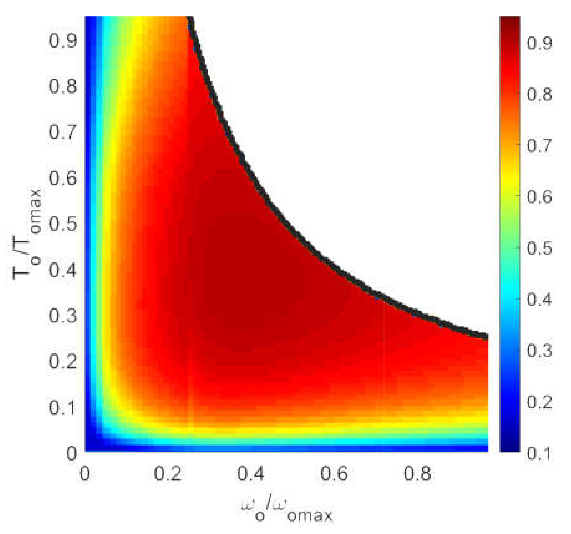
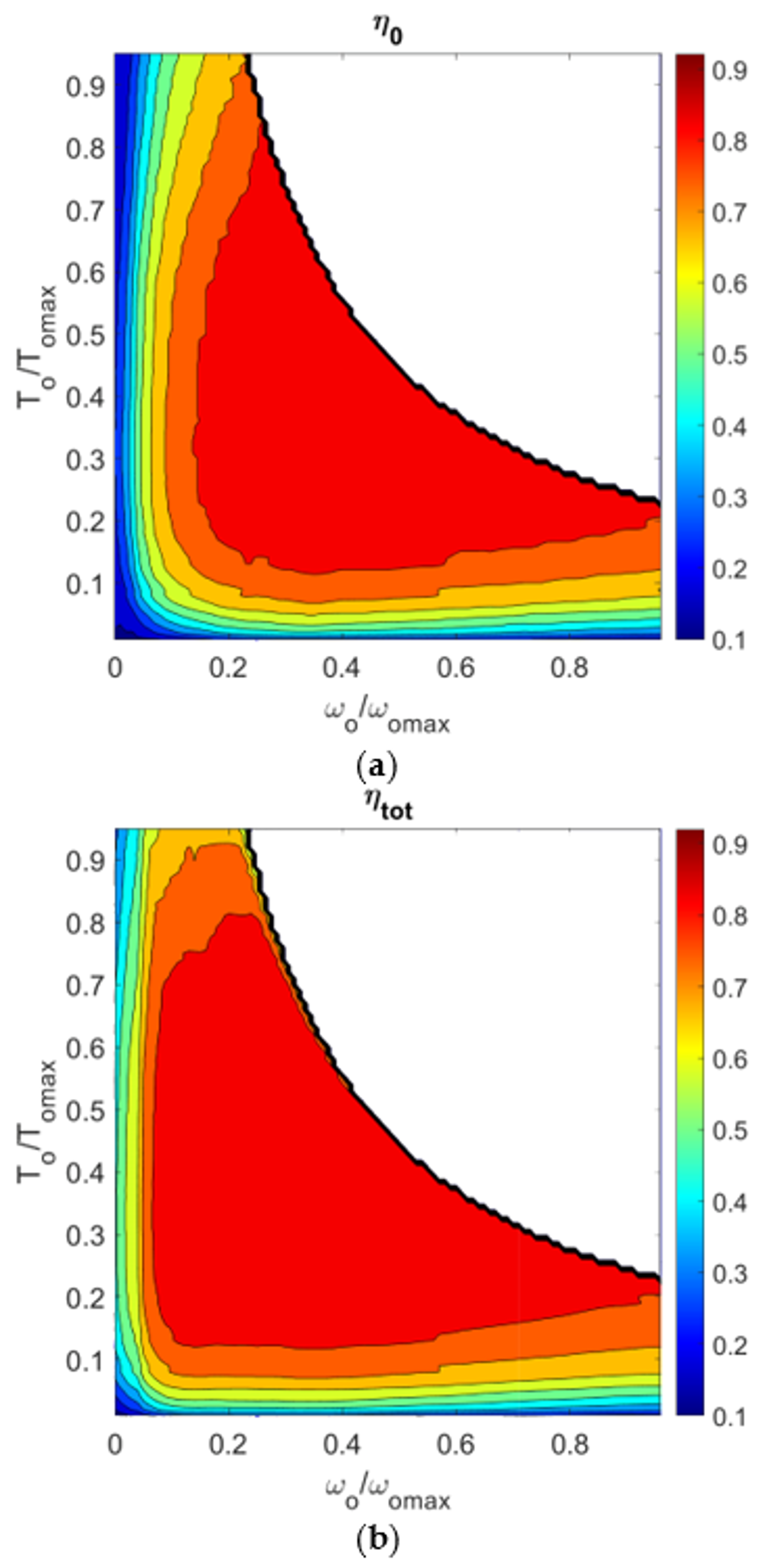
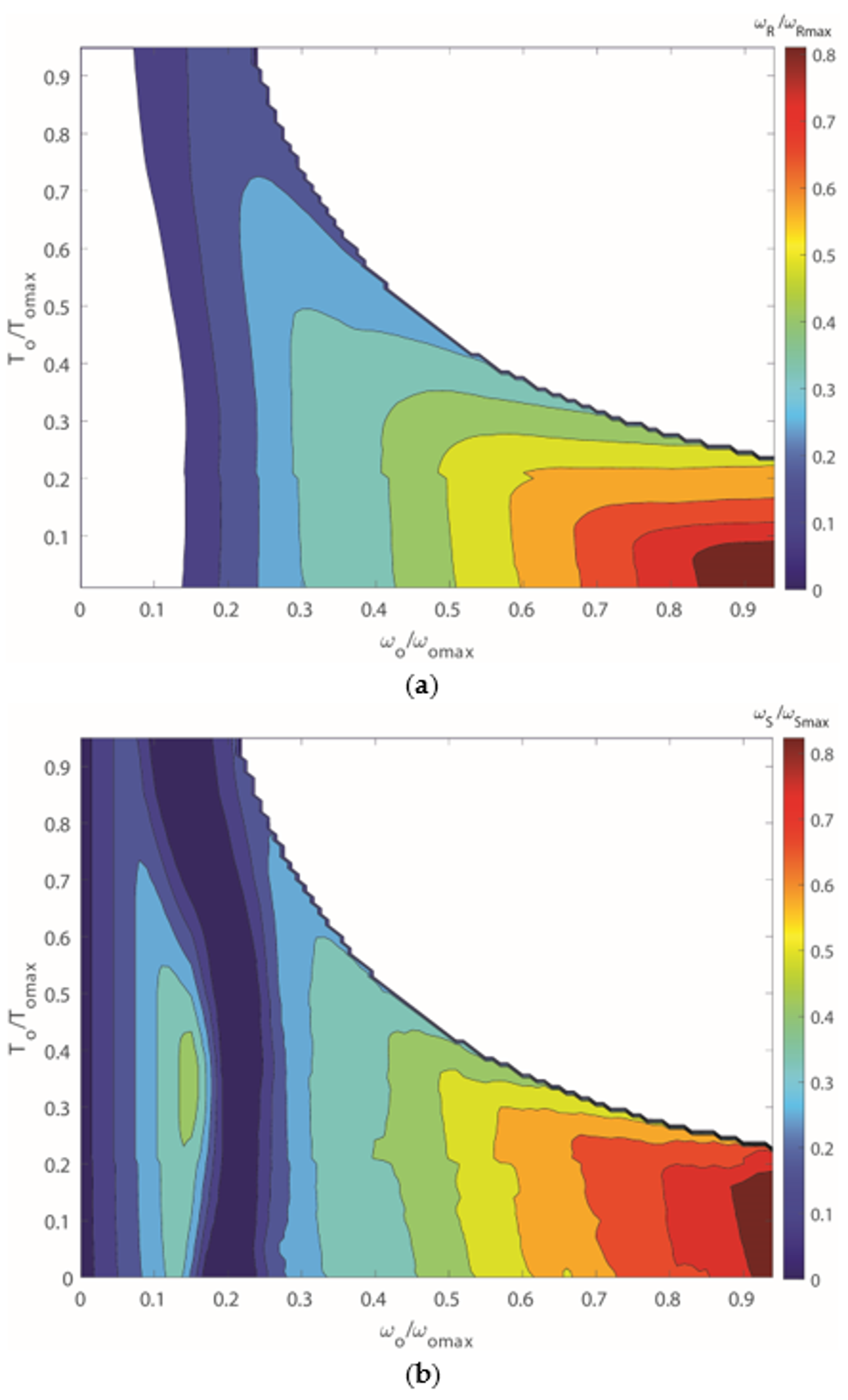
Results obtained from the first GA-based step of the optimization are shown in
Figure 7, where the efficiency of the optimized dual-motor powertrain,
ηtot (bottom plot), is compared against that of the single-motor,
η0 (upper plot). As expected, the largest discrepancy can be observed for low speed and high torque. The highest difference of about 0.24 (0.27 for regeneration) is found for a torque and a speed ranging, respectively, between 55% and 96% of the maximum torque and between 5% and 22% of the maximum speed.
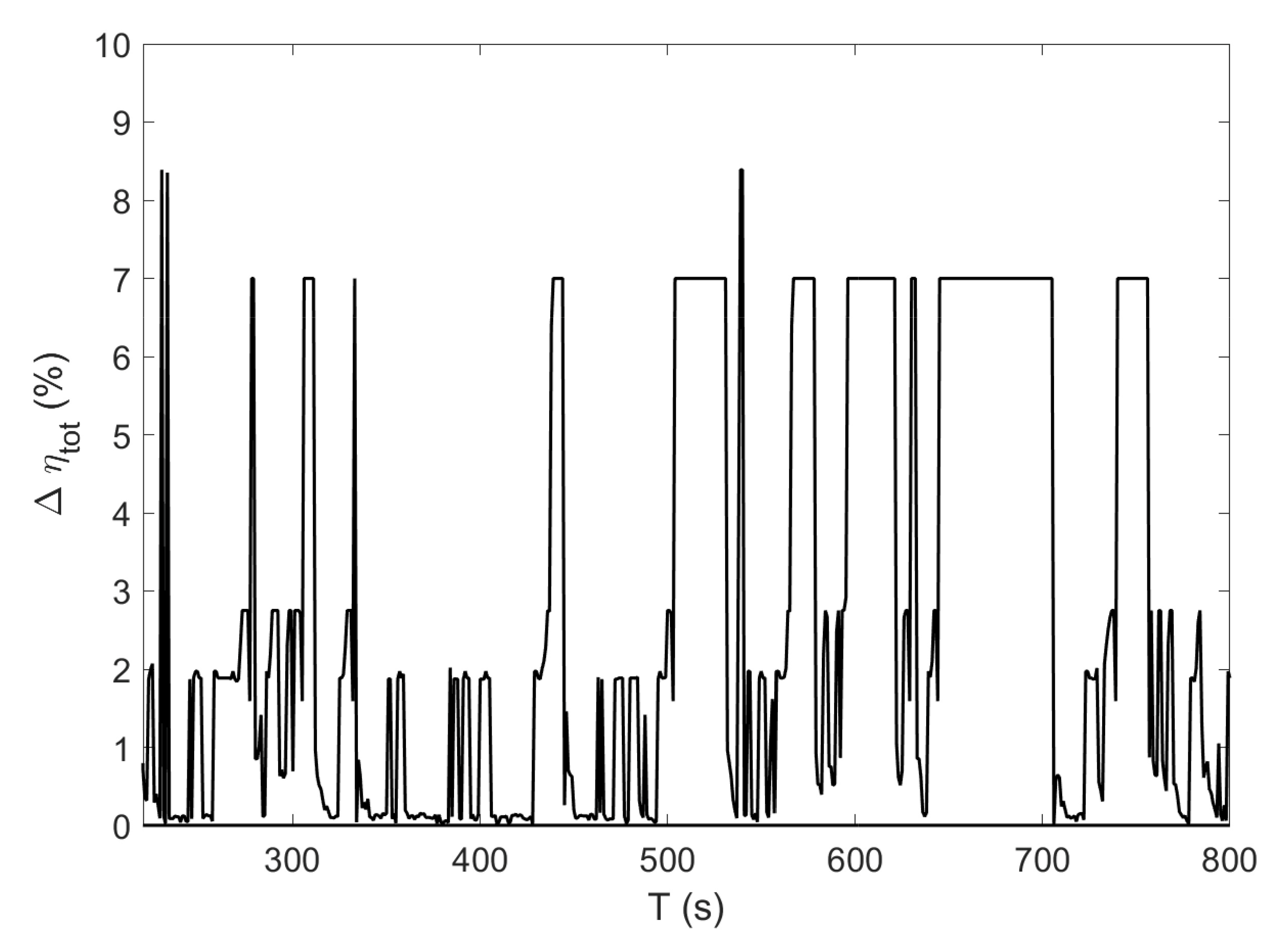
A direct comparison of the dual-motor powertrain with the single-motor configuration is shown in
Figure 8 in terms of relative energy efficiency improvement obtained over the Artemis DC. It is apparent that the better performance is from the dual-motor system that ensures better energy management with an increase in the efficiency that ranges from 0.4% up to 8.4%.
4.2. Powertrain Design
The previous optimization step can be iterated by varying the planetary gear ratio and the maximum velocity of the ring and sun motor. The best value for the parameter set [
ρ, ωR,max, ωS,max] can then be selected as the one that maximizes the average efficiency,
ηcyc, over the entire Artemis DC.
ηcyc is introduced as the ratio between the overall mechanical energy delivered during the urban cycle and the corresponding electric energy drawn by the motors:
In detail, the planetary gear ratio ρ has been changed from 2 to 4.6 for the single-planet epicyclical combiner (
Figure 2a), whereas the [−4.5, −2] range has been inspected for the double-planet set configuration (
Figure 2b). The maximum velocity of the ring motor (
ωmaxR) has been progressively incremented in the window [
ωo/2,
ωo·(
ρ + 1)/
ρ]. The upper limit corresponds to the maximum speed of the ring motor when the power of the sun motor is null. It is worth noting that, when the maximum velocity of the ring is set, in turn, the highest speed of the sun (
ωmaxS) is also determined since the power of the sun and the ring motors must be equal to the user-required power.
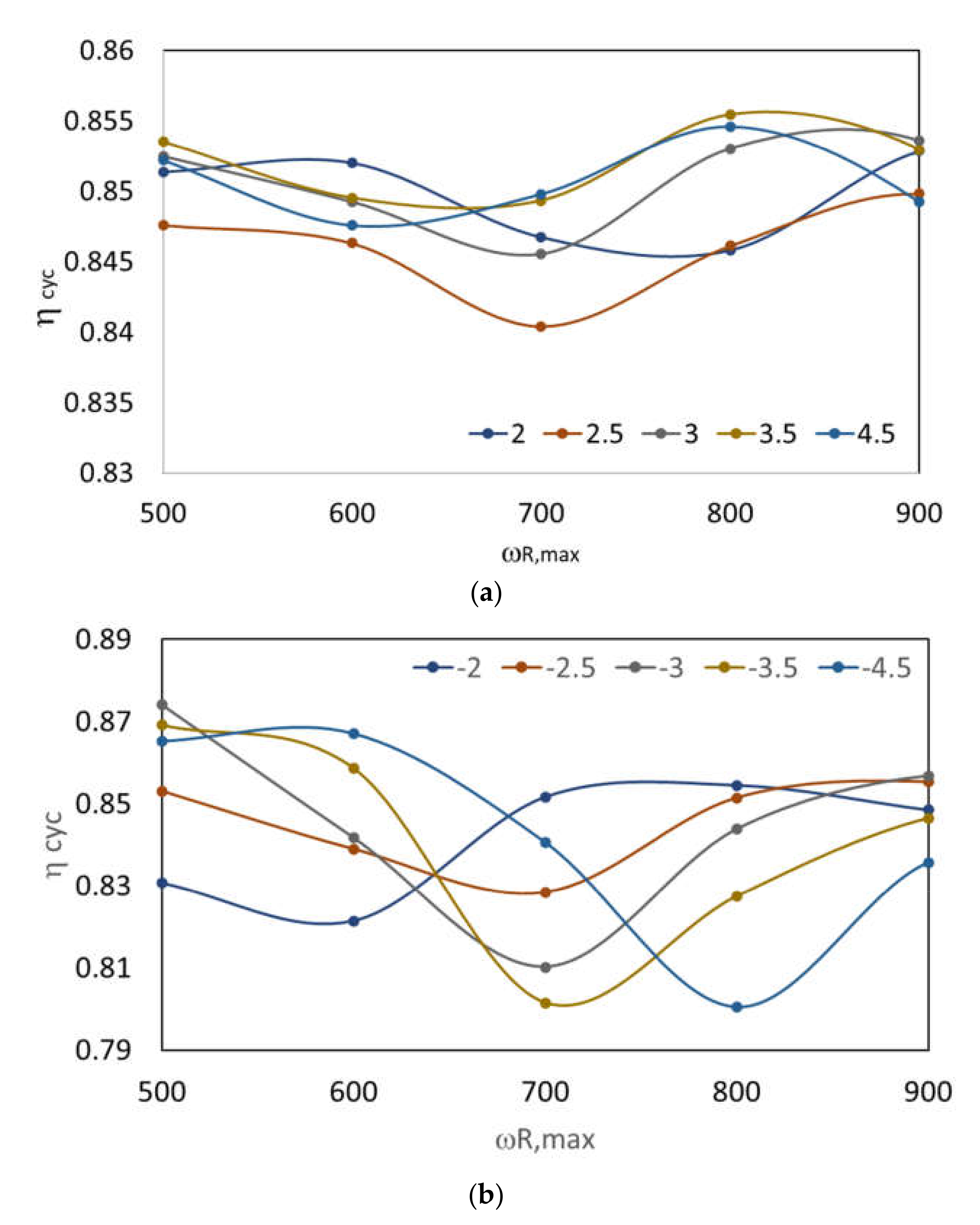
Results obtained from the powertrain design optimization are shown in
Figure 9. While the DC average efficiency is little affected by ρ and
ωmaxR when the single planet gear set is adopted (
Figure 9a), a larger impact is observed for the double-planet gear.
Table 2 collects the optimized values of
ωmaxR,
ωmaxS,
TmaxR,
TmaxS and
ρ, for both planetary gear types, showing that the dual-motor powertrain generally outperforms the single-motor counterpart,
ηo,avg, with an improvement in the overall efficiency estimated by Equation (11),
ηcyc,opt, of about 8.8% (8.9% during regeneration) for the single-planet and of about 8.7% (8.6% during regeneration) for the double-planet in the power delivery stage.
Note also that the optimal powertrain design is achieved when the two drive motors have a nominal power equal to 38% (22%) and 62% (78%) of the maximum power required by the vehicle, respectively, for the drive and sun motor, when the single- (double) planet combiner is adopted.
4.3. Optimization Results
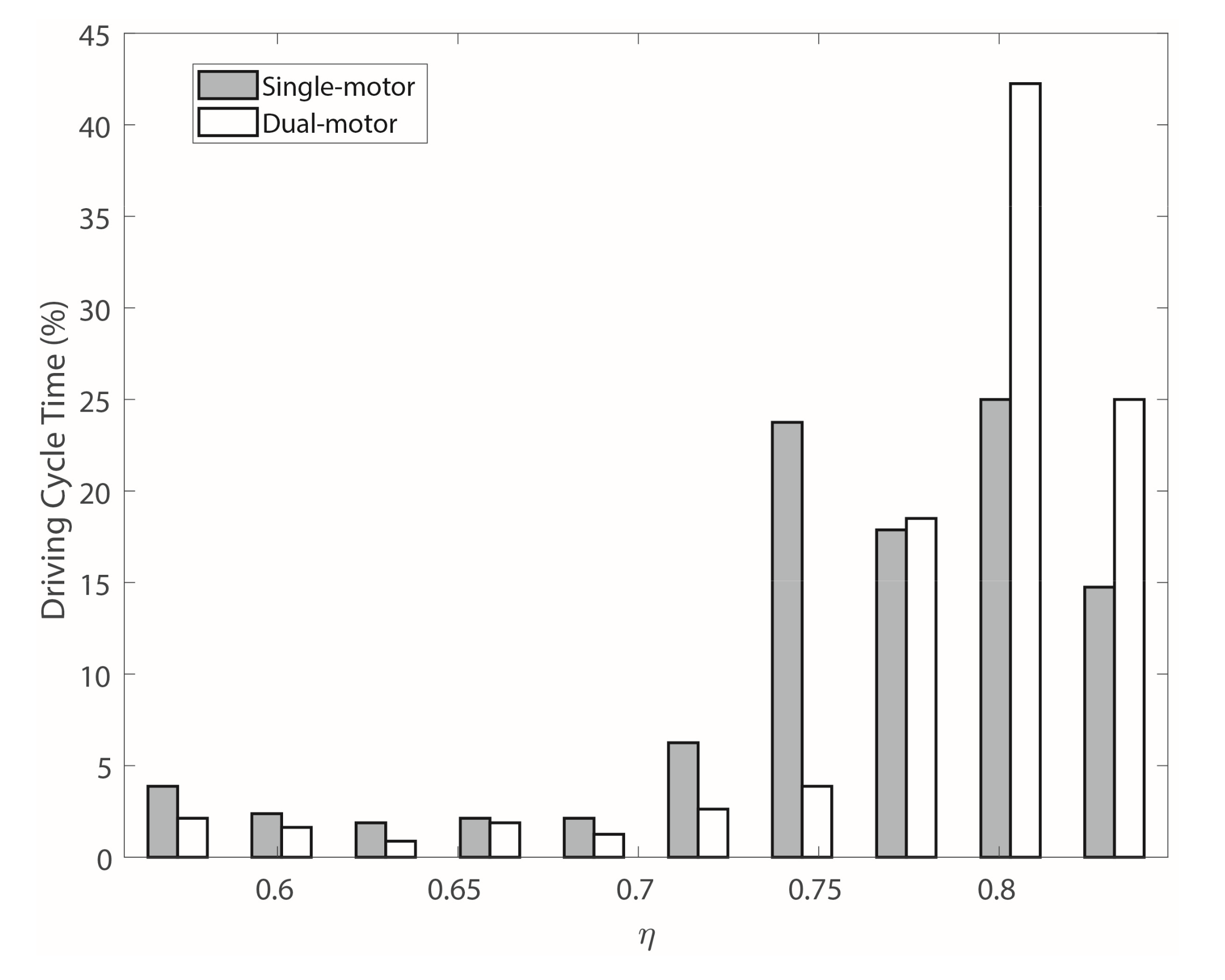
Since the time in which the motor remains in each efficiency region is a key parameter to ensure the best efficiency of the motor, the percentage driving cycle time is shown in
Figure 10 for ten discrete values of the efficiency range. Following the proposed approach, the transmission system operates with an efficiency greater than 0.8 for more than 70% of the time, which is a clear improvement compared to the standard single-motor system that ensures the same efficiency range for 42% of the driving cycle.
Moreover,
Figure 11 shows the velocity profile of the ring and sun motor (normalized with respect to the corresponding maximum value) that minimizes the energy consumption over the Artemis DC with reference to the optimized single-planet powertrain.
As seen from this figure, the sun motor is the only one that operates at low vehicle speed (i.e., ωo < 0.15 ωo,max), whereas the ring motor is blocked. In this working condition, the planetary gear works as a fixed-ratio reducer. At high vehicle velocity (i.e., ωo > 0.7 ωo,max), power is supplied simultaneously by both motors, as expected due to the design constraint that imposes that the maximum power demand must be balanced by the sum of the power delivered by the two motors. A similar behavior can be observed as well for the regeneration stage.
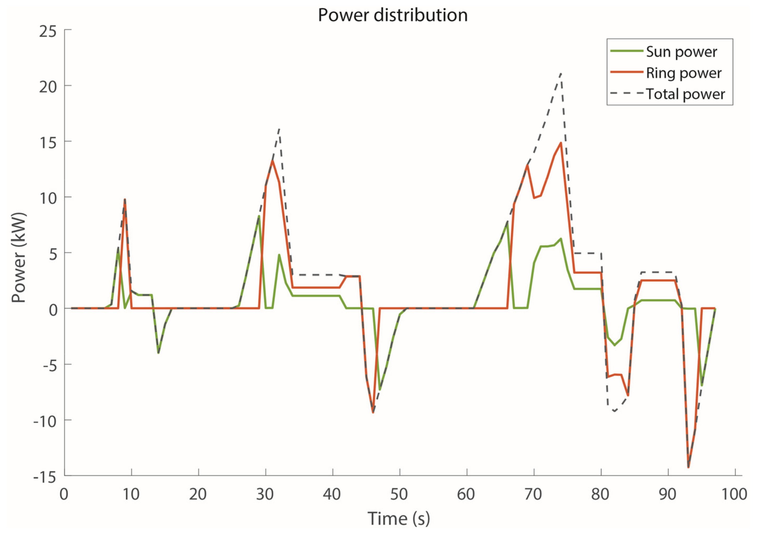
Finally, the power distribution between the sun and ring motor is shown in
Figure 12 for the first 100 s of the Artemis DC. During the positive power stages, the sun motor is the only one active when low power and high torque demand is required. Conversely, for high speed and low torque (constant high speed), the ring motor is the only one delivering power. Both motors operate simultaneously when about 85% of the maximum power is required.
4.4. Performance over Different Driving Cycles
For a general evaluation of the optimized dual-motor powertrain, its performance is now estimated for various standard driving cycles, namely the urban driving cycle ECE-15, the Artemis rural road cycle, and the Artemis motorway cycle [
28]. For each cycle, the relative percentage efficiency improvement obtained from the dual-motor powertrain with respect to the single-motor configuration is calculated considering both operating conditions of power delivery and regeneration. In addition, the two possible embodiments of the dual-motor transmission using single- and double-planet set are evaluated. Results are collected in
Table 3, showing that the proposed dual-motor architecture consistently outperforms the standard power transmission with an average increment of, respectively, 6.5% (11.3% for regeneration) and 7.4% (12.3% for regeneration) when the single-planet and the double-planet set are adopted. The largest efficiency gain is recorded for the ECE-15 urban DC using the double-planet set with a 10.9% improvement.
5. Conclusions
A novel architecture for full-electric vehicles was proposed that combines two motors through a planetary gear, allowing both motors to operate in their high efficiency range. This solution fits very well city cars that are characterized by a highly variable operating range. An optimization process allowed the controller and the system design to be set. The proposed dual-motor multispeed powertrain was compared with a standard single-motor, single-speed transmission, showing better efficiency in various driving cycles. As an example, for the Artemis urban cycle, an average improvement of about 9% was found for both the power supply and regeneration phase, ensuring the same maximum velocity, mechanical torque, and power. Similar results were obtained from other driving cycles. As expected, the largest improvements were observed at low speeds and large torques, attesting to the feasibility of the system for urban electric vehicles and, in general, for vehicles that operate at different speeds in diverse driving conditions.
Two types of planetary gears were investigated that feature a single-planet and double-planet set. They provided comparable results with a slight improvement obtained with the double-planet gear.
The dual-motor powertrain and the associated optimization framework can be potentially used to improve efficiency performance and thus autonomy of full-electric vehicles.
Future developments of this research will be devoted to validate experimentally the dual-motor powertrain in a laboratory test bench and on a vehicle test bed.


