
Design of Nonlinear Control of Gas Turbine Engine Based on Constant Eigenvectors †


Abstract
1. Introduction
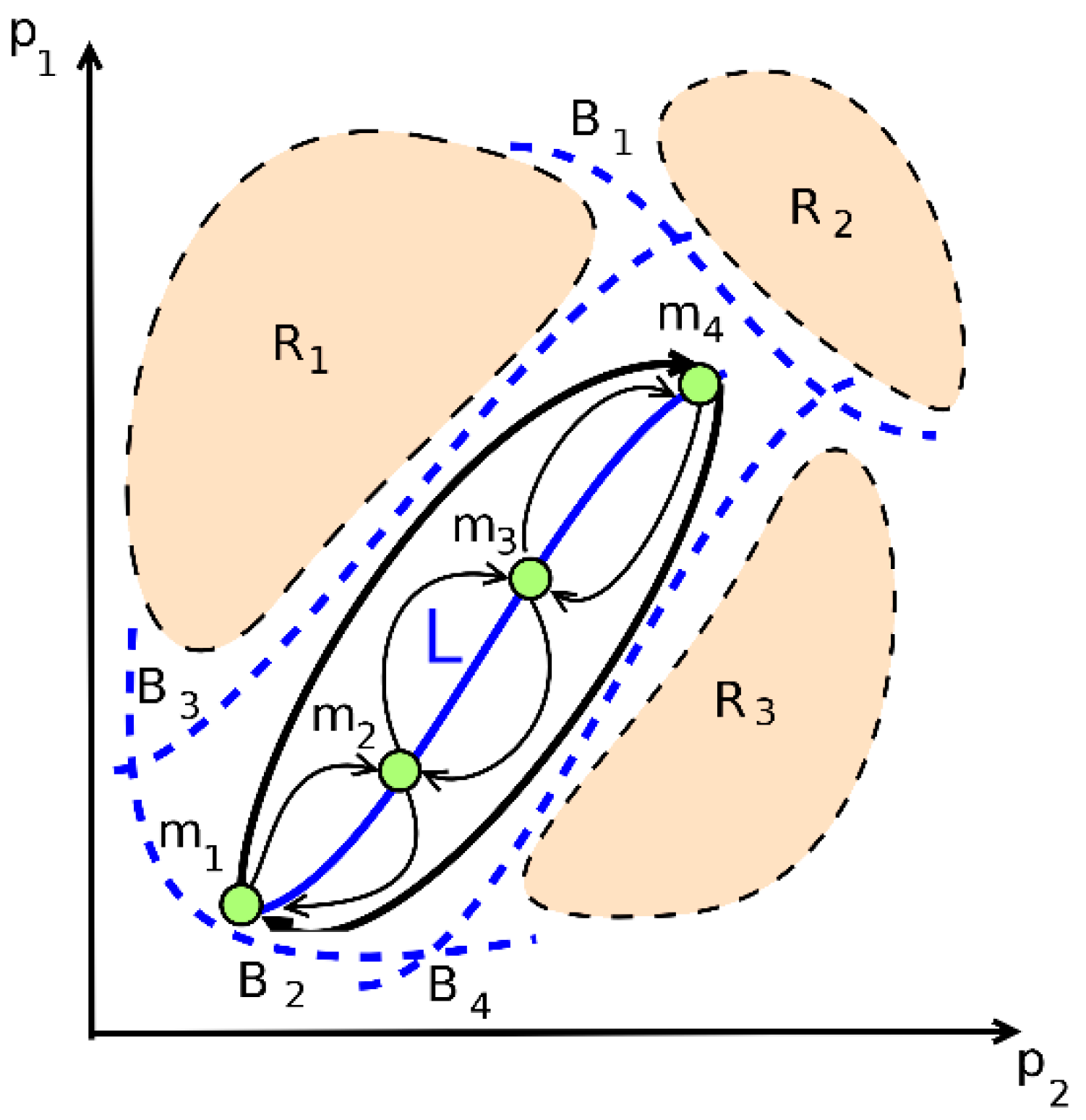
- P1 is compressor average pressure ratio;
- P2 is inlet corrected mass flow rate;
- R1 is compressor surge region;
- R2 is turbine gas temperature limit region;
- R3 is flameout region;
- mi are points on engine steady running line L;
- m1–m4 is the trajectory during acceleration;
- m4–m1 is the trajectory during deceleration;
- B1–B4 are the boundaries of stable operation of the compressor.
2. Nonlinear Control Design Method Based on Constant Eigenvectors
- Search for scalar control or vector control;
- Design control with complete or incomplete information;
- Control with complete or incomplete controllability of the eigenvalues of the closed system. Different algorithmic approaches are used depending on the type of control situation.
3. Neural Network Dynamic Model of a Gas Turbine Engine
- , ;
- are values of the vectors of variables x, u, y at static (steady-state) operating regimes of a gas turbine engine (i = 1, …, 4);
- is the vector of state variables (which are understood as the rotational speeds of the low and high pressure compressors of the gas turbine engine, respectively);
- is the vector of control actions (fuel consumption and jet nozzle cross-sectional area);
- is the vector of controlled variables (air pressure behind the compressor, gas pressure and temperature behind the turbine);
- is a parameter that determines the choice of the point of the i-th operating mode (or, respectively, the i-th piecewise linear model);
- are relative (dimensionless) values of variables N1 and N2.
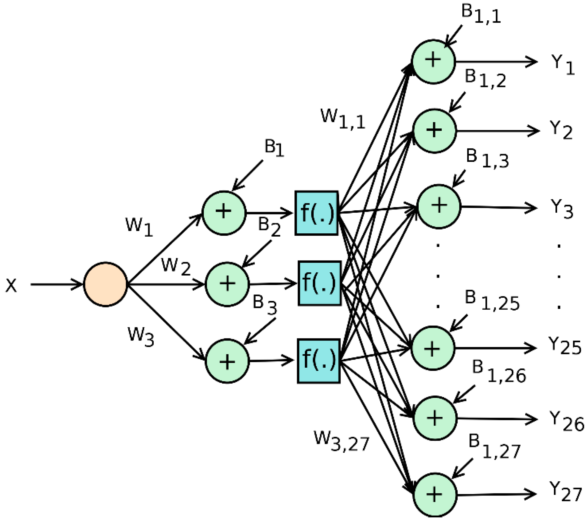
- fi (x) is neuron activation function (scalar function of vector argument);
- are configurable neural network weights;
- are biases in separate layers of the neural network, , where n is the number of neurons in the hidden layer.
4. Algorithm for Design of a Nonlinear Control System for Gas Turbine Engine
- i is the operating point (i-th operating regime) of the gas turbine engine.
- Identity (17) is not satisfied;
- Identity (17) is satisfied, but the real parts of the diagonal elements are positive;
- Identity (17) is satisfied, and the real parts of the diagonal elements are negative;
- Identity (17) is satisfied, and the matrix is the one with predominant diagonal elements, i.e., the condition is satisfied, where αj are off-diagonal elements of the i-th row.
5. Example of Nonlinear Control Design for a Gas Turbine Engine
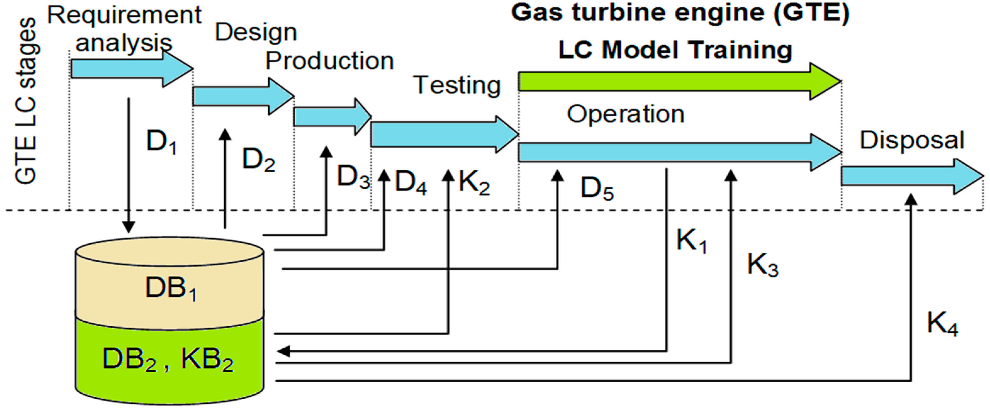
6. GTE Lifecycle and Nonlinear Control Design
- D1 is a formal gas turbine engine and controller description;
- D2, D3, D4, and D5 are data necessary for gas turbine engine and controller design, production, testing, and operation;
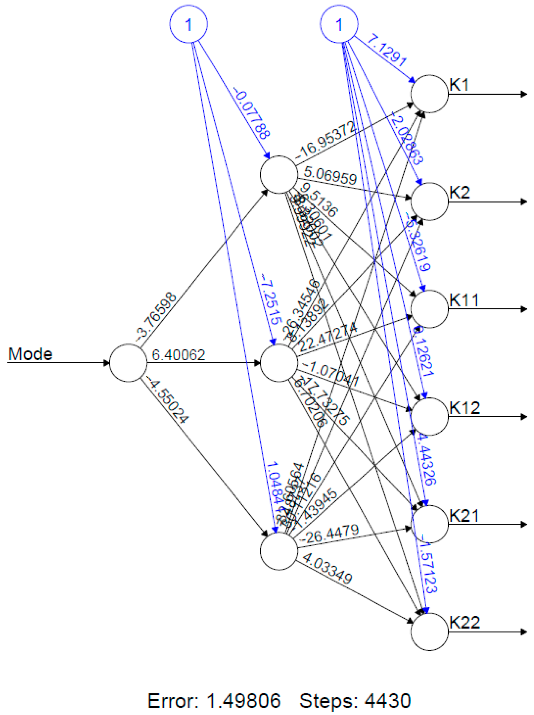
- K1 is the gas turbine engine and controller operation knowledge;
- K2 is control of test parameters;
- K3 is control of operation parameters;
- K4 is disposal control;
- DB1 and DB2 are integrated databases;
- KB2 is knowledge base.
7. Conclusions
Author Contributions
Funding
Institutional Review Board Statement
Informed Consent Statement
Conflicts of Interest
Nomenclature
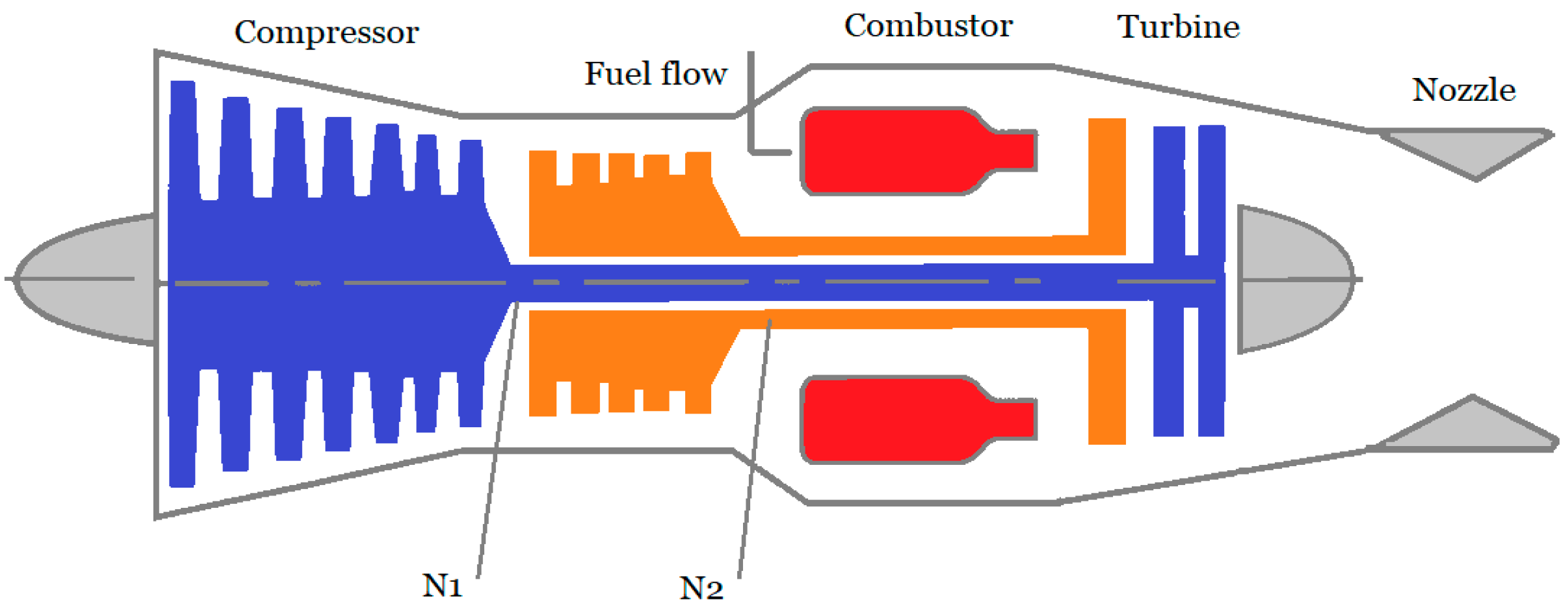
| N1 | Low pressure compressor rotational speed |
| N2 | High pressure compressor rotational speed |
| Wf | Fuel consumption |
| A8 | Jet nozzle cross-sectional area |
| P1 | Compressor average pressure ratio |
| P2 | Inlet corrected mass flow rate |
| R1 | Compressor surge region |
| R2 | Turbine gas temperature limit region |
| R3 | Flameout region |
| L | Steady running line |
| mi | Points on engine steady running line L |
| m1–m4 | Trajectory during acceleration |
| m4–m1 | Trajectory during deceleration |
| B1–B4 | Boundaries of stable operation of the compressor |
| Values of the vectors of variables x, u, y at static (steady-state) operating regimes of a gas turbine engine (i = 1, …, 4) | |
| Vector of state variables (which are understood as the rotational speeds of the low and high pressure compressors of the gas turbine engine, respectively) | |
| Vector of control actions (fuel consumption and jet nozzle cross-sectional area) | |
| Vector of controlled variables (air pressure behind the compressor, gas pressure and temperature behind the turbine) | |
| Parameter that determines the choice of the point of the i-th operating mode (or, respectively, the i-th piecewise linear model) | |
| Relative (dimensionless) values of variables N1 and N2 | |
| λ | Eigenvalue |
| Λ | Spectrum {λ} |
| M | Matrix of eigenvectors |
| t | Time (sec) |
| m | Eigenvector |
| G(.) | Eigenvalue function |
| f(.) | Neural network activation function |
| K | Nonlinear control |
| W | Weight matrix of neural network |
| Abbreviations | |
| SIMO | Single input–multiple output |
| GTE | Gas turbine engine |
References
- Soares, C. Gas Turbines: A Handbook of Air, Land and Sea Applications; Elsevier: Amsterdam, The Netherlands, 2015; pp. 173–254. [Google Scholar]
- MacIsaac, B.; Langton, R. Gas Turbine Propulsion Systems; John Wiley & Sons: New York, NY, USA, 2011; p. 328. [Google Scholar]
- Farokhi, S. Aircraft Propulsion; John Wiley & Sons: New York, NY, USA, 2014; p. 1048. [Google Scholar]
- Mattingly Jack, D. Elements of Propulsion: Gas Turbines and Rockets; AIAA Inc.: Reston, VA, USA, 2006; p. 928. [Google Scholar]
- Jaw, L.C.; Mattingly, J.D. Aircraft Engine Control Design, System Analysis, and Health Monitoring; AIAA Inc.: Reston, VA, USA, 2009. [Google Scholar]
- Gurevich, O.S. Aviation GTE Automatic Control Systems: Encyclopedic Reference; Gurevich, O.S., Ed.; Torus Press: Moscow, Russia, 2011. [Google Scholar]
- Jianguo, S.; Vasilyev, V.; Ilyasov, B. Advanced Multivariable Control Systems of Aeroengines; Sun, J., Vasilyev, V., Ilyasov, B., Eds.; BUAA Press: Beijing, China, 2005. [Google Scholar]
- Yamagami, J.; Okajima, K.; Koyama, O.; Yamamoto, S. Development of next generation gas turbine control systems. IHI Eng. Rev. 2008, 41, 74–79. [Google Scholar]
- Eres, M.H.; Scanlan, J.P. A Hierarchical Life Cycle Cost Model for a Set of Aero-Engine Components. In Proceedings of the 7th AIAA Aviation Technology, Integration and Operations Conference (ATIO), Belfast, Northern Ireland, 18–20 September 2007; AIAA Inc.: Reston, VA, USA, 2007. AIAA 2007-7705. [Google Scholar]
- Schobeiri, M.T. Gas Turbine Design, Components and System Design Integration; Springer: Cham, Switzerland, 2018; pp. 31–47. [Google Scholar]
- Vasilyev, V.; Valeyev, S. Sun Jianguo, Identification of Complex Technical Objects on the Basis of Neural Network Models and Entropy Approach. In Proceedings of the 9th World Multi-Conference on Systemics, Cybernetics and Informatics, Orlando, FL, USA, 10–13 July 2005; Volume IX, pp. 89–93. [Google Scholar]
- Ilyasov, B.; Vasilyev, V.; Valeev, S. Design of Multi-Level Intelligent Control Systems for Complex Technical Objects on the Basis of Theoretical-Information Approach. Acta Polytech. Hung. 2020, 17, 137–150. [Google Scholar] [CrossRef]
- Kulikov, G.G.; Thompson, H.A. Dynamic Modelling of Gas Turbines: Identification, Simulation, Condition Monitoring and Optimal Control, Advances in Industrial Control; Springer: London, UK, 2014. [Google Scholar]
- Kulikov, G.G.; Arkov, V.Y.; Abdulnagimov, A.I. Markov modelling for energy efficient control of gas turbine power plant. IFAC Proc. Vol. 2010, 43 Pt 1, 63–67. [Google Scholar] [CrossRef]
- Leith, D.J.; Leithead, W.E. Gain-scheduled and nonlinear systems: Dynamics analysis by velocity based linearization families. Int. J. Control 1998, 70, 289–317. [Google Scholar] [CrossRef]
- Pakmehr, M.; Fitzgerald, N.; Feron, E.M.; Shamma, J.S.; Behbahani, A. Gain Scheduling Control of Gas Turbine Engines: Stability by Computing a Single Quadratic Lyapunov Function. In Proceedings of the ASME Turbo Expo 2013: Turbine Technical Conference and Exposition, San Antonio, TX, USA, 3–7 June 2013. GT2013-96012, V004T06A027. [Google Scholar]
- Shamma, J.S.; Athans, M. Analysis of Gain Scheduled Control for Nonlinear Plants. IEEE Trans. Autom. Control 1990, 35, 898–907. [Google Scholar] [CrossRef]
- Sisworahardjo, N.; El-Sharkh, M.; Alam, M. Neural network controller for microturbine power plants. Electr. Power Syst. Res. 2008, 78, 1378–1384. [Google Scholar] [CrossRef]
- Nise, N.S. Control Systems Engineering; John Wiley & Sons: New York, NY, USA, 2019. [Google Scholar]
- Friedland, B. Control System Design: An Introduction to State-Space Methods; Dover: New York, NY, USA, 2005. [Google Scholar]
- Katsuhiko, O. Modern Control Engineering; Prentice Hall: Upper Saddle River, NJ, USA, 2010. [Google Scholar]
- Kolesnikov, A.A.; Kolesnikova, S.I. Synthesis Algorithm for a Continuous Robust Regulator on a Manifold for a Manipulator under Non-Random Noise Conditions. In Proceedings of the 2020 International Russian Automation Conference (RusAutoCon 2020), Sochi, Russia, 6–12 September 2020; pp. 291–295. [Google Scholar]
- Akhmetgaleev, I.I. Design of Nonlinear Control Systems with Matrix Approach; St. Petersburg State University of Aerospace Instrumentation Publ.: St. Petersburg, Russia, 1983. [Google Scholar]
- Akhmetgaleev, I.I. Design of Nonlinear Control Systems; St. Petersburg State University of Aerospace Instrumentation Publ.: St. Petersburg, Russia, 1984. [Google Scholar]
- Cybenko, G. Approximation by superpositions of a sigmoidal function. Math. Control Signals Syst. 1989, 2, 303–314. [Google Scholar] [CrossRef]
- Hornik, K.M.; Stinchombe, M.; White, H. Multilayer feedforward networks are universal approximators. Neural Netw. 1989, 2, 359–366. [Google Scholar] [CrossRef]
- Funahashi, K. On the approximate realization of continuous mappings by neural networks. Neural Netw. 1989, 2, 183–192. [Google Scholar] [CrossRef]
- Pinkus, A. Approximation theory of the MLP model in neural networks. Acta Numer. 1999, 8, 143–195. [Google Scholar] [CrossRef]
- Gorban, A.N. Approximation of continuous functions of several variables by an arbitrary nonlinear continuous function of one variable, linear functions, and their superpositions. Appl. Math. Lett. 1998, 11, 45–49. [Google Scholar] [CrossRef]
- Vasilyev, V.; Ilyasov, B.; Kusimov, S. Neurocomputers in Aviation; Radiotechnica Pub.: Moscow, Russia, 2004. [Google Scholar]
- Valeev, S.; Kondratyeva, N. Design of Nonlinear Multi-Mode Controller for Gas Turbine Engine in State Space Based on Algorithmic Approach. In Proceedings of the 2020 International Russian Automation Conference (RusAutoCon 2020), Sochi, Russia, 6–12 September 2020; pp. 1053–1057. [Google Scholar]
- Sanchez, E.N.; Rios, J.D.; Alanis, A.Y.; Arana-Daniel, N. Neural Networks Modeling and Control; Academic Press: Cambridge, MA, USA, 2020. [Google Scholar]
- Agarwal, M. A systematic classification of neural-network-based control. Control Syst. 1997, 17, 75–93. [Google Scholar]
- Narendra, K.S.; Mukhopadhyay, S. Adaptive control using neural networks and approximate models. IEEE Trans. Neural Netw. 1997, 8, 475–485. [Google Scholar] [CrossRef] [PubMed]
- Mu, J.; Rees, D.D. Approximate model predictive control for gas turbine engines. In Proceedings of the 2004 American Control Conference, Boston, MA, USA, 30 June–2 July 2004; Volume 1/6, pp. 5704–5709. [Google Scholar]
- Sahin, S.; Savran, A. A neural network approach to model predictive control. In Proceedings of the 14th Turkish Symposium on Artificial Intelligence and Neural Networks, Izmir, Turkey, 16–17 June 2005; pp. 386–392. [Google Scholar]
- Galushkin, A.I. Neural, Networks Theory; Springer: Cham, Switzerland, 2007. [Google Scholar]
- Wonham, W.M. Linear Multivariable Control: A Geometric Approach; Springer: Cham, Switzerland, 1985. [Google Scholar]
- Park, H.; Seborg, D.E. Eigenvalue Assignment Using Proportional-Integral Feedback Control. Int. J. Control 1974, 20, 517–523. [Google Scholar] [CrossRef]
- The R Project for Statistical Computing. Available online: https://www.r-project.org/ (accessed on 20 December 2020).
- GNU Octave. Available online: http://www.gnu.org/software/octave/ (accessed on 21 December 2020).
- Guichvarov, A.; Kondratieva, N. Technical and economic assessment of aircraft engines fatigue testing on base of simulation modeling. In Proceedings of the 37th AIAA/ASME/SAE/ASEE Joint Propulsion Conference and Exhibit, Salt Lake City, UT, USA, 8–11 July 2001; AIAA Inc.: Reston, VA, USA, 2007. [Google Scholar]
- Kondratyeva, N.; Valeev, S. Fatigue Test Optimization for Complex Technical System on The Basis of Lifecycle Modeling and Big Data Concept. In Proceedings of the 2016 IEEE 10th Int. Conf. on Application of Information and Communication Technologies, Baku, Azerbaijan, 12–14 October 2016; IEEE Publishing: New York, NY, USA, 2016; pp. 1–4. [Google Scholar]
- Zagitova, A.; Kondratyeva, N.; Valeev, S. Information Support of Gas-Turbine Engine Life Cycle Based on Agent-Oriented Technology. In Proceedings of the 5th Int. Conf. on Industrial Engineering (ICIE 2019), Sochi, Russia, 25–29 March 2019; Radionov, A.A., Kravchenko, O.A., Guzeev, V.I., Rozhdestvenskiy, Y.V., Eds.; Springer: Cham, Switzerland, 2020; Volume I, pp. 469–476. [Google Scholar]
- GT Auto Tuner: First System Worldwide to Leverage Physics and Reinforcement Learning to Optimize Gas Turbine Operation. Available online: https://www.siemens-energy.com/global/en/offerings/services/digital-services/gt-autotuner.html (accessed on 17 December 2020).


| No. | Vector of the Model Coefficients | ||||
|---|---|---|---|---|---|
| 0.68 (m.1) | 0.78 (m.2) | 0.89 (m.3) | 0.95 (m.4) | ||
| 1 | a11 | −2.14 | −2.53 | −6.24 | −5.89 |
| 2 | a12 | 1.6 | 1.49 | 1.62 | 1.22 |
| 3 | a21 | −0.11 | −0.37 | −0.53 | −0.55 |
| 4 | a22 | −1.14 | −1.17 | −1.16 | −1.16 |
| 5 | b11 | 3.21 | 2.45 | 2.81 | 2.54 |
| … | … | … | … | … | … |
| 25 | p2st | 0.7 | 0.8 | 0.9 | 1 |
| 26 | p4st | 0.14 | 0.19 | 0.24 | 0.31 |
| 27 | T4st | 0.09 | 0.13 | 0.19 | 0.24 |
Publisher’s Note: MDPI stays neutral with regard to jurisdictional claims in published maps and institutional affiliations. |
© 2021 by the authors. Licensee MDPI, Basel, Switzerland. This article is an open access article distributed under the terms and conditions of the Creative Commons Attribution (CC BY) license (http://creativecommons.org/licenses/by/4.0/).
Share and Cite
Valeev, S.; Kondratyeva, N. Design of Nonlinear Control of Gas Turbine Engine Based on Constant Eigenvectors. Machines 2021, 9, 49. https://doi.org/10.3390/machines9030049
Valeev S, Kondratyeva N. Design of Nonlinear Control of Gas Turbine Engine Based on Constant Eigenvectors. Machines. 2021; 9(3):49. https://doi.org/10.3390/machines9030049
Chicago/Turabian StyleValeev, Sagit, and Natalya Kondratyeva. 2021. "Design of Nonlinear Control of Gas Turbine Engine Based on Constant Eigenvectors" Machines 9, no. 3: 49. https://doi.org/10.3390/machines9030049
APA StyleValeev, S., & Kondratyeva, N. (2021). Design of Nonlinear Control of Gas Turbine Engine Based on Constant Eigenvectors. Machines, 9(3), 49. https://doi.org/10.3390/machines9030049