Article

Dynamic Response of Planetary Bearings in a Double Planetary Gear Train with Forward and Reverse Carrier Rotations

1
School of Mechanical Engineering, Beijing Institute of Technology, Beijing 100081, China
2
China North Vehicle Research Institute, Beijing 100072, China
3
School of Vehicle and Energy, Yanshan University, Qinhuangdao 066000, China
*
Author to whom correspondence should be addressed.
Machines 2026, 14(5), 539; https://doi.org/10.3390/machines14050539
Submission received: 7 April 2026 / Revised: 6 May 2026 / Accepted: 7 May 2026 / Published: 12 May 2026
(This article belongs to the Section Machine Design and Theory)

Abstract

Planetary bearings are critical components in double planetary gear trains. The influence of carrier rotation direction on bearing dynamic behavior remains insufficiently understood, which hinders accurate reliability assessment and optimal design. To investigate this issue, a dynamic model of the double planetary gear train is developed. The model captures the coupled interactions and motion characteristics of both gears and bearings. Furthermore, an experimental platform is constructed to validate the accuracy of the proposed model. A comparative analysis is conducted to examine the dynamic loads and vibration responses of the planetary bearings under forward and reverse carrier rotations. The results show that reverse rotation significantly intensifies collision forces, particularly under low-speed and high-torque conditions, where the increases for inner and outer bearings reach 38.34% and 31.25%, respectively. In terms of contact forces, the inner bearing exhibits higher loads under reverse rotation, whereas the outer bearing carries greater loads under forward rotation. Vibration response analysis reveals that the carrier rotation direction has a limited effect on the vibration of the inner bearing, but significantly amplifies that of the outer bearing. Under reverse rotation, the acceleration amplitudes of the outer cage in the x- and y-directions increase by 96.20% and 95.74%, respectively, markedly exceeding the approximate 26% increase observed for the inner bearing. This study provides new insights into the asymmetric tribological behavior of planetary bearings under bidirectional rotation. These findings provide theoretical guidance for the design and optimization of planetary bearings in double planetary gear trains.

1. Introduction

With inherent superiorities including compact structure, large transmission ratios, uniform load distribution and lightweight design, the double planetary gear train (DPGT) is widely used in vehicle, helicopter and ship powertrains [1]. However, it faces inherent drawbacks of strict manufacturing/assembly accuracy requirements and dynamic imbalance risks (especially with multi-planet configurations) [2]. The dynamic responses of planetary bearings (PBs) in DPGTs dominate system stability and reliability. Therefore, it is essential to establish a dynamic model to investigate the load and vibration characteristics of PBs under various operating conditions.
Numerous studies [3,4,5] have focused on the dynamic modeling of planetary gear trains (PGTs). Ryali and Talbot [6] established a three-dimensional dynamic load distribution model. Hu et al. [7] developed a lumped mass model considering tooth cracks to examine their influence on PGT vibration characteristics. Dai et al. [8] explored the effect of phase modulation caused by pinhole position error on PGT strain. Yang et al. [9] compared the vibration responses of PGTs with and without tooth breakage. Xu et al. [10] analyzed the influence of positioning errors on dynamic characteristics. Wang et al. [11] discussed the effect of bearing misalignments on load area and contact characteristics. Luo et al. [12] proposed a time-varying mesh stiffness model considering sliding friction and evaluated its impact on vibration behavior. Zhang et al. [13] introduced a finite element model including clutch tooth impacts. Öztürk et al. [14] investigated the effect of tooth profile modification on dynamic performance. Bai et al. [15] conducted vibration analysis considering tooth wear. Wei et al. [16] improved traditional models to better reflect load characteristics under aerospace conditions. Tan et al. [17] incorporated structural flexibility to investigate its influence on vibration and load. Zhang et al. [18] established a simulated signal model considering the sun gear fault. Sang et al. [19] calculated mesh stiffness using finite element analysis and developed a dynamic model to evaluate tooth faults on vibration characteristics. These studies can be broadly categorized into investigations of gear faults, structural errors, and nonlinear dynamic effects, providing valuable insights into the dynamic behavior of PGTs. However, most of them focus on conventional planetary gear configurations and primarily emphasize gear-related dynamics, while the coupled behavior of PBs has received comparatively less attention.
Several studies have specifically addressed the dynamic modeling of DPGTs. Liu et al. [20] proposed a model considering the sun gear, inner planet, outer planet, ring gear, carrier, PB roller, and cage. Lai et al. [21] analyzed the influence of backlash and support stiffness using a model with a floating ring gear. Li et al. [22,23] investigated the effects of bearing wear and roller dimensional deviations on system dynamics. Cheng et al. [24] examined the influence of axial position variation in the sun gear. Liu et al. [25] analyzed the effect of bearing clearance on vibration characteristics. These studies have provided detailed investigations into the dynamic modeling of DPGTs. However, the influence of carrier rotation direction—particularly the asymmetric dynamic behavior under forward and reverse rotations—remains insufficiently understood. This limitation hinders accurate prediction of load distribution and reliability in DPGT systems under practical operating conditions.
In addition to dynamic modeling approaches, extensive research has been conducted on kinematic modeling methods for transmission design and control, including lever analogy [26], energetic macroscopic representation [27], power-oriented graph reduction [28], and power-oriented time-variant methods [29]. The above kinematic and system-level modeling methods have the advantages of low computational complexity, high modularity and clear physical meaning of power flow. However, such methods usually treat the planetary gear set as a lumped-parameter transmission unit, and do not consider the internal nonlinear dynamic behaviors of the system. This simplification inevitably hinders the realization of high-precision system control and the accurate prediction of component reliability.
This study develops a comprehensive dynamic model of a DPGT, in which the detailed force interactions of both gears and PBs are explicitly considered. The model incorporates gear-mesh contact, roller–raceway contact, roller–cage contact, and cage–guiding surface contact. By integrating these effects into a unified framework, the proposed model enables an accurate characterization of the dynamic responses under both forward and reverse carrier rotations. Distinguished from existing studies that mainly focus on the dynamic characteristics of DPGT under conventional unidirectional conditions, this paper systematically reveals the asymmetric evolution law of PB dynamic load under forward and reverse carrier rotations. It also clarifies the differential sensitivity of inner and outer PBs to rotation direction. These findings fill the research gap regarding the dynamic characteristics of PBs under bidirectional rotation conditions. Meanwhile, they provide theoretical guidance for the design, optimization and reliability improvement of DPGT applied in heavy-duty bidirectional transmission equipment.

2. Dynamic Modeling of a DPGT

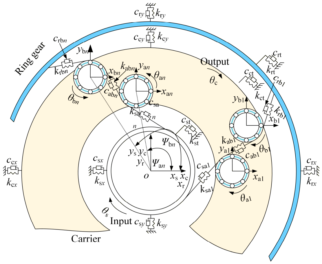
A dynamic model of the DPGT is shown in Figure 1. The model comprises a sun gear, a carrier, a ring gear, N inner planets, N outer planets, 2 × N × Z PB rollers, and 2 × N PB cages. Z is the number of PB rollers. Two coordinate systems are defined: (1) a fixed coordinate system with its origin at point O and (2) a rotating coordinate system attached to the carrier which has its origin at point O’. Each component has three degrees of freedom, including translational motion along the x-axis, translational motion along the y-axis, and rotational motion. The translational motions of the sun gear, carrier, and ring gear are described in the fixed coordinate system. The translational motions of the planet gears, cages, and rollers are described in the rotating coordinate system.
The dynamic equations of the sun gear are expressed as:
m s x ¨ s + c s x x ˙ s + k s x x s + n = 1 N F sa n cos ψ a n = m s x s Ω 2 + 2 m s y ˙ s Ω + m s y s Ω ˙
m s y ¨ s + c s y y ˙ s + k s y y s + n = 1 N F sa n sin ψ a n = m s y s Ω 2 2 m s x ˙ s Ω m s x s Ω ˙
J s r s θ ¨ s + n = 1 N F sa n = T i r s
where rs, ms, and Js denote the base radius, mass, and moment of inertia of the sun gear, respectively. xs, ys, and θs represent the translational displacements in the x- and y-directions and the rotational displacement of the sun gear, respectively. In the following, the subscripts s, r, an, bn, and abn represent the sun gear, ring gear, the nth inner planet, the nth outer planet, and the nth inner–outer planet, respectively. ksx, ksy, csx, and csy are the support stiffness and damping of the sun gear in the x- and y-directions, respectively. Ti is the input torque applied to the sun gear. Ω is the carrier rotation velocity. ψan is the angular position of the nth inner planet relative to the sun gear. Fsan is the meshing force between the sun gear and the nth inner planet, which can be expressed as:
F sa n = k sa n δ sa n + c sa n δ ˙ sa n
where ksan and csan are the mesh stiffness and damping of the nth sun–inner planet gear pair, respectively. The detailed calculation method is given in ref. [20]. δsan is the mesh deformation of the nth sun–inner planet gear pair.
The dynamic equations of the ring gear are expressed as:
m r x ¨ r + c r x x ˙ r + k r x x r + n = 1 N F rb n cos ψ rb n = m r x r Ω 2 + 2 m r y ˙ r Ω + m r y r Ω ˙
m r y ¨ r + c r y y ˙ r + k r y y r n = 1 N F rb n sin ψ rb n = m r y r Ω 2 2 m r x ˙ r Ω m r x r Ω ˙
J r r r θ ¨ r + c rt r r θ ˙ r + k rt r r θ r n = 1 N F rb n = 0
where krx, kry, crx, and cry are the support stiffness and damping of the ring gear in the x-and y-directions, respectively. krt and crt are the torsional support stiffness and damping of the ring gear, respectively. ψrbn is the angular position of the nth outer planet relative to the ring gear. Frbn is the nth outer planet–ring gear mesh force, which can be expressed as:
F rb n = k rb n δ rb n + c rb n δ ˙ rb n
where krbn and crbn are the nth outer planet–ring gear mesh stiffness and damping, respectively. δrbn is the nth outer planet–ring gear mesh deformation.
The dynamic equations of the nth inner planet are expressed as:
m a n x ¨ a n = m a n x a n Ω 2 + 2 m a n y ˙ a n Ω + m a n y a n Ω ˙ + m a n r c Ω 2 cos ψ a n + F a x o + F ad x o F ag x o + F sa n cos ψ a n F ab n cos ψ ab n
m a n y ¨ a n = m a n y a n Ω 2 2 m a n x ˙ a n Ω m a n x a n Ω ˙ + m a n r c Ω 2 sin ψ a n + F a y o + F ad y o F ag y o + F sa n sin ψ a n F ab n sin ψ ab n
J a n r a n θ ¨ a n + F sa n F ab n + M cage r a n + j = 1 Z f o j d m 2 r a n = 0
where dm is the PB pitch diameter. rc is the carrier base radius. ψabn is the angular position of the nth inner–outer planet. Mcage is the inner planet–cage friction moment. Fabn is the nth inner–outer planet mesh force. F a x o and F a y o represent the total forces for the nth inner planet–roller contact pairs in the x- and y-directions, respectively. F ag x o and F ag y o are the total forces for the nth inner planet–cage contact pairs in the x- and y-directions, respectively. F ad x o and F ad y o are the nth inner planet–roller damping forces in the x- and y-directions, respectively. The expressions for these forces are given as follows.
F ab n = k ab n δ ab n + c ab n δ ˙ ab n
F a x o = j = 1 Z Q o j cos θ j + f o j sin θ j
F a y o = j = 1 Z Q o j sin θ j + f o j cos θ j
F ad x o = j = 1 Z c o x ˙ e j x ˙ a n
F ad y o = J = 1 Z c o y ˙ e j y ˙ a n
where kabn and cabn are the nth inner–outer planet mesh stiffness and damping, respectively. co is the damping between the planet and the roller. xej and yej are the displacements of the jth roller in the x- and y-directions, respectively. θj is the jth roller position angle. δabn is the nth inner–outer planet mesh deformation. Qoj and foj are the PB roller–planet contact force and friction force, respectively [30,31], which are given by:
Q o j = ζ o j K o δ o j 10 9
f o j = μ Q o j
where Ko and μ are the roller–planet contact stiffness and friction coefficient, respectively [20]. ζoj is the jth roller–planet contact coefficient. δoj is the contact deformation as follows.
δ o j = x e j x a n cos θ j + y e j y a n sin θ j
The dynamic equations of the nth outer planet are expressed as:
m b n x ¨ b n = m b n x b n Ω 2 + 2 m b n y ˙ b n Ω + m b n y b n Ω ˙ + m b n r c Ω 2 cos ψ b n + F b x o + F bd x o F bg x o + F rb n cos ψ rb n + F ab n cos ψ ab n
m b n y ¨ b n = m b n y b n Ω 2 2 m b n x ˙ b n Ω m b n x b n Ω ˙ + m b n r bc Ω 2 sin ψ b n + F b y o + F bd y o F bg y o F rb n sin ψ rb n + F ab n sin ψ ab n
J r n r b n θ ¨ b n + F rb n F ab n + M cage r b n + j = 1 Z f bo j d m 2 r b n = 0
where F b x o and F b y o are the total contact forces of the nth outer planet–roller pairs in the x- and y-directions, respectively. F bg x o and F bg y o are the total contact forces of the nth outer planet–cage pairs in the x and y-directions, respectively. F bd x o and F bd y o are the nth outer planet gear–roller damping forces in the x- and y-directions, respectively. The expressions for these forces are given as follows.
F b x o = j = 1 Z Q o j cos θ j + f o j sin θ j
F b y o = j = 1 Z Q o j sin θ j + f o j cos θ j
F bd x o = j = 1 Z c o x ˙ e j x ˙ b n
F bd y o = j = 1 Z c o y ˙ e j y ˙ b n
The dynamic equations of the carrier are expressed as:
m c x ¨ c = m c x c Ω 2 + 2 m c y ˙ c Ω + m c y c Ω ˙ F x i F d x i c c x x ˙ c k c x x c
m c y ¨ c = m c y c Ω 2 2 m c x ˙ c Ω m c x c Ω ˙ F y i F d y i c c x y ˙ c k c x y c
J c r c θ ¨ c + n = 1 2 N F x i sin ψ n n = 1 2 N F y i cos ψ n = T 0 r c
where rc, mc, and Jc are the planet installation radius, carrier mass, and carrier moment of inertia, respectively. xc, yc, and θc are the translational displacements in the x- and y-directions and the rotational displacement of the carrier, respectively. F x i and F y i are the total contact forces of the carrier–roller pairs in the x- and y-direction, respectively. F d x i and F d y i are the carrier–roller damping forces in the x- and y-directions, respectively. The expressions for these forces are given as follows.
F x i = j = 1 Z Q i j cos θ j + f i j sin θ j
F y i = j = 1 Z Q i j sin θ j + f i j cos θ j
F d x i = j = 1 Z c i x ˙ c x ˙ e j
F d y i = j = 1 Z c i y ˙ c y ˙ e j
where ci is the roller–carrier damping. Qij and fij are the roller–carrier contact force and friction force.
Q i j = ζ i j K i δ i j 10 9
f i j = μ Q i j
where Ki is the roller–carrier contact stiffness. ζij is the roller–carrier contact coefficient, which is 1 when δij > 0 and is 0 when δij ≤ 0. δij is the roller–carrier contact deformation, which is expressed as follows:
δ i j = x c x e j cos θ j + y c y e j sin θ j C r
where Cr is the clearance.
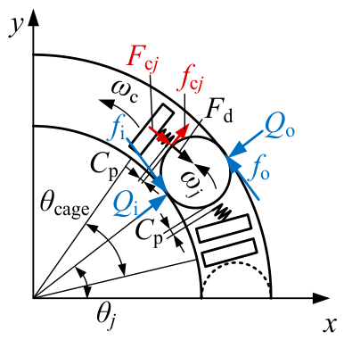
Figure 2 shows the force analysis of the PB rollers during motion. Fd is the flow resistance of the lubricant, Fcj is the collision force between the roller and the cage, and fcj is the frictional force between the roller and the cage.
The PB roller dynamic equations are expressed as:
m e x ¨ e j = Q o j cos θ j + Q i j cos θ j c o x ˙ e j x ˙ p + c i x ˙ c x ˙ e j + F c j sin θ j f c j sin θ j f o j sin θ j + f i j sin θ j + F c 1 cos ϕ c + F c 2 cos θ j + F d sin θ j
m e y ¨ e j = Q o j sin θ j + Q i j sin θ j c o y ˙ e j y ˙ p + c i y ˙ c y ˙ e j F c j cos θ j + f c j sin θ j + f o j cos θ j f i j cos θ j + F c 1 sin ϕ c + F c 2 sin θ j F d cos θ j
I e ϕ ¨ e j = F f o + F f i f c j D w 2
I ec θ ¨ e j = F f o R o F f i R i F c j d m 2 F d d m 2
where me is the mass of the PB roller. Ie is the moment of inertia around the roller axis of the PB roller. Iec is the PB roller moment of inertia about the PB axis. ϕe and θe are the roller angular displacements around its axis and PB axis, respectively. Fc1 and Fc2 are centrifugal forces about the DPGS axis and PB axis, respectively.
The cage dynamic equations are expressed as:
m g x ¨ g = F c j sin θ j f c j cos θ j + F c x
m g y ¨ g = F c j cos θ j f c j sin θ j + F c y G
I g θ ¨ g = M c + F c j d m 2
where mg and Ig are the mass and moment of inertia of the cage, respectively. xg, yg, and θg are the translational displacements in the x- and y-directions and the rotational displacement of the cage, respectively. G is the cage gravity.
Due to the presence of an oil–gas mixture composed of lubricating oil and gas inside the bearing cavity, which imposes resistance on the orbital motion of the rollers, the flow-around drag force of the lubricant is given by:
F d = 1 8 C d ρ D b l d m ω m 2
where Cd is the flow-around drag coefficient. ρ is the density of the oil–gas mixture. Db is the roller diameter. l is the roller length. dm is the pitch diameter of the PB. ωm is the orbital angular velocity of the rollers.
Based on the relative motion, the roller–cage collision force can be determined as:
F c j = K cage θ j θ g d m 2 C p θ j θ g > 0 F c j = K cage θ j θ g d m 2 + C p θ j θ g < 0
where Kcage is the roller–cage pocket contact stiffness. Cp is the cage pocket clearance.
The cage adopts an outer ring-guided configuration. In the planetary gear train, the planet gear serves as the outer ring of the bearing. Collision forces occur between the guide surface and the cage, which can be expressed as:
F c = K g e g C g + c g e ˙ g
where Cg is the guiding clearance of the cage. eg is the relative offset of the cage center, which is expressed as follows:
e g = x g 2 + y g 2
The proposed dynamic modeling approach is general and can be extended to other planetary gear configurations with minor modifications. Specifically, different planetary arrangements can be realized by adjusting the number of planet gears in the model. A single planetary gear set can be obtained by replacing the meshing force between the inner and outer planets in the dynamic equations with that between the planet gear and the ring gear. In addition, different power flow configurations can be represented by applying sufficiently large torsional stiffness to constrain selected components. In this way, the sun gear, carrier, or ring gear can be treated as fixed or output members, enabling the simulation of various transmission schemes. Therefore, the proposed framework is not limited to the specific DPGT configuration considered in this study, but can be readily extended to a wide range of planetary gears.


3. Experiment Verification

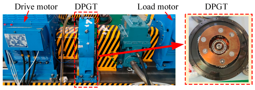
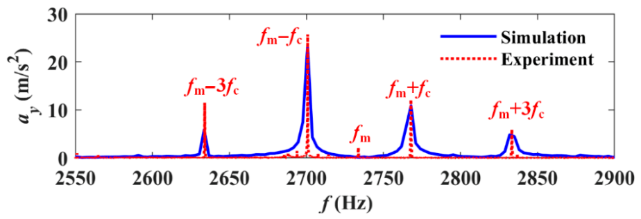
To validate the proposed dynamic model, a DPGT experimental platform was constructed, as illustrated in Figure 3. The driving motor is connected to the sun gear, while the loading motor is connected to the carrier to provide the system load. The vibrations of the DPGT are measured using an acceleration sensor mounted on the carrier bearing housing near the carrier axis. The parameters of the DPGT and PB are listed in Table 1 and Table 2, respectively. The rotation speeds of the sun gear and the carrier are 3290 r/min and 2000 r/min. A comparison between the simulation and experimental results is presented in Figure 4. Characteristic frequencies, including fm, fm ± fc, and fm ± 3fc (fm and fc denote the gear mesh frequency and carrier rotation frequency, respectively), are observed in both results. While a discrepancy in amplitude is observed at fm ± 3fc, the frequency locations are in good agreement. This difference is mainly attributed to factors not included in the model, such as structural flexibility, clearance, and misalignment. Despite these differences, the consistency in characteristic frequency distribution demonstrates that the proposed model is capable of capturing the essential dynamic behavior of the system, thereby validating the developed DPGT dynamic model.

4. Results and Discussion

4.1. Dynamic Load Analysis of Planetary Bearings

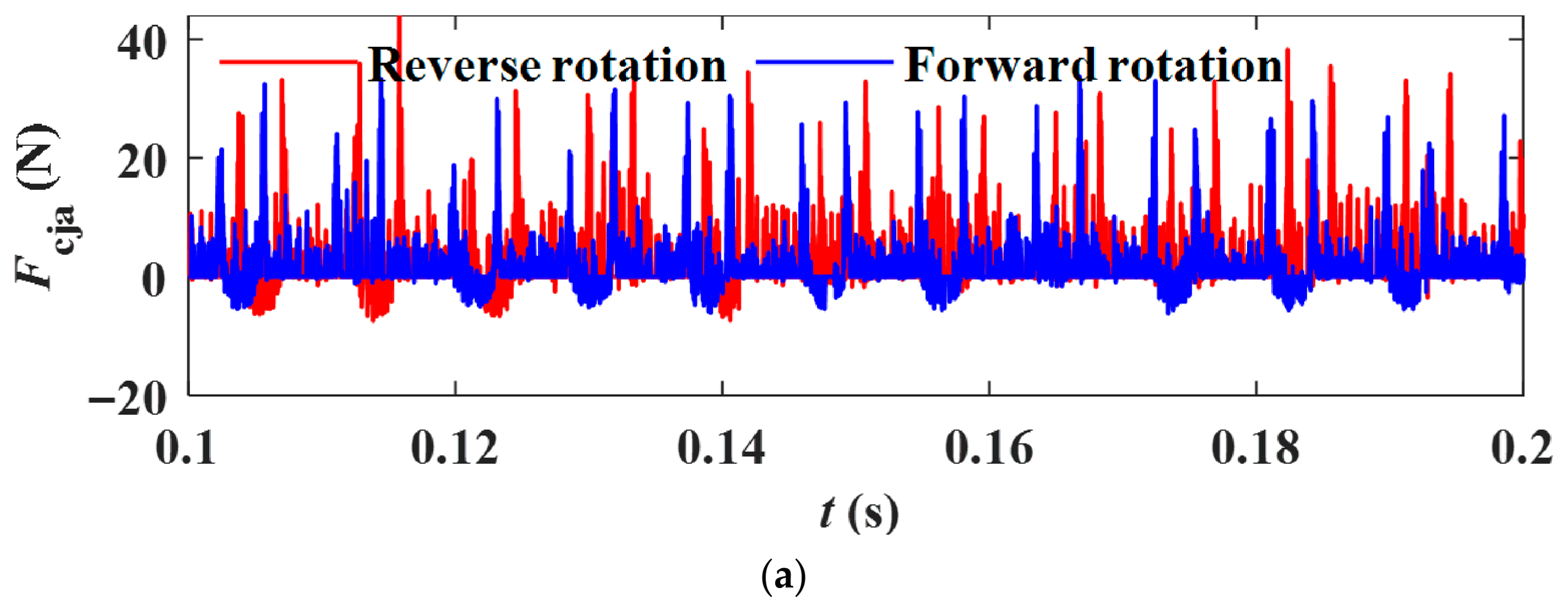
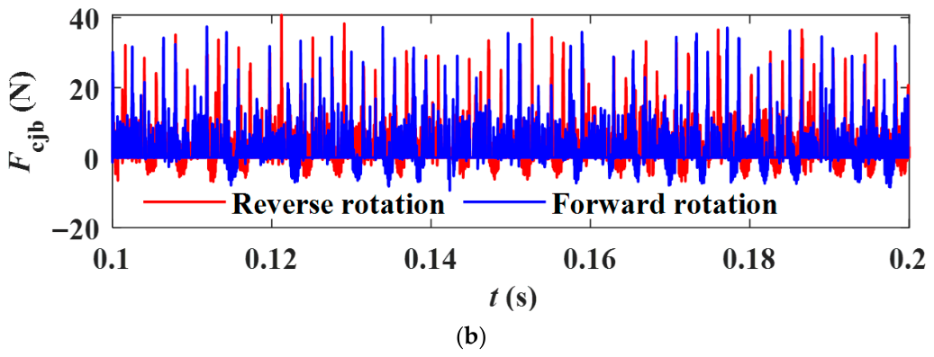
To analyze the dynamic loads of bearings, the power is set to 200 kW. The sun gear rotates at 6910 r/min, while the ring gear remains fixed. The carrier operates at 4200 r/min during forward rotation and −4200 r/min during reverse rotation. The collision forces between the PB roller and the cage are shown in Figure 5. For the inner PB, the RMS value of the roller–cage collision force is 4.29 N under forward rotation. In reverse rotation, it increases to 4.48 N, representing a 4.43% increase. For the outer PB, the RMS value is 4.76 N under forward rotation. In reverse rotation, it rises to 4.92 N, showing a 3.36% increase. The minimal variation observed suggests that the carrier rotation direction has a negligible impact on the roller–cage collision force. This phenomenon can be attributed to the fact that the collision energy between the cage and the roller remains nearly unchanged under the identical operating speed.
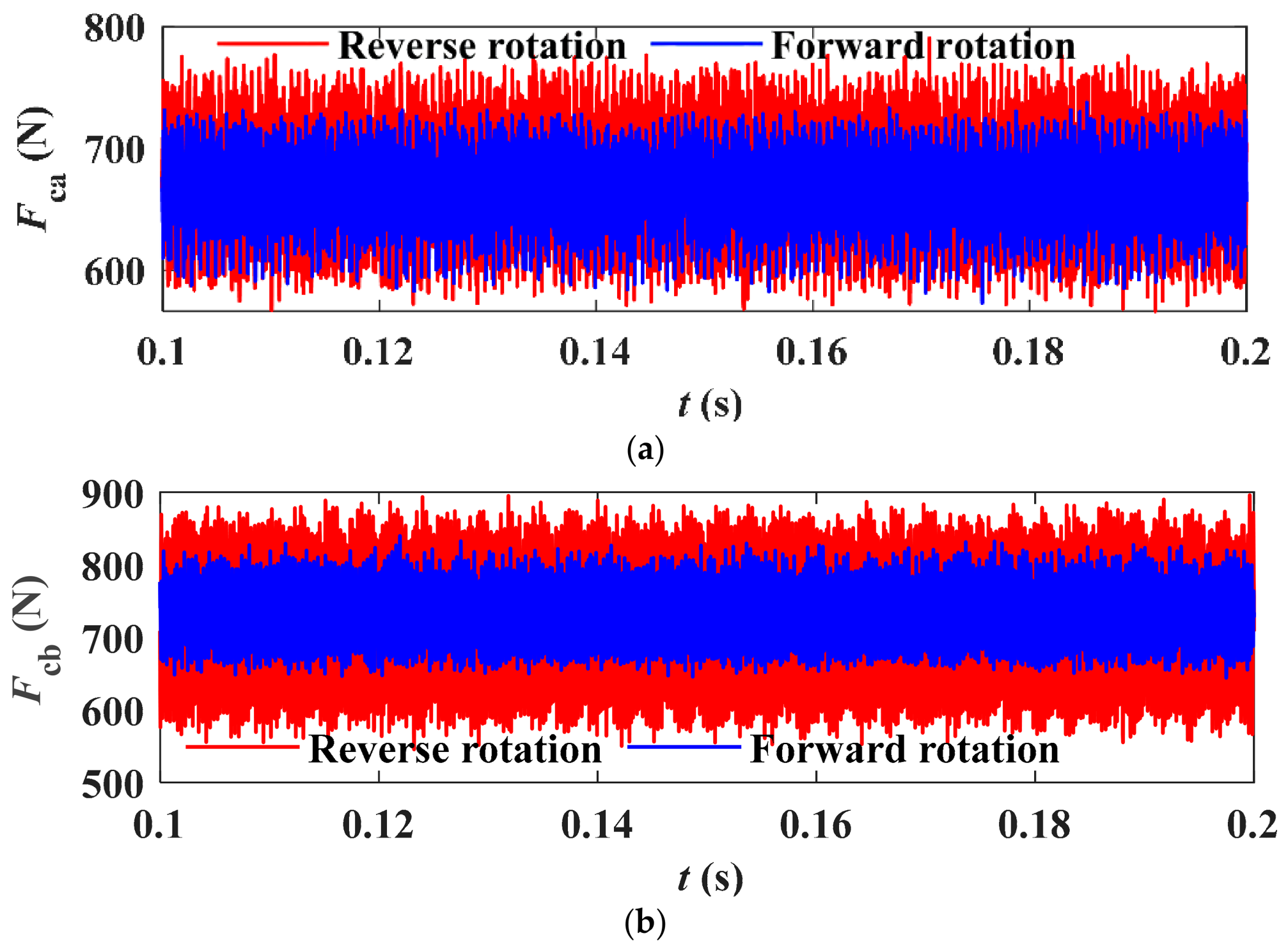
Figure 6 shows the collision forces between the cage and the guiding surface of the PBs. For the inner PB, the maximum collision force is 737.26 N, with an RMS value of 672.24 N under forward rotation of the carrier. In reverse rotation, the maximum collision force increases to 790.48 N, with an RMS value of 673.18 N. The maximum collision force increases by 7.22%, while the RMS value remained nearly unchanged. For the outer PB, the maximum collision force is 841.52 N, with an RMS value of 732.85 N under forward rotation. In reverse rotation, the maximum collision force increases to 902.05 N, with an RMS value of 740.27 N. The maximum collision force increased by 7.19%. The reason is that the change in rotation direction modifies the approach velocity between the cage and the guiding surface, thereby promoting more abrupt impact-type contacts.
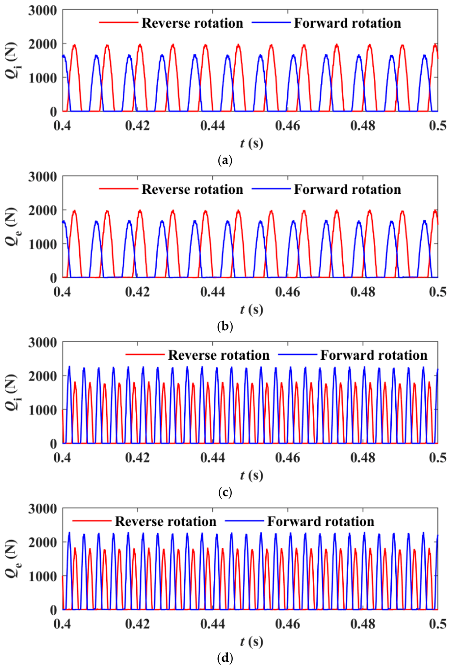
The PB contact forces under both forward and reverse rotations are shown in Figure 7. For the inner PB, the maximum roller–inner ring contact force increases from 1.6907 × 10³ N to 1.9969 × 10³ N under reverse rotation, corresponding to an 18.11% increase. A similar trend is observed for the roller–outer ring contact force, which rises from 1.702 × 10³ N to 2.0129 × 10³ N, representing an increase of 18.27%. According to ISO 281, the bearing life is proportional to the inverse cube of the equivalent dynamic load [32]. The basic rated life of the inner PB under reverse rotation is reduced by approximately 42.7% relative to forward rotation. This result confirms that the inner PB operates under substantially more severe contact loading conditions during reverse rotation, leading to a significantly elevated risk of contact fatigue failure. In contrast, for the outer PB, the maximum roller–inner ring contact force decreases from 2.29 × 10³ N to 1.8348 × 10³ N, showing a reduction of 19.88%. Likewise, the roller–outer ring contact force decreases from 2.3026 × 10³ N to 1.836 × 10³ N, corresponding to a 20.26% reduction. These results indicate that the inner PB experiences higher contact forces under reverse rotation, whereas the outer PB exhibits higher contact forces under forward rotation. This opposite trend can be attributed to the load redistribution induced by the change in carrier rotation direction.
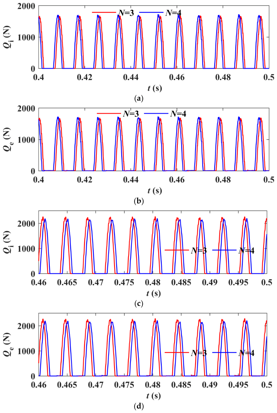
In addition, Figure 8 compares the PB contact forces under different numbers of planetary gears. For the inner PB, the RMS roller–inner ring contact force increases slightly from 0.76 × 10³ N to 0.78 × 10³ N when N = 3, corresponding to an 2.6% increase. A similar trend is observed for the roller–outer ring contact force, which rises marginally from 0.77 × 10³ N to 0.78 × 10³ N, representing an increase of 1.2%. In contrast, for the outer PB, both contact forces exhibit a slight reduction. The RMS roller–inner ring contact force decreases from 1.03 × 10³ N to 0.99 × 10³ N (3.8% reduction), while the roller–outer ring contact force decreases from 1.04 × 10³ N to 1.00 × 10³ N, also corresponding to a 3.8% reduction. These results indicate that the number of planetary gears has a limited influence on the bearing contact loads.

To analyze the influence of operating conditions on the dynamic load of the PB, four conditions are established as follows:
Condition 1: carrier speed of 1000 r/min with an output power of 200 kW.
Condition 2: carrier speed of 2000 r/min with an output power of 200 kW.
Condition 3: carrier speed of 4200 r/min with an output power of 200 kW.
Condition 4: carrier speed of 4200 r/min with zero output power.
Table 3 summarizes the RMS values of the roller–cage collision force under the four conditions. In all cases, the collision force under reverse carrier rotation is consistently higher than that under forward rotation. This discrepancy is most pronounced under low-speed, high-torque conditions (Condition 1), where the inner and outer PBs exhibit differences of 38.34% and 31.25%, respectively. This result demonstrates that the roller–cage interaction is highly sensitive to the carrier rotation direction under severe loading conditions. Regardless of rotation direction, the outer PB consistently exhibits higher collision forces than the inner PB. This can be attributed to centrifugal inertial effects. The outer PB is located farther from the rotation center and is therefore subjected to larger centrifugal forces, which intensify the dynamic interaction between the roller and the cage.
Table 4 presents the RMS values of the cage–guiding surface collision force. Similar to the roller–cage interaction, reverse carrier rotation results in higher collision forces than forward rotation. This effect is particularly significant in Condition 2, where the collision force increases by 15.93% for the outer PB and 4.71% for the inner PB. In contrast, under Condition 4, the difference between forward and reverse rotation becomes negligible. This indicates that the influence of rotation direction on cage guidance diminishes in the absence of load. Overall, these results demonstrate that reverse rotation intensifies cage–guiding surface impacts under loaded conditions, while the outer PB is more susceptible to collision-induced wear due to its higher dynamic loads.
Table 5 and Table 6 compare the RMS values of the roller–inner ring and roller–outer ring contact forces, respectively. The contact loads exhibit a strong dependency on the carrier rotation direction. For the inner PB, reverse rotation leads to increased contact forces, whereas the outer PB experiences higher loads under forward rotation. In addition, at a given power of 200 kW, the contact load of the PBs first decreases and then increases with rotational speed. This indicates that mesh forces dominate the contact load at low speeds, whereas centrifugal forces become the primary contributor as the rotational speed increases. Under no-load conditions, the difference in contact loads between forward and reverse rotations becomes negligible. This suggests that mesh forces are the primary factor responsible for the discrepancy in contact loads under opposite rotation directions. The increase in contact force under reverse rotation not only accelerates fatigue damage, but also has important implications for thermal behavior. Previous studies have shown that thermal effects play a critical role in bearing performance. Wang [33] demonstrated that increasing rotational speed significantly influences thermoelastohydrodynamic behavior, altering load distribution and lubricant film thickness. Lee et al. [34] further indicated that thermal effects are closely coupled with rotor dynamic stability. Li et al. [35] experimentally showed that rotor vibration characteristics are closely related to thermal and lubrication states. These findings are highly relevant to DPGT systems, where high rotational speeds and complex load coupling can exacerbate thermal instability. In the present study, the observed increase in contact force and vibration under reverse rotation may intensify frictional heat generation, thereby degrading lubrication conditions and accelerating bearing wear.

4.2. Vibration Analysis of Planetary Bearings

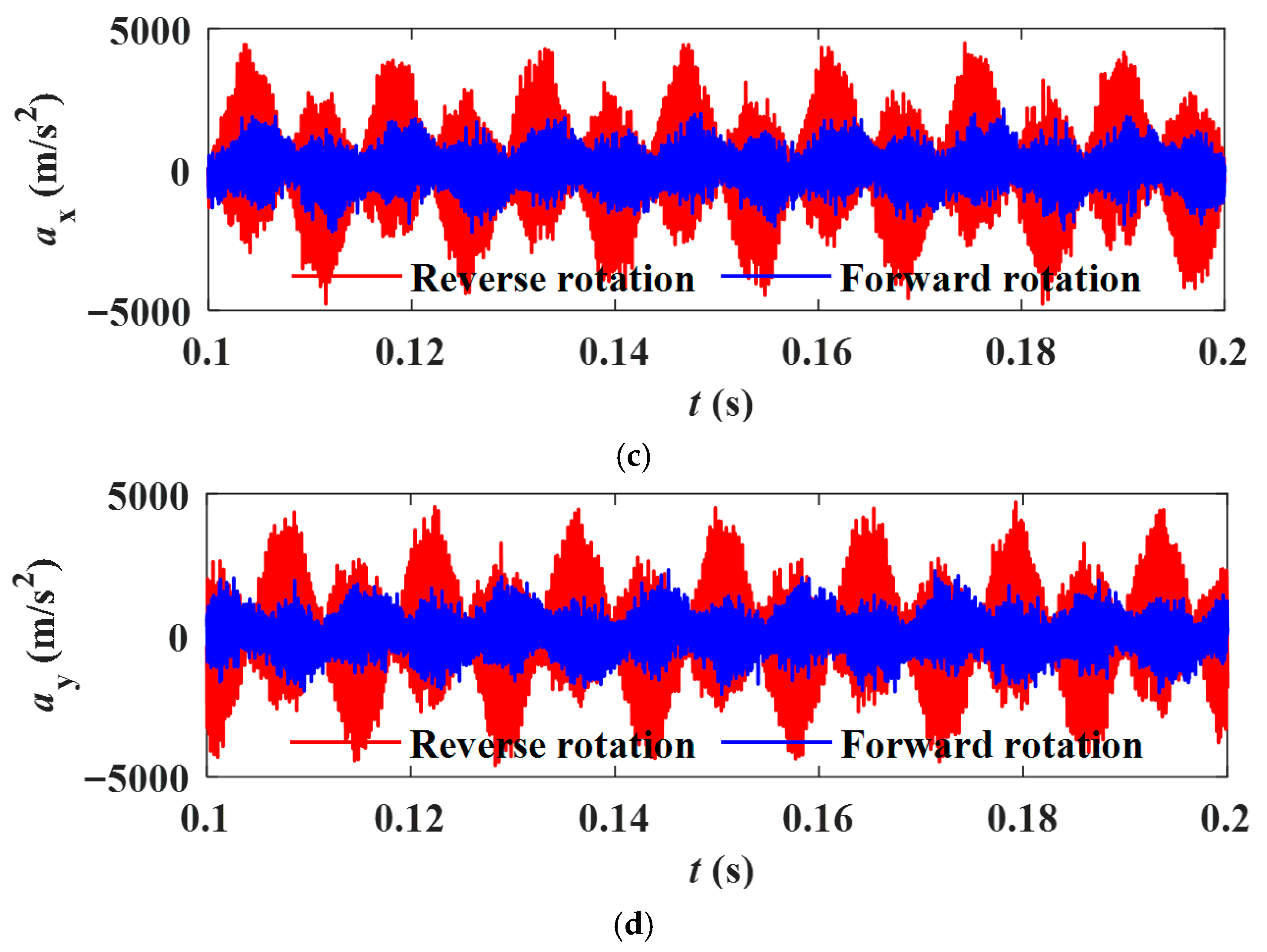
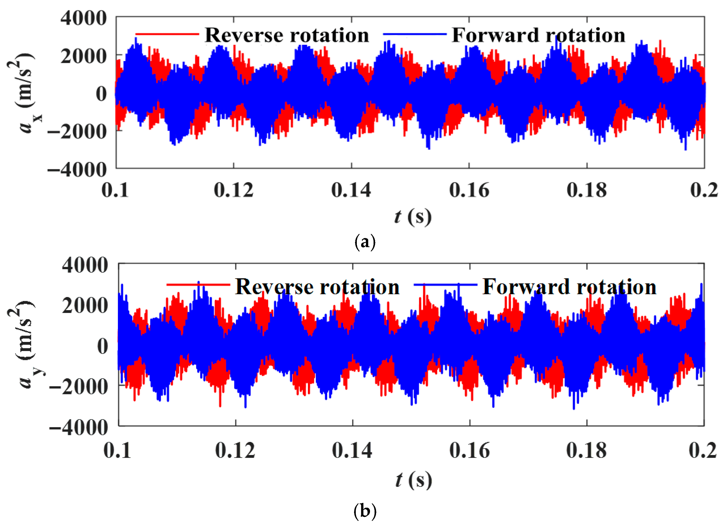
Figure 9 illustrates the vibration response of the PB cage under both forward and reverse carrier rotation conditions. For the inner PB cage, the RMS acceleration in the x-direction increases from 711.26 m/s2 under forward rotation to 899.50 m/s2 under reverse rotation, representing a 26.47% rise. A similar trend is observed in the y-direction, where the value rises from 707.68 m/s2 to 894.33 m/s2, representing a 26.73% rise. In contrast, the outer PB cage exhibits a much stronger amplification under reverse rotation. The RMS acceleration in the x-direction increases from 824.65 m/s2 to 1618.00 m/s2, representing a 96.20% rise, while in the y-direction it increases from 824.22 m/s2 to 1613.30 m/s2, representing a 95.74% rise. These results demonstrate a clear directional dependence of the vibration response on the carrier rotation direction, with the outer PB showing significantly higher sensitivity than the inner PB.
Table 7 and Table 8 summarize the RMS vibration acceleration of the PB cages. The vibration acceleration is generally lower under forward rotation than under reverse rotation. An exception occurs at 200 kW and 2000 r/min, where the inner PB cage exhibits higher vibration acceleration under forward rotation. In addition, the outer PB cage shows greater sensitivity to the carrier rotation direction than the inner PB cage. Under the no-load conditions, the difference in vibration acceleration between forward and reverse rotation is significantly smaller than that under loaded conditions. This indicates that input power is the primary factor governing the rotation-induced variation in vibration response.

5. Conclusions

This study developed a dynamic model of the DPGT, incorporating the sun gear, inner and outer planets, ring gear, carrier, PB rollers, and PB cages. The dynamic loads and vibration responses of the PBs under forward and reverse carrier rotations are analyzed. The results indicate that the change in rotation direction leads to significant asymmetric loading of the PBs. This asymmetric loading behavior requires targeted modifications to the bearing lubrication system. In addition, heavily loaded bearing components under specific rotation directions should use materials with higher contact fatigue resistance. The initial assumption, namely that carrier forward and reverse rotations lead to significant differences in PB dynamic load and vibration responses, is fully confirmed by the obtained results. The main conclusions are given as follows:
(1)
Reverse carrier rotation increases the collision forces between the rollers and the cage, as well as between the cage and the guiding surface. This effect becomes more pronounced under low-speed and high-torque conditions. This indicates that an appropriate selection of carrier rotational direction can help mitigate failure risk.
(2)
The inner PB exhibits higher contact loads under reverse rotation, whereas the outer PB experiences higher loads under forward rotation. At constant power, the influence of rotational direction on the bearing contact load first increases and then decreases with increasing speed. Therefore, the outer or inner PB should be prioritized based on the carrier rotational direction and the typical operating speed.
(3)
Reverse carrier rotation significantly amplifies cage vibrations, particularly in the outer PB. At constant power, the influence of rotational direction on cage vibration increases with speed, while it becomes negligible under no-load conditions. This suggests that vibration control strategies should primarily focus on loaded operating conditions.
Future work may explore advanced lubricants to address asymmetric bidirectional lubrication requirements, such as lower viscosity for forward rotation, higher viscosity or stronger film for reverse rotation. Active rheological control may help compensate for rotation-induced load asymmetry without major structural modifications.

Author Contributions

Conceptualization, K.L., L.Y., J.Z., R.M. and H.S.; Methodology, Y.Z.; Validation, Y.Z.; Formal analysis, Y.Z.; Investigation, Y.Z. and B.M.; Resources, L.Y. and R.M.; Writing—original draft, Y.Z.; Writing—review & editing, Y.Z., K.L., R.M. and H.S.; Visualization, B.M.; Supervision, L.Y., J.Z. and H.S.; Project administration, L.Y.; Funding acquisition, L.Y. All authors have read and agreed to the published version of the manuscript.

Funding

This research received no external funding.

Data Availability Statement

Data are contained within the article.

Conflicts of Interest

The authors declare no conflict of interest.

References

  1. Stanojević, M.; Tomović, R.; Ivanović, L.; Stojanovic, B. Critical analysis of design of Ravigneaux planetary gear trains. Appl. Eng. Lett. 2022, 7, 32–44. [Google Scholar] [CrossRef]
  2. Liu, C.; Yin, X.; Liao, Y.; Yi, Y.; Qin, D. Hybrid dynamic modeling and analysis of the electric vehicle planetary gear system. Mech. Mach. Theory 2020, 150, 103860. [Google Scholar] [CrossRef]
  3. Luo, W.; Qiao, B.; Shen, Z.; Yang, Z.; Cao, H.; Chen, X. Investigation on the influence of spalling defects on the dynamic performance of planetary gear sets with sliding friction. Tribol. Int. 2021, 154, 106639. [Google Scholar] [CrossRef]
  4. Hammami, A.; Mbarek, A.; Fernández, A.; Chaari, F.; Viadero, F.; Haddar, M. Dynamic behavior of the nonlinear planetary gear model in nonstationary conditions. Mech. Eng. Sci. 2021, 235, 4648–4662. [Google Scholar] [CrossRef]
  5. Shen, Z.; Qiao, B.; Yang, L.; Luo, W.; Yang, Z.; Chen, X. Fault mechanism and dynamic modeling of planetary gear with gear wear. Mech. Mach. Theory 2021, 155, 104098. [Google Scholar] [CrossRef]
  6. Ryali, L.; Talbot, D. A dynamic load distribution model of planetary gear sets. Mech. Mach. Theory 2021, 158, 104229. [Google Scholar] [CrossRef]
  7. Hu, J.; Hu, N.; Yang, Y.; Zhang, L.; Shen, G. Nonlinear dynamic modeling and analysis of a helicopter planetary gear set for tooth crack diagnosis. Measurement 2022, 198, 111347. [Google Scholar] [CrossRef]
  8. Dai, H.; Wang, Y.; Luo, S.; Li, Y.; Zi, B. Dynamic modeling and vibration analysis of planetary gear sets concerning mesh phasing modulation. Mech. Syst. Signal Process. 2023, 200, 110557. [Google Scholar] [CrossRef]
  9. Yang, Y.; Hu, N.; Li, Y.; Cheng, Z.; Shen, G. Dynamic modeling and analysis of planetary gear system for tooth fault diagnosis. Mech. Syst. Signal Process. 2024, 207, 110946. [Google Scholar] [CrossRef]
  10. Xu, Z.; Yu, W.; Shao, Y.; Yang, X.; Nie, C.; Peng, D. Dynamic modeling of the planetary gear set considering the effects of positioning errors on the mesh position and the corner contact. Nonlinear Dyn. 2022, 109, 1551–1569. [Google Scholar] [CrossRef]
  11. Wang, P.; Xu, H.; Ma, H.; Han, H.; Yang, Y. Effects of three types of bearing misalignments on dynamic characteristics of planetary gear set-rotor system. Mech. Syst. Signal Process. 2022, 169, 108736. [Google Scholar] [CrossRef]
  12. Luo, W.; Qiao, B.; Shen, Z.; Yang, Z.; Cao, H.; Chen, X. Influence of sliding friction on the dynamic characteristics of a planetary gear set with the improved time-varying mesh stiffness. J. Mech. Des. 2020, 142, 073302. [Google Scholar] [CrossRef]
  13. Zhang, C.; Yu, W.; Zhang, Y.; Xu, J.; Zeng, Q.; Li, L.; Wang, L.; Huang, W. Dynamics modeling and analysis of the multistage planetary gear set-bearing-rotor-clutch coupling system considering the tooth impacts of clutches. Mech. Syst. Signal Process. 2024, 214, 111365. [Google Scholar] [CrossRef]
  14. Öztürk, V.; Cigeroglu, E.; Özgüven, H. Ideal tooth profile modifications for improving nonlinear dynamic response of planetary gear trains. J. Sound Vib. 2021, 500, 116007. [Google Scholar] [CrossRef]
  15. Bai, Z.; Ning, Z. Dynamic responses of the planetary gear mechanism considering dynamic wear effects. Lubricants 2023, 11, 255. [Google Scholar] [CrossRef]
  16. Wei, J.; Zhang, A.; Shi, L.; Qin, D. Modeling and dynamic characteristics of planetary gear transmission in non-inertial system of aerospace environment. J. Mech. Des. 2020, 142, 031103. [Google Scholar] [CrossRef]
  17. Tan, J.; Hao, L.; Hao, T.; Zhu, C.; Song, C.; Dong, Y.; Sun, Z. Dynamic modeling and analysis of planetary gear train system considering structural flexibility and dynamic multi-teeth mesh process. Mech. Mach. Theory 2023, 186, 105348. [Google Scholar] [CrossRef]
  18. Zhang, M.; Zuo, M.J.; Wei, D.; Liu, J.; Wang, K.; Wang, Y. Motion periods of sun gear dynamic fault meshing positions in planetary gear systems. Measurement 2020, 162, 107897. [Google Scholar] [CrossRef]
  19. Sang, M.; Huang, K.; Xiong, Y.; Han, G.; Cheng, Z. Dynamic modeling and vibration analysis of a cracked 3K-II planetary gear set for fault detection. Mech. Sci. 2021, 12, 847–861. [Google Scholar] [CrossRef]
  20. Liu, J.; Li, X.; Xia, M. A dynamic model for the planetary bearings in a double planetary gear set. Mech. Syst. Signal Process. 2023, 194, 110257. [Google Scholar] [CrossRef]
  21. Lai, J.; Liu, Y.; Xu, X.; Li, H.; Xu, J.; Wang, S.; Guo, W. Dynamic modeling and analysis of Ravigneaux planetary gear set with unloaded floating ring gear. Mech. Mach. Theory 2022, 170, 104696. [Google Scholar] [CrossRef]
  22. Li, X.; Liu, J.; Xu, J.; Chen, Y.; Hu, Z.; Pan, G. A vibration model of a planetary bearing system considering the time-varying wear. Nonlinear Dyn. 2023, 111, 19817–19840. [Google Scholar] [CrossRef]
  23. Li, X.; Liu, J.; Xu, Y.; Zhang, Y.; Liu, J.; Pan, G. Dynamic forces and vibrations of the planetary gear-set radial bearings with the roller dimension deviation. Int. J. Struct. Stab. Dyn. 2024, 26, 2550255. [Google Scholar] [CrossRef]
  24. Cheng, Y.; Liu, Y.; Zhang, Q. Vibration analysis of a double-row planetary gear set considering the sun gear axial position. Sci. Prog. 2024, 107, 00368504241275402. [Google Scholar] [CrossRef]
  25. Liu, J.; Ding, S.; Wang, L.; Li, H.; Xu, J. Effect of the bearing clearance on vibrations of a double-row planetary gear system. Proc. Inst. Mech. Eng. Part K J. Multi-Body Dyn. 2020, 234, 347–357. [Google Scholar] [CrossRef]
  26. Benford, H.; Leising, M. The lever analogy: A new tool in transmission analysis. SAE Trans. 1981, 90, 429–437. [Google Scholar]
  27. Syed, S.; Lhomme, W.; Bouscayrol, A.; Pape, O.; LeTrouher, G. Modeling of power split device for heavy-duty vehicles. In Proceedings of the IEEE Vehicle Power and Propulsion Conference, Lille, France, 1–3 September 2010; pp. 1–6. [Google Scholar]
  28. Zanasi, R.; Tebaldi, D. Modeling of complex planetary gear sets using power-oriented graphs. IEEE Trans. Veh. Technol. 2020, 69, 14470–14483. [Google Scholar] [CrossRef]
  29. Tebaldi, D.; Zanasi, R. Systematic modeling of complex time-variant gear systems using a power-oriented approach. Control Eng. Pract. 2023, 132, 105420. [Google Scholar] [CrossRef]
  30. Li, X.; Xu, Y.; Liu, J.; Zhang, Y.; Liu, J.; Pan, G.; Shi, Z. Vibration analysis of the propulsion shaft system considering dynamic misalignment in the outer ring. J. Sound Vib. 2024, 589, 118612. [Google Scholar] [CrossRef]
  31. Li, X.; Liu, J.; Ding, S.; Xu, Y.; Zhang, Y.; Xia, M. Dynamic modeling and vibration analysis of double row cylindrical roller bearings with irregular-shaped defects. Nonlinear Dyn. 2024, 112, 2501–2521. [Google Scholar] [CrossRef]
  32. ISO 281:2007; Rolling Bearings—Dynamic Load Ratings and Rating Life. International Organization for Standardization: Geneva, Switzerland, 2007.
  33. Wang, R.; Zhang, L. Effect of rotational speed on transient thermoelastohydrodynamic tribo-dynamic characteristics of journal bearings. Proc. Inst. Mech. Eng. Part J J. Eng. Tribol. 2025, 239, 597–618. [Google Scholar] [CrossRef]
  34. Lee, J.; Lee, J.; Suh, J.; Kim, J. Tilting-pad journal bearing design considering rotordynamic stability and bearing performance. Mech. Sci. Technol. 2025, 39, 1–12. [Google Scholar] [CrossRef]
  35. Li, S.; Luo, Y.; Shutin, D.; Kazakov, Y.; Sytin, A.; Liu, Y.; Zeng, Z.; Chen, Z.; Savin, L. Experimental study of rotor vibrations on oil-lubricated foil bearings of various designs. J. Vib. Eng. Technol. 2024, 12, 1119–1143. [Google Scholar] [CrossRef]
Figure 1. Dynamic model of the DPGT.
Machines 14 00539 g001
Figure 2. Dynamic model of the PB.
Machines 14 00539 g002
Figure 3. Experimental platform for the DPGT.
Machines 14 00539 g003
Figure 4. Simulated and experimental result comparison.
Machines 14 00539 g004
Figure 5. Roller–cage collision forces of PBs: (a) inner PB; (b) outer PB.
Machines 14 00539 g005aMachines 14 00539 g005b
Figure 6. Cage–guiding surface collision forces of PBs: (a) inner PB; (b) outer PB.
Machines 14 00539 g006
Figure 7. Contact forces of PBs: (a) inner PB roller–inner ring; (b) inner PB roller–outer ring; (c) outer PB roller–inner ring; (d) outer PB roller–outer ring.
Machines 14 00539 g007
Figure 8. Contact forces of PBs under different numbers of planetary gears: (a) inner PB roller–inner ring; (b) inner PB roller–outer ring; (c) outer PB roller–inner ring; (d) outer PB roller–outer ring.
Machines 14 00539 g008
Figure 9. Vibration of PB cages: (a) inner PB cage vibrations in x-directions; (b) Inner PB cage vibrations in y-directions; (c) outer PB cage vibrations in x-directions; (d) outer PB cage vibrations in y-directions.
Machines 14 00539 g009aMachines 14 00539 g009b
Table 1. Parameters of the DPGT.
Sun GearInner PlanetOuter PlanetRing GearCarrier
Modulus (mm)3333-
Tooth number31242482-
Pressure angle (°)20202020-
Tooth width (mm)35.5323233-
Mass (kg)1.0880.5570.5576.077.751
Table 2. Parameters of the PB.
Pitch Diameter (mm)Roller Diameter (mm)Roller Length (mm)Roller Number
397.5912
Table 3. RMS values of roller–cage collision force.
ConditionInner PB/NOuter PB/N
Forward RotationReverse RotationDifferenceForward RotationReverse RotationDifference
11.12651.558438.34%1.44721.899531.25%
21.09251.13153.57%1.28042.9518130.54%
34.294.484.43%4.764.923.36%
44.174.180.24%4.654.59−1.29%
Table 4. RMS values of cage–guiding surface collision force.
ConditionInner PB/NOuter PB/N
Forward RotationReverse RotationDifferenceForward RotationReverse RotationDifference
195.5197.942.54%109.72125.9914.83%
2183.77192.424.71%204.03236.5415.93%
3672.24673.180.14%732.85740.271.01%
4670.72670.58−0.02%730.67730.700.0041%
Table 5. RMS values of roller–inner ring contact force.
ConditionInner PB/NOuter PB/N
Forward RotationReverse RotationDifferenceForward RotationReverse RotationDifference
1335.58455.5435.75%986.36930.87−5.63%
2112.94373.97231.12%602.5373.97−37.93%
3760.54910.3419.70%1034.5812.43−21.47%
4835.03833.75−0.15%903.85904.240.043%
Table 6. RMS values of roller–outer ring contact force.
ConditionInner PB/NOuter PB/N
Forward RotationReverse RotationDifferenceForward RotationReverse RotationDifference
1359.79484.7734.74%1001.3955.98−4.53%
2142.28381.19167.92%617.34421.49−31.72%
3768.53918.5919.53%1041.2818.01−21.44%
4839.26838.57−0.082%910.77907.42−0.37%
Table 7. RMS values of cage vibration acceleration in the x-direction.
ConditionInner PB/(m/s2)Outer PB/(m/s2)
Forward RotationReverse RotationDifferenceForward RotationReverse RotationDifference
11542.915943.31%1811.12108.316.41%
21870.81798.7−3.85%19783256.764.65%
3711.26899.526.47%824.65161896.20%
4342.68354.643.49%398.28436.89.67%
Table 8. RMS values of cage vibration acceleration in the y-direction.
ConditionInner PB/(m/s2)Outer PB/(m/s2)
Forward RotationReverse RotationDifferenceForward RotationReverse RotationDifference
11551.21608.13.67%1787.52094.517.17%
21861.41797.6−3.431988.23270.664.50%
3707.68894.3326.37%824.221613.395.74%
4345.7354.252.47%400.39437.099.17%
Disclaimer/Publisher’s Note: The statements, opinions and data contained in all publications are solely those of the individual author(s) and contributor(s) and not of MDPI and/or the editor(s). MDPI and/or the editor(s) disclaim responsibility for any injury to people or property resulting from any ideas, methods, instructions or products referred to in the content.