Article

The Influence of Non-Oriented Silicon Steel Core Material on Motor Performance

1
School of Automation, Beijing Institute of Technology, Beijing 100081, China
2
Shougang Zhixin Electromagnetic Material (Qian’an) Co., Ltd., Tangshan 064400, China
3
Department of Intelligent Control, Yantai Engineering & Technology College, Yantai 264006, China
*
Author to whom correspondence should be addressed.
Machines 2026, 14(5), 538; https://doi.org/10.3390/machines14050538
Submission received: 15 April 2026 / Revised: 5 May 2026 / Accepted: 9 May 2026 / Published: 11 May 2026

Abstract

Interior permanent magnet synchronous motors (IPMSMs) offer performance advantages such as saliency effect, high mechanical strength, and a wide speed regulation range. The magnetic and mechanical properties of the core material significantly influence IPMSM performance. By investigating the effects of different core materials on IPMSM performance, an optimal material combination can be identified to enhance the overall motor performance. This paper takes a V ¯ -shaped IPMSM for use as a main drive motor in new energy vehicles as the research object. First, the influence of the iron loss characteristics of non-oriented silicon steel (NOSS) on IPMSM performance is analyzed, and the material selection principles for the stator and rotor cores under this condition are summarized. Subsequently, the influence of the magnetic flux density characteristics of NOSS on IPMSM performance is analyzed, and the corresponding material selection principles for the stator and rotor cores are summarized. Furthermore, ultra-high-yield-strength NOSS is applied as the motor core material to reduce the width of the rotor magnetic flux barrier, and the resulting performance advantages for the IPMSM are analyzed. Finally, prototypes of the IPMSM are manufactured and tested to validate the results of the analysis.

1. Introduction

With the increasing demand for high-efficiency and high-reliability motors in modern industry, permanent magnet synchronous motors (PMSMs) are gradually becoming one of the most widely used motor types with the greatest market and industrial value due to their high power density, high efficiency, and excellent controllability. This is particularly evident in emerging productivity sectors such as new energy vehicles, electric vertical take-off and landing (eVTOL) aircraft, and robotics [1,2,3,4,5]. According to the installation position of the rotor permanent magnets, PMSMs can be classified into two major categories: surface-mounted PMSMs (SPMSMs) and interior PMSMs (IPMSMs). IPMSMs, offering advantages such as saliency effect, high mechanical strength, and a wide speed regulation range, have become the mainstream solution for drive motors in new energy vehicles [6,7].
The optimization of IPMSM performance can be approached from aspects such as motor structure and core material properties [8,9,10,11]. The rotor core of an IPMSM features a magnetic flux barrier structure, the strength of which must be sufficient to withstand the centrifugal stress generated during high-speed rotation. Therefore, the core material for IPMSMs is required to possess favorable iron loss and magnetic flux density characteristics in terms of magnetic properties, as well as adequate yield strength and tensile strength in terms of mechanical properties. Improvements in magnetic and mechanical properties rely on advanced production equipment, precise process control, and high-level technological research and development, which undoubtedly increase the manufacturing cost of the material. In practical applications, differentiated selection must be made based on the specific operating conditions and performance requirements of the IPMSM. Consequently, comprehensive research on the core materials and structure of IPMSMs holds significant theoretical value and practical significance. Focusing on soft magnetic materials such as silicon steel and amorphous alloys, domestic and international scholars have conducted extensive research from several perspectives, including iron loss characteristics, magnetic induction characteristics, processing techniques, and high-speed mechanical properties.
Iron loss is a major source of loss in PMSMs during high-speed operation, directly affecting efficiency and temperature rise. Current research focuses on reducing iron loss and achieving accurate modeling. Ultra-thin non-oriented silicon steel (NOSS) and silicon steel with high silicon content (6.5% Si) have become the mainstream choices for cores of high-speed PMSMs for vehicles. Studies have shown that ultra-thin silicon steel can significantly reduce eddy current loss, while silicon steel with high silicon content exhibits a lower degree of iron loss degradation under the coupling effect of temperature and compressive stress, making it suitable for scenarios demanding high operational stability [12]. Reference [13] systematically compares the differences in iron loss of silicon steel from different thicknesses and manufacturers, providing a basis for graded selection of motor core materials.
For high-power-density PMSMs pursuing higher electromagnetic loads, the Bs, knee point characteristics, and permeability under high magnetic flux of the core material have become research focuses. Using a soft magnetic alloy core with high Bs, combined with a lightweight stator structure, can significantly improve the power density of PMSMs, breaking through the upper limit of the magnetic load of traditional silicon steel [14]. Reference [15] establishes a three-step optimization design process based on saturated magnetic circuits to achieve synergistic optimization of efficiency and power density. By reasonably utilizing deep saturation of the core, the power density can be increased by more than 20% while keeping the total loss unchanged. Reference [16] indicates that manufacturing processes such as cutting, welding, stacking, and annealing can lead to degradation of the core’s magnetic properties. Self-bonding silicon steel, replacing traditional welding processes, achieves optimal magnetic performance under a stacking pressure of 3 MPa, reducing the additional loss caused by processing.
The rotor of a high-speed PMSM is subjected to immense centrifugal force, and the mechanical properties of the material directly determine its safety and reliability. Reference [17] reveals the coupling relationship between rotor vibration and mechanical stress in ultra-high-speed motors, providing a basis for rotor vibration reduction and strength design. Reference [18] proposes a novel layered composite rotor using composite magnetic materials, whose tensile strength far exceeds that of traditional permanent magnets. This study also establishes analytical stress equations and a critical speed calculation method, balancing electromagnetic performance and mechanical safety.
Considering both the magnetic and mechanical properties of silicon steel materials, and targeting application scenarios such as traction, aviation, and high-speed industrial drives, some scholars have developed material selection frameworks: interior PMSMs and conventional silicon steel are preferred for low-speed regions; amorphous alloys are preferred for high-speed, high-frequency regions; and rare-earth-free electrically excited synchronous motors can be adopted for cost-effectiveness and environmental friendliness [19,20].
However, research gaps remain in areas such as the basis for selecting stator and rotor materials for IPMSMs and application schemes for ultra-high-strength NOSS. This paper takes a V ¯ -shaped IPMSM for use as a main drive motor in new energy vehicles as the research object. First, the influence of NOSS iron loss on IPMSM performance is analyzed and introduced. Second, the influence of NOSS magnetic flux density on IPMSM performance is analyzed. Furthermore, the advantages of applying ultra-high-yield-strength NOSS to IPMSMs are also analyzed. By investigating the effects of different core material characteristics on IPMSM performance, this paper summarizes the selection principles for core materials to enhance the overall motor performance. Finally, taking a V ¯ -shaped IPMSM as an example, a prototype is manufactured and experimentally tested to validate the accuracy of the simulation analyses throughout the paper.

2. Research on the Influence of NOSS Iron Loss on IPMSM Performance

Iron loss is the most important performance indicator of NOSS, as it directly reflects the level of energy loss of the material under an alternating magnetic field, determining the efficiency and energy-saving performance of electrical equipment such as motors and transformers. Low iron loss not only significantly reduces energy consumption during equipment operation but also lowers temperature rise and heat generation, thereby improving equipment reliability and service life. In the research, development, and application of NOSS, optimizing iron loss performance has always been a core objective and an important direction for technological progress in the industry. To enable the iron loss indicator to fulfill its due value, this section investigates the influence of the iron loss indicator on IPMSMs for different application scenarios, while also studying differentiated material selection schemes for the stator and rotor cores.

2.1. Influence Analysis of NOSS with Different Thicknesses Applied to Stator and Rotor Cores

The total loss of silicon steel consists of hysteresis loss, eddy current loss, and excess loss, as shown in Equations (1)–(4). Among these, as indicated in Equation (3), the eddy current loss has a direct quadratic relationship with the thickness of the silicon steel sheet, meaning that even a slight reduction in thickness can lead to a significant decrease in eddy current loss. Particularly under high-frequency operating conditions, the proportion of eddy current loss in the total loss increases substantially, becoming a key factor affecting efficiency. Therefore, suppressing the eddy current effect by reducing the thickness of the silicon steel sheet is the most direct and primary method for lowering the iron loss of the material. However, it should be noted that thickness reduction mainly and significantly reduces eddy current loss. At low frequencies, where eddy current loss is inherently minimal, further thickness reduction contributes very little to the reduction of total loss. In such cases, the total loss is primarily determined by the hysteresis characteristics of the material rather than its thickness.
p t o t a l = p h + p c + p e
where
p h = k h f B m 2
p c = π 2 f 2 B m 2 t 2 6 ρ γ
p e = K e f 1.5 B m 1.5
where ptotal is the total loss in W/kg; ph is the hysteresis loss in W/kg; pc is the eddy current loss per unit weight in W/kg; pe is the excess loss in W/kg; kh is the hysteresis loss coefficient; ke is the excess loss coefficient; f is the frequency in Hz; Bm is the amplitude of the magnetic flux density in T; t is the thickness of the silicon steel sheet in mm; ρ is the electrical resistivity of the silicon steel sheet in Ω⋅m; and γ is the density of the silicon steel sheet in kg/m3.
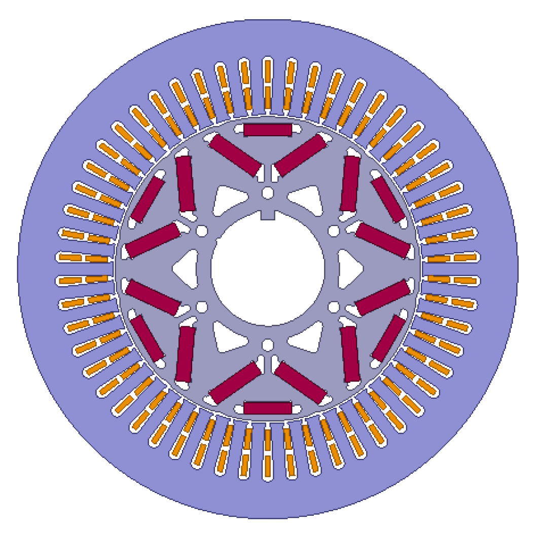
This section takes an IPMSM used as the main drive motor in a new energy vehicle as an example, as shown in Figure 1. The motor has an outer diameter of 210 mm, a stack height of 100 mm, 3 pole pairs, a rated power of 45 kW, a peak power of 140 kW, and a maximum speed of 20,000 rpm. Silicon steel materials with thicknesses of 0.30 mm, 0.20 mm, and 0.10 mm are selected to conduct a comparative study on the application differences of silicon steel with different thicknesses. In this paper, the 0.1 mm NOSS used is ESW8517, the 0.2 mm NOSS used is 20SW1200, and the 0.3 mm NOSS used is 30SW1500. The B-P and B-H data of the silicon steel sheets of each thickness specification are assigned to the stator and rotor cores of the motor model to simulate and analyze the application differences of silicon steel sheets with different thickness specifications.
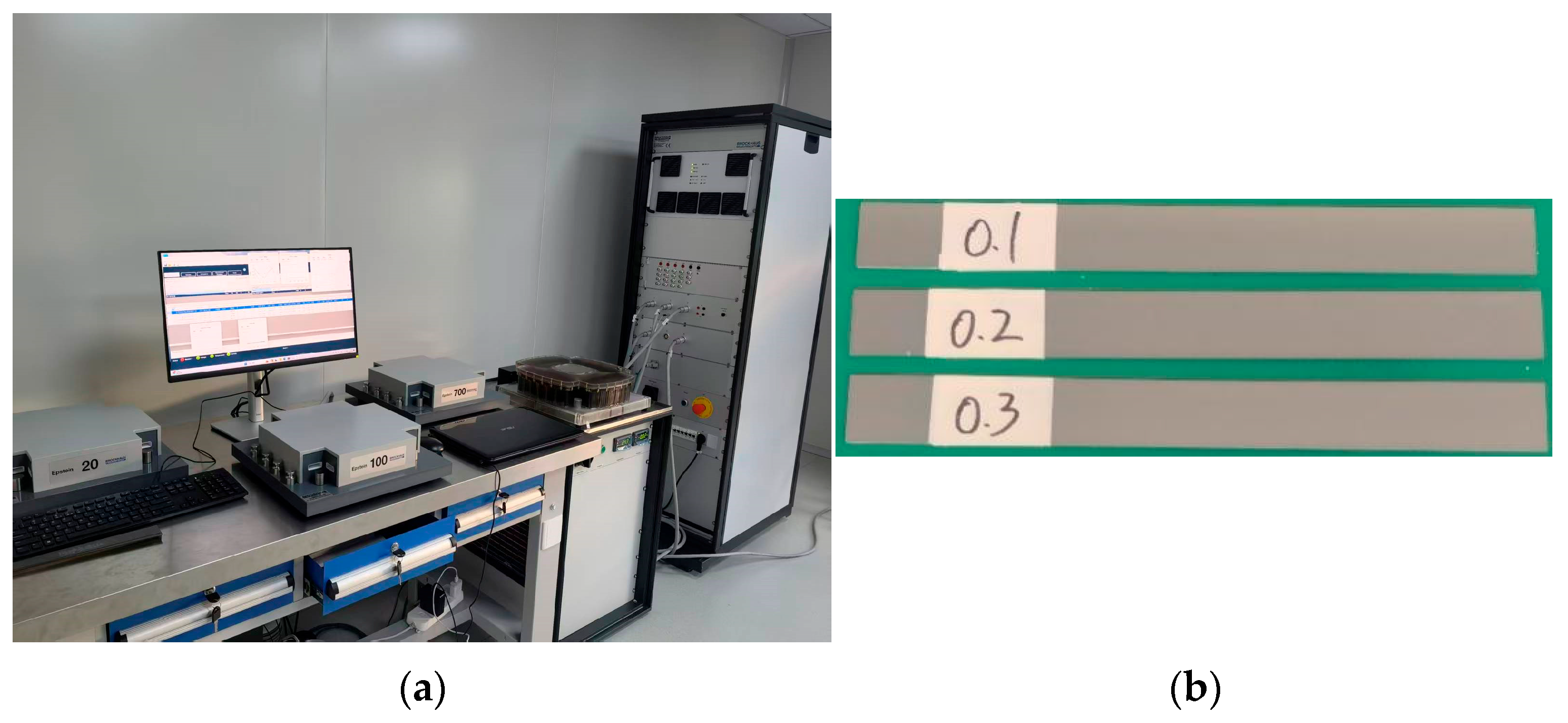
First, the magnetic properties of silicon steel materials with three typical thicknesses (0.30 mm, 0.20 mm, and 0.10 mm) were tested using the Epstein frame method and a German BROCKHAUS magnetic property measurement instrument. The test instrument and samples are shown in Figure 2. During the testing process, the test equipment is capable of monitoring the temperature of the test sample. When the temperature reaches 60 °C, the testing process is automatically terminated, thereby ensuring the reliability of the test results.
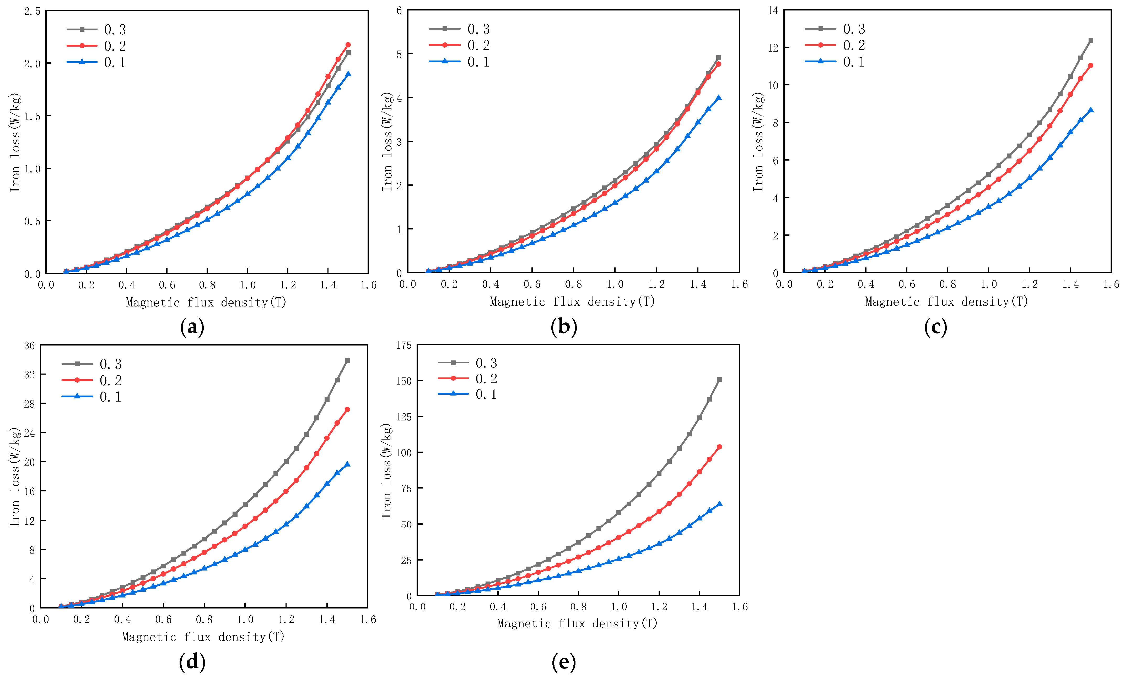
The comparison of iron loss for the tested silicon steel materials of each thickness specification under different magnetic flux densities and frequencies is shown in Figure 3. Compared to silicon steel materials with larger thicknesses, as the frequency gradually increases from 50 Hz to 2000 Hz, the loss advantage of the thinner silicon steel materials gradually increases. Due to the reduced contribution of eddy current loss at low frequencies (especially within the 100 Hz range), the benefit of thickness reduction is offset by the increase in hysteresis loss caused by residual processing stress. As a result, the loss advantage of the thinner 0.20 mm silicon steel material is not realized. Although 0.1 mm NOSS exhibits some advantage over 0.2 mm and 0.3 mm NOSS, the difference is not substantial. However, the cost increase for 0.1 mm NOSS is very high. This finding is consistent with the aforementioned theoretical analysis of silicon steel loss calculation. The loss reduction advantage of thin silicon steel materials only becomes significant when the frequency increases to the high-frequency region where eddy current loss is dominant.
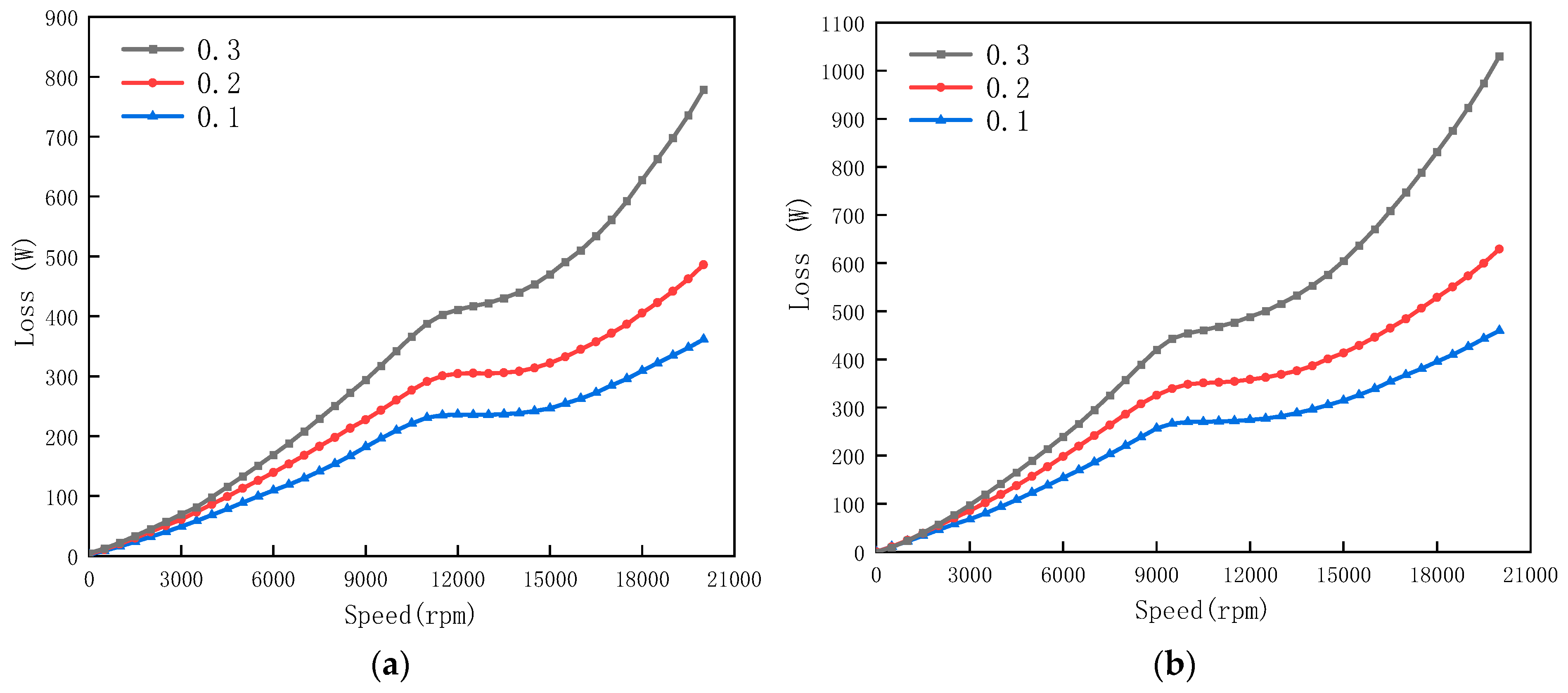
Using three types of NOSS as the stator and rotor core materials for the motor shown in Figure 1, finite element simulation software was employed to calculate the no-load and load core losses of the three motors at different rotational speeds. As shown in Figure 4, the comparison of core loss simulation results for the motor using silicon steel sheets of different thicknesses under various speeds and loads indicates that, compared to silicon steel materials with larger thicknesses, the loss advantage of thinner silicon steel materials gradually increases as the speed rises from 0 rpm to 20,000 rpm. However, at low speeds (especially within 2000 rpm, corresponding to 100 Hz), the loss advantage of the thinner 0.20 mm and 0.10 mm silicon steel materials is not realized; instead, relatively higher losses are observed (e.g., the loss of the 0.20 mm material is greater than that of the 0.30 mm material). This finding is consistent with both the aforementioned theoretical analysis of silicon steel loss calculation and the measured material loss results.
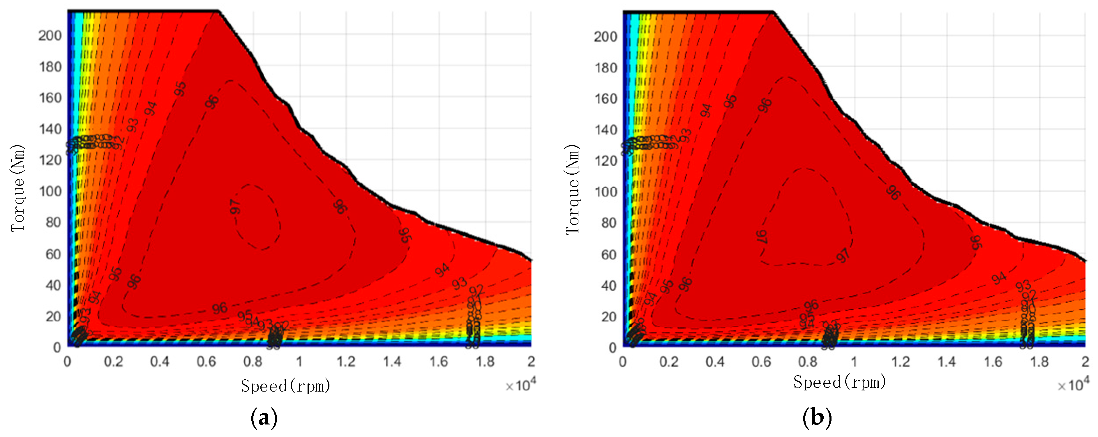
Furthermore, the comprehensive performance of the motor performance is shown in Table 1. As the thickness of the silicon steel material decreases, the maximum efficiency, average efficiency, and the proportion of the high-efficiency region of the motor all improve. In particular, the thin-gauge silicon steel material exhibits a significant advantage in the proportion of the high-efficiency region from 85% to 97%. This notable advantage in the proportion of the high-efficiency region when using 0.1 mm silicon steel material can also be intuitively observed from the motor efficiency distribution comparison in Figure 5.
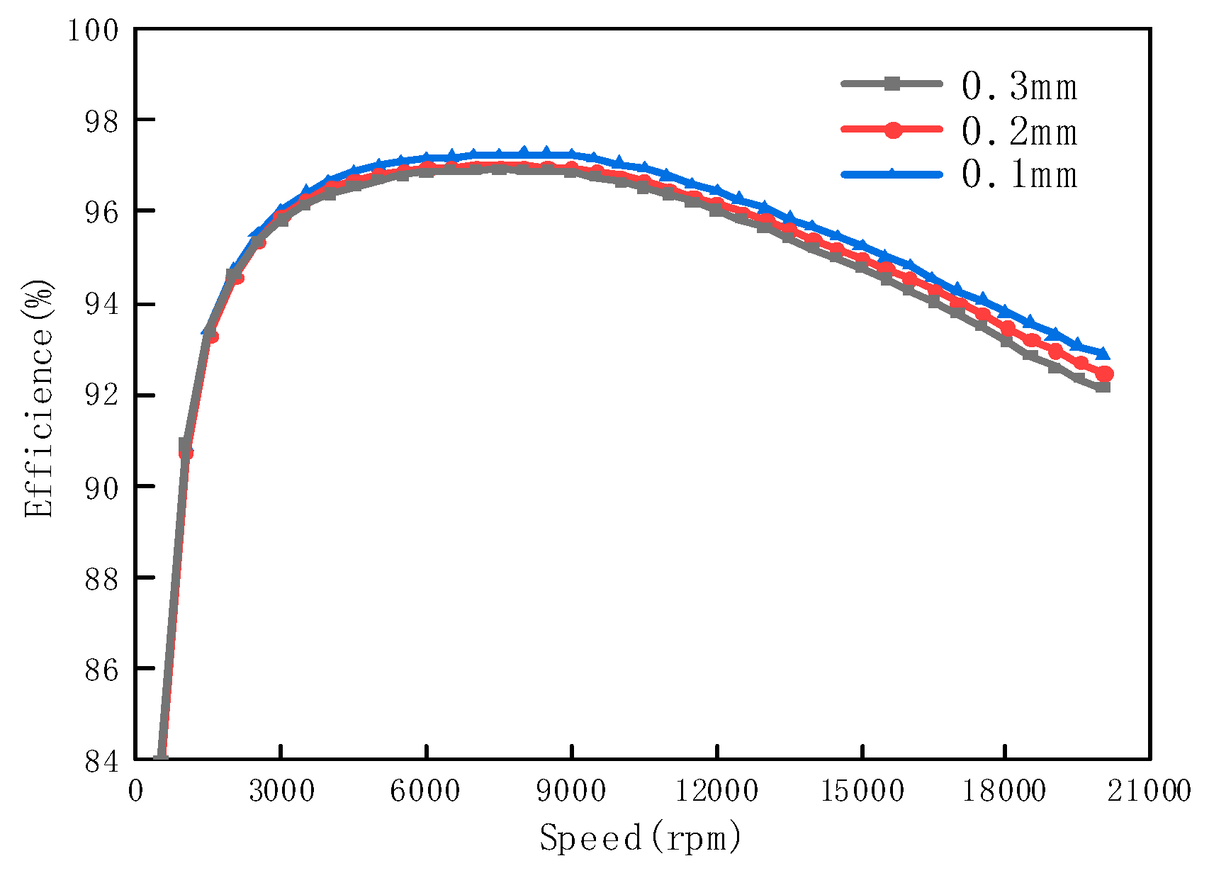
From Figure 6, which shows the efficiency comparison of motors using silicon steel materials of different thicknesses as stator and rotor core under load conditions at various speeds, it can be seen that as the speed (frequency) increases, the efficiency advantage of motors using thin-gauge silicon steel materials gradually increases. However, at low speeds (low frequencies), the efficiency advantage of motors using thin-gauge silicon steel materials is not evident. Therefore, for IPMSMs operating at low speeds and low frequencies, pursuing ever-thinner gauge silicon steel materials is not advisable. Moreover, the cost of thin-gauge silicon steel materials is relatively high. The selection should be made reasonably based on the actual operating conditions and energy efficiency requirements of the motor.

2.2. Influence Analysis of NOSS with Different Thicknesses Applied to a Rotor Core

The research results in the previous section indicate that NOSS materials with different thicknesses exhibit significant differences in iron loss (especially more pronounced at high frequencies), which directly affect the operating efficiency of the IPMSM (particularly significantly impacting the proportion of the high-efficiency region). However, since NOSS acts on both the stator core and the rotor core of the IPMSM, it remains unclear specifically whether the influence of its iron loss on the operating efficiency of the IPMSM affects the stator core or the rotor core, and to what extent. Therefore, this section focuses on investigating the specific impact of NOSS core on rotor core of the IPMSM.
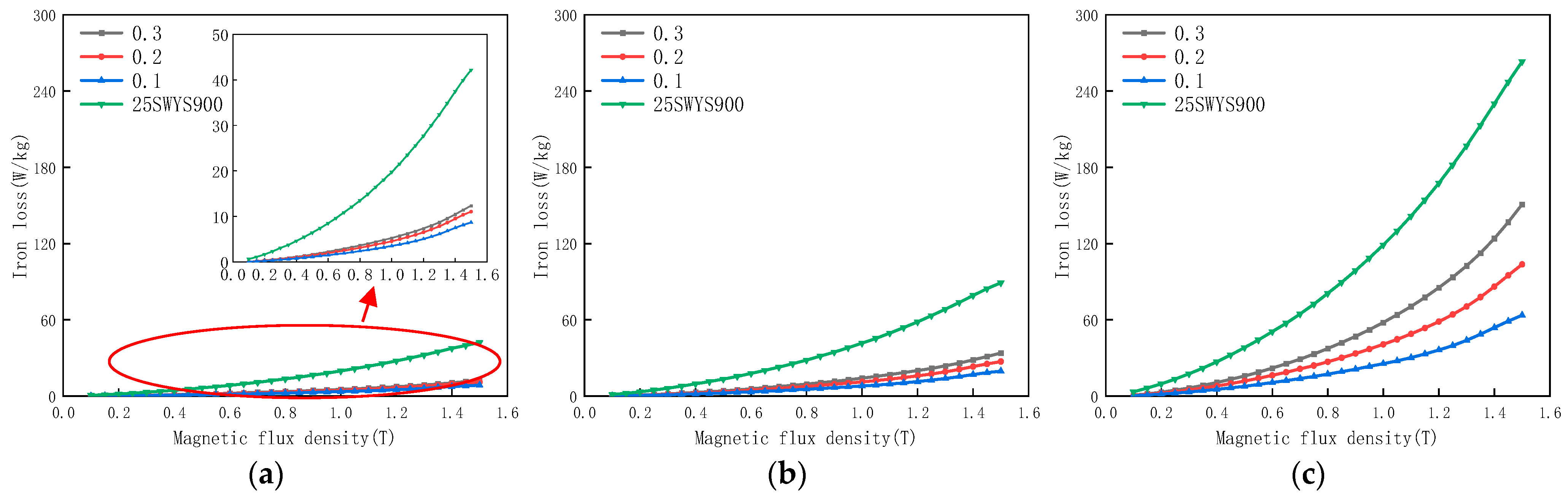
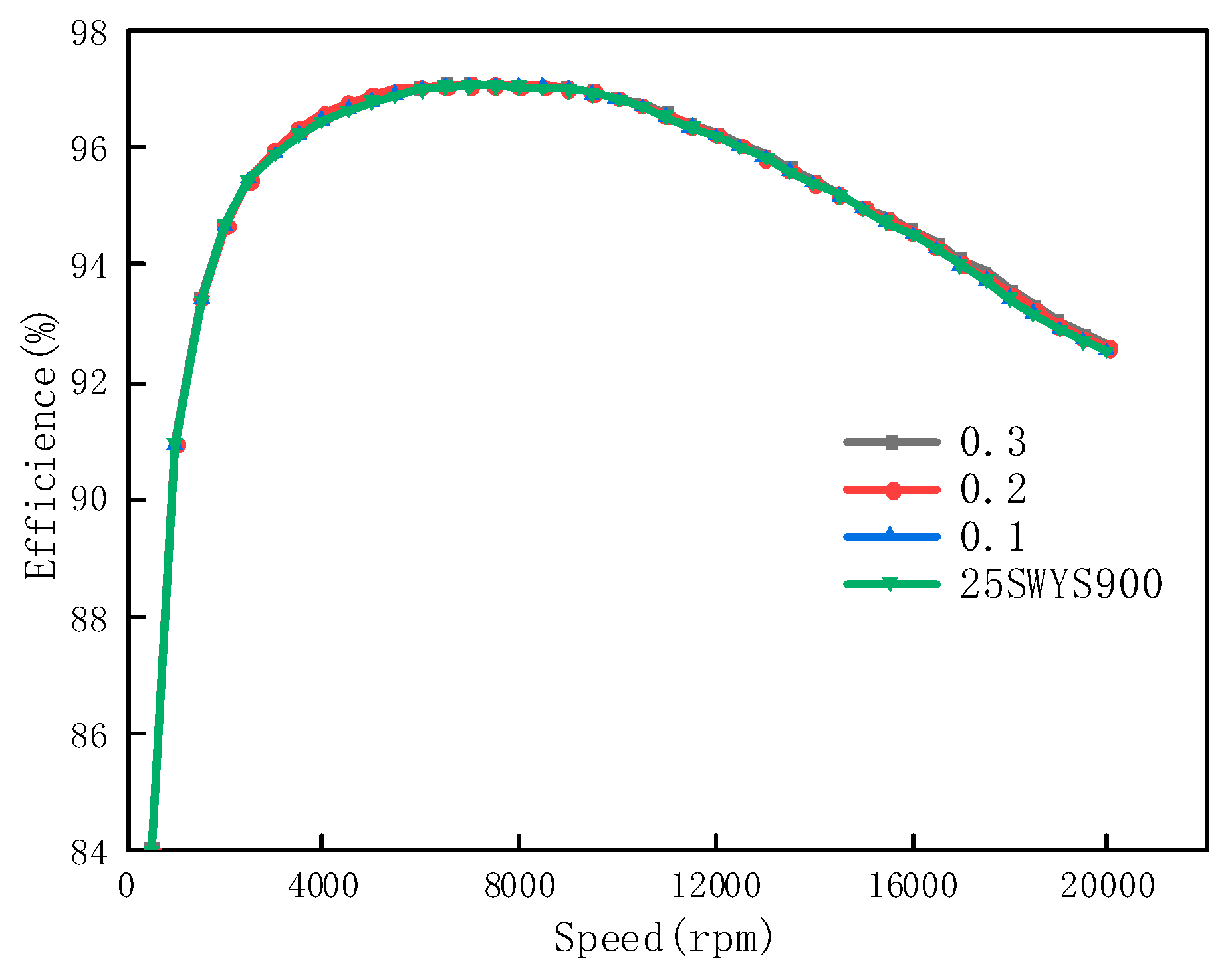
First, based on the three materials with thicknesses of 0.1, 0.2, and 0.3 mm selected in the previous section, an additional NOSS material with significantly higher loss, 25SWYS900, is included to form a set of four materials with substantial loss differences. A comparison of their losses at different frequencies is shown in Figure 7. Secondly, based on the IPMSM simulation model selected in the previous section, with all other conditions kept consistent (the magnetic flux density and iron loss of the stator core material, as well as the magnetic flux density of the rotor core material, all use data from 20SW1200), the loss data of the four materials (0.1 mm, 0.2 mm, 0.3 mm, and 25SWYS900) are sequentially assigned to the rotor core of the simulation model. The performance differences of the IPMSM are then analyzed through simulation.
The comprehensive performances of the motors with different four rotor core materials are shown in Table 2. As can be seen, the simulated IPMSM performance—including torque, efficiency, and the proportion of the high-efficiency region—remained essentially consistent across all cases. Furthermore, as shown in Figure 8, with increasing speed, the motor efficiencies simulated using the loss data schemes of the four materials did not exhibit significant differences. Therefore, it can be concluded that the operating performance of the IPMSM is not sensitive to the loss of the rotor core material. Even substantial variations in the loss of the rotor core material do not cause significant changes in the operating performance of the IPMSM.
Therefore, by integrating the findings from Section 2.1, a further conclusion can be drawn. The significant impact of NOSS with different thicknesses on the operating efficiency of the IPMSM (especially under high-speed, high-frequency conditions) is primarily exerted through the stator core. To improve operating efficiency, the stator core of the IPMSM should be made of silicon steel or other soft magnetic materials with low loss. In contrast, the material selection scheme for the rotor core of the IPMSM does not need to deliberately pursue low-loss soft magnetic materials.

3. Research on the Influence of NOSS Magnetic Flux Density on IPMSM Performance

In addition to iron loss, magnetic flux density is another important parameter for measuring the magnetic performance of NOSS materials. The B-H curve directly affects the ease of magnetization of the silicon steel material and the energy loss during the magnetization process. Therefore, the magnetic flux density index of NOSS materials may significantly impact the torque and efficiency of IPMSMs during operation.
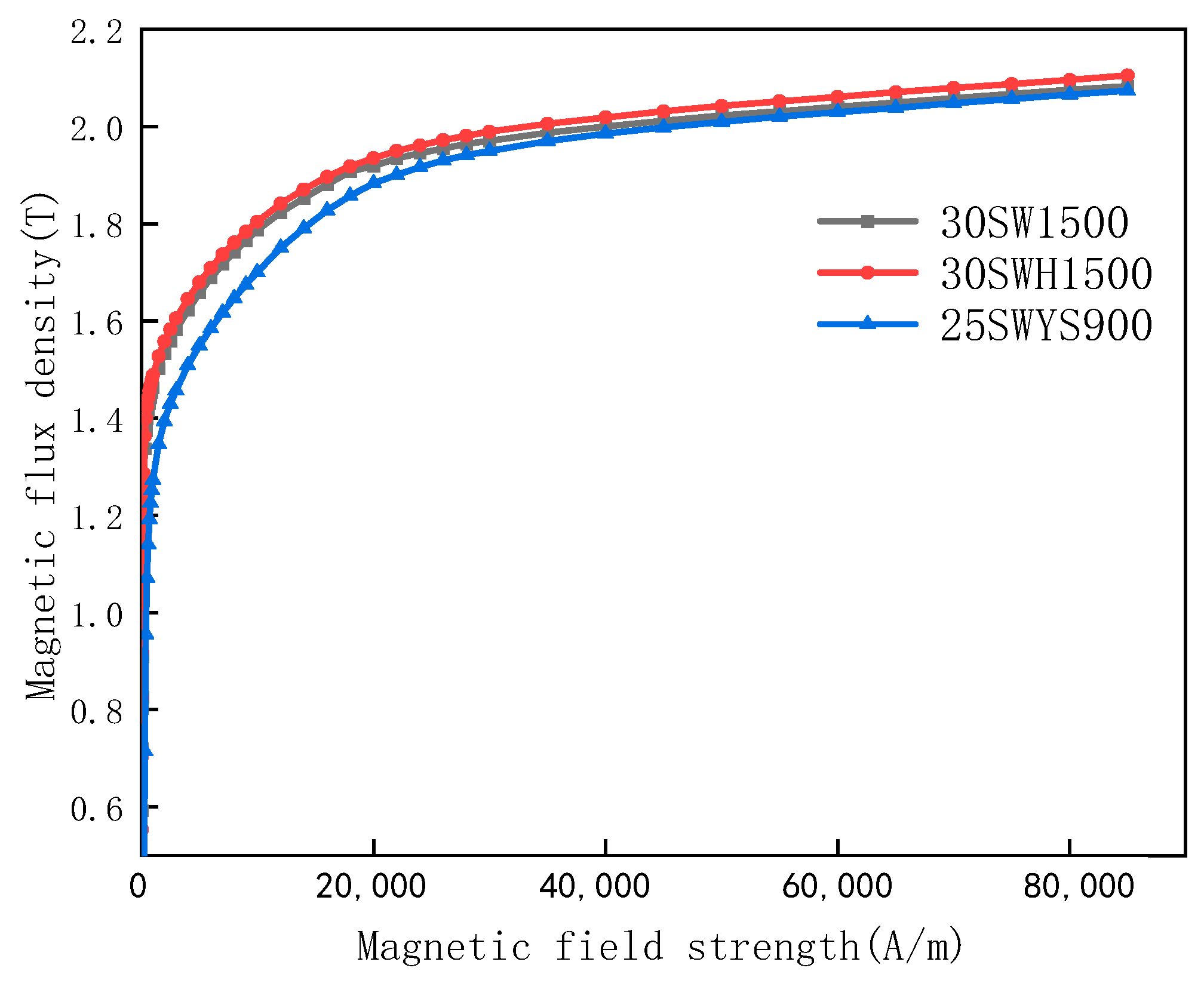
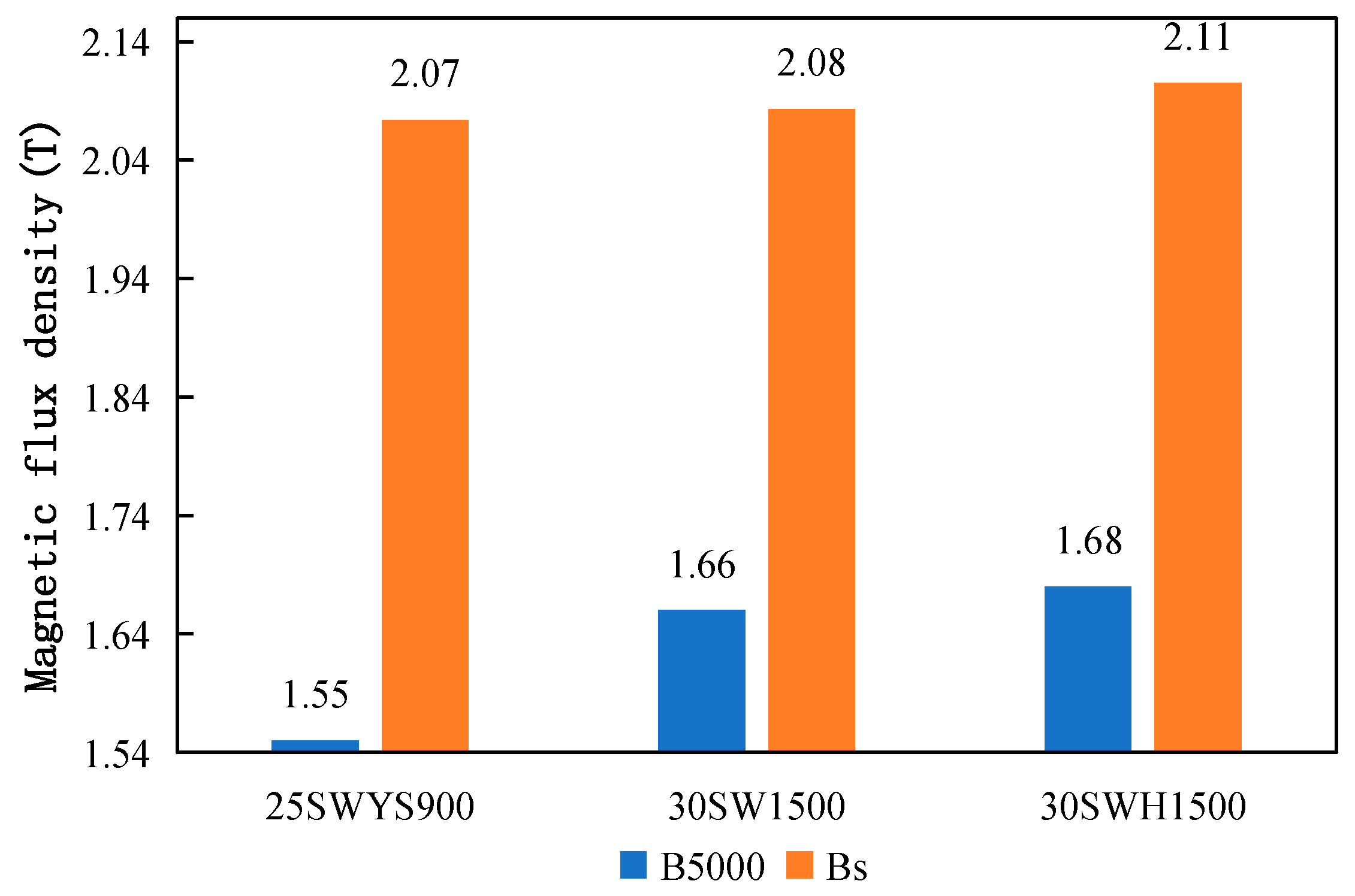
To investigate the specific influence of magnetic flux density on IPMSM, three materials with significantly different magnetization curves—30SW1500, 30SWH1500, and 25SWYS900—are selected as research subjects in this section. The test results are shown in Figure 9 and Figure 10. Compared with the B5000 (magnetic flux density at a magnetic field strength of 5000 A/m: 1.66 T) and the saturation magnetic flux density Bs (magnetic flux density at a magnetic field strength of 85,000 A/m: 2.08 T) of the 30SW1500 material, 30SWH1500 exhibits a higher magnetic flux density (especially Bs). Its B5000 and Bs are higher by 0.02 T and 0.03 T, respectively, corresponding to increases of approximately 1.2% and 1.4%. Compared with 30SW1500, 25SWYS900 exhibits a lower magnetic flux density (especially at medium-to-low magnetic field strengths ranging from 0 to 30,000 A/m). Its B5000 and Bs are lower by 0.11 T and 0.01 T, respectively, corresponding to reductions of approximately 6.6% and 0.48%. To control variables and minimize the influence of NOSS thickness on motor performance, 30SW1500 and 30SWH1500 can be used as a comparative pair. Both materials have the same thickness of 0.3 mm, while 30SWH1500 exhibits superior magnetic induction characteristics.
To eliminate the influence of the material’s iron loss index, the simulation research schemes were designed using the loss data of 30SW1500. Different magnetic flux density data were assigned to the stator core and rotor core, respectively. The simulation research schemes are shown in Table 3. The IPMSM model used in the previous sections, with an outer diameter of 210 mm, a stack height of 100 mm, 3 pole pairs, and a maximum speed of 20,000 rpm, was continued to be used. Comparison of simulation performances of different schemes are listed in Table 4.
Based on Table 3 and Table 4, to elucidate the differential impacts of B5000 and Bs on IPMSM performance, two schemes exhibiting characteristic deviations in magnetic flux density were selected for detailed comparison:
(1)
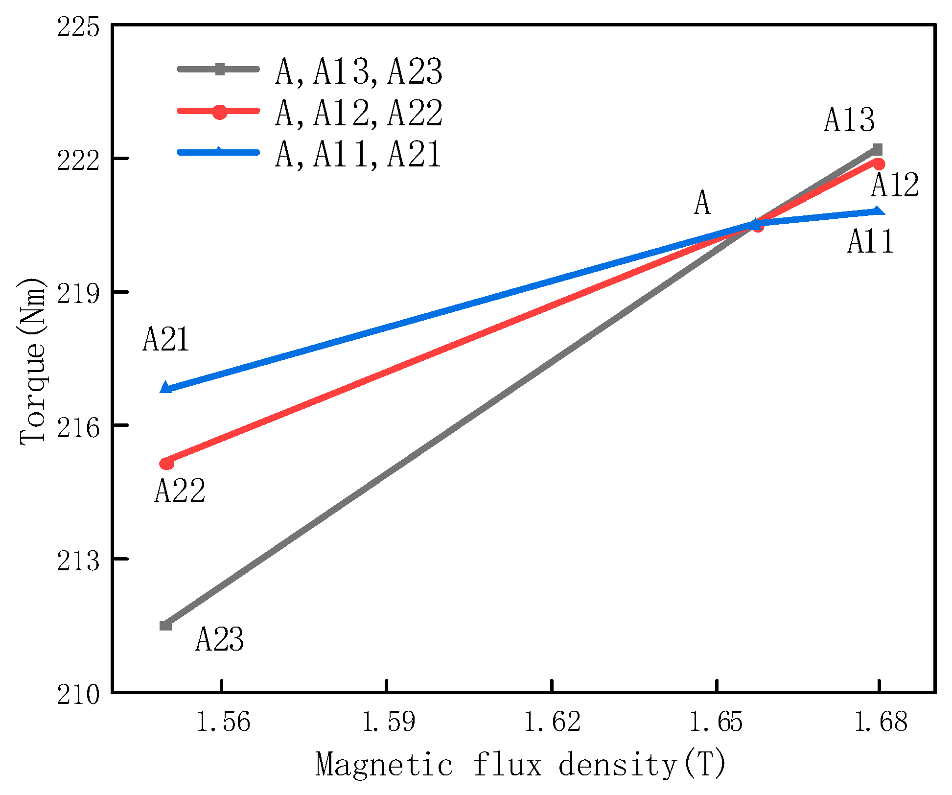
Scheme A (stator and rotor both adopting 30SW1500) and Scheme A13 (stator and rotor both adopting 30SWH1500) exhibit deviations of approximately 1% in both B5000 and Bs. Comparative results indicate that the maximum efficiency, average efficiency, and proportion of the high-efficiency region are nearly identical between the two schemes, with a torque deviation of 0.77%. This demonstrates that a 1% deviation in the B5000 and Bs of soft magnetic materials does not substantially alter IPMSM operating characteristics, indicating low motor sensitivity to minor fluctuations in magnetic flux density.
(2)
Conversely, Scheme A (stator and rotor both adopting 30SW1500) and Scheme A23 (stator and rotor both adopting 25SWYS900) present a B5000 deviation of 6.6%, whereas the Bs deviation is merely 0.48%. Simulation results reveal a pronounced torque discrepancy of 4.3% between the two schemes, which closely correlates with the B5000 deviation magnitude. This indicates that even when Bs remains essentially constant, a substantial disparity in B5000 can still induce significant fluctuations in IPMSM operating performance.
To further investigate the differential impacts of magnetic flux density on the stator and rotor cores, three comparative schemes were established, as illustrated in Figure 11: the combination schemes composed of A, A13, A23; the combination schemes composed of A, A12, A22; and the combination schemes composed of A, A11, A21. The slopes of the torque–magnetic flux density fitting curves for these three schemes decrease progressively. This trend clearly demonstrates that the magnetic flux density of the material directly affects the torque of the IPMSM through both the stator core and the rotor core. Among these, the influence exerted through the stator core on the IPMSM torque is relatively greater compared to that through the rotor core.

4. Research on the Influence of Ultra-High-Strength NOSS on IPMSM Performance

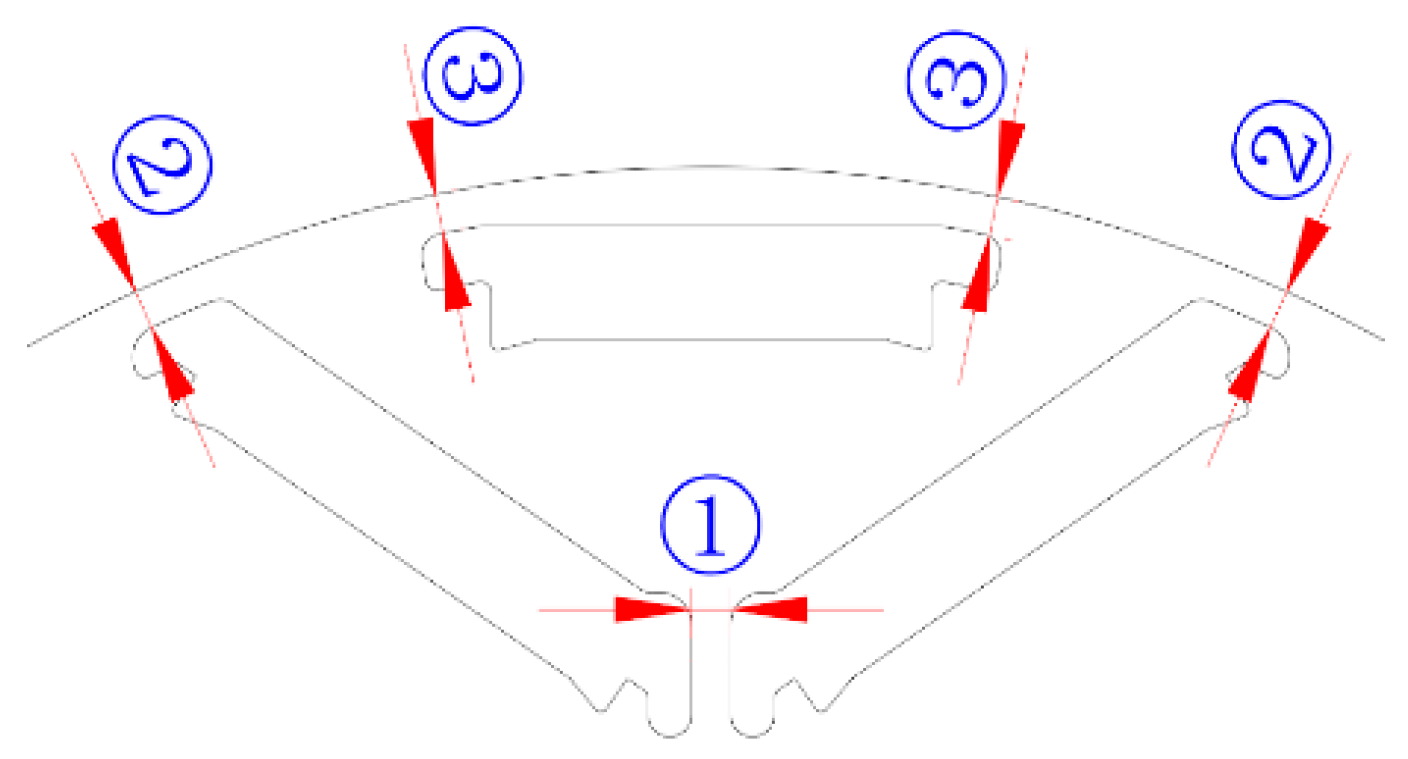
For an IPMSM, the presence of the magnetic flux barrier structure in the rotor serves two purposes. On the one hand, to reduce the leakage flux of the permanent magnets, it is necessary to minimize the width of the flux barriers, as shown in Figure 12. In the figure, ① indicates the inner flux barrier, and ② and ③ indicate the outer flux barriers. On the other hand, it functions to secure the embedded permanent magnets, preventing them from being thrown out during rotor rotation.
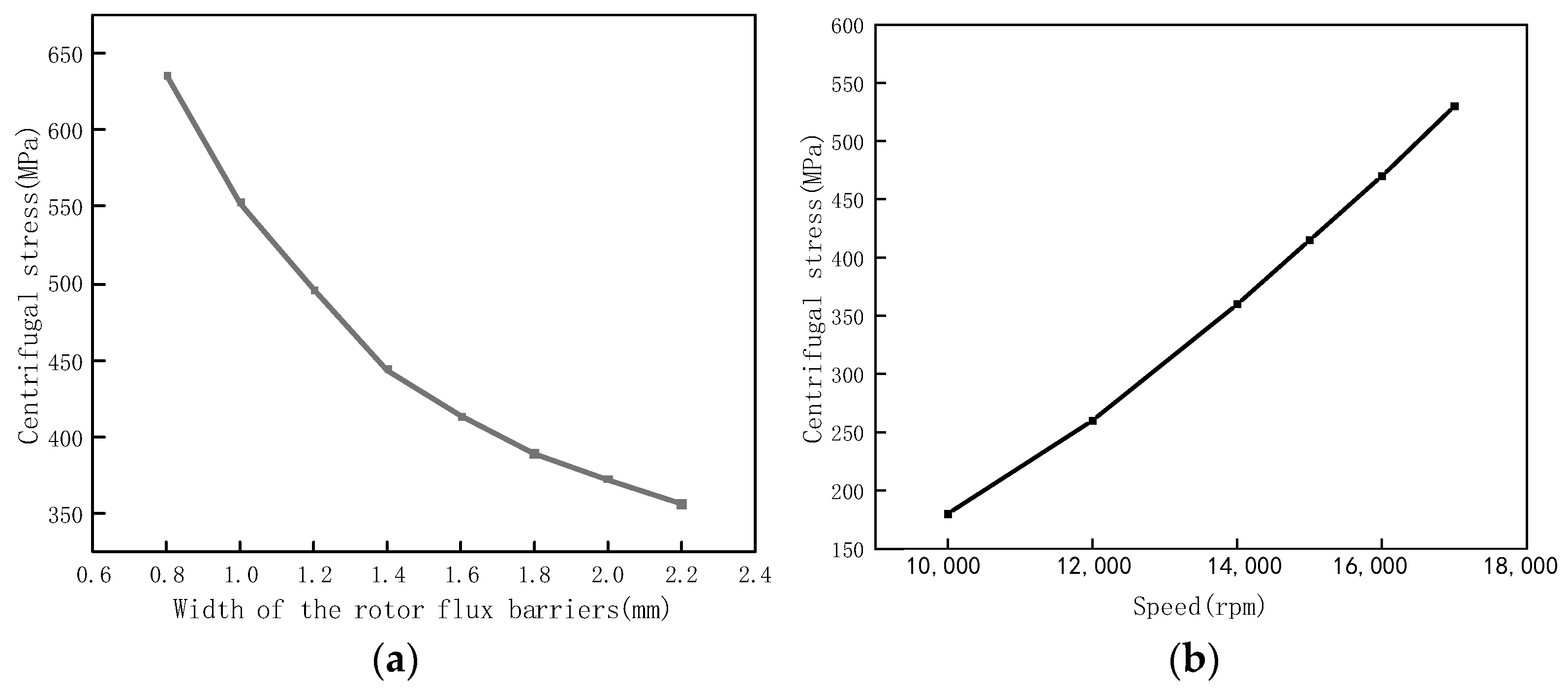
During the design process of the IPMSM rotor structure, to reduce the leakage flux at the rotor flux barriers and thereby increase the output torque of the IPMSM, it is necessary to decrease the width of the rotor flux barriers. Furthermore, to increase the output power of the IPMSM, the motor speed needs to be increased. Therefore, to enhance the power density of the IPMSM, it is necessary to both reduce the width of the rotor flux barriers and increase the speed. This inevitably results in the flux barriers being subjected to significant centrifugal stress under high-speed rotation. For a V ¯ -shaped IPMSM rotor model with a stator outer diameter of 128 mm, the variation trends of centrifugal stress on the rotor flux barriers with respect to flux barrier width and rotational speed are shown in Figure 13. This significantly increases the risk of elastic deformation of the flux barriers under high centrifugal stress, potentially leading to stator–rotor rub, or in severe cases, plastic deformation and fracture of the flux barriers. Therefore, when designing high power density IPMSMs, it is necessary to seek motor performance improvement schemes that ensure the structural safety of the rotor.
From a materials perspective, performance improvement schemes that ensure the structural safety of the IPMSM rotor mainly include wrapping the rotor with carbon fiber and applying high-strength silicon steel materials. Among these, the solution of wrapping the rotor with carbon fiber has certain application limitations, as it increases the air gap between the stator and rotor, affects rotor heat dissipation, and requires specialized carbon fiber winding equipment and techniques. Since the IPMSM rotor core itself requires the use of NOSS materials, the solution of applying NOSS materials with a high yield strength has relative advantages. The yield strength of conventional NOSS materials is only about 400 MPa, which is clearly insufficient to solve the aforementioned problem. However, the NOSS material 25SWYS900, developed by Shougang Group, has a yield strength of ≥900 MPa, making it one of the NOSS materials with the highest yield strength in the world.
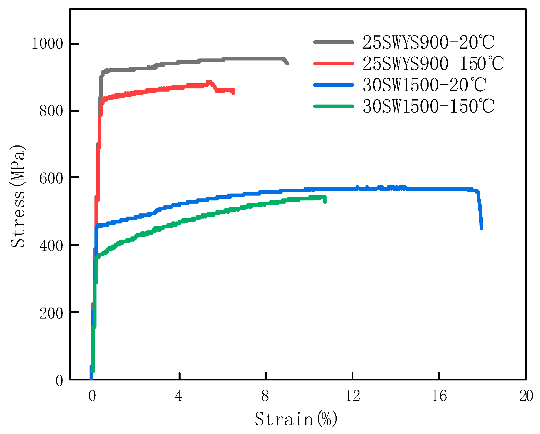
To investigate the advantages of applying ultra-high-strength NOSS materials, this section is based on a V ¯ -shaped IPMSM rotor model with a stator outer diameter of 128 mm. Two NOSS materials are selected for comparative study, as shown in Figure 14: 30SW1500 with a guaranteed yield strength of 420 MPa, and 25SWYS900 with a guaranteed yield strength of 900 MPa. A comparison of the typical stress–strain curves of the two materials at room temperature (20 °C) and high temperature (150 °C) is shown in Figure 13. Compared to room temperature (20 °C), the reduction in yield strength for both materials at high temperature (150 °C) is within 90 MPa.
To ensure the structural safety of the rotor during IPMSM design, it is necessary to fully consider the maximum centrifugal stress on the rotor flux barriers based on operating conditions such as motor speed and temperature. The maximum operating speed of the IPMSM simulation model used in this section is 20,000 rpm, and the maximum operating temperature is 150 °C. Therefore, when designing this motor model using the two materials, 30SW1500 and 25SWYS900, the maximum centrifugal stress borne by the rotor flux barriers cannot simply be limited by the guaranteed yield strength of the material at room temperature. The reduction in yield strength of the material at a high temperature of 150 °C must also be considered. Furthermore, considering possible damage to the sheared edges during the motor manufacturing process and potential overspeed conditions during actual operation, a certain safety factor should also be applied to the maximum centrifugal stress borne by the rotor flux barriers. In engineering applications, the selected safety factor is typically 1.2. Therefore, the calculation formula for the maximum allowable centrifugal stress on the rotor flux barriers when applying NOSS materials can be summarized as follows:
F = R p 0.2 90 1.2
where F is the maximum centrifugal stress borne by the rotor flux barrier; Rp0.2 is the guaranteed yield strength of the material at room temperature (20 °C); and “90” is the reduction in yield strength of the material at a high temperature of 150 °C compared to room temperature.
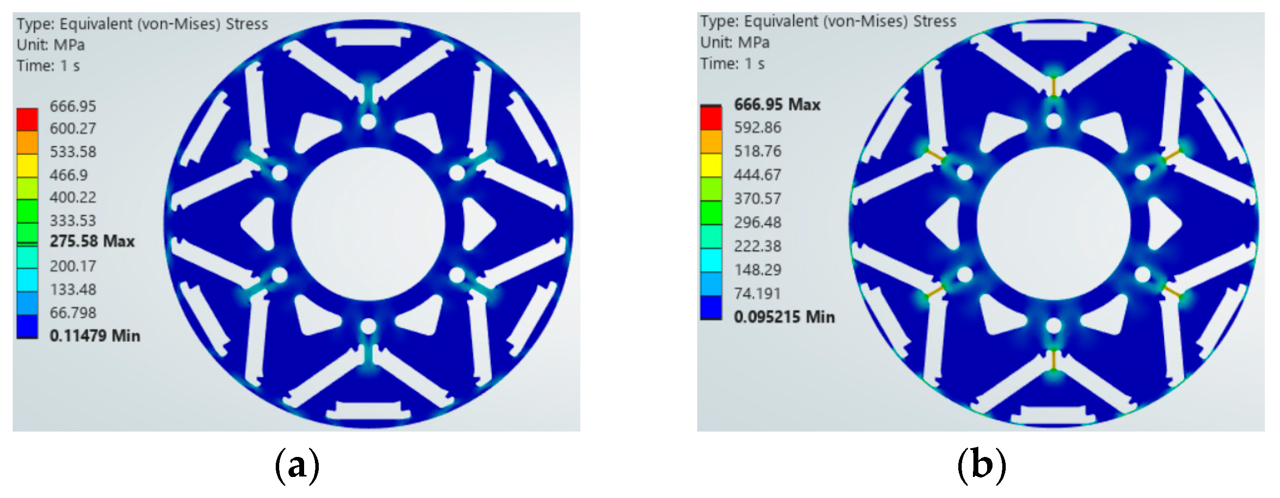
Based on Equation (5) and the guaranteed yield strengths Rp0.2 of 30SW1500 and 25SWYS900 (420 MPa and 900 MPa, respectively), theoretical calculations indicate that the maximum allowable centrifugal stresses for the rotor flux barriers are approximately 275 MPa and 675 MPa. Under this strength constraint, the flux barrier geometries were optimized for both materials. When the 35SW1500 material is used, the widths of flux barriers ①, ②, and ③ are designed as 2.4 mm, 2.0 mm, and 2.0 mm. When the 25SWYS900 material is used, the widths of flux barriers ①, ②, and ③ are designed as 1.0 mm, 0.9 mm, and 0.9 mm. The rotor centrifugal stress distribution under the two stations is shown in Figure 15. To ensure consistent visual comparison across all subfigures, the upper limit of the contour legend has been uniformly fixed at 666.95 MPa. This adjustment eliminates auto-scaling artifacts and allows direct assessment of relative stress distributions. The maximum centrifugal stresses borne by the rotor flux barriers for the motors using the 30SW1500 and 25SWYS900 materials are marked in the color spectrum, which are 275.58 MPa and 666.95 MPa, respectively. Both of them are within the safety margin requirement of the respective material.
To fully investigate the application advantages of ultra-high-strength NOSS, comparisons of the magnetic flux density and iron loss of the two materials are shown in Figure 9 and Figure 3, respectively. As mentioned in Section 3, compared with the B5000 and Bs of the 30SW1500 material, 25SWYS900 exhibits a lower magnetic flux density. Furthermore, the iron loss of the two materials also differs significantly, with a deviation exceeding 30%.
Based on the above research analysis of the performance of the two materials and the simulation-designed rotor models with different magnetic barrier parameters, the results are shown in Table 5.
Electromagnetic performance simulation analysis was conducted on the motors, and the comprehensive performance is shown in Table 6. Compared with Scheme 1, in which both the stator and rotor use 30SW1500, Scheme 2—which adopts the same rotor flux barrier design but uses 25SWYS900 for the rotor—exhibits essentially the same power and efficiency, with only a 1.7% reduction in torque. In contrast, Scheme 3, which uses 25SWYS900 and features an optimized rotor flux barrier design, demonstrates significant advantages in torque, power, and the proportion of the 97% high-efficiency region, with a 9.2% increase in maximum torque, a 9.1% increase in maximum power, and higher proportion of the 97% high-efficiency region. When 25SWYS900 is applied to both the stator and the rotor (Scheme 4), although torque and power show notable improvements (increases of 4.8% and 9.1%, respectively), significant disadvantages appear in maximum efficiency, average efficiency, and the proportion of the high-efficiency region. Therefore, the ultra-high-strength material 25SWYS900 is not suitable for the stator of IPMSMs and should only be used for the rotor.
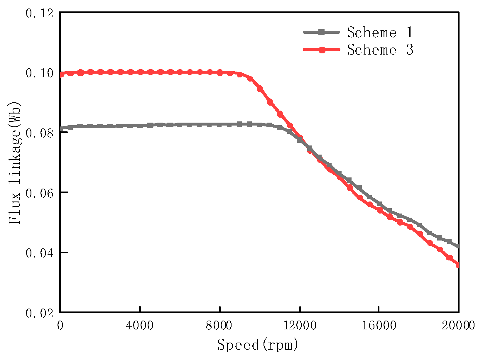
Furthermore, by combining the comparison of D-axis flux linkage at different speeds between Scheme 1 and Scheme 3, as shown in Figure 16, it can be further explained that applying the 25SWYS900 material to reduce the width of the rotor flux barrier can effectively reduce leakage flux, thereby increasing the effective magnetic flux. At the same time, this also mitigates the disadvantages of the ultra-high-strength 25SWYS900 material in terms of magnetic flux density and iron loss, ultimately resulting in an enhancement of the overall performance of the IPMSM.

5. Experimental Verification

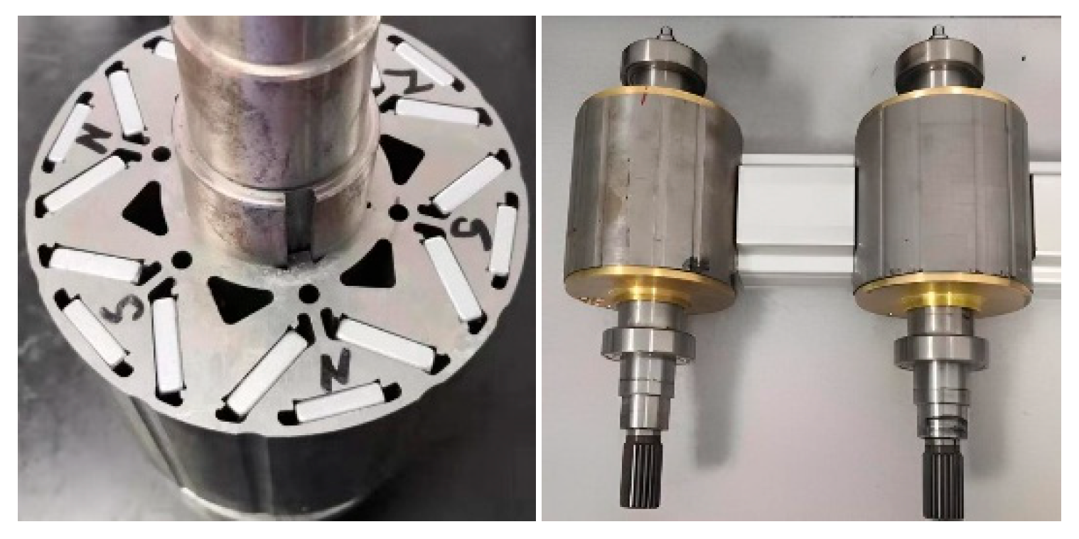
Based on the IPMSM model studied in the previous section, prototypes were manufactured using 30SW1500 and 25SWYS900, with the schemes shown in Table 7. To conserve experimental resources and rapidly obtain experimental results showing deformation or even fracture of the rotor flux barriers, the outer flux barrier widths of two of the prototypes were machined to 0.5 mm. The rotor structure and rotor images of the prototypes are shown in Figure 17.
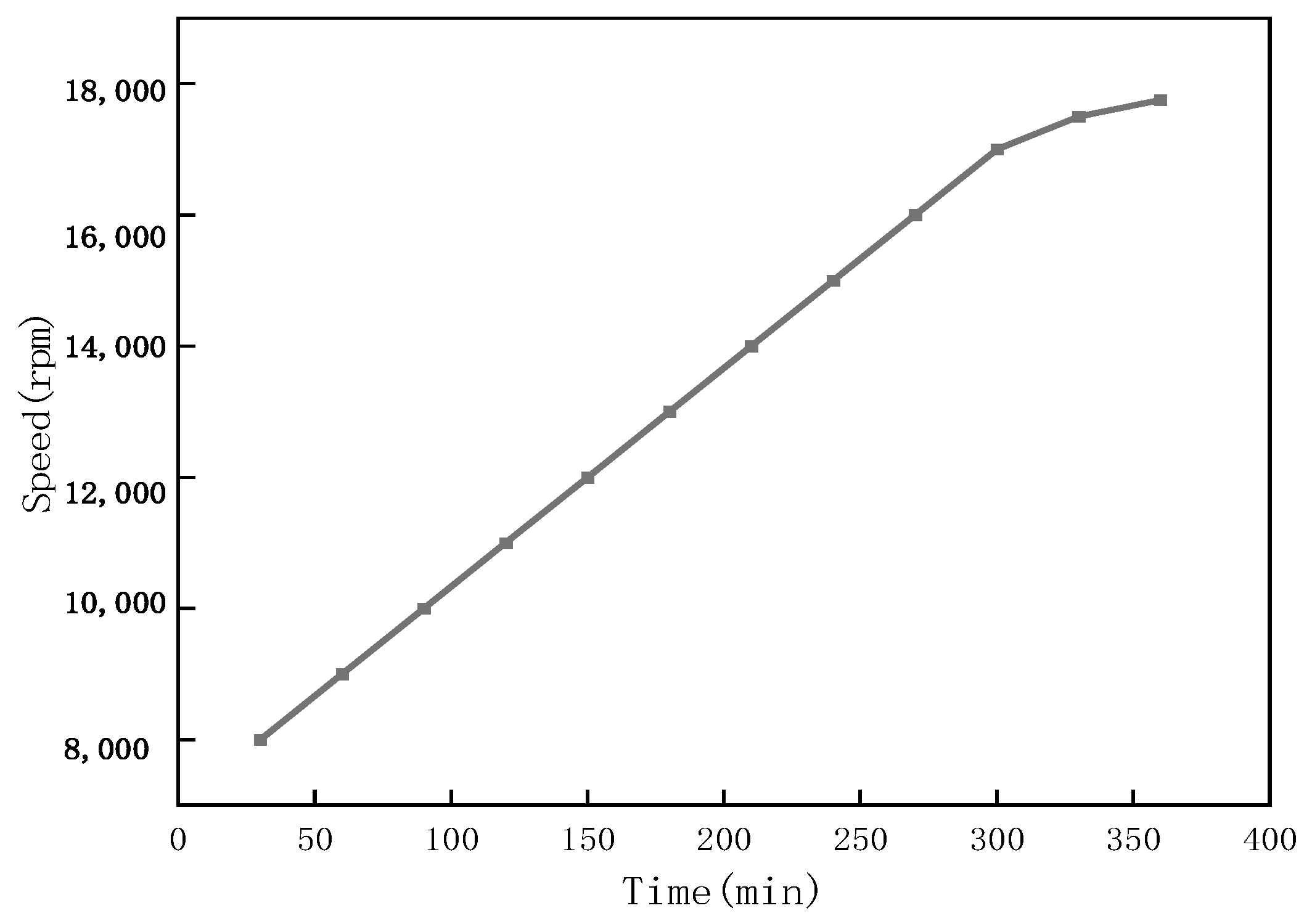
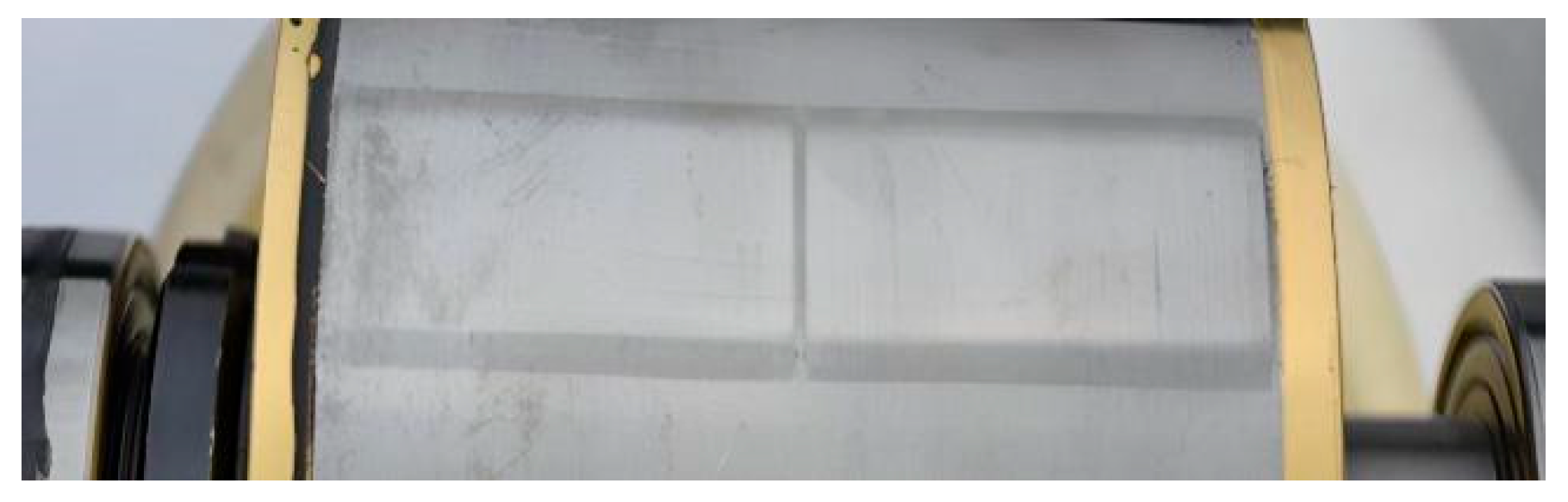
To verify the plastic deformation of the rotor material under centrifugal stress, testing was conducted on a new energy motor test bench for the Scheme 4 and Scheme 3 prototypes. The test results are shown in Figure 18. The motor speed started at 8000 rpm and was gradually increased to 17,000 rpm in steps of 1000 rpm/30 min. No deformation was observed in the rotors of the Scheme 4 and Scheme 3 prototypes. Considering that the rotor material of the Scheme 4 prototype was approaching its critical speed, the experiment continued with steps of 250 rpm/30 min. When the test speed reached 17,750 rpm, the rotor of the Scheme 3 prototype exhibited obvious plastic deformation, as shown in Figure 19, while no visible change was observed in the rotor of the Scheme 3 prototype. During the experiment, the rotor outer diameter was measured before and after each speed change, and the dimensional changes were recorded. The dimensions of the rotor in the Scheme 3 prototype showed no change. The outer diameter measurement results for the rotor of the Scheme 4 prototype are shown in Table 8. Measurements were taken at both ends of the rotor, with three measurements taken at each end, and the average of the three measurements was calculated. The deformation rates for the rotor of the Scheme 4 prototype were 0.82% and 0.81%, respectively. It is evident from the deformation photographs that the rotor core material of the Scheme 4 prototype reached its yield strength at 17,750 rpm. However, since fracture had not yet occurred, the material’s tensile strength was not exceeded.
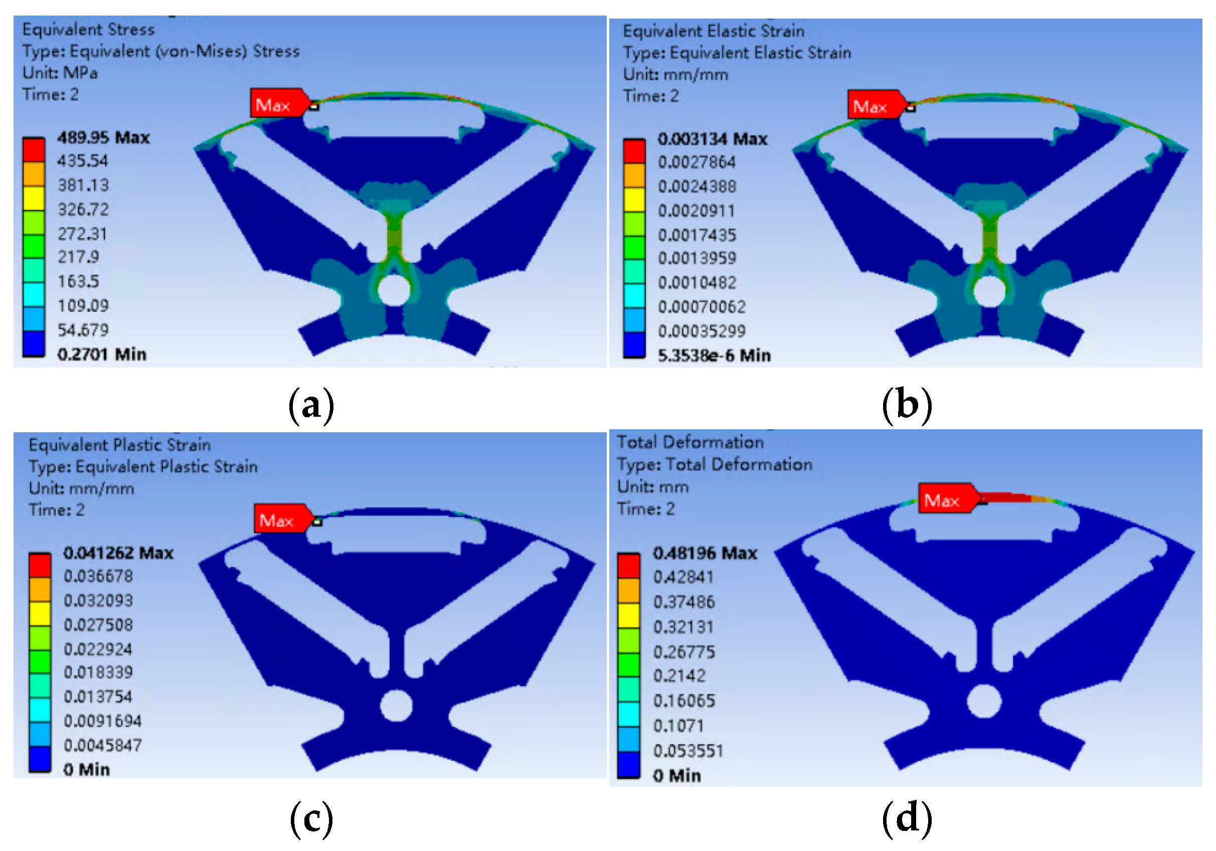
The simulation results for the stress and strain of the rotor of the Scheme 4 prototype during high-speed rotation at 17,750 rpm are shown in Figure 20. The maximum centrifugal stress, 489.95 MPa, occurs at the outer flux barrier ③. The rotor deformation is dominated by plastic strain, generally following the rule that the displacement increases with distance from the axis. The maximum bilateral deformation of the rotor is 0.96 mm, which is essentially consistent with the measured deformation result of 1.03 mm, with a deviation of only 7.3%.
To make a comparison with the simulation performance presented earlier and to validate the accuracy of the simulation analysis, four prototypes were manufactured in this study. The design schemes of the prototypes are shown in Table 9. Tests were conducted at a typical speed of 7500 rpm for medium-speed operating conditions in new energy vehicles, with a current of 230 A applied during the tests. As shown in Table 9, the performance of the prototype using the ultra-high-strength material 25SWYS900 is essentially equivalent to that of the prototype using the conventional material 30SW1500, which is consistent with the previous simulation results. When the width of the outer flux barrier was reduced from 2.0 mm to 0.5 mm, the motor torque increased from 154.69 Nm to 165.21 Nm, representing an increase of 6.8%, which is consistent with the simulation trend. The above comparisons strongly demonstrate the reliability of the conclusions drawn from the previous simulation analysis.


6. Conclusions

The loss, magnetic flux density, mechanical properties, and other characteristics of different core materials significantly influence IPMSM performance. By studying the effects of different core materials on IPMSMs, an optimal material combination can be identified to enhance the overall motor performance. This paper investigates the performance impact of different silicon steel materials on a V ¯ -shaped IPMSM. The main research logic and conclusions are as follows:
(1)
The influence pattern of silicon steel material iron loss performance on IPMSMs: As the thickness of the silicon steel material decreases, the motor’s maximum efficiency, average efficiency, and the proportion of the high-efficiency region can all be improved. At low speeds, the performance advantage of motors using thin-gauge silicon steel materials is not significant; as speed increases, the efficiency advantage of motors using thin-gauge silicon steel materials gradually becomes more pronounced. The influence of silicon steel material iron loss performance on IPMSM performance is primarily exerted through the stator core; therefore, the stator core should be made of silicon steel materials with low loss.
(2)
The influence pattern of silicon steel material magnetic flux density performance on IPMSMs: The operating performance of the IPMSM is not very sensitive to the magnetic flux density of the silicon steel material. However, when there are significant differences in magnetic flux density under medium-to-low magnetic field strengths (between 0 and 30,000 A/m), it can also cause notable changes in the operating efficiency, torque, and power of the IPMSM. The magnetic flux density performance of both the stator core and the rotor core affects the torque of the IPMSM, with the influence of the stator being relatively greater.
(3)
The influence pattern of silicon steel material mechanical properties on IPMSMs: Applying ultra-high-strength NOSS allows for a reduction in the width of the rotor magnetic flux barrier, thereby effectively increasing the effective magnetic flux. Ultimately, this yields beneficial effects such as significantly improving the operating performance of the IPMSM in terms of torque, power, and the proportion of the high-efficiency region. However, the iron loss and magnetic flux density of ultra-high-strength NOSS are relatively poor; therefore, it is only suitable for manufacturing the rotor of the IPMSM.
(4)
Finally, a prototype of a PMSM motor is manufactured and tested, and the experimental results validate the finite element method (FEM) simulations.

Author Contributions

Conceptualization, G.L. and J.Z.; methodology, G.L.; software, G.L. and X.G.; validation, G.L., J.Z. and X.G.; investigation, G.L. and Z.C.; resources, B.W.; data curation, Z.C. and X.G.; writing—original draft preparation, G.L.; writing—review and editing, X.G.; visualization, X.G. All authors have read and agreed to the published version of the manuscript.

Funding

This research received no external funding.

Data Availability Statement

The datasets presented in this article are not readily available due to technical and time limitations. Requests to access the datasets should be directed to liguanglin@sgqg.com.

Acknowledgments

In order to improve English writing and reduce English grammar errors, part of the manuscript content is polished by DeepSeek V3.2. The authors have reviewed and edited the output and take full responsibility for the content of this publication.

Conflicts of Interest

Authors Guanglin Li and Bin Wang were employed by the company Shougang Zhixin Electromagnetic Material (Qian’an) Co., Ltd. All the authors declare that the research was conducted in the absence of any commercial or financial relationships that could be construed as a potential conflict of interest.

References

  1. Hwang, S.-W.; Son, D.-K.; Park, S.-H.; Lee, G.-H.; Yoon, Y.-D.; Lim, M.-S. Design and Analysis of Dual Stator PMSM with Separately Controlled Dual Three-Phase Winding for eVTOL Propulsion. IEEE Trans. Trans. Elec. 2022, 8, 4255–4264. [Google Scholar] [CrossRef]
  2. Chen, H.; Tang, J.; Liu, Y.; Jiang, B.; Boscaglia, L. Electromagnetic Performance Investigation of a Brushless Electrically Excited Synchronous Machine for Long-Distance Heavy-Duty Electric Vehicles. IEEE Trans. Trans. Elec. 2024, 11, 225–235. [Google Scholar] [CrossRef]
  3. Choo, K.-M.; Won, C.-Y. Design and Analysis of Electrical Braking Torque Limit Trajectory for Regenerative Braking in Electric Vehicles with PMSM Drive Systems. IEEE Trans. Power Elec. 2020, 35, 13308–13321. [Google Scholar] [CrossRef]
  4. Shen, J.; Wang, X.; Zhang, Z.; Ren, S.; Ma, D.; Xiao, D. Research on the Application of Dual Three-Phase PMSM in Renewable Energy System. In Proceedings of the 2023 26th International Conference on Electrical Machines and Systems (ICEMS), Zhuhai, China, 5–8 November 2023; pp. 3475–3479. [Google Scholar]
  5. Siadatan, A.; Kalantarikhalilabad, A.; Rezaei-Zare, A. Reliability and Fault-Tolerance Assessment of PMSM Drive for Electric Aircraft Applications. In Proceedings of the 2023 IEEE International Electric Machines & Drives Conference (IEMDC), San Francisco, CA, USA, 15–18 May 2023; pp. 1–7. [Google Scholar]
  6. Thangavel, S.; Mohanraj, D.; Girijaprasanna, T.; Raju, S.; Dhanamjayulu, C.; Muyeen, S.M. A Comprehensive Review on Electric Vehicle: Battery Management System, Charging Station, Traction Motors. IEEE Access 2023, 11, 20994–21019. [Google Scholar] [CrossRef]
  7. Wang, Z.; Ching, T.W.; Huang, S.; Wang, H.; Xu, T. Challenges Faced by Electric Vehicle Motors and Their Solutions. IEEE Access 2020, 9, 5228–5249. [Google Scholar] [CrossRef]
  8. Murali, N.; Ushakumari, S.; Mini, V.P. Performance comparison between different rotor configurations of PMSM for EV application. In Proceedings of the 2020 IEEE Region 10 Conference (TENCON), Osaka, Japan, 16–19 November 2020; pp. 1334–1339. [Google Scholar]
  9. Hayashi, S.; Kubota, Y.; Soma, S.; Ohtani, M.; Igarashi, H. Topology Optimization of Permanent Magnet Synchronous Motor Considering the Control System. IEEE Trans. Magn. 2022, 58, 8205605. [Google Scholar] [CrossRef]
  10. Sasaki, H.; Yamamura, K. Topology Optimization with Shapley Additive Explanations for Permanent Magnet Synchronous Motors. IEEE Trans. Magn. 2023, 60, 8201304. [Google Scholar] [CrossRef]
  11. Cvetkovski, G.; Petkovska, L. Performance Improvement of PM Synchronous Motor by Using Soft Magnetic Composite Material. IEEE Trans. Magn. 2008, 44, 3812–3815. [Google Scholar] [CrossRef]
  12. Ma, D.; Li, J.; Tian, B.; Zhang, H.; Li, M.; Pei, R. Studies on Loss of a Motor Stator Iron Core with High Silicon Electrical Steel Considering Temperature and Compressive Stress Factors. In Proceedings of the 2022 IEEE 5th International Electrical and Energy Conference (CIEEC), Nangjing, China, 27–29 May 2022; pp. 4243–4248. [Google Scholar]
  13. Yogal, N.; Lehrmann, C.; Shen, B.; Henke, M. Loss comparison of non-oriented electrical steel materials to be used in PMSM under explosion protection aspects. In Proceedings of the 2015 17th European Conference on Power Electronics and Applications (EPE’15 ECCE-Europe), Geneva, Switzerland, 8–10 September 2015; pp. 1–7. [Google Scholar]
  14. Fang, S.; Liu, H.; Wang, H.; Yang, H.; Lin, H. High Power Density PMSM with Lightweight Structure and High-Performance Soft Magnetic Alloy Core. IEEE Trans. Appl. Super. 2019, 29, 0602805. [Google Scholar] [CrossRef]
  15. Zhou, P.; Xu, Y.; Zhou, G. Research on High Power Density Design Method of PMSM Based on the Highly Saturated Motor Core. IEEE Trans. Ind. Electron. 2025, 72, 14061–14072. [Google Scholar] [CrossRef]
  16. Li, W.; Li, Y.; Xie, Z.; Liu, Z.; Li, Z.; Li, Y.; Zeng, L.; Pei, R. Analysis of Magnetic Properties of Self-bonding Electrical Steel and Its Application in High-speed PMSMs. IEEE Trans. Ind. Appl. 2026, 1–11. [Google Scholar] [CrossRef]
  17. Ahn, J.-H.; Choi, J.-Y.; Park, C.H.; Han, C.; Kim, C.-W.; Yoon, T.-G. Correlation Between Rotor Vibration and Mechanical Stress in Ultra-High-Speed Permanent Magnet Synchronous Motors. IEEE Trans. Magn. 2017, 53, 8209906. [Google Scholar] [CrossRef]
  18. Wang, Z.; Wang, T.; Xu, Z.; Zhang, F.; Zhang, H. Strength and Dynamics Analysis of the Novel Composite Rotor in a High-Speed Permanent Magnet Motor. IEEE Trans. Trans. Elec. 2024, 11, 6742–6752. [Google Scholar] [CrossRef]
  19. Zeng, L.; Zhang, N.; Xie, Z.; Lu, X.; Liu, X.; Pei, R. Material Selection Analysis of Amorphous Alloys and Silicon Steel for Permanent Magnet Synchronous Motors at Different Speeds. In Proceedings of the 2025 19th Conference on Electrical Machines, Drives and Power Systems (ELMA), Sofia, Bulgaria, 19–21 June 2025; pp. 1–5. [Google Scholar]
  20. O’Donnell, D.; Bartos, S.; Tjong, J.; Kar, N.C. Utilization of Innovative Materials toward Permanent Magnet Synchronous E-Motors for Traction Application: A Review. In Proceedings of the 2020 2nd International Conference on Smart Power & Internet Energy Systems (SPIES), Bangkok, Thailand, 15–18 September 2020; pp. 380–385. [Google Scholar]
Figure 1. Simulation model topology diagram.
Machines 14 00538 g001
Figure 2. Instrument and samples: (a) BROCKHAUS magnetic property measurement instrument; (b) Epstein frame method test samples.
Machines 14 00538 g002
Figure 3. Comparison of iron loss of NOSS with different thicknesses at different frequencies: (a) 50 Hz; (b) 100 Hz; (c) 200 Hz; (d) 400 Hz; (e) 1000 Hz.
Machines 14 00538 g003
Figure 4. Comparison of iron core loss of motors with NOSS of different thicknesses under various speeds and loads: (a) no-load; (b) load.
Machines 14 00538 g004
Figure 5. Comparison of efficiency distribution: (a) motor with 0.3 mm silicon steel sheet; (b) motor with 0.1 mm silicon steel sheet.
Machines 14 00538 g005
Figure 6. Comparison of motor efficiency under load conditions using silicon steel sheets of different thicknesses at various speeds.
Machines 14 00538 g006
Figure 7. Comparison of iron loss of different silicon steel materials at various frequencies: (a) 200 Hz; (b) 400 Hz; (c) 1000 Hz.
Machines 14 00538 g007
Figure 8. Comparison of efficiency under different rotor core materials.
Machines 14 00538 g008
Figure 9. Comparison of test results for the magnetic flux density curves of the materials.
Machines 14 00538 g009
Figure 10. Comparison of typical magnetic flux density B5000 and Bs of materials.
Machines 14 00538 g010
Figure 11. Comparison of different simulation combination schemes (horizontal axis: typical magnetic flux density B5000 of the material).
Machines 14 00538 g011
Figure 12. Schematic diagram of the magnetic flux barrier structure.
Machines 14 00538 g012
Figure 13. Variation of centrifugal stress on the magnetic flux barrier: (a) different flux barrier widths; (b) different rotational speeds.
Machines 14 00538 g013
Figure 14. Comparison of the mechanical properties of the two materials.
Machines 14 00538 g014
Figure 15. Centrifugal stress distribution of the rotor magnetic flux barrier: (a) 30SW1500; (b) 25SWYS900.
Machines 14 00538 g015
Figure 16. Comparison of D-axis flux linkage between Scheme 1 and Scheme 3 at different speeds.
Machines 14 00538 g016
Figure 17. Rotor core of the prototype.
Machines 14 00538 g017
Figure 18. Schematic diagram of the rotor high-speed test process.
Machines 14 00538 g018
Figure 19. Rotor high-speed test deformation.
Machines 14 00538 g019
Figure 20. Rotor deformation calculation results: (a) equivalent stress (MPa); (b) elastic strain (mm/mm); (c) plastic strain (mm/mm); (d) unilateral deformation (mm).
Machines 14 00538 g020
Table 1. Performance comparison of three types of NOSS when applied to the stator and rotor of the motor.
Material Thickness/mm0.30.20.1
Max Eff/%97.197.397.4
Ave Eff/%89.589.789.9
Proportion of high efficiency region/%85%87.988.394.7
90%79.980.686.8
95%49.151.656.9
96%29.632.437.7
97%2.16.211.2
Table 2. Comparison of motor performance when four types of NOSS are applied to the motor rotor.
Material Thickness/mm0.30.20.125SWYS900
Max T/Nm216.23216.17216.17216.21
Ave T/Nm87.4987.4487.4487.45
Max Eff/%97.2497.2697.2697.23
Ave Eff/%89.789.7289.7189.68
Proportion of high efficiency region/%85%88.1688.3388.1688.08
90%80.680.680.680.44
95%51.7251.6451.4751.05
96%33334132431.91
97%6.386.216.86.13
Table 3. Motor design schemes with different material combinations.
SchemeMagnetic Induction Intensity Assignment Scheme
StatorRotor
A30SW150030SW1500
A1130SW150030SWH1500
A1230SWH150030SW1500
A1330SWH150030SWH1500
A2130SW150025SWYS900
A2225SWYS90030SW1500
A2325SWYS90025SWYS900
Table 4. Comparison of motor performance using different NOSS material combinations.
AA11A12A13A21A22A23
Max T/Nm220.5220.8221.9222.2216.8215.2211.5
Max P/Kw155155.5155.5155.5155155155.8
Max Eff/%97.1297.1197.1297.1497.1197.0897.06
Ave Eff/%89.4689.4389.4789.4889.589.4189.47
Proportion of high efficiency region/%85%87.8587.6987.7987.887.9187.6686.31
90%79.8779.6279.979.8379.8579.4378.3
95%49.0848.9248.9249.0548.8747.7747.16
96%29.6228.7928.929.0528.8827.5427.46
97%2.082.162.332.742.12.271.34
Table 5. Design schemes for ultra-high-strength motors with different materials and different topologies.
NumStator MaterialRotor
MaterialFlux Barrier (①, ② and ③)
130SW150030SW1500(2.4 mm, 2.0 mm and 2.0 mm)
230SW150025SWYS900(2.4 mm, 2.0 mm and 2.0 mm)
330SW150025SWYS900(1.0 mm, 0.9 mm and 0.9 mm)
425SWYS90025SWYS900(1.0 mm, 0.9 mm and 0.9 mm)
Table 6. Comparison of motor performance using ultra-high-strength NOSS under different design schemes.
1234
Max T/Nm220.5216.8240.7231.4
Max P/Kw155155169.1169.1
Max Eff/%97.1297.197.2396.43
Ave Eff/%89.4689.589.5888.63
Proportion of high efficiency region/%85%87.8587.8488.2586.03
90%79.8779.7880.0976.26
95%4 9.0848.8349.9335.42
96%29.6228.6130.6910.23
97%2.082.276.210
Table 7. Prototype manufacturing scheme.
SchemeWidth of ①/mmWidth of ② and ③/mmStatorRotor
12.42.030SW150030SW1500
22.42.030SW150025SWYS900
32.40.530SW150025SWYS900
42.40.530SW150030SW1500
Table 8. Outer diameter measurement results of the rotor before and after deformation.
SchemeFront/mmBack/mm
BeforeAfterBeforeAfter
1125126.01124.96126
2125.02126.08124.94125.94
4125.02126.03124.94125.97
Ave125.01126.04124.95125.97
Rate of change0.82%0.81%
Table 9. Test results of different prototypes at 7500 rpm and 230 A.
SchemePerformance
Width of Flux Barrier ② and ③/mmStator MaterialRotor MaterialT/NmEff/%
2.030SW150030SW1500154.8494.60
2.030SW150025SWYS900154.6994.59
0.530SW150025SWYS900165.2194.89
0.530SW150030SW1500Used for destructive experiments; performance not tested
Disclaimer/Publisher’s Note: The statements, opinions and data contained in all publications are solely those of the individual author(s) and contributor(s) and not of MDPI and/or the editor(s). MDPI and/or the editor(s) disclaim responsibility for any injury to people or property resulting from any ideas, methods, instructions or products referred to in the content.