1. Introduction
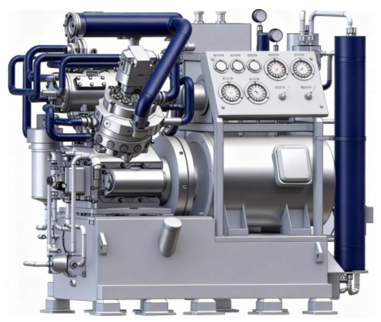
As a key component in ship propulsion and auxiliary systems, a V-type high-pressure air compressor, as shown in
Figure 1, has a direct impact on the operational reliability and acoustic performance of marine power plants. Its vibration and noise characteristics are closely associated with ship stealth capability, service life of onboard equipment, and crew comfort. During operation, the reciprocating motion of the crank-connecting rod mechanism generates periodic inertial forces, which act as the primary source of mechanical excitation responsible for structural vibration and noise radiation [
1]. However, existing inertial force balancing approaches are mainly developed under simplified assumptions, where higher-order inertial effects and structural flexibility are often neglected. As a result, the vibration mitigation performance achieved in practical engineering applications may deviate significantly from design predictions [
2].
In recent years, advances in computational mechanics and numerical simulation techniques have significantly promoted research on the balancing and optimization of reciprocating machinery. Xie et al. [
3] proposed a closed-form approach for inertial force evaluation based solely on Fourier transformation, which effectively improves the computational accuracy of inertial forces in crank-connecting rod mechanisms. Bai et al. [
4] performed multibody dynamic simulations and balance mass optimization for a dual-row crank-connecting rod system using ADAMS(2024.2), and comparatively evaluated the performance of complete and partial balancing strategies. Meanwhile, rigid–flexible coupled dynamic analyses that account for clearance effects [
5], friction [
6,
7], and component flexibility [
8] have become essential for enhancing the predictive capability of numerical simulations. For marine applications, effective noise and vibration control requires an integrated optimization framework spanning from inertial excitation sources to structural vibration and acoustic radiation [
9].
Recent studies on reciprocating compressors and crank-driven machinery have increasingly emphasized that dynamic behavior is governed not only by classical inertial force excitation, but also by time-varying inertia characteristics [
10], structural flexibility, clearance-induced nonlinearity, tribological effects, and valve motion [
11,
12]. In particular, the torsional response of compressor shaft systems has been shown to be highly sensitive to the variable inertia of crank-connecting rod mechanisms, while rigid–flexible coupling analyses further reveal that fit clearance and collision clearance may significantly modify vibration amplitude, transmission characteristics, and resonance-related behavior [
11,
13,
14]. At the same time, friction and wear influence contact conditions and energy dissipation, thereby affecting both reliability and vibration performance under real operating conditions [
15]. In compressors with coupled transmission chains, gear-related dynamic effects should also be carefully considered because time-varying mesh stiffness and shafting coupling can substantially alter torsional vibration propagation [
16]. Moreover, valve dynamics has been demonstrated to be an important secondary excitation source due to its strong interaction with pressure pulsation and transient flow evolution [
17,
18]. Nevertheless, for marine V-type high-pressure air compressors, systematic studies on the coupled effects of structural flexibility of key components, gear-induced additional dynamics, and support excitation transmission remain limited. As a result, inertial force balancing based solely on a purely rigid-body model may lead to underestimation or misjudgment of the actual excitation transfer behavior, especially in higher-order response components.
In this study, a marine V-type dual-row high-pressure air compressor with a cylinder bank angle of γ = 60° is investigated. Although conventional inertial force balancing methods are useful for preliminary design, they are generally established under rigid-body assumptions and may not accurately reflect the actual dynamic behavior of high-speed compressors when the flexibility of key components is considered. Therefore, the scientific problem addressed in this work is how to improve the accuracy of inertial force balancing analysis and balance mass design for a marine V-type compressor under more realistic structural conditions. To solve this problem, a unified research framework combining theoretical inertial force analysis, counter-rotating gear balancing design, ANSYS-based flexible-body modeling, ADAMS multibody dynamics, and DOE–surrogate–GRG optimization is established. The novelty of this work lies in integrating rigid–flexible coupled dynamics into the balancing design and quantitatively revealing the influence of crankshaft and connecting rod flexibility on support reaction force prediction and balance optimization.
2. Basic Theory of Inertial Forces
2.1. Calculation of Unbalanced Inertial Forces
The inertial force system of a marine V-type high-pressure air compressor mainly consists of rotating inertial forces as well as first-order and second-order reciprocating inertial forces. Based on kinematic analysis, the piston displacement
, velocity
, and acceleration
can be expressed as functions of the crank rotation angle
[
19]:
where
is the crank radius,
is the connecting rod ratio,
is the connecting rod length, and
is the angular velocity of the crankshaft. For a V-type compressor, if the first bank is taken as the reference bank, and the crank angle of the first bank at a certain instant is, then the crank angle of the second bank at the same instant is. Accordingly, the functional relationship between the crank angles of the first and second banks at the same instant can be expressed as in Equation (2).
The components of the reciprocating inertial force acting on the
cylinder in the
and
directions can be expressed as follows [
6]:
First-order reciprocating inertial force:
Second-order reciprocating inertial force:
Rotating inertial force:
where
denotes the reciprocating mass of the
cylinder,
represents the sum of the unbalanced rotating mass of the crankshaft and the rotating mass of the big end of the connecting rod, and
is the phase angle of the cylinder.
The expressions for piston displacement, velocity, and acceleration used in this paper are derived from the classical kinematic relations of the crank-connecting rod mechanism, while the decomposition of rotating inertial force, first-order reciprocating inertial force, and second-order reciprocating inertial force follows standard dynamic formulations for reciprocating machinery. On this basis, the resultant relation of the first-order inertial force is further adapted for the V-type dual-row configuration and its included-angle characteristic is investigated in this study.
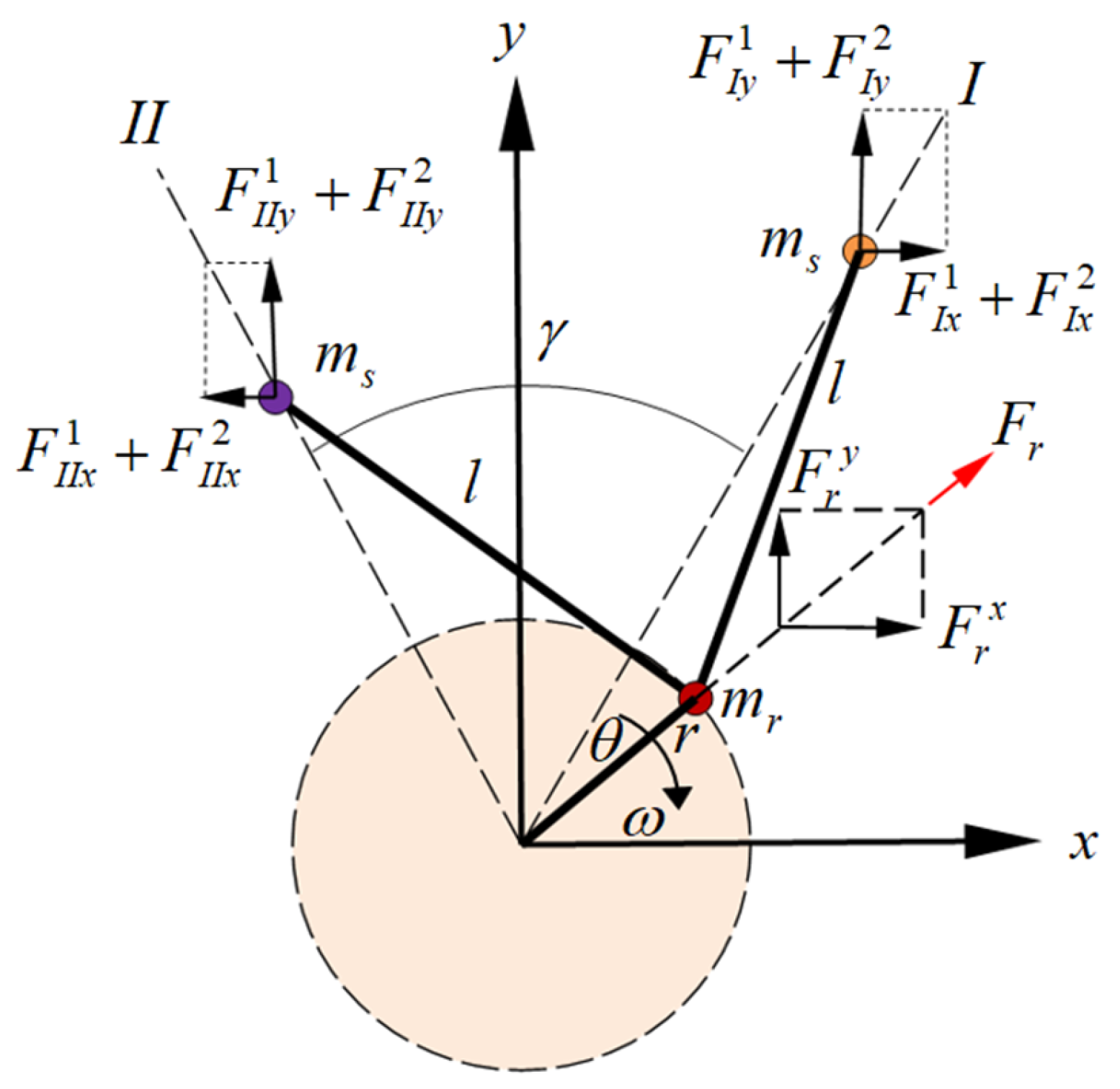
For the V-type dual-row high-pressure air compressor investigated in this study, the structural configuration is shown in
Figure 2. Assuming that the reciprocating masses of the two cylinder banks are both equal to
, and the phase difference between the two banks is
. The expressions of the first-order and second-order reciprocating inertial forces and the rotating inertial force in the
and
directions can be written as follows:
First-order reciprocating inertial force:
Second-order reciprocating inertial force:
As indicated by Equations (1)–(3), the resultant first-order reciprocating inertial force forms an elliptical locus with the major axis three times the minor axis. The resultant second-order reciprocating inertial force corresponds to a circular locus with a radius of , while the rotating inertial force also traces a circular locus with a radius of .
2.2. Inertial Force Balancing with a Counter-Rotating Gear System
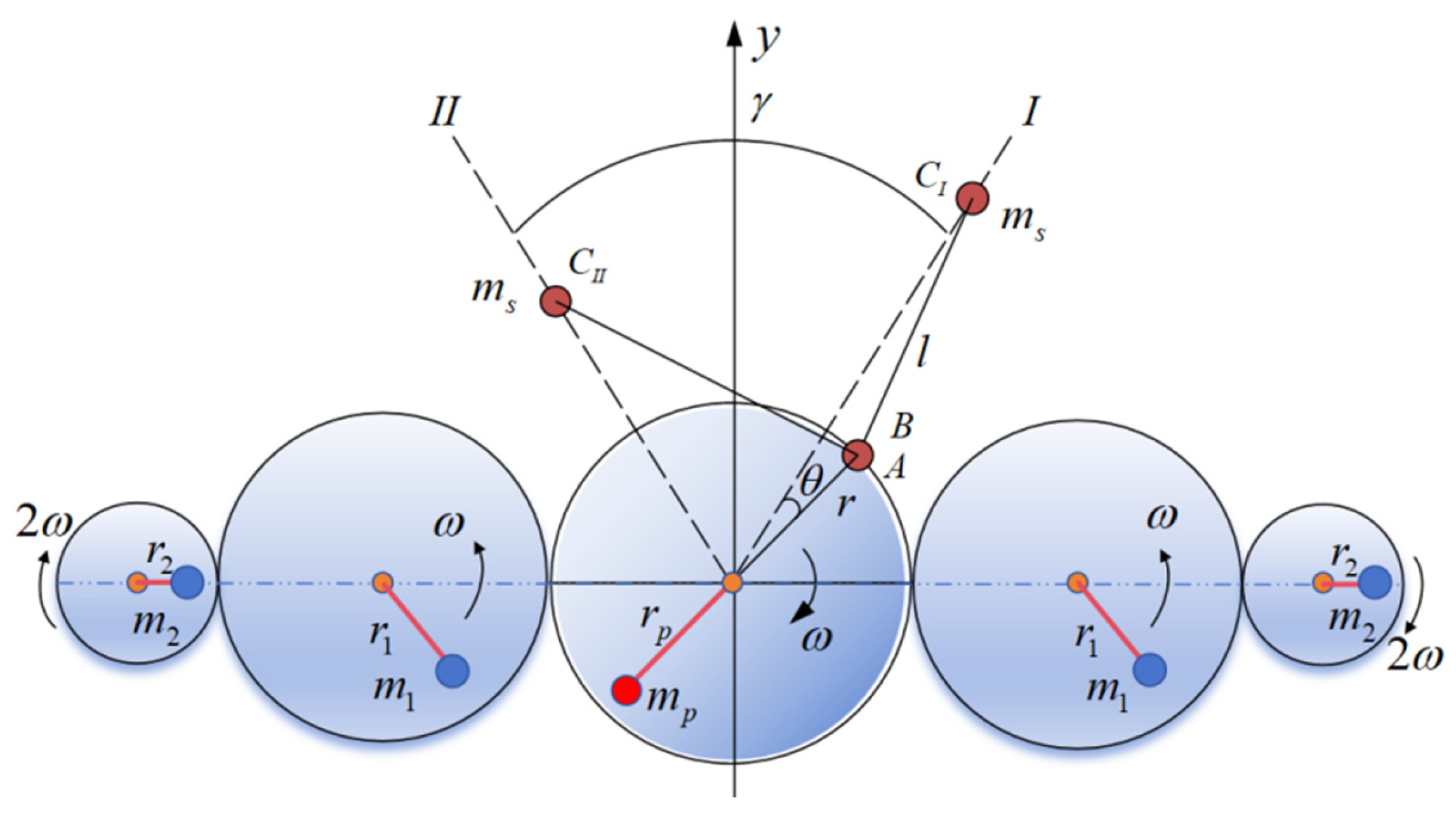
To counteract the aforementioned inertial forces, the marine high-pressure air compressor is equipped with a counter-rotating gear system with balance mass, as illustrated in
Figure 3. The balancing strategy of the counter-rotating gear system is based on the use of crankshaft balance weights to fully compensate the rotating inertial forces and partially offset the first-order reciprocating inertial forces [
2,
20]. The objective is to ensure that the resultant of the remaining first-order inertial forces after initial balancing approximates a circular locus. Subsequently, first-order balance weights are employed to further balance the residual first-order inertial forces, while second-order balance weights are introduced to independently compensate the second-order reciprocating inertial forces. The corresponding theoretical formulations are presented as follows:
2.2.1. Balancing of Rotating Inertial Forces
For the balancing of rotating inertial forces, balance mass
es are added along the extension of the crankshaft, such that the mass centers of the moving components are equivalently transferred to the crankpin center, the center of the big end of the connecting rod, and the piston pin center using the static replacement method. By introducing appropriate balance mass
es on the crankshaft extension, the following conditions are required to be satisfied:
where
and
represent the unbalanced mass and the associated radius used to completely balance the rotating inertial forces and to partially compensate the first-order inertial forces, respectively.
2.2.2. Balancing of Reciprocating Inertial Forces
For reciprocating inertial forces, both the first-order and second-order components vary with . Therefore, the positions and masses of the balance weights should be properly designed such that the resulting inertial forces minimize the resultant force as much as possible.
The residual first-order reciprocating inertial force is compensated by a first-order balance weight, which is required to satisfy the following conditions:
Residual first-order inertial force is determined by the following equations:
The mass of the first-order balance weight is determined by the following equations:
For the second-order reciprocating inertial force, its phase is twice that of the crankshaft rotational phase. Accordingly, the rotational speed of the second-order balance weight is twice the crankshaft speed, and the corresponding balance mass is required to satisfy the following equations:
2.3. Rigid-Body Modeling and Simulation
The investigated drive system consists of the crankshaft, two connecting rod–piston branches, first-order balance weights, second-order balance weights, and a counter-rotating gear train. The crankshaft converts rotary motion into reciprocating motion of the two piston rows through the crank-connecting rod mechanism, while the counterrotating gear system drives the first- and second-order balance weights to generate compensating inertial forces for reducing the first and second-order excitation components. The main compressor parameters are listed in
Table 1.
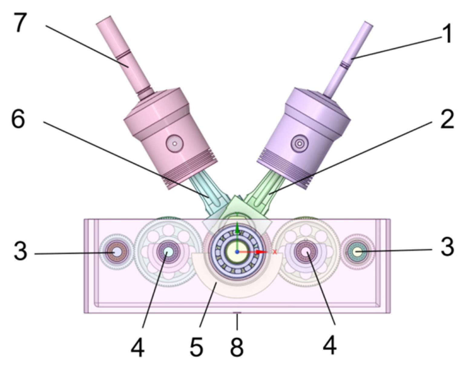
To evaluate the balancing performance of the counter-rotating gear system, a three-dimensional model of the crankshaft-connecting rod–piston assembly of the marine high-pressure air compressor is established, as shown in
Figure 4. Pure rigid-body dynamic simulations are conducted using ADAMS, and the reaction forces at the support force monitoring locations are extracted to assess the effectiveness of the balancing strategy.
2.3.1. Pure Rigid-Body Dynamic Simulation Before Balancing
To enable a comparative evaluation of the system behavior before and after balancing, a pure rigid-body dynamic simulation is first conducted in ADAMS under the unbalanced condition. In this configuration, the gear constraints driving the first-order and second-order balance weights are disengaged, and the crankshaft balance weight is set to an inactive state.
To ensure a smooth acceleration process and avoid excessive transient effects, the driving function is defined using the step function by which the rotational speed of the marine air compressor is gradually increased to the rated operating speed of 1350 r/min. The material properties adopted in the simulation are listed in
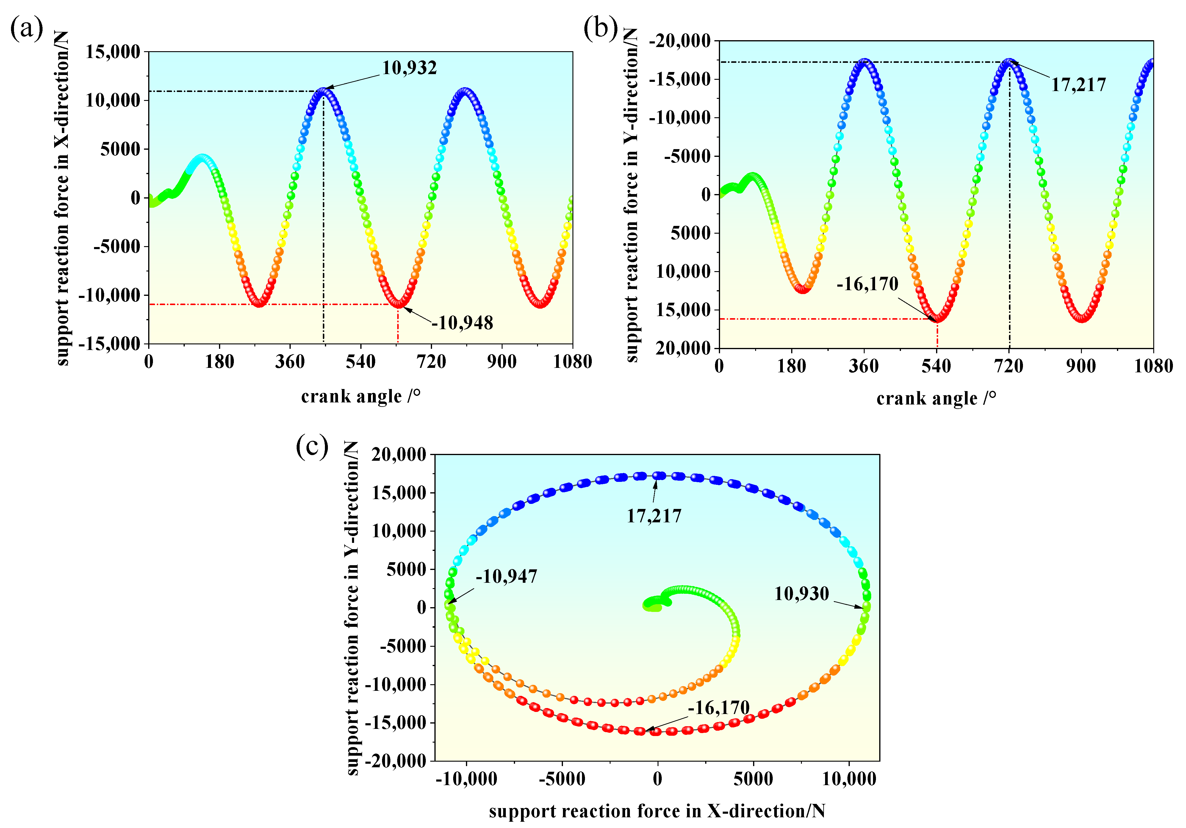
Table 2. The total simulation time is set to 0.4 s with 2000 time steps. The support reaction forces obtained from the simulation are shown in
Figure 5.
As shown in
Figure 5, the support reaction forces increase gradually with crankshaft rotation during the time interval of 0–0.05 s. A noticeable fluctuation occurs at 0.05 s, which is attributed to the piecewise definition of the crankshaft driving function, where 0.05 s corresponds to the transition point between the two step functions. During the period from 0.05 s to 0.1 s, the support reaction forces continue to increase and reach their maximum values after 0.1 s.
The maximum and minimum support reaction forces in the
direction are 10,932 N and −10,948 N, respectively, while those in the
direction are 17,217 N and −16,136 N, respectively. By plotting the support reaction force in the
direction against that in the
direction, the resultant trajectory shown in
Figure 5c is obtained. As illustrated in
Figure 5c, the resultant trajectory forms an approximately elliptical curve, with the major axis aligned with the
direction and the minor axis aligned with the
direction. This observation further indicates the inherent complexity associated with inertial force balancing in V-type marine high-pressure air compressors.
2.3.2. Pure Rigid-Body Dynamic Simulation After Balancing
In ADAMS, the gear meshing between the drive gears of the first-order and second-order balance weights is activated, and the crankshaft balance weight is also enabled. The gear contacts are modeled using an impact function combined with Coulomb friction. The corresponding contact parameters are listed in
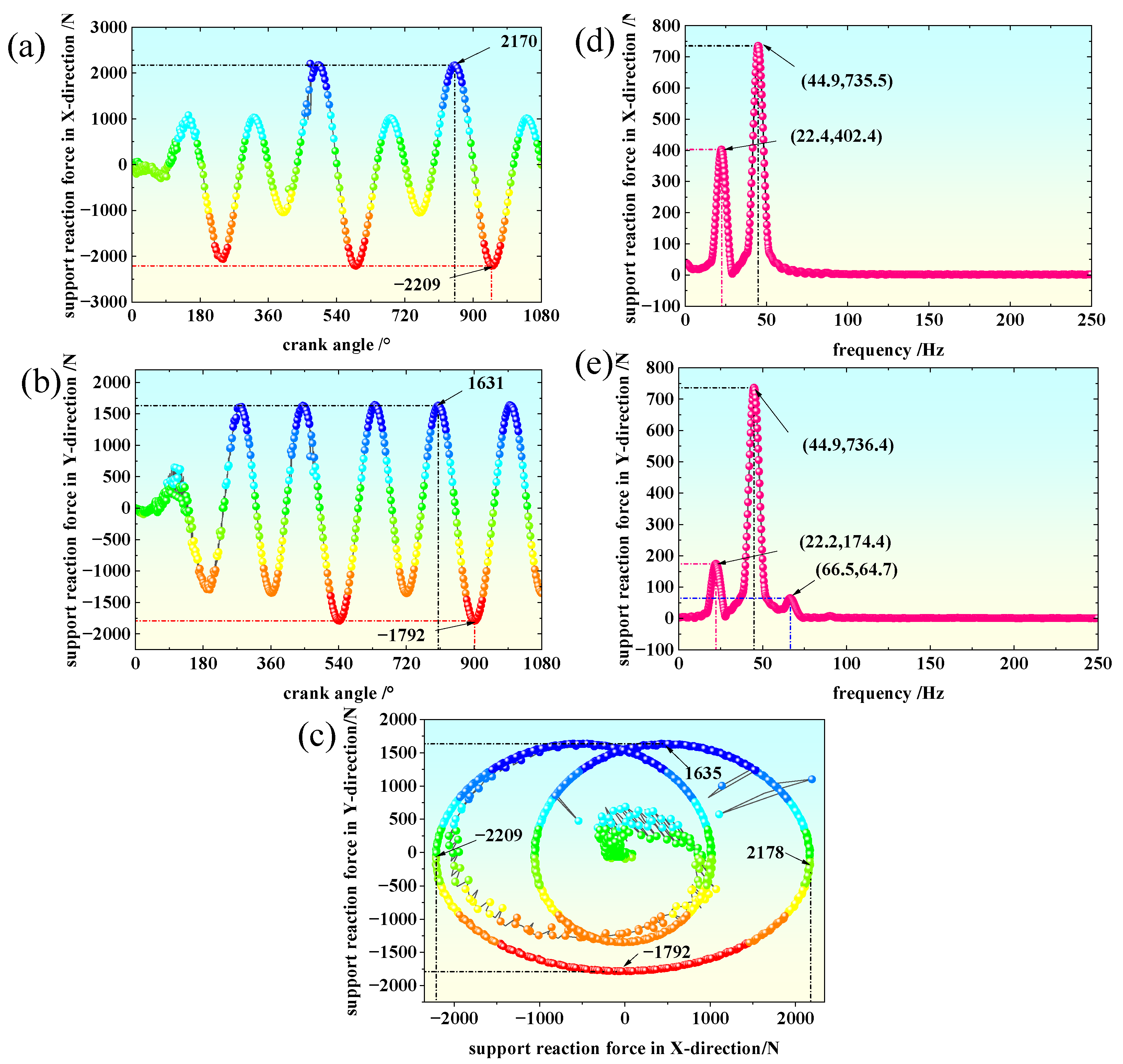
Table 3. The balanced support reaction forces obtained from the simulation are presented in
Figure 6.
As shown in
Figure 6a,b, the variation trend of the support reaction forces with crankshaft rotation during the time interval of 0–0.1 s is similar to that observed under the unbalanced condition, and the reaction forces reach their maximum values after 0.1 s. After balancing, the maximum and minimum support reaction forces in the x-direction are 2170 N and −2209 N, respectively, while those in the y-direction are 1631 N and −1729 N, respectively.
By plotting the support reaction force in the y-direction against that in the x-direction, the resultant trajectory shown in
Figure 6c is obtained. As illustrated in
Figure 6c, the resultant trajectory exhibits a crossed ring-like pattern and can be approximated by an elliptical shape, with the major axis aligned with the x-direction and the minor axis aligned with the y-direction.
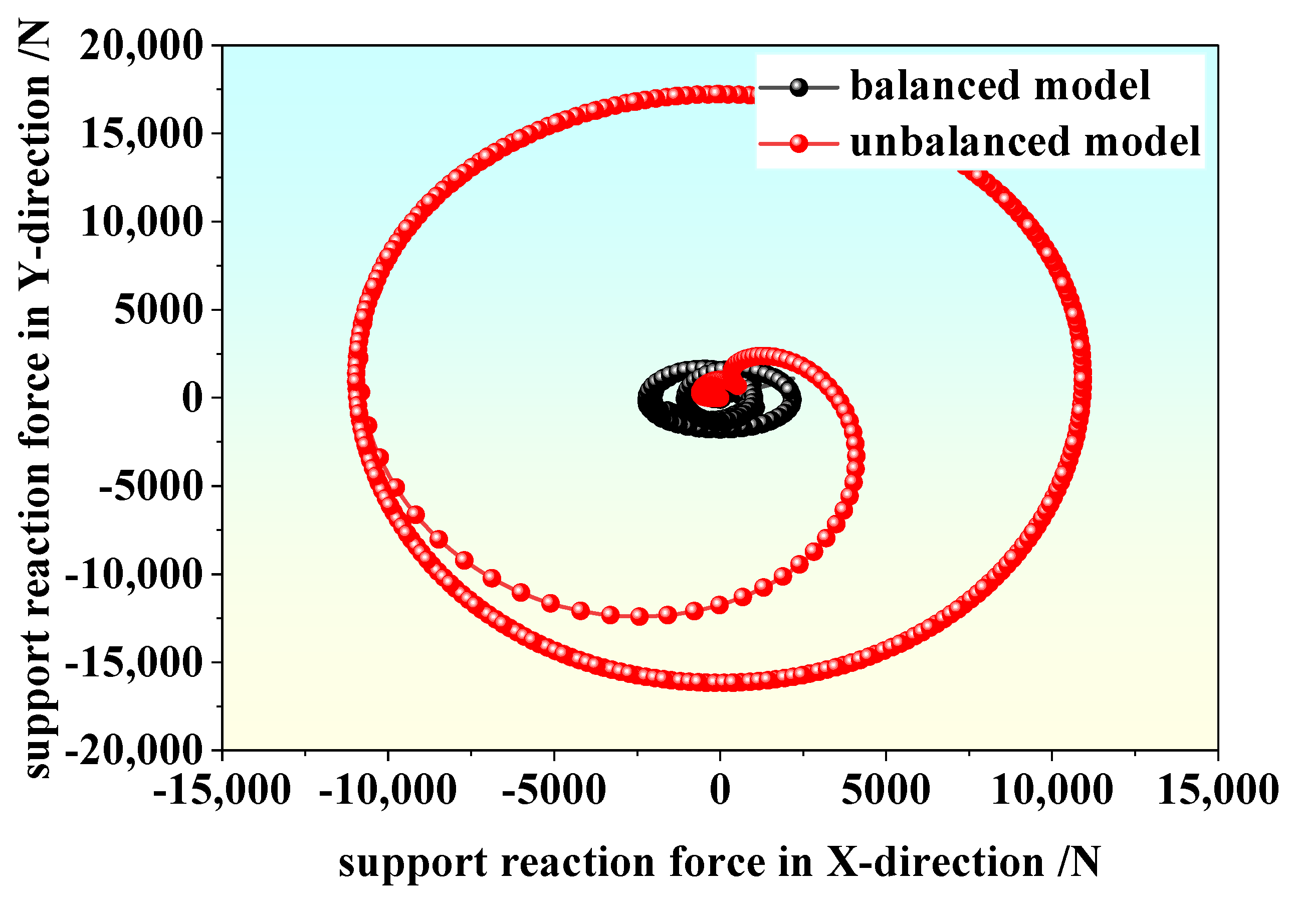
To facilitate a clearer comparative analysis of the inertial force magnitudes before and after balancing, the resultant forces in the x–y plane for both cases are presented in
Figure 7.
In summary, the inertial forces of the pure rigid-body crankshaft-connecting rod–piston system of the marine high-pressure air compressor are balanced using the counter-rotating gear system, with the balance weights determined from the theoretical calculations. After balancing, the inertial force in the direction is reduced by 80.15%, while that in the direction is reduced by 90.53%. It should be noted that, in addition to transmitting motion for the balance weights, the counter-rotating gear system also introduces additional rotating mass and meshing-induced excitation, which may affect the residual unbalance and support reaction responses of the system. Therefore, in the ADAMS dynamic model, the gear bodies as well as the meshing contact stiffness, damping, and friction parameters are explicitly considered so as to more realistically reflect the influence of the gear train on the overall dynamic behavior.
3. Dynamic Simulation Based on the Theory of Rigid–Flexible Coupling
3.1. Basic Theory of Rigid–Flexible Coupling
The integration of multibody dynamic simulation with structural finite element analysis, commonly referred to as rigid–flexible coupled simulation, has become a key approach for high-accuracy design and performance evaluation of modern complex electromechanical systems. In conventional multibody dynamic models, system components are typically treated as rigid bodies, thereby neglecting the influence of elastic deformation on the dynamic response of the system.
For marine high-pressure air compressors operating at high rotational speeds, slender components such as the crankshaft and connecting rods are subjected to alternating inertial loads, which can induce significant flexible deformation. These deformations alter the load transmission paths and magnitudes within the mechanism, leading to deviations in dynamic response and balancing effectiveness. Therefore, it is necessary to model the crankshaft and connecting rods of the marine high-pressure air compressor as flexible bodies, so as to identify more accurate balance masses and to achieve a more reliable evaluation of the balancing performance under realistic operating conditions.
In this study, the crankshaft and connecting rods are modeled as flexible bodies using a modal-superposition-based flexible body formulation. This approach enables an accurate representation of structural deformation effects while maintaining computational efficiency, thereby providing a solid foundation for rigid–flexible coupled dynamic analysis and subsequent balancing optimization. The displacement field of a flexible body is described by the nodal generalized coordinates
and the shape functions
[
10]:
where
denotes the generalized coordinate vector of node
. Based on Lagrange’s equations, the governing dynamic equation of the flexible body can be derived as:
where
are the mass, damping, and stiffness matrices, respectively;
is the generalized coordinate vector incorporating both rigid-body motion and elastic deformation; and
represents the external excitation vector, including gas forces, inertial forces, and bearing reaction forces. The mass matrix M, damping matrix C, and stiffness matrix K in the flexible-body dynamic equation are automatically generated through the finite element discretization and modal reduction processes of the key components in ANSYS. Since these matrices are high-dimensional and strongly dependent on the specific mesh discretization, their full entries are not listed in the manuscript. Instead, the present work retains the governing equation form and focuses on discussing their physical meaning and role in rigid–flexible coupled dynamic modeling.
It should be noted that the Coulomb friction model adopted in the gear contact modeling of this work is mainly used to represent the basic friction effect during contact transmission and is essentially a simplified formulation. In real compressor systems, more complex tribological processes may also exist, including lubrication-state variation, surface wear evolution, local temperature rise, and material contact nonlinearity. These factors may further influence vibration response and energy dissipation. Therefore, the present results are more suitable for comparative analysis of inertial force balancing and structural flexibility effects, rather than being interpreted as a full description of the complete tribological behavior.
3.2. Co-Simulation Between ANSYS and ADAMS
In this study, a widely accepted ANSYS–ADAMS co-simulation framework is employed to investigate the rigid–flexible coupled dynamic behavior of key components in the marine high-pressure air compressor. By integrating finite element analysis with multibody dynamic simulation, this approach enables an accurate description of the elastic deformation of flexible components as well as their dynamic response under large rigid-body motions. Consequently, the limitations of conventional pure rigid-body multibody dynamic models under high-speed and high-inertial-load operating conditions can be effectively overcome, thereby significantly enhancing the engineering reliability of the simulation results.
Specifically, high-fidelity finite element models of critical components such as the crankshaft and connecting rods are first established in ANSYS, followed by modal analysis and modal reduction to extract the dominant low-order modes. The resulting flexible body models are then imported into ADAMS and integrated with the remaining rigid bodies and kinematic constraints to construct a complete rigid–flexible coupled multibody dynamic model. Under realistic operating conditions, appropriate driving functions, external loads, and boundary conditions are applied to analyze the system’s dynamic response, inertial force transmission characteristics, and variations in support reaction forces [
21,
22,
23].
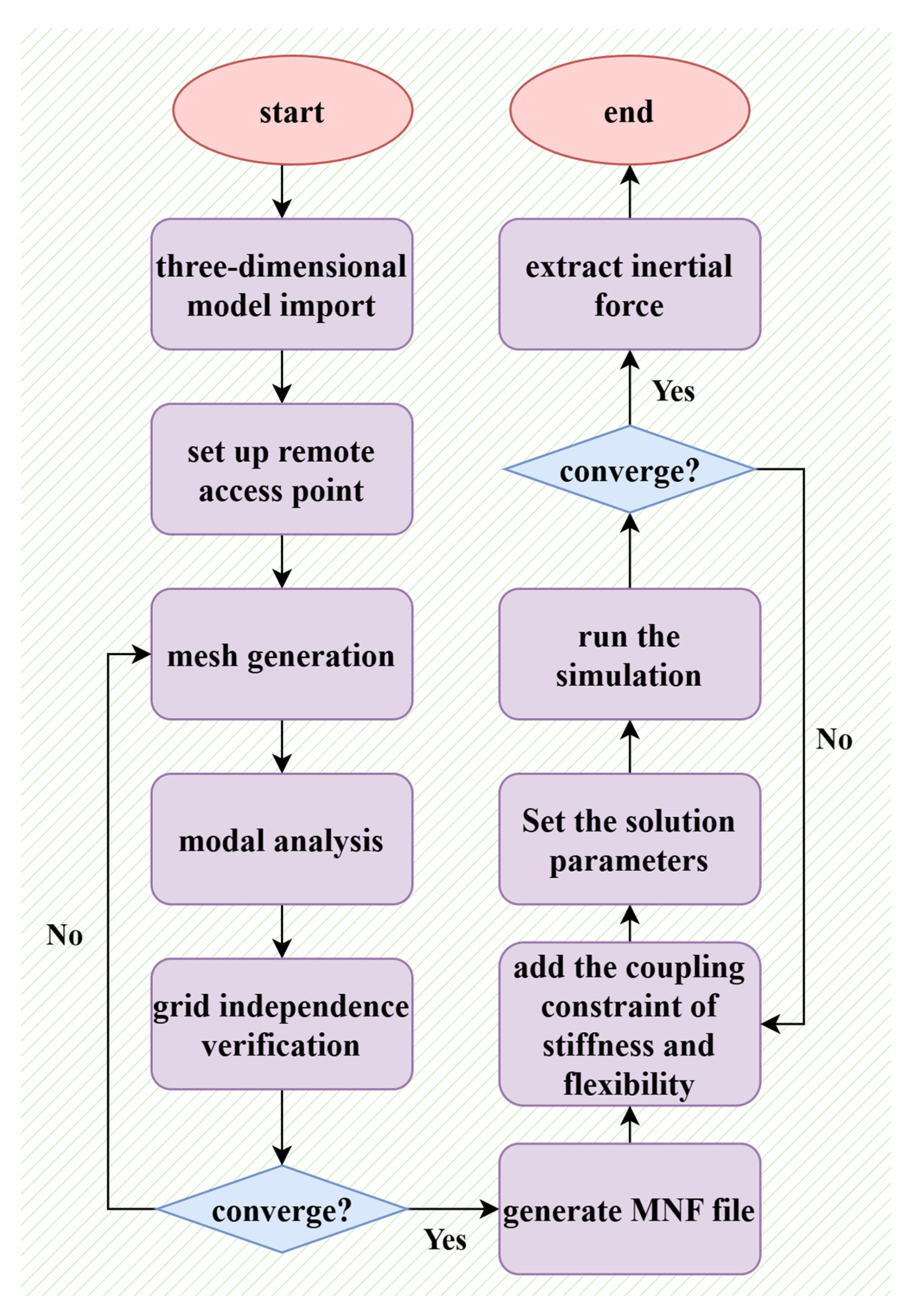
The adopted co-simulation workflow is illustrated in
Figure 8. This procedure establishes a closed-loop process encompassing geometric modeling, flexible body generation, rigid–flexible coupled dynamic simulation, and result validation, providing a high-confidence numerical foundation for subsequent balance mass optimization and vibration control assessment.
In ANSYS Workbench, finite element models of key components such as the crankshaft and connecting rods are established, followed by mesh generation and modal analysis. Modal neutral files (MNFs), containing modal shapes and natural frequency information, are then extracted for subsequent flexible body modeling in multibody dynamic simulations. Particular attention is paid to the definition of structural parameter control (SPC) points, also referred to as remote points, during the finite element modeling stage. The MNF-based flexible-body model adopted in this study is mainly used to capture the influence of the structural flexibility of key components on the system’s dynamic response. No experimentally identified explicit modal damping ratio was introduced in the current model; instead, local dissipation is mainly represented by the damping parameter in the gear meshing contact model. Therefore, the present results mainly reflect the influence of structural flexibility on inertial excitation transmission, while more accurate structural damping modeling still requires further experimental support.
This is because flexible bodies imported into ADAMS cannot be connected using fixed joints or revolute joints in the same manner as rigid bodies, and no selectable geometric markers are inherently available. Therefore, when generating the MNF files, connection markers for kinematic joints and load application must be explicitly defined in advance within ANSYS. By introducing remote points, appropriate kinematic constraints and force transmission paths between the flexible bodies and the remaining rigid components can be established, thereby ensuring the accuracy and numerical stability of the rigid–flexible coupled dynamic model.
ANSYS Workbench and MSC ADAMS were jointly employed in this study to perform the rigid–flexible coupled analysis. ANSYS Workbench was mainly used for finite element modeling of key components such as the crankshaft and connecting rods, modal analysis, and generation of modal neutral files (MNF). MSC ADAMS was mainly used for multibody dynamic modeling of the crank–slider and balancing system, definition of gear meshing relationships, extraction of support reaction forces, and optimization analysis through the Insight module. This software combination provides a good balance between the accuracy of structural flexibility representation and the computational efficiency of system-level dynamic simulation, and is therefore suitable for the inertial force balancing problem addressed in this study. The hardware and software computing environments used in this study are shown in
Table 4.
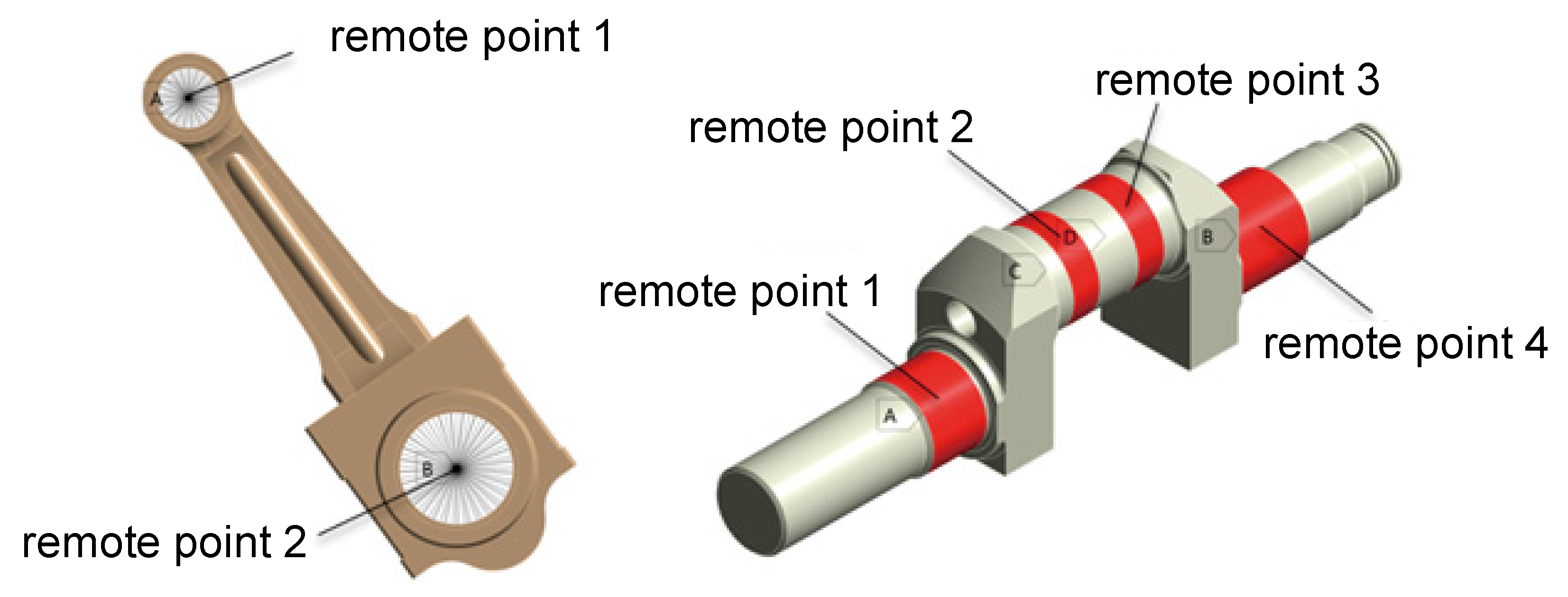
In this study, dedicated remote points are defined for both the connecting rods and the crankshaft. The corresponding locations and configurations of these remote points are illustrated in
Figure 9.
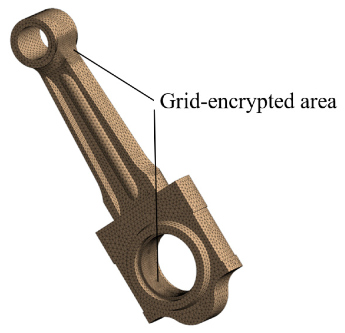
During finite element analysis, the quality of the mesh has a decisive influence on simulation accuracy. When generating the MNF file, the mesh size and modal deformation characteristics are parameterized, where the mesh parameters are selected as design variables, and the minimization of modal deformation is defined as the optimization objective. A parametric optimization is then performed to obtain an optimal mesh configuration, as shown in
Figure 10, and the corresponding results are summarized below.
3.2.1. Mesh Independence Verification of the Connecting Rod
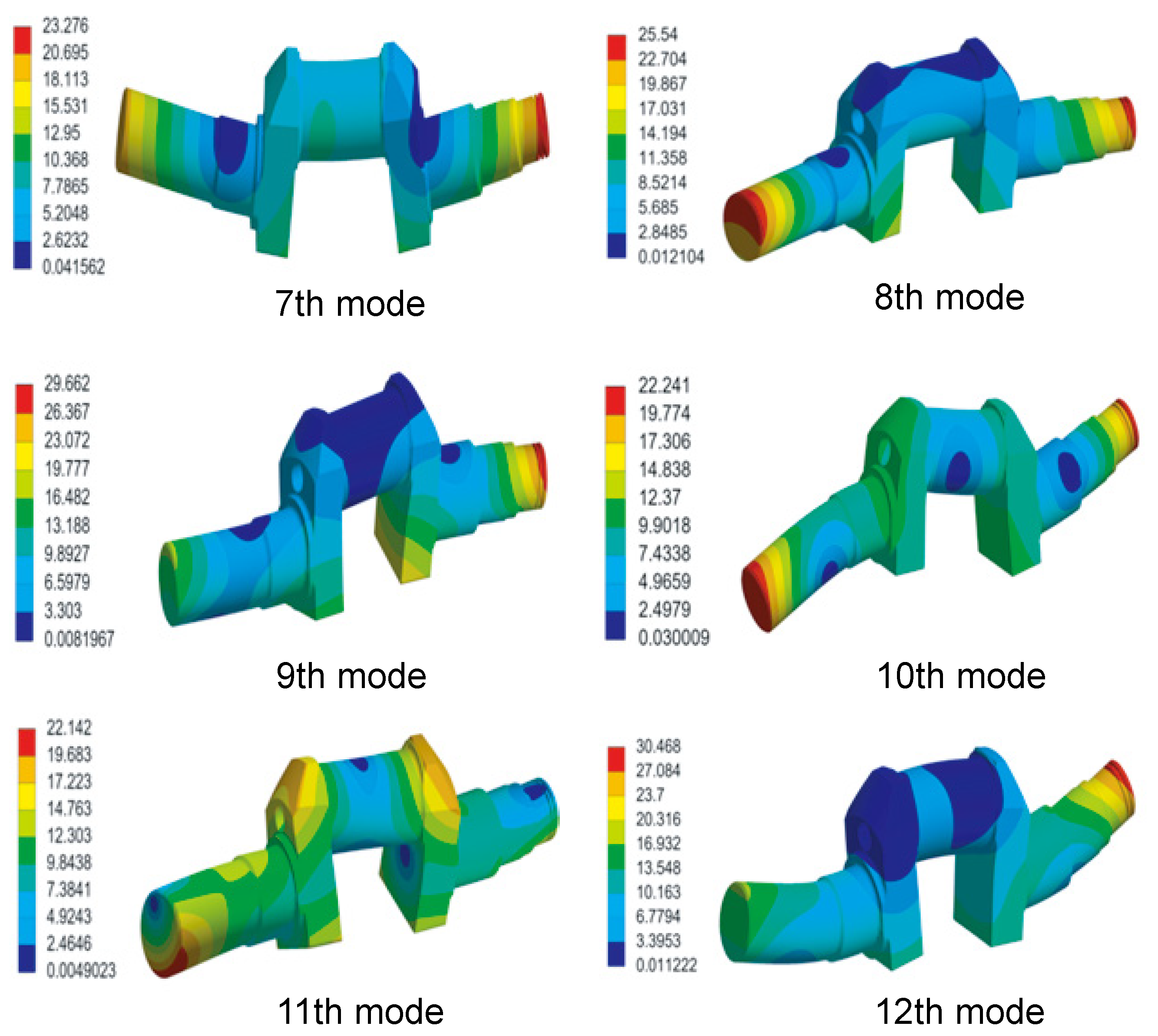
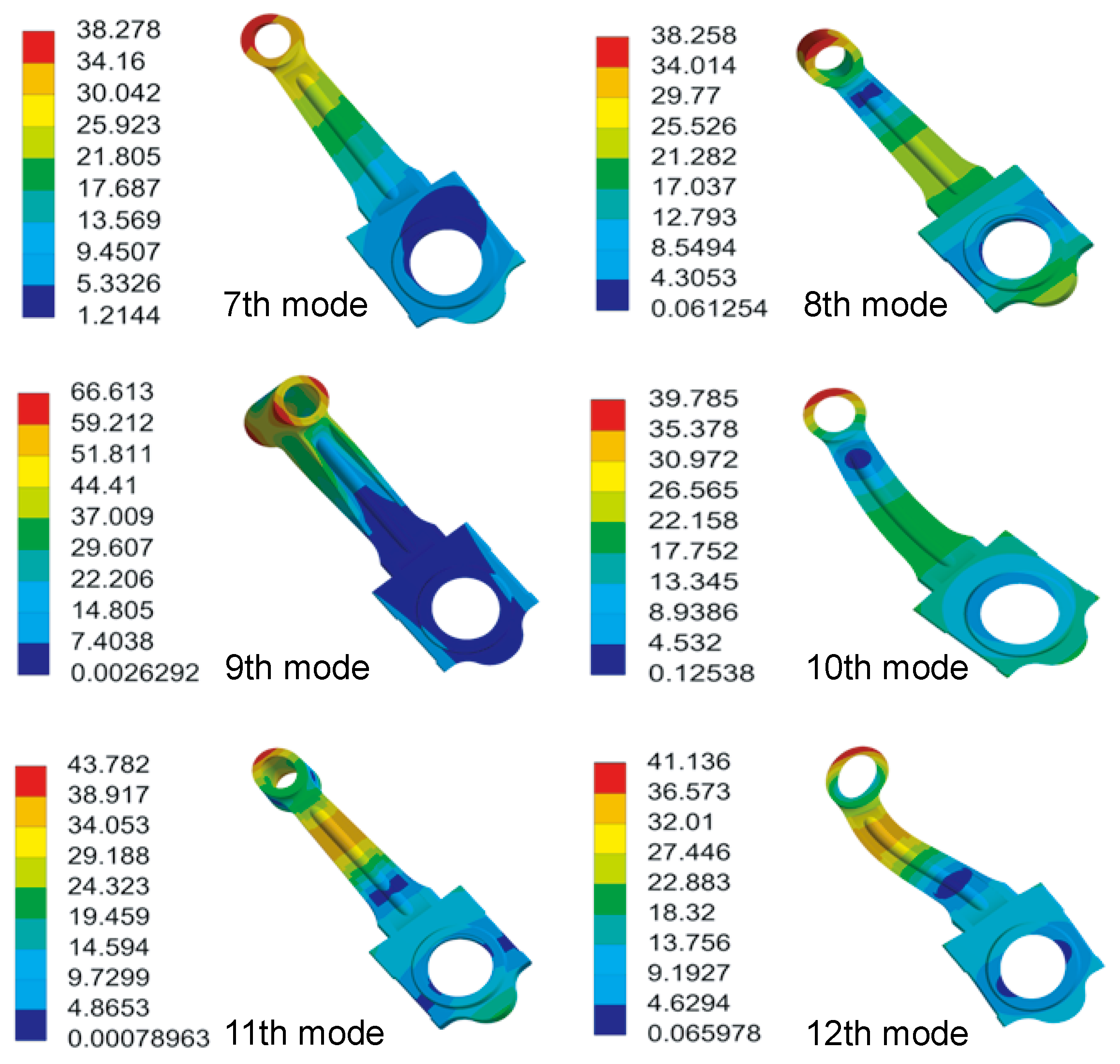
A free modal analysis is performed for the connecting rod, and a total of 32 modes are extracted. Since the first six modes correspond to rigid-body modes, the modal deformations from the 7th to the 12th modes are selected as the optimization objectives for mesh independence verification. The variation in these modal characteristics with respect to element size is illustrated in
Figure 11, and the results of the mode shape are shown in
Figure 12.
As indicated by the mode shapes, the 7th to 12th modes effectively cover the principal loading directions experienced by the connecting rod during operation, demonstrating that the selected modes are representative and that the mesh independence verification is reasonable.
Considering the convergence behavior with respect to mesh size (
Table 5) and the associated computational expense, an element size of 3 mm is adopted. The resulting model comprises 172,300 elements, based on which the modal analysis is performed and the MNF file is generated.
3.2.2. Mesh Independence Verification of the Crankshaft
Using the same mesh independence verification approach (
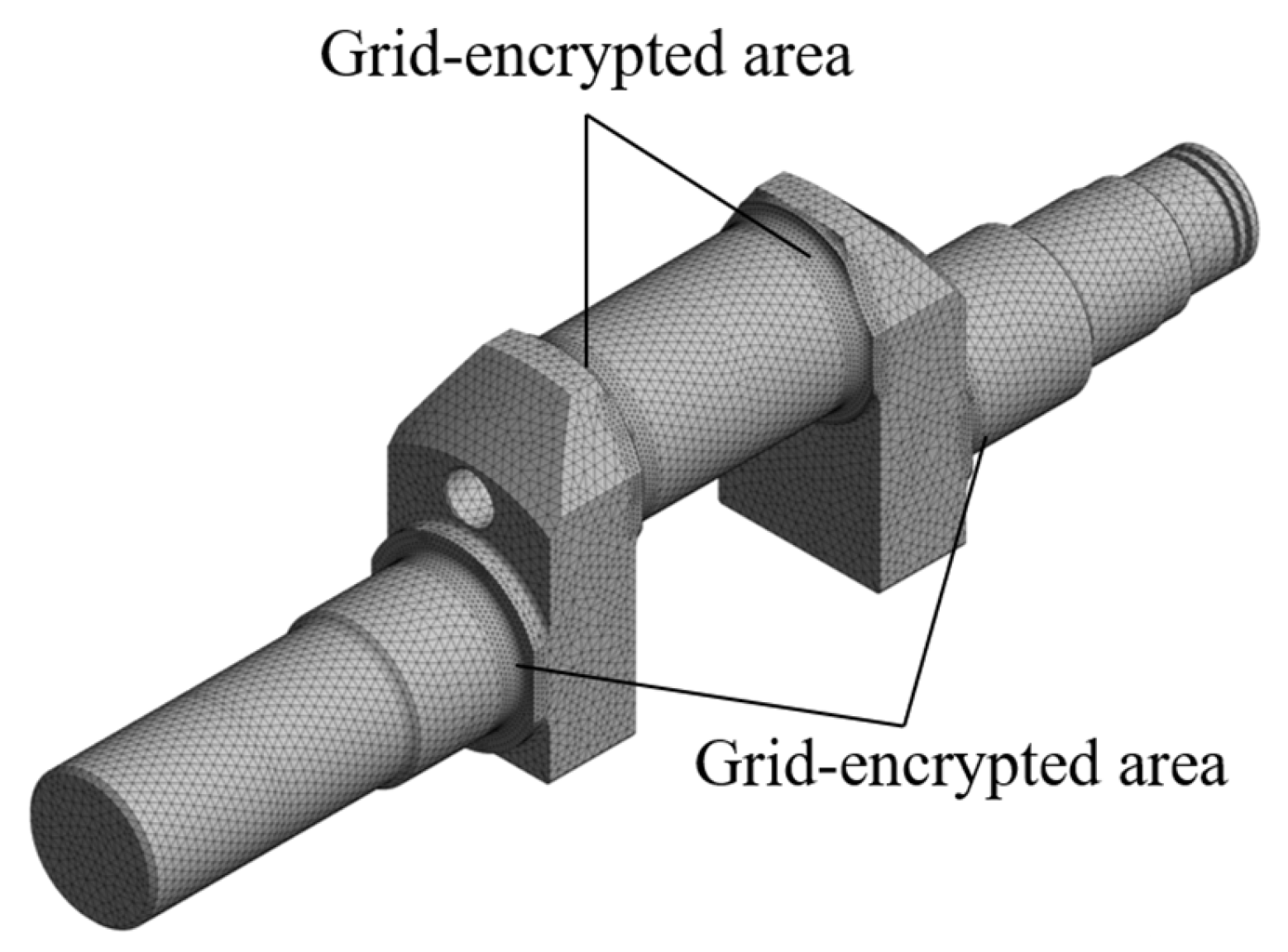
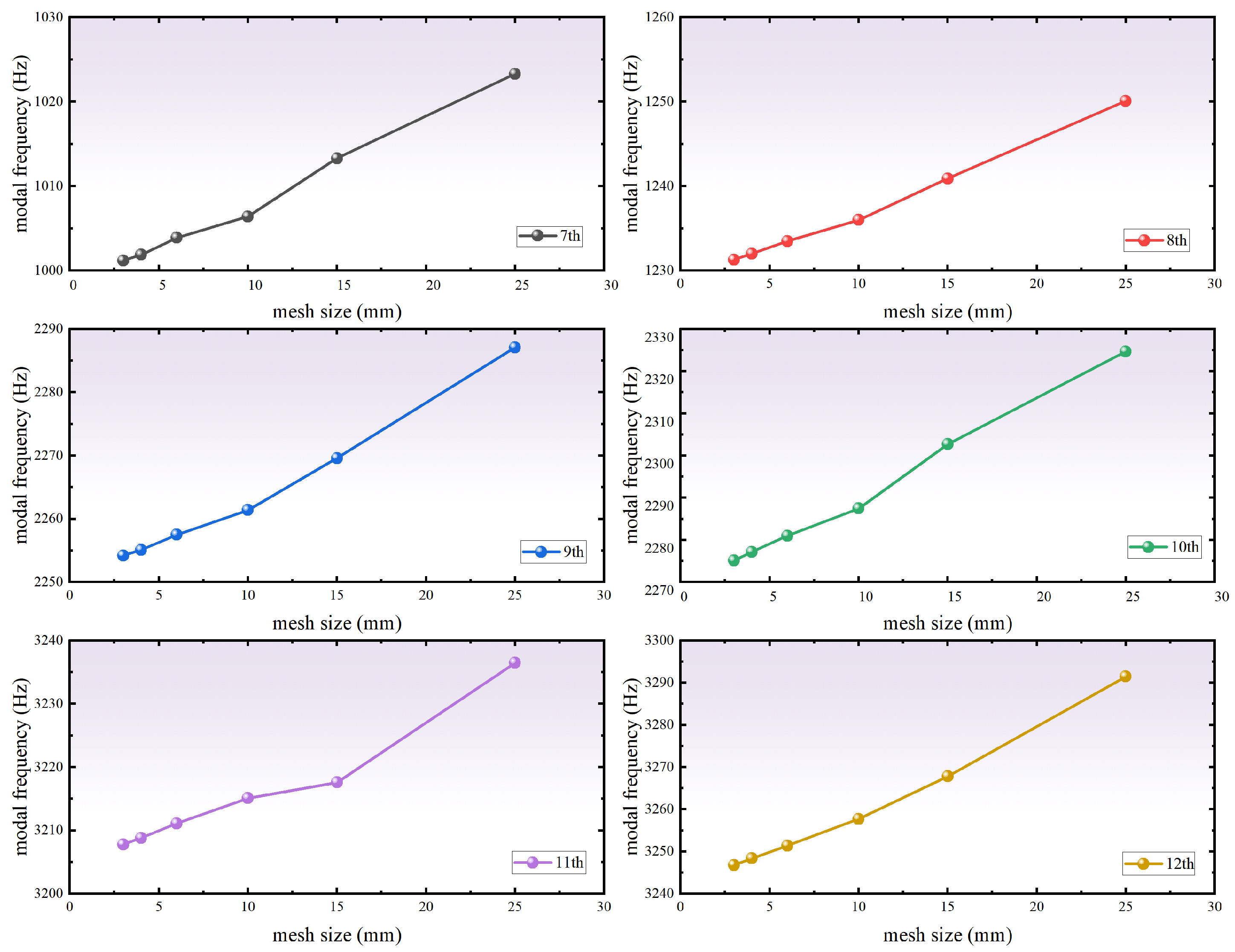
Table 6) as that applied to the connecting rod, the crankshaft is discretized with a mesh size of 4 mm. As shown in
Figure 13, mesh refinement is performed on the locations of the crankshaft where stress concentration is prone to occur, and a total of 217,013 elements are obtained through final meshing. The corresponding variation in modal results with mesh size is shown in
Figure 14 and
Figure 15.
3.3. Rigid–Flexible Coupled Dynamic Simulation
The MNF files of the crankshaft and connecting rods are imported into ADAMS multibody dynamics software to replace the original rigid components. Kinematic constraints are then defined between the crankshaft and bearings (revolute joints), the connecting rods and pistons (revolute joints), and the pistons and cylinder liners (translational joints). The balance mass values and crankshaft motion parameters are kept consistent with those used in the pure rigid-body simulations to ensure comparability of the results.
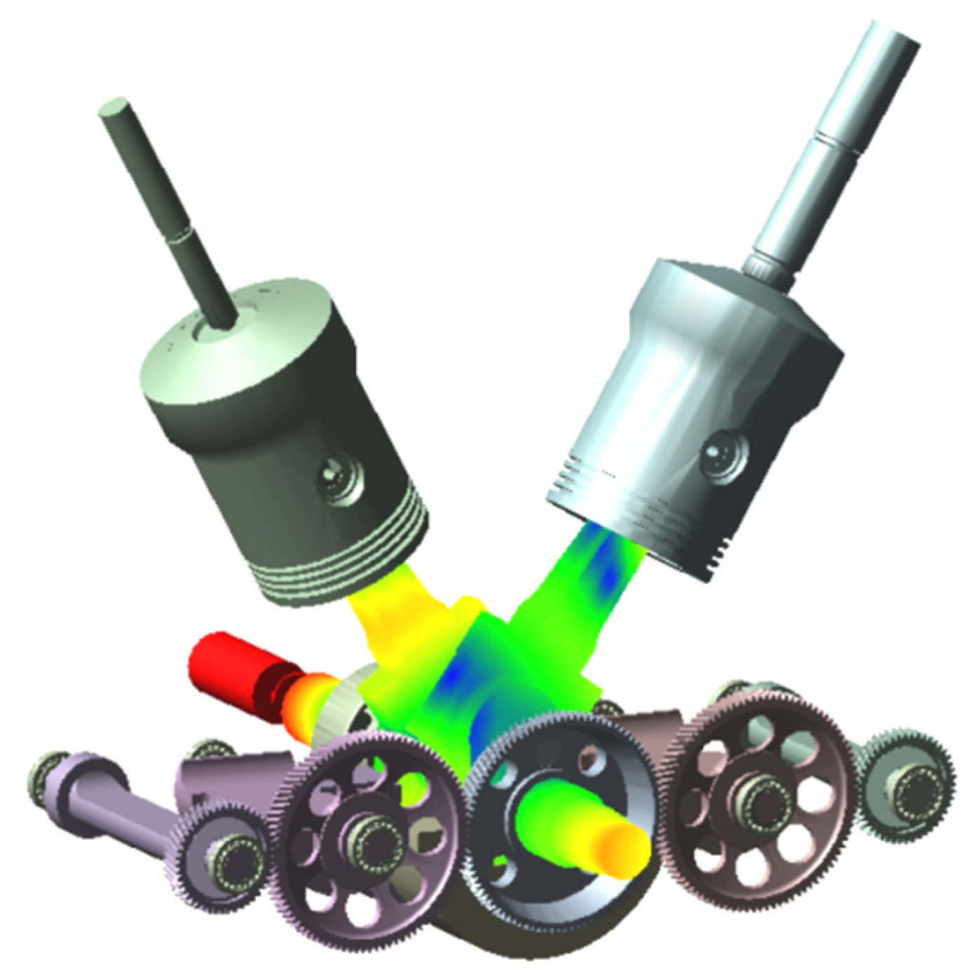
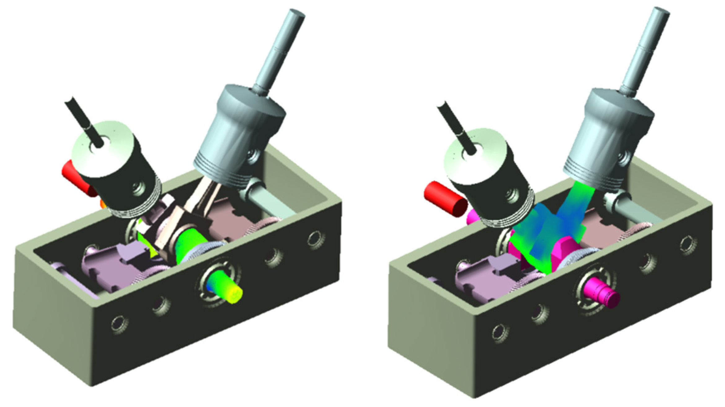
Based on these settings, rigid–flexible coupled dynamic simulations are performed. The resulting rigid–flexible coupled multibody model incorporating the imported MNF files is shown in
Figure 16.
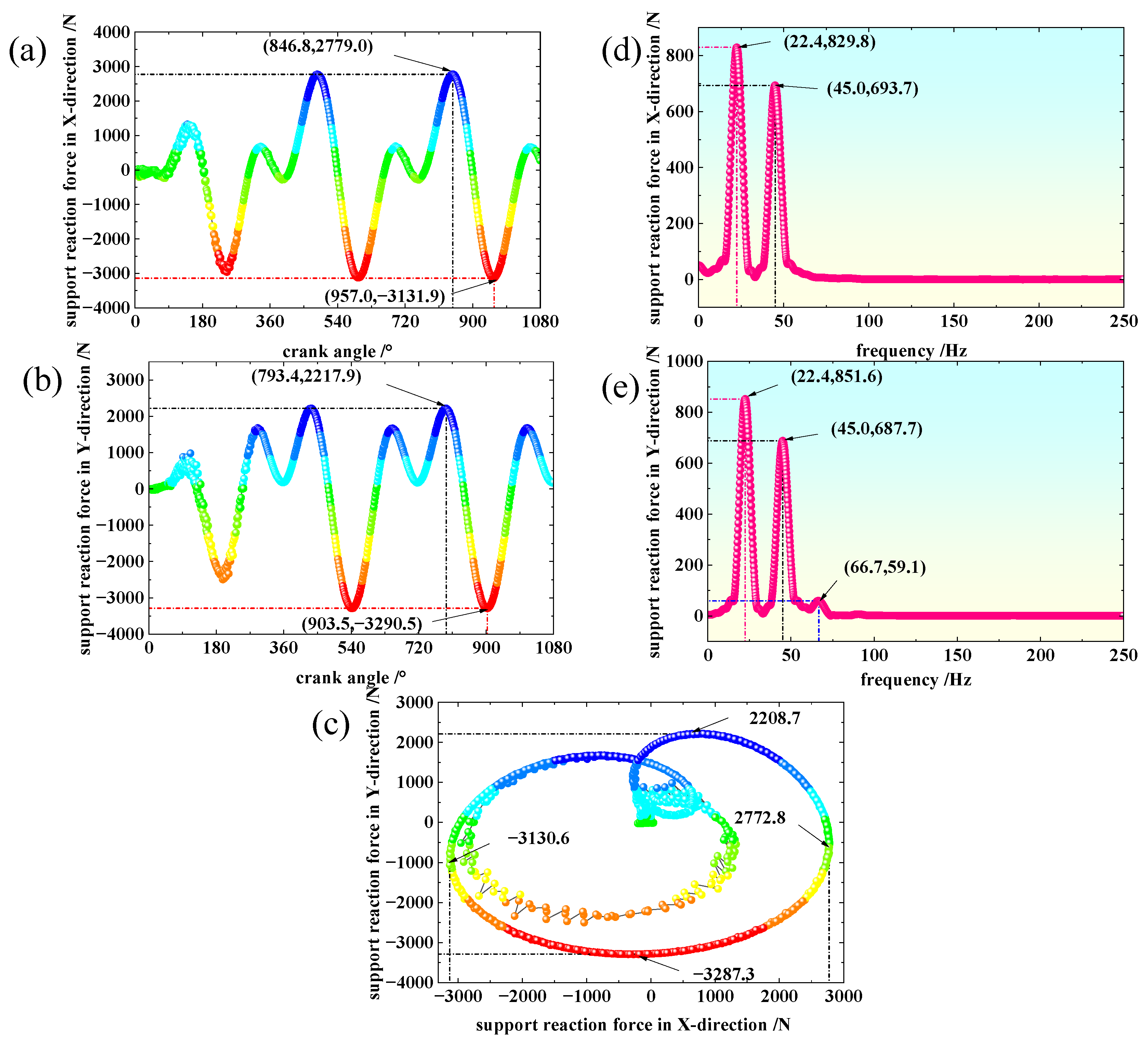
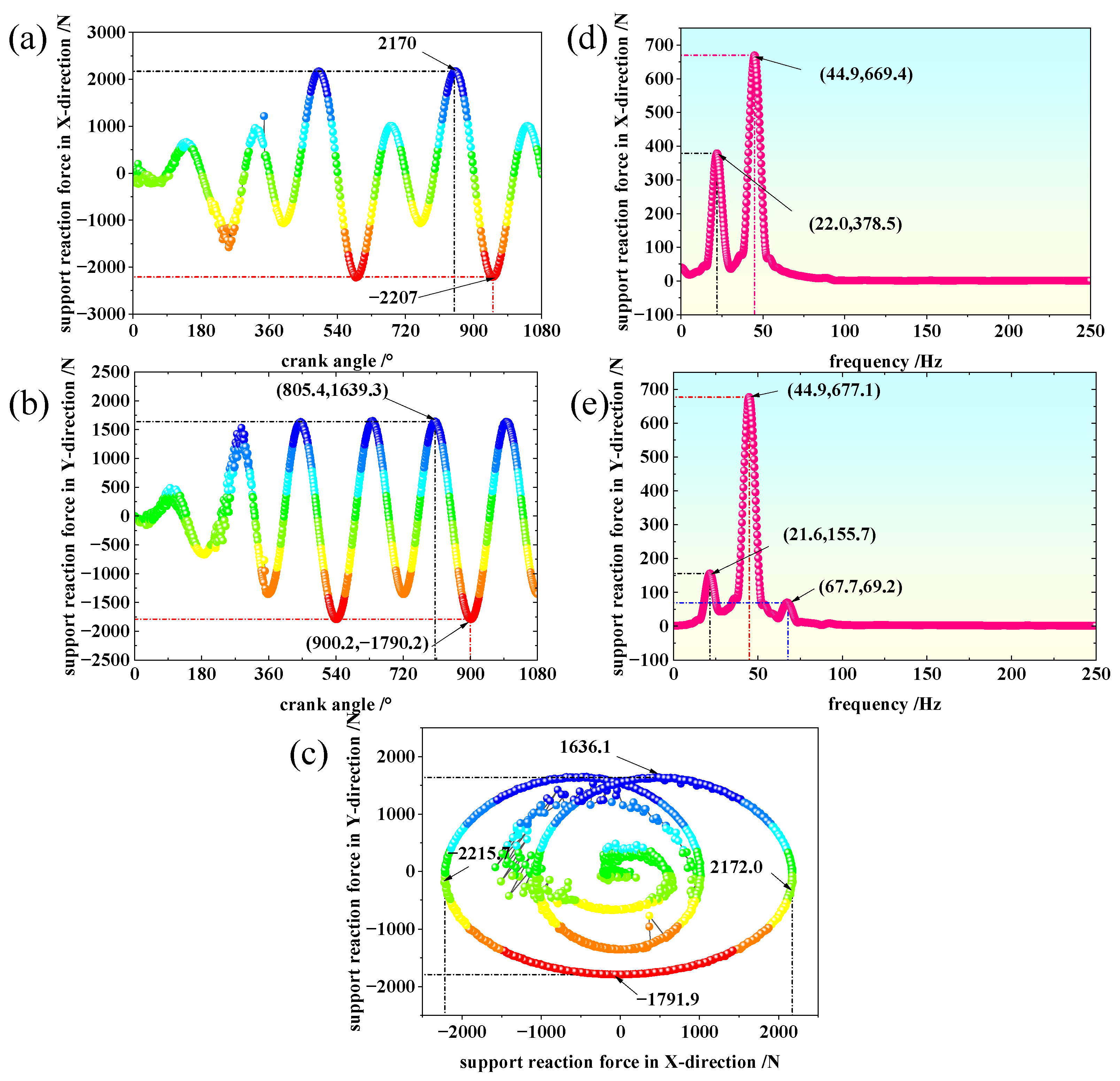
Rigid–flexible coupled dynamic simulations are conducted separately for the connecting rod and crankshaft models. The resulting base reaction forces are extracted and compared, as illustrated in
Figure 17 and
Figure 18. The simulation results indicate that when crankshaft flexibility is taken into account, the fluctuation characteristics of the bearing reaction forces are significantly altered due to bending deformation. Compared with the pure rigid-body model, the inclusion of crankshaft flexibility leads to a reduction of approximately 6% in the first-order excitation force amplitude and about 9% in the second-order excitation force amplitude in the x-direction. In the y direction, the first-order and second-order excitation force amplitudes are reduced by approximately 10.7% and 8%, respectively. However, the amplitude of the third-order excitation force increases by about 7%, indicating that crankshaft flexibility provides a damping effect on low-order vibrations while potentially enhancing higher-order dynamic responses.
When only the flexibility of the connecting rod is considered, the dynamic characteristics of the bearing reaction forces are affected more significantly owing to the pronounced influence of bending deformation on the load transmission path. Compared with the pure rigid-body model, the first-order excitation force amplitude in the x-direction increases by approximately one time, whereas the second-order excitation force amplitude decreases by about 5.7%. In the y-direction, the first-order and second-order excitation force amplitudes are reduced by approximately 10.7% and 6.6%, respectively. Meanwhile, the third-order excitation force amplitude increases by about 8.7%. These results demonstrate that connecting rod flexibility exerts a bidirectional and more pronounced influence on the system’s dynamics, particularly amplifying the first-order load in the x-direction.
Overall, the above analyses reveal that treating key components as flexible bodies rather than rigid bodies in the dynamic simulation of the crankshaft-connecting rod system of a marine high-pressure air compressor can significantly alter the predicted bearing reaction forces. Crankshaft flexibility mainly contributes to vibration reduction at low orders, whereas the effect of connecting rod flexibility is more complex and severe, especially in terms of first-order excitation in the x-direction. When both effects are combined, higher-order (third-order) vibration responses may be further excited.
Consequently, the balance masses of the first-order and second-order balance weights, as well as the crankshaft balance weight, determined based on the pure rigid-body model using the counter-rotating gear system, require further optimization to achieve more effective inertial force balancing under realistic operating conditions.
To obtain a more accurate evaluation of the excitation forces transmitted to the compressor casing during operation, both the crankshaft and the connecting rods are modeled as flexible bodies, and a rigid–flexible coupled dynamic simulation is performed, as shown in
Figure 19. The simulation parameters are kept identical to those used in the pure rigid-body simulations, and the corresponding results are presented in
Figure 20.
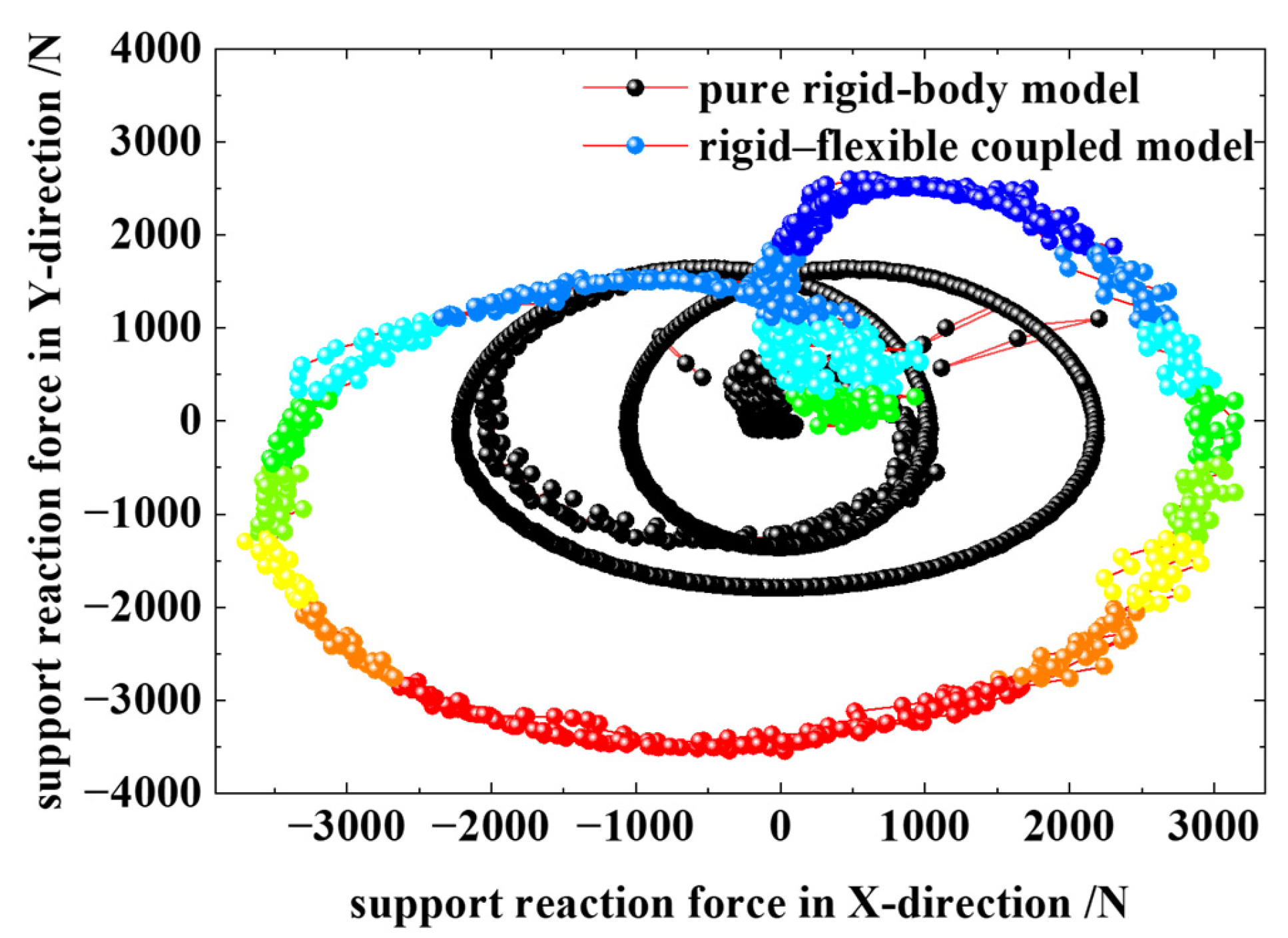
As shown in
Figure 20, when both the crankshaft and connecting rods are treated as flexible bodies, the bearing reaction forces are generally higher than those predicted by the pure rigid-body model. This further confirms the necessity of re-optimizing the balance masses obtained from rigid-body-based calculations using rigid–flexible coupled simulation results in order to achieve more effective balancing of the casing excitation forces in marine high-pressure air compressors.
Compared with the pure rigid-body model, the rigid–flexible coupled model predicts higher support reaction forces when both the crankshaft and the connecting rods are treated as flexible bodies. This difference indicates that the elastic deformation of the key transmission components alters the internal load transfer path and the phase relationship of dynamic forces, thereby amplifying the excitation transmitted to the casing. In particular, the crankshaft flexibility mainly affects the low-order bending-related response, whereas the connecting rod flexibility has a stronger influence on load redistribution along the slider–crank path. When both effects are combined, the discrepancy between the rigid-body-based balancing design and the actual dynamic behavior becomes more pronounced. Therefore, the results in
Figure 19 further justify the necessity of re-optimizing the balance mass based on the rigid–flexible coupled model rather than relying only on the traditional rigid-body assumption.
4. Optimization of Balance Mass Under Rigid–Flexible Coupled Conditions
To achieve optimal inertial force balancing performance under rigid–flexible coupled conditions, an optimization model is established with the objective of reducing the resultant support reaction forces transmitted to the compressor casing in the directions. The balance masses of the crankshaft counterweight, the first-order balance weight, and the second-order balance weight are selected as the design variables, since these parameters directly govern the amplitudes and phase relationships of the rotating, first-order, and second-order inertial forces, respectively. The optimization objectives are defined as the minimization of the absolute peak values of the support reaction forces in both directions, considering that peak loads are closely related to structural fatigue, vibration transmission, and noise excitation in marine compressor systems. Meanwhile, practical installation constraints are imposed to ensure that the balance masses do not exceed the available spatial limits.
To improve the inertial force balancing performance under rigid–flexible coupled conditions, the mass of the crankshaft counterweight, the first-order balance weight, and the second-order balance weight are taken as design variables, while minimizing the peak support reaction forces in the x and y directions is selected as the optimization objective. Meanwhile, constraints such as the allowable mass range and installation space limitation are imposed. The resulting multi-objective optimization model can be expressed as Equations (15) and (16).
subject to
where
,
, and
denote the masses of the crankshaft counterweight, first-order balance weight, and second-order balance weight, respectively, and
and
represent the support reaction forces in the x and y directions.
The optimization procedure is implemented using the Design of Experiments (DOE) and optimization modules in ADAMS/Insight. An optimal Latin hypercube sampling (OLHS) strategy is employed to efficiently explore the design space with a limited number of samples while maintaining favorable space-filling characteristics. Based on the sampled data, surrogate response surface models are constructed to approximate the nonlinear relationships between the balance mass parameters and the resulting support reaction forces. To reduce computational cost and improve optimization efficiency, a surrogate-based optimization framework is adopted instead of direct optimization using high-fidelity rigid–flexible coupled simulations. Subsequently, a gradient-based Generalized Reduced Gradient (GRG) algorithm is applied to solve the constrained multi-objective optimization problem and determine the optimal balance mass configuration. The GRG (Generalized Reduced Gradient) algorithm adopted in this study is a gradient-based solution method for constrained nonlinear optimization problems. After a surrogate model is constructed based on DOE samples, the GRG algorithm iteratively updates the design variables by evaluating the reduced gradient within the feasible region defined by the constraints, until the objective functions converge. In this way, the optimal mass combination that yields smaller peak support reaction forces can be obtained.
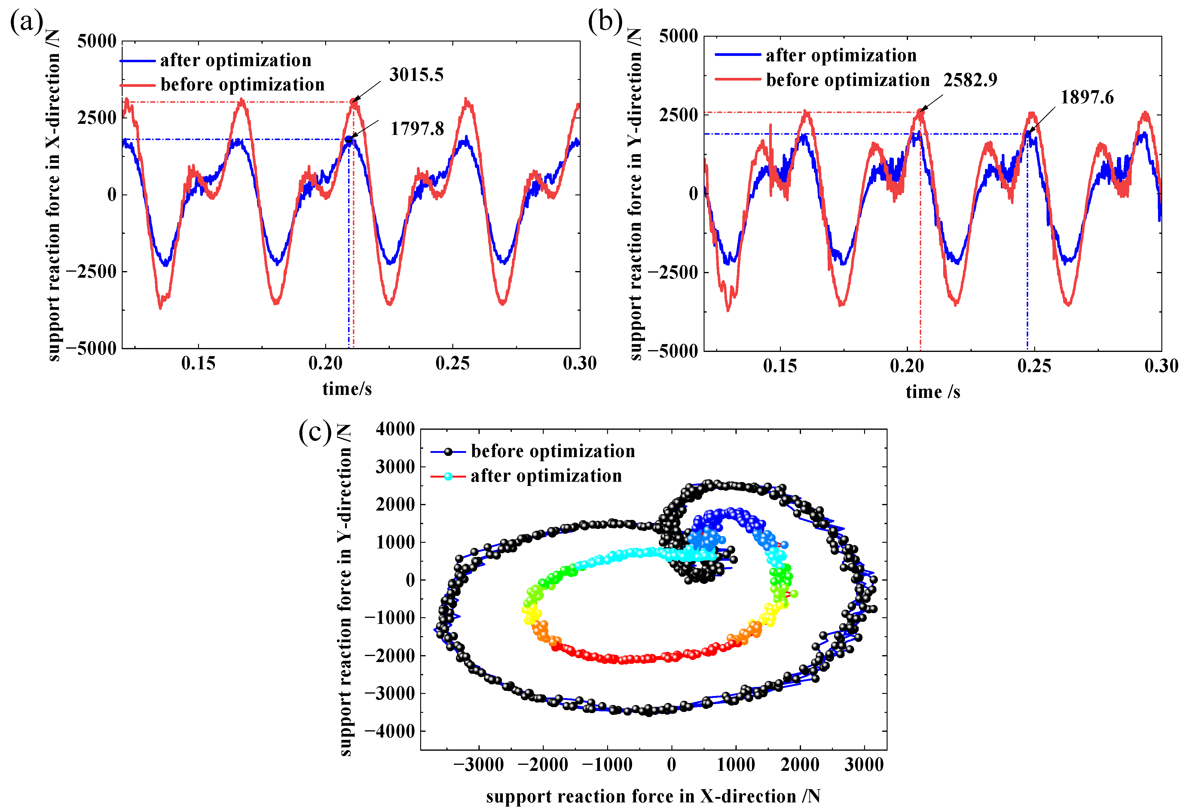
To evaluate the effectiveness of the proposed optimization framework, dynamic simulations are performed to compare the balancing performance obtained using theoretically calculated balance mass
es with that achieved after optimization. The simulation results, as shown in
Figure 21, indicate that the optimized balance mass
es significantly reduce the peak support reaction forces in both directions under rigid–flexible coupled conditions. Furthermore, the optimized balance mass values deviate noticeably from those derived based on pure rigid-body assumptions, highlighting the limitations of traditional rigid-body-based balancing methods when component flexibility is considered. These results demonstrate that incorporating rigid–flexible coupled dynamics into the balance mass optimization process is essential for accurately predicting inertial force transmission and for achieving effective vibration reduction in marine high-pressure air compressors.
As shown in
Figure 21, after optimization of the balance mass
es, the peak support reaction force in the x-direction is reduced from 3015.5 N to 1797.8 N, corresponding to a reduction of 40.4%. In the y-direction, the peak support reaction force decreases from 2582.9 N to 1897.6 N, achieving a reduction of 26.5%. A comparison of the key parameters before and after optimization is summarized in
Table 7. The optimization results demonstrate that, by appropriately adjusting the balance mass configuration, the inertial force excitation can be effectively suppressed without a significant increase in the overall structural weight.
5. Conclusions
This study systematically derives analytical expressions for the rotating inertial force as well as the first- and second-order reciprocating inertial forces of a marine V-type high-pressure air compressor, and further improves the resultant formulation of the first-order reciprocating inertial force by accounting for the cylinder bank angle. Based on these developments, an inertial force balancing design approach using a counter-rotating gear system is proposed and implemented, providing a practical theoretical tool for inertial force evaluation and preliminary balancing.
A rigid–flexible coupled multibody dynamic model of the crank-connecting rod mechanism is then established to incorporate the flexibility of key components. Comparative simulations demonstrate that, compared with the pure rigid-body model, the rigid–flexible coupled model captures the fluctuation characteristics of bearing/base reaction forces more realistically. In particular, the inclusion of crankshaft and connecting rod flexibility leads to notable changes in both the amplitudes and spectral features of the reaction forces, thereby improving the engineering fidelity of balancing assessment.
On the basis of the rigid–flexible coupled framework, a multi-objective optimization of balance weight masses is performed in ADAMS/Insight, with the peak base/casing reaction forces in the directions defined as the optimization objectives. The optimized configuration reduces the peak reaction force by 40.4% in the direction and by 26.5% in the direction, effectively suppressing inertial excitation without a significant increase in structural mass and substantially reducing the workload associated with balance mass selection in practical engineering applications.
Overall, this work establishes an integrated methodology comprising theoretical analysis, balancing design, high-fidelity simulation, and parameter optimization for inertial force balancing of marine high-pressure air compressors. The proposed framework balances theoretical rigor and engineering practicality, and can serve as a useful reference for low-vibration design and vibration control of similar reciprocating machinery.
For shipboard applications, vibration generated by the compressor can be transmitted through the mounting supports to the base, connected piping, nearby auxiliary equipment, and local deck-supporting structures, thereby affecting structural reliability, cabin noise, and crew comfort. By reducing the support reaction force at the source, the present methodology contributes to low-vibration design of marine compressor systems. Moreover, although the present work is carried out for a marine V-type high-pressure air compressor, the proposed workflow can also be extended to other high-speed reciprocating compressors and analogous crank–slider machinery in which inertial force balancing and component flexibility are both important.
Although the present study demonstrates the effectiveness of the proposed rigid–flexible coupled balancing and optimization framework, several limitations remain. Experimental validation of the simulated support reaction forces and the optimized balance mass configuration has not yet been completed. In addition, frequency response analysis, chassis/foundation structural response, and more detailed friction/valve dynamics modeling were beyond the current scope. These issues will be addressed in future work to further improve the physical fidelity and engineering applicability of the model.
Author Contributions
Conceptualization, J.F. and J.L.; Software, J.F.; Validation, H.Z. and J.L.; Formal analysis, H.Z.; Writing—original draft, J.F.; Writing—review & editing, H.Z.; Supervision, J.L. and X.J.; Project administration, J.L. and X.J. All authors have read and agreed to the published version of the manuscript.
Funding
This paper was supported by the Natural Science Foundation of Chongqing, China (CSTB2023NSCQ-LMX0031).
Data Availability Statement
The original contributions presented in this study are included in the article. Further inquiries can be directed to the corresponding author.
Acknowledgments
The authors acknowledge the use of Chat-GPT(5.4) solely for the purpose of improving the English language expression and correcting grammatical errors. The scientific content, analysis, and conclusions are entirely the work of the authors, who have thoroughly reviewed and approved the final manuscript.
Conflicts of Interest
The author Jun Feng was employed by the company Hengyuan Technology Co., Ltd., China State Shipbuilding Corporation. The remaining authors declare that the research was conducted in the absence of any commercial or financial relationships that could be construed as potential conflicts of interest.
References
- Chai, K.; Hu, J.; Lou, J. Equilibrium Analysis and Simulation Calculation of Four-Star Type Crank Linkage Mechanism. Machines 2023, 11, 735. [Google Scholar] [CrossRef]
- Chai, K.; Lou, J.; Yang, Y. Mechanical Performance Analysis and Experimental Study of Four-Star-Type Crank-Linkage Mechanism. Appl. Sci. 2023, 13, 8202. [Google Scholar] [CrossRef]
- Xie, Z.; Xu, Q.; Guan, N.; Zhou, M. A new closed-form method for inertia force and moment calculation in reciprocating piston engine design. Sci. China Technol. Sci. 2018, 61, 879–885. [Google Scholar] [CrossRef]
- Bai, Y.; Zheng, X.; Lu, K.; Li, Y.; Song, J.; Xie, F. Design and Research on the Triggering Mechanism of Rope Feeding in Reed Baling Device. INMATEH Agric. Eng. 2025, 76, 934–944. [Google Scholar] [CrossRef]
- Li, T.; Chen, Z.; Zhang, K.; Wang, J.; Huang, Z. Analysis of the influence of piston–cylinder friction on the torsional vibration characteristics of compressor crankshaft system. Nonlinear Dyn. 2022, 110, 1323–1338. [Google Scholar] [CrossRef]
- Sun, X.; Shen, Y.; Yang, L.; Liang, H. Structural Dynamics Analysis and Optimization of an Oil-Free Piston Air Compressor Based on Vibration and Noise Characteristics. Aerospace 2024, 12, 8. [Google Scholar] [CrossRef]
- Milojević, S.; Savić, S.; Mitrovic, S.; Maric, D.; Krstić, B.; Stojanovic, B.; Popović, V. Solving the Problem of Friction and Wear in Auxiliary Devices of Internal Combustion Engines on the Example of Reciprocating Air Compressor for Vehicles. Teh. Vjesn. Tech. Gaz. 2023, 30, 122–130. [Google Scholar]
- Zhao, B.; Zhang, Z.-N.; Fang, C.-C.; Dai, X.-D.; Xie, Y.-B. Modeling and analysis of planar multibody system with mixed lubricated revolute joint. Tribol. Int. 2016, 98, 229–241. [Google Scholar] [CrossRef]
- Jiang, Z.; Mao, Z.; Yao, Z.; Zhang, J. A Diagnosis method of the small end fault on reciprocating compressor connecting rod. IOP Conf. Ser. Mater. Sci. Eng. 2015, 90, 012025. [Google Scholar] [CrossRef]
- Taranović, D.; Ninković, D.; Davinić, A.; Pešić, R.; Glišović, J.; Milojević, S. Valve dynamics in reciprocating compressors for motor vehicles. Teh. Vjesn. Tech. Gaz. 2017, 24, 313–319. [Google Scholar]
- Peng, F.; Huang, Y. Torsional vibration behavior of compressor shaft system considering variable inertia characteristics of crank-connecting rod mechanisms. Int. J. Non-Linear Mech. 2025, 170, 104997. [Google Scholar] [CrossRef]
- Chmielowiec, A.; Woś, W.; Czyżewski, J. Numerical Analysis of Inertia Forces in the Connecting Rod and Their Impact on Stress Formation. Materials 2025, 18, 1385. [Google Scholar] [CrossRef] [PubMed]
- Xiao, S.; Xiao, Q.; Song, M.; Zhang, Z. Dynamic Analysis for a Reciprocating Compressor System with Clearance Fault. Appl. Sci. 2021, 11, 11295. [Google Scholar] [CrossRef]
- Wang, C.; Huang, Z.; Li, T.; Wang, J. Study on torsional vibration response of compressor flexible rotor system considering collision clearance. Int. J. Non-Linear Mech. 2025, 174, 105013. [Google Scholar] [CrossRef]
- Wang, J.; Huang, Z.; Li, T.; Li, G.; Duan, Y.; Zhang, G. Torsional vibration characteristics analysis and vibration suppression research of compressor flexible rotor system considering fit clearance. Multibody Syst. Dyn. 2024, 64, 277–306. [Google Scholar] [CrossRef]
- Wu, K.; Liu, Z.; Ding, Q.; Gu, F.; Ball, A. Torsional vibration responses of the engine crankshaft-gearbox coupled system with misfire and breathing slant crack based on instantaneous angular speed. Mech. Syst. Signal Process. 2022, 177, 109052. [Google Scholar] [CrossRef]
- Bacak, A.; Pınarbaşı, A.; Dalkılıç, A.S. A 3-D FSI simulation for the performance prediction and valve dynamic analysis of a hermetic reciprocating compressor. Int. J. Refrig. 2023, 150, 135–148. [Google Scholar] [CrossRef]
- Wu, W.; Yang, S.; Ren, H.; Xie, X. Valve Disc Dynamics of a Reciprocating Liquid Hydrogen Pump. Cryo 2025, 1, 4. [Google Scholar] [CrossRef]
- Yang, B.; Ziviani, D.; Groll, E.A. Comprehensive model of a hermetic reciprocating compressor. IOP Conf. Ser. Mater. Sci. Eng. 2017, 232, 012007. [Google Scholar] [CrossRef]
- Zhou, X.X.; Liu, C.; Hu, G.Y. Achieve the WWD-0.8/10 Air Compressor’s Motion Simulation. Appl. Mech. Mater. 2014, 494–495, 124–127. [Google Scholar] [CrossRef]
- Han, S.; Wang, H.; Gao, F.; Yao, W.; Sun, G.; Shao, X. Rigid–flexible coupling dynamics modeling and fractional-order sliding mode control for large space solar power stations. Acta Astronaut. 2025, 232, 164–173. [Google Scholar] [CrossRef]
- Chen, F.; Fu, Z.; Qiu, B.; Si, C.; Zhu, Q.; Feng, C.; Sun, X.; Liang, H.; Yang, L. Predicting the Fatigue Life of a Commercial Vehicle X-EPS Steering Gear with a Rigid–Flexible Coupling Dynamics Method. Machines 2025, 13, 218. [Google Scholar] [CrossRef]
- Jiang, F.; Ding, K.; Zhang, S.; Wu, Z.; He, G. Vibration response mechanism of fixed-shaft gear train with cracks based on rigid-flexible coupling dynamics and signal convolution model. Mech. Syst. Signal Process. 2023, 198, 110417. [Google Scholar] [CrossRef]
Figure 1.
Structural schematic of a marine V-type high-pressure air compressor.
Figure 1.
Structural schematic of a marine V-type high-pressure air compressor.
Figure 2.
Schematic of inertial force components.
Figure 2.
Schematic of inertial force components.
Figure 3.
Balance weight arrangement in the counter-rotating gear system.
Figure 3.
Balance weight arrangement in the counter-rotating gear system.
Figure 4.
Three-dimensional model of the crankshaft-connecting rod system. 1—Piston 1; 2—connecting rod 1; 3—second-order balance weight; 4—first-order balance weight; 5—crankshaft balance weight; 6—connecting rod 2; 7—piston 2; 8—support reaction force monitoring point.
Figure 4.
Three-dimensional model of the crankshaft-connecting rod system. 1—Piston 1; 2—connecting rod 1; 3—second-order balance weight; 4—first-order balance weight; 5—crankshaft balance weight; 6—connecting rod 2; 7—piston 2; 8—support reaction force monitoring point.
Figure 5.
Support reaction forces of the unbalanced pure rigid-body model.
Figure 5.
Support reaction forces of the unbalanced pure rigid-body model.
Figure 6.
Support reaction forces of the balanced pure rigid-body model.
Figure 6.
Support reaction forces of the balanced pure rigid-body model.
Figure 7.
Comparison of resultant forces in the directions before and after balancing.
Figure 7.
Comparison of resultant forces in the directions before and after balancing.
Figure 8.
Technical workflow of the ANSYS–ADAMS co-simulation.
Figure 8.
Technical workflow of the ANSYS–ADAMS co-simulation.
Figure 9.
Remote points of the connecting rod and crankshaft.
Figure 9.
Remote points of the connecting rod and crankshaft.
Figure 10.
Connecting rod mesh diagram.
Figure 10.
Connecting rod mesh diagram.
Figure 11.
Variation in modal frequencies with mesh size of the connecting rod.
Figure 11.
Variation in modal frequencies with mesh size of the connecting rod.
Figure 12.
Mode shapes (mm) of the connecting rod.
Figure 12.
Mode shapes (mm) of the connecting rod.
Figure 13.
Crankshaft grid diagram.
Figure 13.
Crankshaft grid diagram.
Figure 14.
Variation in modal characteristics with mesh size of the crankshaft.
Figure 14.
Variation in modal characteristics with mesh size of the crankshaft.
Figure 15.
Mode shapes (mm) of the crankshaft.
Figure 15.
Mode shapes (mm) of the crankshaft.
Figure 16.
Rigid–flexible coupled model of the crankshaft and the connecting rod.
Figure 16.
Rigid–flexible coupled model of the crankshaft and the connecting rod.
Figure 17.
Support reaction forces with crankshaft flexibility.
Figure 17.
Support reaction forces with crankshaft flexibility.
Figure 18.
Support reaction forces with connecting rod flexibility.
Figure 18.
Support reaction forces with connecting rod flexibility.
Figure 19.
Rigid–flexible coupled simulation with both crankshaft and connecting rod treated as flexible bodies.
Figure 19.
Rigid–flexible coupled simulation with both crankshaft and connecting rod treated as flexible bodies.
Figure 20.
Comparison of support reaction forces between the pure rigid-body model and the rigid–flexible coupled model.
Figure 20.
Comparison of support reaction forces between the pure rigid-body model and the rigid–flexible coupled model.
Figure 21.
Support reaction forces before and after optimization with mass balanced.
Figure 21.
Support reaction forces before and after optimization with mass balanced.
Table 1.
Main parameters of air compressor.
Table 1.
Main parameters of air compressor.
| Name | Parameter | Name | Parameter |
|---|
| V-angle (°) | 60 | Bore diameter (mm) | 80 |
| Rated speed (r·min−1) | 1350 | Journey (mm) | 100 |
| Crank radius (mm) | 50 | Connecting rod length (mm) | 264 |
Table 2.
Material properties in the simulation.
Table 2.
Material properties in the simulation.
| Parameter | Density
() | Mass
() | Elastic Modulus
() | Poisson’s Ratio |
|---|
| Piston 1 | 2956.86 | 5.58 | 80 | 0.33 |
| Piston 2 | 2800 | 5.58 | 80 | 0.33 |
| Connecting rod 1 | 4450 | 2.34 | 110 | 0.32 |
| Connecting rod 2 | 4450 | 2.34 | 110 | 0.32 |
| Crankshaft | 7801 | 3.636 | 207 | 0.30 |
| First-order balance weight | 8430 | 4.213 × 2 | 100 | 0.33 |
| Second-order balance weight | 8430 | 2.48 × 2 | 100 | 0.33 |
| Crankshaft balance weight | 7801 | 5.887 × 2 | 207 | 0.30 |
| Gear | 7800 | / | 207 | 0.30 |
Table 3.
Corresponding contact parameters of the simulation.
Table 3.
Corresponding contact parameters of the simulation.
| Normal Force | Valve | Coulomb Friction | Valve |
|---|
| Stiffness | 7 × 10⁸ | Static Friction Coefficient | 0.3 |
| Force Exponent | 1.5 | Dynamic Friction Coefficient | 0.1 |
| Damping | 105 | Stiction Transition Velocity | 0.1 |
| Penetration Depth | 1 × 10⁻⁴ | Friction Transition Velocity | 1 |
Table 4.
Software and computational environment.
Table 4.
Software and computational environment.
| Parameter | Version |
|---|
| ANSYS Workbench version | 2024R1 |
| MSC ADAMS version | 2024.2 |
| CPU | Intel(R) Core(TM) i7-10,750H |
| RAM | 32 G |
| OS | Windows 11 |
| Typical runtime of one mesh independence case | ≈1 h |
| Typical runtime of one rigid-body simulation | ≈1 min |
| Typical runtime of one rigid–flexible coupled simulation | ≈34 min |
Table 5.
Effect of mesh size on the modal characteristics of the connecting rod.
Table 5.
Effect of mesh size on the modal characteristics of the connecting rod.
| Element Size (mm) | 1 | 2 | 3 | 5 | 8 | 10 | 20 |
|---|
| Number | 4,484,769 | 566,455 | 172,330 | 40,364 | 21,070 | 8198 | 9317 |
| 7th (Hz) | 696.7 | 696.84 | 697.01 | 697.41 | 698.12 | 698.76 | 703.97 |
| 8th (Hz) | 1021.8 | 1023.1 | 1024.8 | 1029.6 | 1035.2 | 1038.2 | 1075.2 |
| 9th (Hz) | 1511.4 | 1511.7 | 1512.2 | 1513.2 | 1515.1 | 1516.6 | 1525.1 |
| 10th (Hz) | 2287.7 | 2288.7 | 2289.9 | 2292.8 | 2297.9 | 2302.7 | 2344.1 |
| 11th (Hz) | 3940.1 | 3942.4 | 3945.5 | 3953.1 | 3968.7 | 3981.4 | 4042.4 |
| 12th (Hz) | 4707.1 | 4710.7 | 4715.5 | 4729.1 | 4750.8 | 4763.4 | 4971.7 |
Table 6.
Effect of mesh size on the modal characteristics of the crankshaft.
Table 6.
Effect of mesh size on the modal characteristics of the crankshaft.
| Element Size (mm) | 3 | 4 | 6 | 10 | 15 | 25 |
|---|
| Number | 517,921 | 216,891 | 67,790 | 16,460 | 6385 | 2860 |
| 7th (Hz) | 1001.2 | 1001.9 | 1003.9 | 1006.4 | 1013.3 | 1023.3 |
| 8th (Hz) | 1231.3 | 1232.0 | 1233.5 | 1236.0 | 1240.9 | 1250.1 |
| 9th (Hz) | 2254.2 | 2255.1 | 2257.5 | 2261.4 | 2269.6 | 2287.1 |
| 10th (Hz) | 2275.1 | 2277.2 | 2281.0 | 2287.5 | 2302.7 | 2324.7 |
| 11th (Hz) | 3207.8 | 3208.8 | 3211.1 | 3215.1 | 3217.6 | 3236.5 |
| 12th (Hz) | 3246.8 | 3248.4 | 3251.4 | 3257.7 | 3267.8 | 3291.5 |
Table 7.
Comparison of balance weight masses before and after optimization.
Table 7.
Comparison of balance weight masses before and after optimization.
| Parameter | Before Optimization | After Optimization | Reduction Ratio |
|---|
| Crankshaft balance weight mass (kg) | 5.887 | 6.1 | 3.5% |
| First-order balance weight mass (kg) | 4.213 | 4.125 | −2.1% |
| Second-order balance weight mass (kg) | 2.48 | 1.387 | −44% |
| Peak support reaction force in the x direction (N) | 3015.5 | 1797.8 | −40.4% |
| Peak support reaction force in the y direction (N) | 2582.9 | 1897.6 | −26.5% |
| Disclaimer/Publisher’s Note: The statements, opinions and data contained in all publications are solely those of the individual author(s) and contributor(s) and not of MDPI and/or the editor(s). MDPI and/or the editor(s) disclaim responsibility for any injury to people or property resulting from any ideas, methods, instructions or products referred to in the content. |