Article

Active Attitude Stabilization and Power-Constrained Control of Bicycles Based on VSCMG System

1
State Key Laboratory of Structural Analysis, Optimization and CAE Software for Industrial Equipment, Dalian University of Technology, Dalian 116024, China
2
Hebei Collaborative Innovation Center of Micro Nano Satellites, North China Institute of Aerospace Engineering, Langfang 065000, China
*
Author to whom correspondence should be addressed.
Machines 2025, 13(6), 459; https://doi.org/10.3390/machines13060459
Submission received: 27 April 2025 / Revised: 14 May 2025 / Accepted: 23 May 2025 / Published: 26 May 2025
(This article belongs to the Section Automation and Control Systems)

Abstract

The inherent static instability of bicycles poses significant safety risks, driving research into active stabilization systems within the broader field of autonomous vehicle control. This study proposes a Variable-Speed Control Moment Gyroscope (VSCMG) system for bicycle attitude stabilization, aiming to enhance rider safety and system endurance by addressing the high power consumption of traditional Single-Gimbal CMG (SGCMG) systems. A single-axis balance model was developed, employing a proportional–derivative (PD) controller to compute the total torque demand, combined with least-squares-based power-constrained optimization and a center-of-mass alignment algorithm to achieve stable control. Experimental validation was conducted on a simplified single-axis balancing setup, designed as an abstracted bicycle model for verification purposes, equipped with two VSCMG units. This setup demonstrated the rapid stabilization of a 15.5° tilt to near 0°, with significantly reduced steady-state power consumption compared to SGCMG systems, and an effective mitigation of external disturbances at 4000 RPM, though oscillations increased at 1500 RPM. The VSCMG system achieves a balance between stability and energy efficiency through dynamic flywheel speed adjustment, and future research can enhance disturbance rejection capabilities by varying the speed, offering a viable approach for long-endurance autonomous bicycles.

1. Introduction

Motivation

Bicycles have been in existence for over a century and are widely used in daily life, reducing traffic congestion while providing diverse transportation options. However, studies have shown that due to the inherent static instability of bicycles, riders often experience falls and injuries, which can even pose a threat to life safety [1]. Consequently, in recent years, bicycles equipped with active attitude stabilization systems have become a focus of academic research.
Due to the rider’s relatively large mass and high center of gravity, current research primarily employs a Single-Gimbal Control Moment Gyroscope (SGCMG) system as the primary actuator for active attitude control [2,3]. SGCMG systems were initially developed for satellite attitude control [4,5,6], offering the advantage of torque amplification and attitude adjustment through the gimbal angle control law. Commercial entities like Honda and Segway-Ninebot have developed self-balancing electric bicycles for practical applications. In academia, D. Wardle et al. [7] designed a rear-mounted SGCMG system with an LQR controller to study the stability of a stationary bicycle with a rider. Their dynamic analysis revealed that when the flywheel angular momentum exceeds a certain threshold, the introduction of an SGCMG transforms the bicycle’s dynamics from an inverted pendulum model to a marginally stable system. Chih-Keng et al. [8] proposed an active stabilization system (ASAS) using dual parallel SGCMG units to enhance riding stability. Simulation results demonstrated that, under various riding conditions, bicycles equipped with the ASAS exhibit superior controllability and require fewer corrective actions compared to traditional bicycles. Additionally, Bao Chen et al. [4] developed an SGCMG gimbal angular velocity controller and verified its ability to achieve self-balancing in both straight and curved trajectories under static and dynamic conditions in motorcycles, while also enhancing disturbance rejection capabilities.
However, SGCMG systems rely on high-speed flywheels to generate control torques. The higher the flywheel speed, the greater the power consumption [9], which limits the endurance of bicycles equipped with active stabilization systems. Studies have shown that bicycles possess a degree of self-stability at higher speeds [10], reducing the need for high-speed flywheels to generate large control torques. Therefore, employing a Variable-Speed Control Moment Gyroscope (VSCMG) system for active bicycle attitude stabilization presents potential energy-saving advantages.
The VSCMG system is an evolution of the SGCMG system and was initially developed for satellite attitude control missions [11,12,13]. Like SGCMG, a single VSCMG unit generates torque perpendicular to its gimbal axis. Thus, a specific configuration of multiple SGCMG units is required to achieve three-dimensional torque output, fulfilling spacecraft three-axis attitude control requirements [14,15]. However, under certain conditions, SGCMG clusters may experience a singularity problem, where all unit torques lie within the same plane, preventing torque output along the normal direction [16]. To address this issue, researchers introduced the VSCMG system. By incorporating variable-speed control for the flywheel, VSCMG systems provide additional degrees of freedom, enriching zero-momentum maneuvers and effectively avoiding singularities while fulfilling attitude control torque demands [17].
In electric bicycle systems, where energy is supplied by onboard batteries, SGCMG systems are disadvantageous due to their need to maintain high-speed flywheels, resulting in excessive power consumption. To overcome this limitation, this study leverages the variable-speed capability of VSCMG systems to reduce flywheel speed during the stabilization process, thereby decreasing energy consumption.
VSCMG systems have been widely utilized in satellite attitude control and energy storage tasks (IPAC); they have great advantages in easing the entire spacecraft power shortage [18,19,20,21,22,23]. Hiroyuki et al. [24] proposed an algorithm that optimally distributes power while satisfying constraints on power output, motors, and batteries, achieving optimal power allocation for VSCMG/IPACS systems. Feng Liu et al. [25] formulated the parameter optimization problem for VSCMG-based IPAC missions as a multi-objective optimization problem, minimizing system power while maximizing flywheel momentum utilization under torque and steering constraints; using the Non-Dominated Sorting Genetic Algorithm (NSGA), they solved this nonlinear optimization problem and significantly reduced flywheel power requirements.
Considering the multiple-input multiple-output (MIMO) characteristics of VSCMG systems, along with the high level of theoretical abstraction and experimental cost associated with spacecraft applications, most current research on VSCMG-based integrated attitude and power control remains confined to simulations, lacking sufficient experimental validation, which this study addresses through a practical implementation. To explore the broader engineering applications of VSCMGs beyond spacecraft, this work simplifies the VSCMG model to a single-axis attitude control problem and introduces it into the field of autonomous driving. Specifically, the bicycle is abstracted as a single-degree-of-freedom platform, providing a practical context for investigating power-constrained attitude stabilization.
To address the trade-off between limited energy endurance and the torque demands for bicycle balance control, a novel VSCMG-based bicycle stabilization system is proposed. Building upon existing research on bicycle balance and steering dynamics, this study develops a power-constrained VSCMG steering law, targeting stability during static and low-speed small-angle turning maneuvers. The variable-speed capability of the VSCMG flywheel is fully exploited, and a least-squares numerical method is employed to track the desired flywheel speed and gimbal angular velocity during stabilization. Real-time state measurements are obtained via onboard sensors, and a proportional–derivative (PD) controller computes the torque commands, which are then allocated based on the proposed steering law. Considering the significant disparity in power outputs between the flywheel motor and the gimbal motor, a high-speed flywheel is utilized during large-angle initial corrections for rapid stabilization, with subsequent gradual flywheel deceleration to reduce the overall system power consumption.
A key innovation of this work lies in the effective utilization of VSCMGs’ variable-speed capability to achieve substantial reductions in steady-state power consumption without compromising attitude stability. Additionally, a gravity compensation strategy is implemented before the system approaches singular configurations, ensuring the return of the gimbal angle to zero and preserving sufficient maneuverability for subsequent attitude adjustments. Both simulation and experimental results validate the effectiveness of the proposed approach, demonstrating that the system achieves lower power consumption compared to traditional SGCMG-based designs, thereby meeting the objectives of power-efficient autonomous vehicle stabilization. To facilitate dynamic modeling and control validation, this study employs a bicycle-like platform as the experimental setup, providing a controlled environment to evaluate the proposed VSCMG system. Future work will focus on extending these findings to real-world bicycle applications, addressing practical challenges such as terrain variations and rider dynamics.

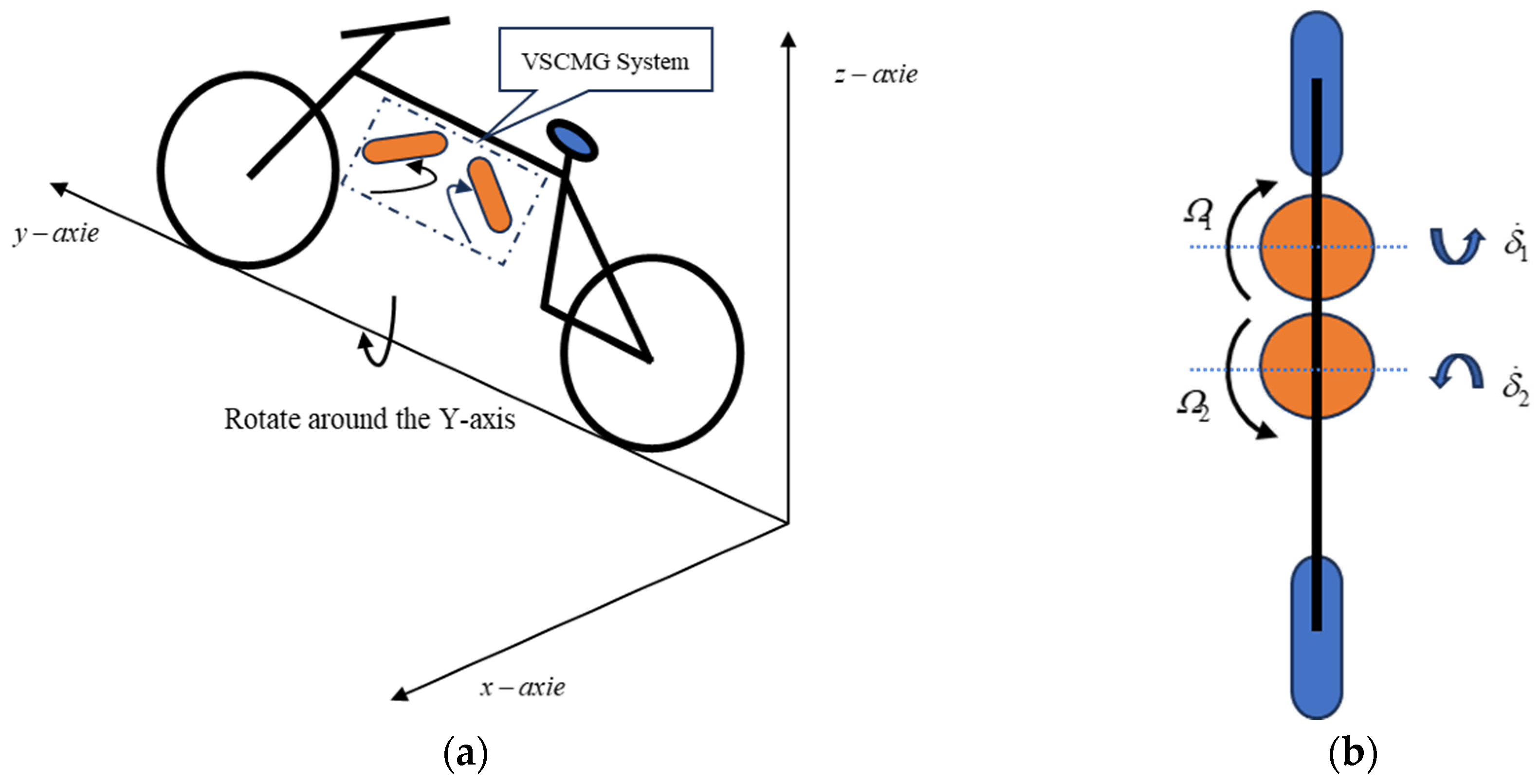
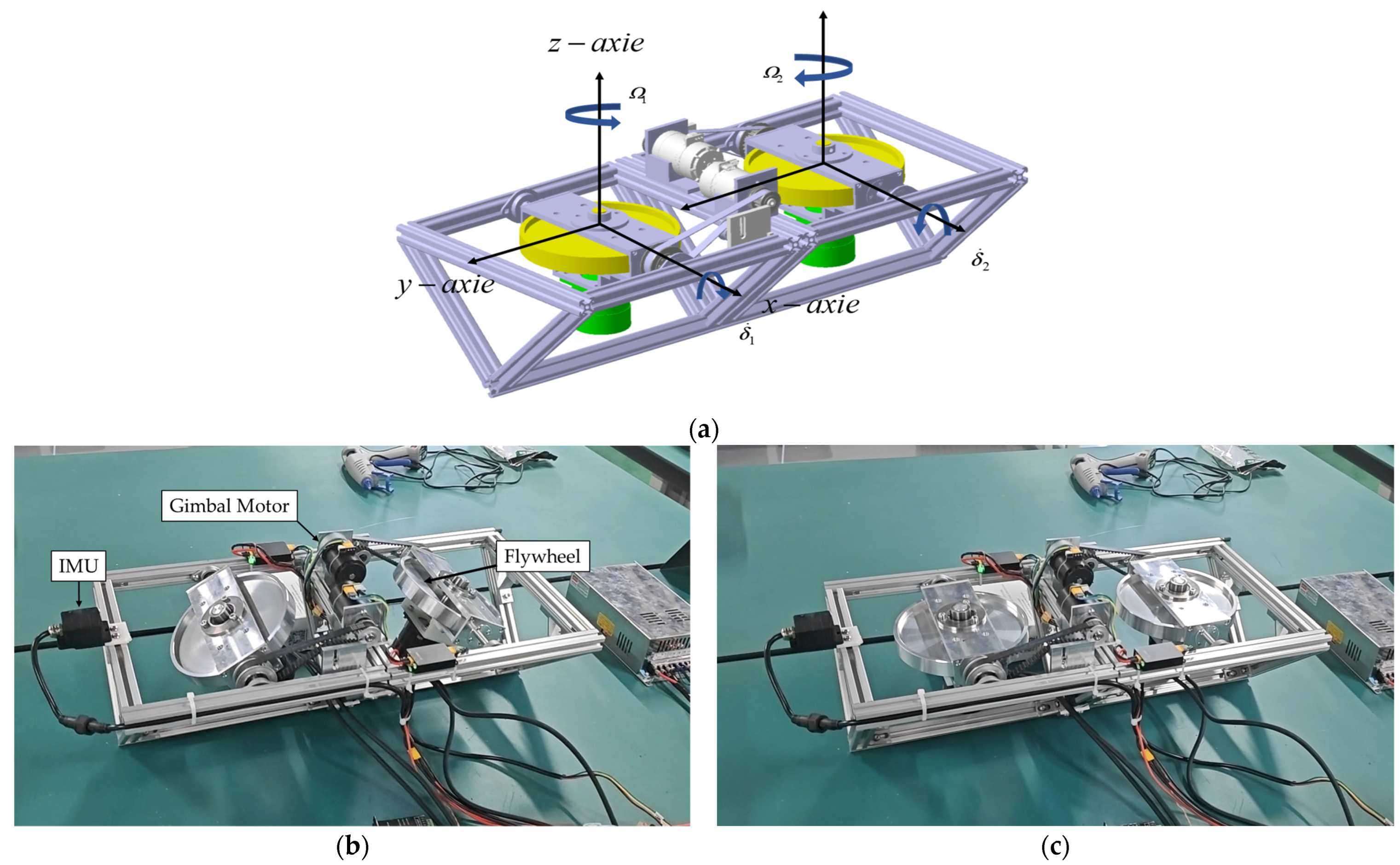
2. Mechanical System

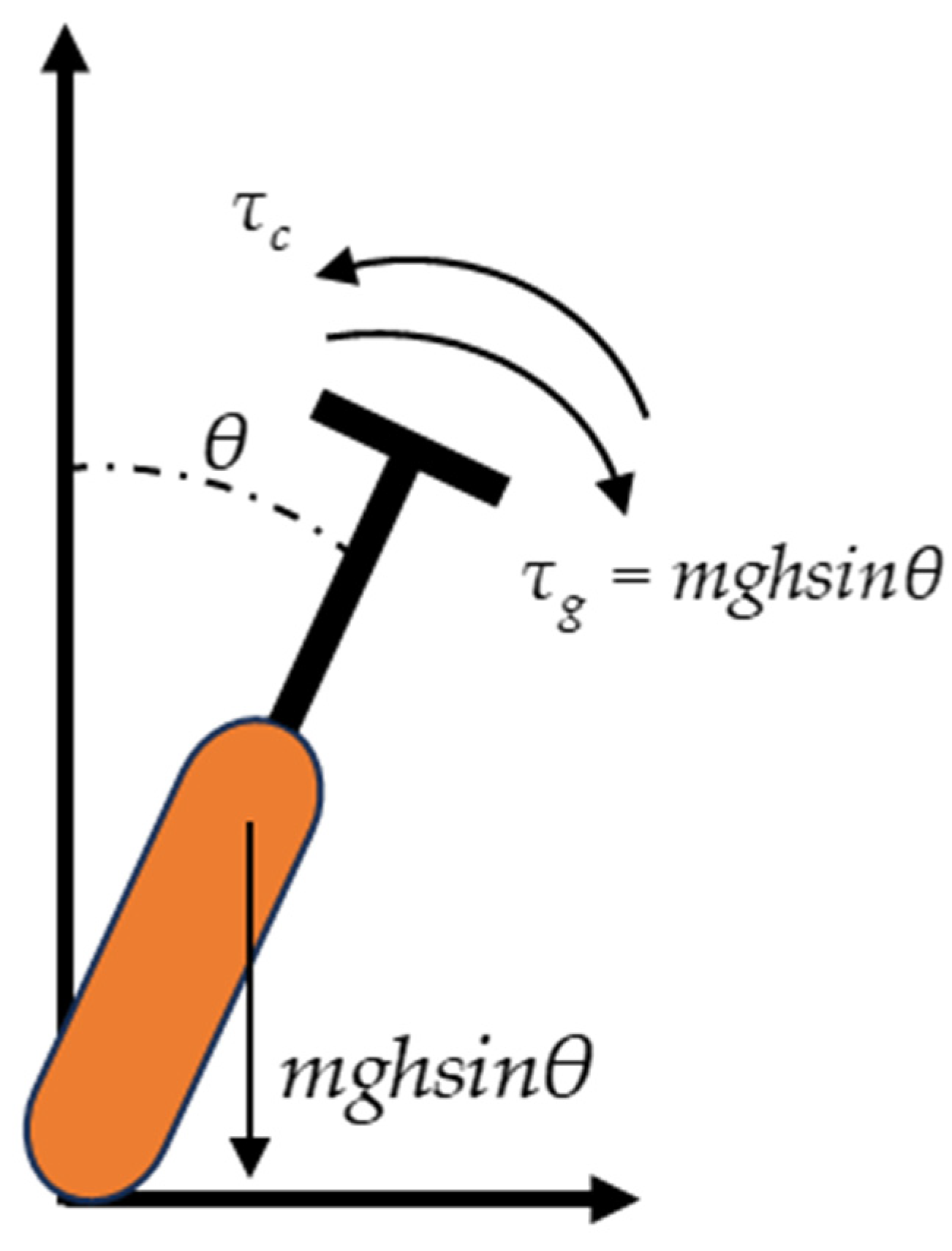
2.1. Dynamics Modeling of the System

The active stability system of a bicycle equipped with a VSCMG is shown in Figure 1. It consists of two CMG flywheels installed side by side under the main beam of a regular bicycle, which have adjustable flywheel speed and adjustable gimbal angular velocity to achieve attitude adjustment and power constraint. The two flywheels are designed to rotate in opposite directions, as illustrated in Figure 1b, to enhance the stability of the output torque; the flywheel speed and gimbal angular velocity are independently controlled by the control law to enable more flexible attitude adjustment.
Several researches [1,26,27] have studied bicycles equipped with CMG systems and demonstrated that they can maintain stability during turning maneuvers. This study primarily investigates the power-constrained control and attitude stabilization of bicycles equipped with VSCMG systems. To simplify the analysis, the system is reduced to a single-axis balancing model, considering only rotational motion about the axis, as shown in Figure 2.
The simplified equations of motion are derived based on the angular momentum theorem, leading to the system’s dynamic equation:
τ c mgh sin θ = I θ ¨
where τ c is the output torque of the VSCMG system, m is the total mass, g is the gravitational acceleration, θ is the body angle in the single-axis balancing model, I is the total moment of inertia of the system, and θ ¨ is the angular acceleration of the system. The net external torque acting on the system induces an angular acceleration about the axis connecting the two wheels, forming a kinematic equation similar to that of a single-axis inverted pendulum.

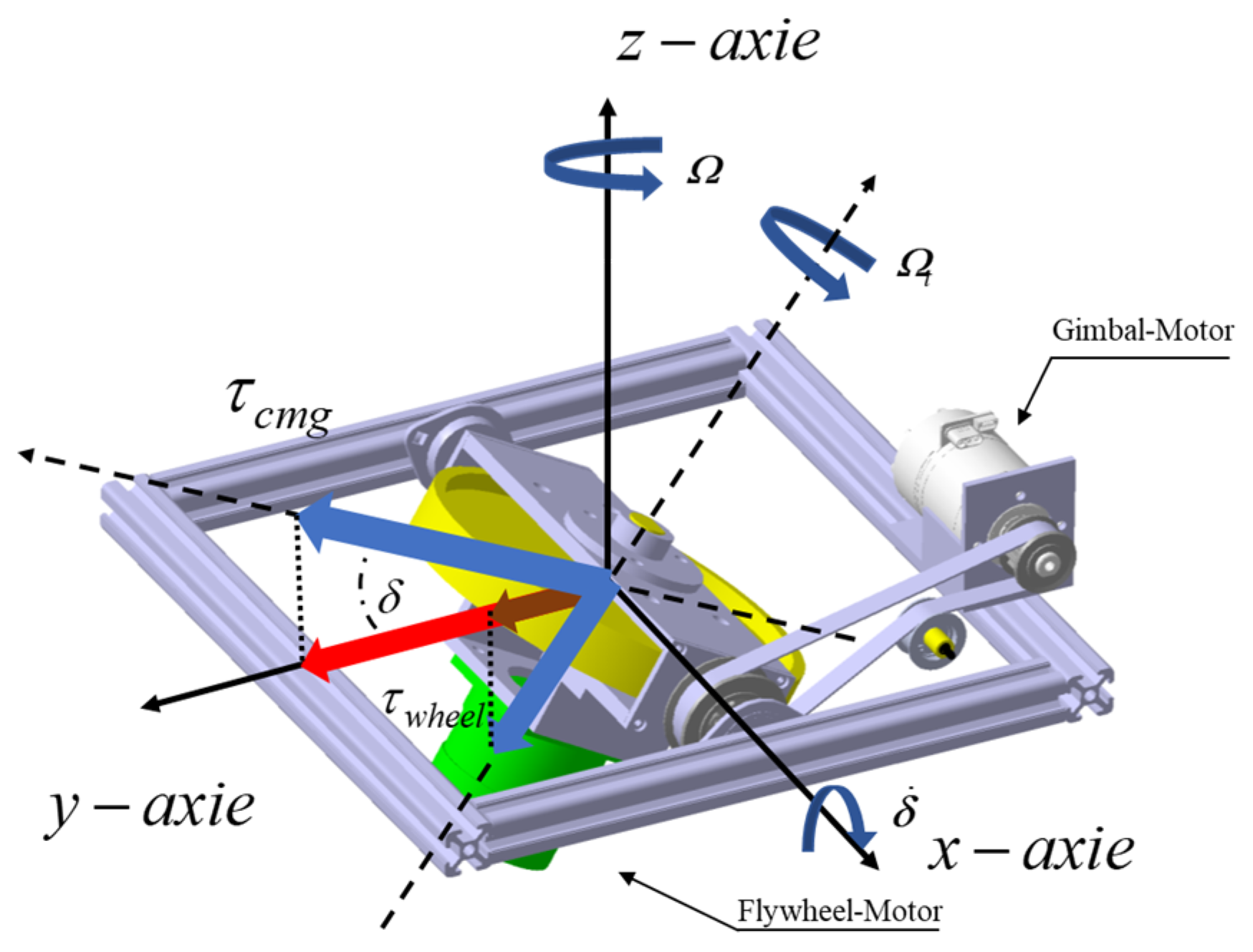
2.2. Torque Output Model of the VSCMG System

The VSCMG system, as illustrated in Figure 3, consists of a high-speed rotating flywheel driven by a flywheel motor and a gimbal structure. The gimbal motor drives the flywheel to rotate about the y-axis, generating control torque in the plane perpendicular to both the flywheel spin axis and the gimbal axis.
Unlike the SGCMG system, the VSCMG system features a variable flywheel speed, which generates an additional torque when the flywheel accelerates or decelerates. In satellite applications, this additional torque enables SGCMG systems to escape singularities through zero-momentum maneuvers. In bicycle systems, however, the interaction between the gimbal motion and flywheel speed variation results in two distinct control torques. The torque generated by the flywheel speed variation may act as a disturbance torque, affecting the stability of the system. To analyze the impact of torque magnitude and direction on the motion of a single-axis balancing bicycle, the following section examines the torque output of the VSCMG system along the Y-axis, as shown in Figure 4.
The angular momentum of the dual parallel single-gimbal VSCMGs in the roll direction is given by:
H = h 1 +   h 2 = J Ω 1 sin δ 1 + J Ω 2 sin δ 2
where Ω i is the rotational speed of the flywheel of the i-th VSCMG and δ i is the gimbal angle of the i-th gyroscope. When both the gimbal angle and the flywheel speed of the VSCMGs are changed simultaneously, both the direction and the magnitude of the flywheel angular momentum change, enabling the system to output both gyroscopic torque and flywheel torque. The torque output equation for the VSCMGs is then:
τ c = H d t = H δ δ ˙ + H Ω Ω ˙
where Ω ˙ = [ Ω ˙ 1   Ω ˙ 2 ] , The variable Ω ˙ i is the first-order derivative of Ω i , representing the acceleration of the flywheel. Let H δ = C , H δ = D ; then, Equation (3) can be rewritten as follows:
τ c = C δ ˙ + D Ω ˙ = Q δ ˙ Ω ˙
where:
C = J [ Ω 1 cos δ 1 Ω 2 cos δ 2 ] D = J [ sin δ 1 sin δ 2 ]
Q = [ C D ] .
In VSCMG systems, there are two modes of torque output: gyroscopic torque and flywheel torque, which can be expressed as follows:
τ i cmg = J Ω i δ ˙ i τ i wheel = J Ω i ˙
The direction is determined by matrices C and D .
From the above derivation, it can be inferred that the two torque outputs of the VSCMG contribute to the active balance assistance of the bicycle in the Y-axis direction.

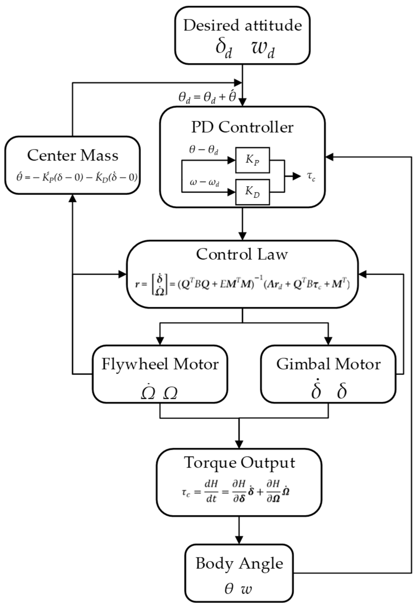
3. Design Controller of Torque

Figure 5 illustrates the closed-loop control process of an integrated single-axis attitude and power control algorithm based on a Variable Speed Control Moment Gyroscope (VSCMG) system. The process initiates with the input of the desired attitude, comprising the target tilt angle and angular velocity, serving as the control objectives to guide the bicycle in achieving single-axis balance. Subsequently, a center-of-mass alignment module dynamically adjusts the center of mass position based on the gimbal angle and gimbal angular velocity, mitigating deviations due to manufacturing or installation inaccuracies and preventing control failures caused by the gimbal angle approaching singularity positions (±90°). The adjusted attitude target, along with the current attitude, is then fed into a PD controller to compute the required control torque for driving attitude adjustments. Following this, the control law module, considering both power constraints and torque demands, calculates the flywheel acceleration and gimbal angular velocity as maneuvering rates, which are distributed to the flywheel motor and gimbal motor. The flywheel motor regulates the flywheel speed according to the assigned flywheel acceleration, generating flywheel torque, while the gimbal motor adjusts the gimbal angle based on the gimbal angular velocity, producing gyroscopic torque. These two torques collectively form the total output torque, which is applied to the bicycle system to adjust its body angle and angular velocity. Meanwhile, the flywheel speed, flywheel acceleration, gimbal angle, and gimbal angular velocity are fed back to the control law module in real time to dynamically refine the maneuvering rates, ensuring control accuracy. Finally, the body angle and angular velocity are continuously monitored via sensors and fed back to the PD controller, establishing a closed-loop control system. This ensures that the system achieves attitude stability under power constraints while optimizing energy consumption and enhancing endurance.

3.1. Torque Output Design by PD Controller

To investigate the system’s controllability, a parallel control moment gyroscope system is employed, where torques in directions other than the Y-axis can be neglected. A proportional–derivative (PD) controller is utilized to compute the total torque demand required for single-axis balance, chosen for its simplicity and effectiveness in stabilizing linear systems. The PD controller is designed as follows:
τ c = K D ω ω d K P θ θ d
In the equation, ω represents the angular velocity of the single-axis balance system, ω d denotes the desired angular velocity, θ indicates the current tilt angle, and θ d signifies the desired tilt angle of the system. The computed torque from Equation (7) serves as the total torque input, which is then allocated to the flywheel speed and gimbal angular velocity through the control law described in Section 3.2, optimizing performance under power, torque, and actuator error constraints.

3.2. Control Law Based on VSCMG Power Constraints

In this section, the maneuver rate allocation strategy for the Variable Speed Control Moment Gyroscope (VSCMG) system is developed, considering the power constraints of the system.
Since the system incorporates two torque output models, the next challenge is to reduce the flywheel speed while ensuring that the combined torque from the two models approaches the torque output of the PD controller, thereby achieving controllable torque output.
Initially, the system is subject to a desired power constraint. Starting from this desired power constraint, the expected acceleration of the flywheel is designed. During the acceleration and deceleration of the flywheel, an error torque arises. By calculating this error torque and subtracting it from the total torque output of the PD controller, the desired torque for gimbal precession is obtained. To address this, an objective function is formulated, which comprehensively accounts for the error between the desired and actual maneuver rates, the error between the desired and actual torques, and the error between the desired and actual power levels. This objective function is then used to compute the output maneuver rate, which is subsequently applied to the actual motor.

3.2.1. Control Law Design for the Desired Flywheel Acceleration

During the operation of the flywheel, the power consumption of the motor is a critical factor in the design and optimization of the Variable Speed Control Moment Gyroscope (VSCMG) system, particularly when reducing the flywheel speed is required to achieve energy management and torque output control. The power consumption of the flywheel directly impacts the system’s energy efficiency and control accuracy. Therefore, establishing a precise power model is essential for designing low-speed operation strategies, minimizing energy losses, and maintaining the stability of torque output. The power during flywheel operation can be expressed as:
P = T Ω ,   T = J Ω ˙
where T represents the torque output of the flywheel, J is the moment of inertia of the flywheel, Ω denotes the angular velocity of the flywheel, and Ω ˙ is the angular acceleration.
Further derivation yields the mechanical power of the motor as:
P = J Ω Ω ˙
Based on the above formulation, the power characteristics of the flywheel during operation can be analyzed. Since the flywheel must overcome its rotational inertia to maintain or adjust its motion, the power P is always non-zero. The magnitude of the power is closely related to the angular velocity Ω and the angular acceleration Ω ˙ . Notably, at high angular velocities Ω , even a small angular acceleration Ω ˙ can result in significant power consumption, leading to increased energy demands. Therefore, reducing the flywheel speed Ω emerges as an effective strategy to lower power consumption. For instance, by decreasing Ω, the power demand can be significantly reduced while maintaining the torque output capability, thereby enhancing the system’s energy efficiency. Additionally, lowering the speed can mitigate heat dissipation and mechanical wear in the motor, further extending the system’s operational lifespan.
Based on the above formula and motor characteristics, it is evident that power is proportional to rotational speed in certain ranges. In other words, as the rotational speed increases, the power also increases correspondingly; conversely, when the rotational speed decreases, the power decreases accordingly.
Since the system employs single-axis attitude control, the torques from the two VSCMG systems are superimposed. Consequently, the two flywheel motors are symmetrically controlled with identical speeds. Given a desired power constraint factor P w , Equation (9) can be rewritten as:
P w = J Ω Ω ˙ d 2
where Ω d represents the desired acceleration of the flywheel; Equation (10) can be rewritten as:
Ω ˙ d = 2 P w ( J Ω ) 1
The relationship between power limitation and the desired flywheel acceleration is derived through the above formula, laying the groundwork for the design of the subsequent gimbal angular velocity control law.

3.2.2. Design of the Control Law for Gimbal Angular Velocity

To reduce energy consumption by lowering motor speed, the torque provided by the flywheel during acceleration or deceleration is relatively small, and the attitude control torque is primarily supplied by adjusting the gimbal’s angular velocity. However, changing the flywheel speed introduces torque deviations, which must be compensated by the CMG system to prevent deviations in the system’s total output torque due to the reduced speed. Therefore, by substituting Equation (11) into Equation (4), the gimbal angular velocity control law is derived as shown in Equation (12).
δ ˙ d = C 1 ( τ c D Ω ˙ d )
where δ ˙ d represents the desired gimbal angular velocity, serving as the primary source of torque for system balance.

3.2.3. Real-Time Allocation of Control Law

To ensure that the control law outcomes of the newly designed real-time sampling control law align with the desired flywheel acceleration and gimbal angular velocity design results, the control law design must satisfy the following performance index function:
L = min u 1 2 ( r e T A r e + τ e T B τ e + P e E P e )
The performance index function L is minimized over the control input u, which represents the flywheel angular accelerations Ω ˙ and gimbal angular velocities δ ˙ to be optimized. The torque deviation is defined as r e = r r d , r = [ δ ˙   Ω ˙ ] , r d = [ δ ˙ d   Ω ˙ d ] , A   = I 4 × 4 , τ e = Q × r τ c , representing the torque deviation output by the VSCMG system. Additionally, P e = P     P w denotes the power tracking deviation of the VSCMG cluster, where P is the sum of the real-time power of the two flywheels. The parameter B is a user-defined weighting factor that adjusts the emphasis on minimizing the torque deviation, while E is another user-defined weighting factor that adjusts the emphasis on minimizing the power tracking error. Larger values of B and E correspond to smaller desired torque and power tracking errors, respectively.
Expanding Equation (13) yields:
L = 1 2 ( r r d ) T A ( r r d )   + 1 2 ( Q · r τ c ) T B ( Q · r τ c )   + 1 2 ( M · r P w ) T E ( M · r P w ) T
Differentiating Equation (13) and setting it equal to zero yields:
L r = A ( r r d ) + Q T B ( Q · r τ c ) + M E ( M · r P w ) = 0
where M   = [ 0   0   J Ω 1   J Ω 2 ] . Under the condition that the first-order derivative of the performance index function L equals zero, the tracking control law that minimizes both the flywheel torque demand and power demand can be obtained as:
r = δ ˙ Ω ˙ = ( Q T B Q + E M T M ) 1 ( A r d + Q T B τ c + M T )
When B and E are greater than zero, the second-order derivative of L is positive, and when the first-order derivative of L equals zero, L reaches its minimum value. As r e approaches the 4 × 1 zero vector, δ ˙ tends toward δ ˙ d , and Ω ˙ approaches Ω ˙ d . When B and E are positive, the newly designed control law ensures that the control law outcomes converge to the desired flywheel acceleration and gimbal angular velocity design results. Thus, the proposed control methodology achieves integrated single-axis attitude and power control, ensuring both stability and energy efficiency under power constraints.

3.2.4. Center of Mass Alignment and Singularity Avoidance

Owing to manufacturing and installation inaccuracies, the system’s center of mass cannot be precisely aligned with the Y-Z plane of the bicycle, resulting in an inevitable rolling torque about the Y-axis. To counteract this torque, the system primarily responds by adjusting the gimbal angle, generating gimbal angular velocity that produces a counteracting torque to balance the gravitational torque. However, the continuous rotation of the gimbal angle may lead to a singular position (±90°), where the matrix C reverses, causing control failure. Consequently, a center of mass alignment algorithm is developed based on the characteristics of the gimbal angle and angular velocity to achieve center of mass alignment and singularity avoidance.
Currently, based on the gimbal angle and angular velocity, a PD controller or an offset angle is utilized. By dynamically adjusting the offset angle to balance the center of mass position, the gimbal angular velocity is reduced to zero. The offset angle is expressed as shown in Equation (17):
θ   ´ = K P ´ ( δ 0 ) K ´ D ( δ ˙ 0 )
Therefore, the desired target angle for bicycle balance is:
θ d =   θ d + θ ´
Equations (17) and (18) employ an independent PD controller to compensate for gimbal angle deviations caused by center-of-mass misalignment. Without compensation, such misalignment induces a persistent gravitational torque, leading to a non-zero gimbal angular velocity that could drive the angle beyond ±90°, resulting in singularity. By applying Equations (17) and (18), the desired body angle is adjusted to counteract the gravitational torque due to center-of-mass offset, ultimately reducing the gimbal angle to near zero and preventing singularity issues.
Through the center-of-mass alignment and singularity avoidance algorithm, we prevent the gimbal angle from continuously rotating and encountering singularity issues, while enabling the gimbal angle to return to near zero. This provides sufficient rotational margin to handle sudden external force disturbances.
At this point, we have completed the control methodology section for the integrated single-axis attitude and power control.

4. Experiment and Validation

4.1. Experimental Environment Setup

A bicycle-like platform was developed to simulate rolling motion about the Y-axis, facilitating the validation of the attitude balancing and power constraint algorithms. The system incorporates two parallel-installed VSCMG units, namely by connecting the VSCMG systems depicted in Figure 4 in parallel, with the addition of a bottom support frame to provide stability. The main control system employs a microcontroller equipped with an STM32F4 chip, which acquires feedback signals from the flywheel motor and gimbal angle motor via the CAN bus, collecting real-time data on flywheel speed Ω , gimbal angle δ , and gimbal angular velocity δ ˙ . Additionally, attitude angle θ and attitude angular velocity θ ˙ are obtained from an IMU measurement device through the CAN bus; sensor data are fused using algorithms such as Kalman filtering and low-pass filtering to eliminate high-frequency noise, thereby enhancing sensor accuracy. Furthermore, a power meter with RS485 communication functionality is connected in series with the main power supply to measure power consumption during speed reduction, verifying compliance with power constraint objectives. The flywheel speed and gimbal angular velocity of each unit are independently controlled using the control law given by Equation (16), Figure 6 includes illustrations of the motion states of the system components, the initial adjustment phase (θ: 15.5° → ≈ 0°), and the stable equilibrium (θ ≈ 0°).
Table 1 below presents the experimental values of physical parameters referenced in the equations above, determined through experimental measurements to reflect the system’s characteristics and control performance.
The flywheel motor employs a brushless DC motor with Hall sensors, enabling real-time monitoring of rotor speed. The gimbal motor utilizes a planetary gear servo motor equipped with Field-Oriented Control (FOC). The parameters are shown in Table 2 and Table 3:

4.2. Experimental Conditions and Phenomena

We prepared the following three experimental conditions to validate the effectiveness of the Integrated Power and Attitude Control (IPAC) task through observed phenomena. To ensure the system has sufficient angular momentum to jump and stand upright without external assistance, and to prevent the loss of angular momentum reserve due to excessively low rotation speed, we set the initial flywheel rotation speed to 4000 RPM, with a maximum rotation speed of 4000 RPM and a minimum rotation speed of 1500 RPM.
  • Comparison of SGCMG and VSCMG Systems;
  • Different power factors P w ;
  • Performance under external force disturbance

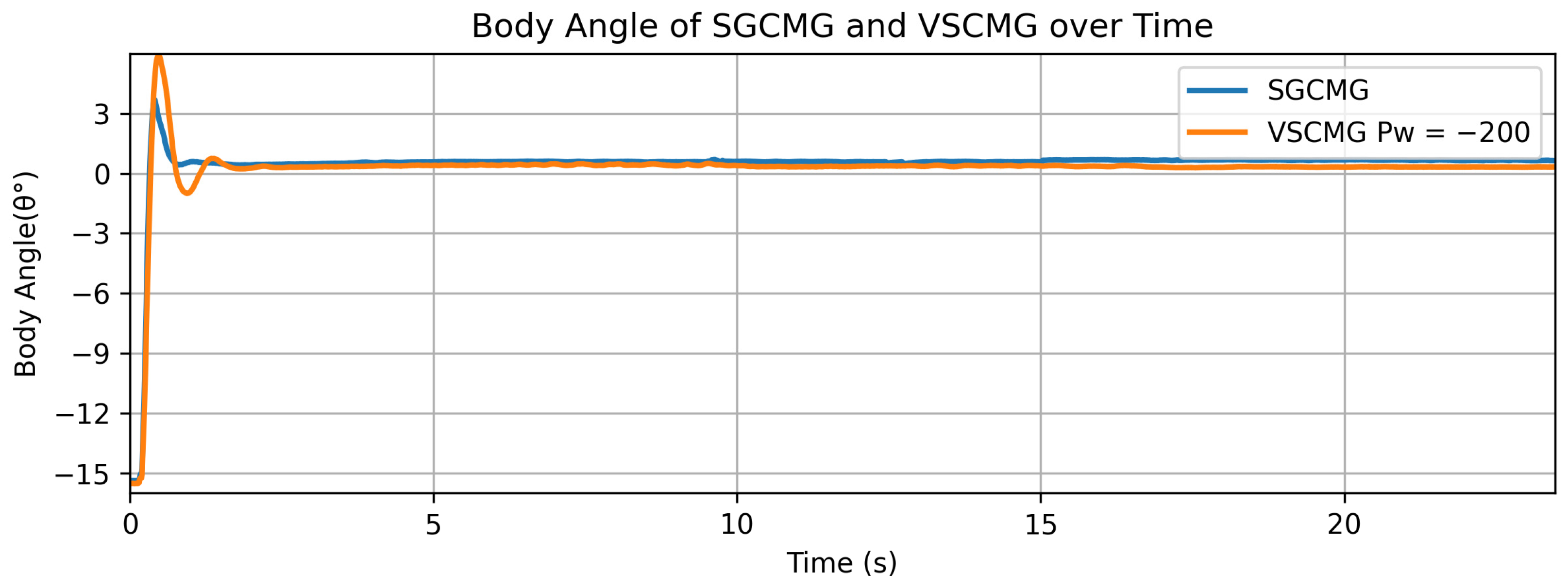
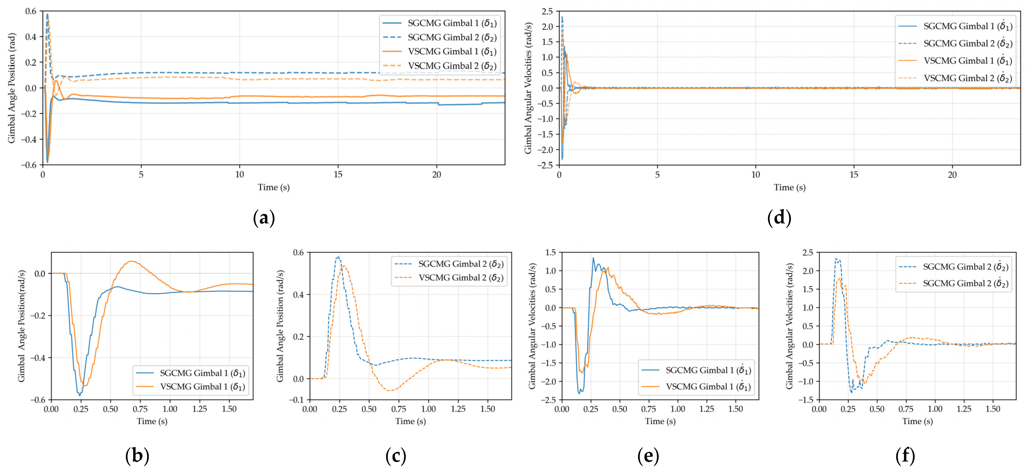
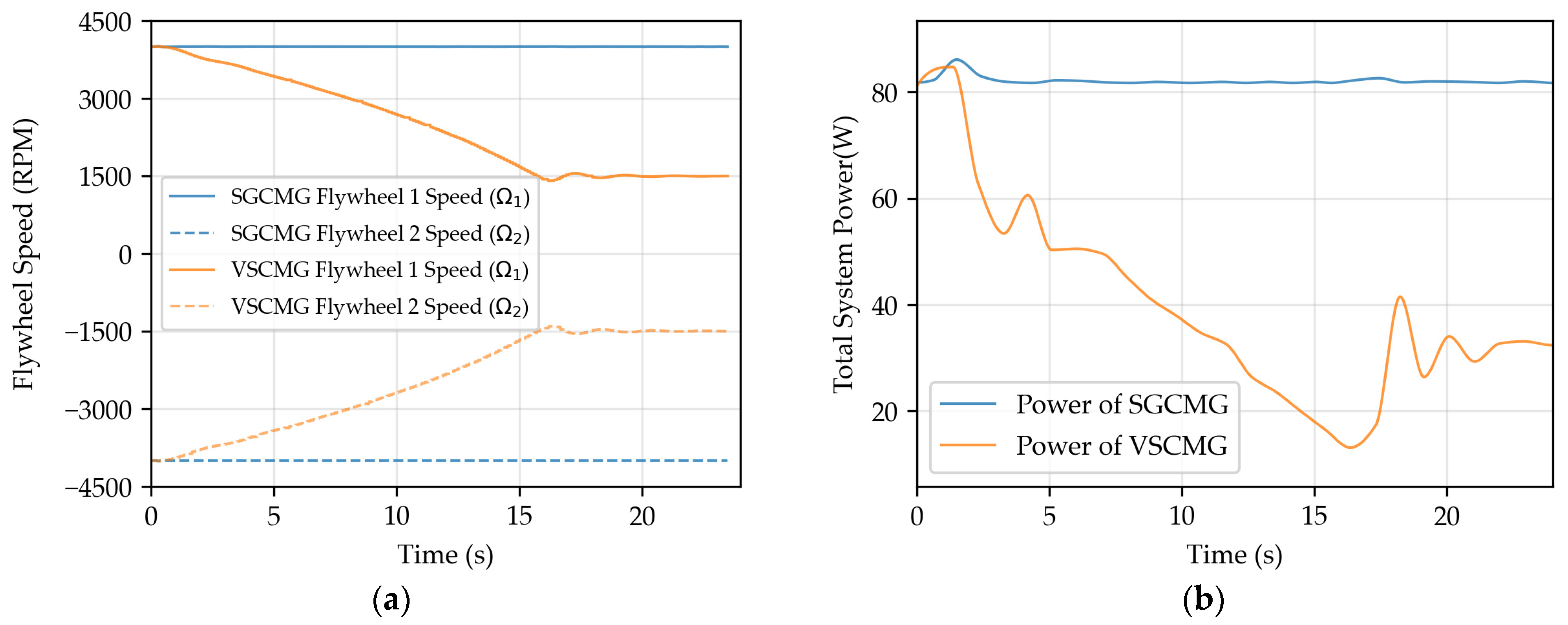
4.2.1. Comparison of SGCMG and VSCMG Systems

Through the SGCMG system and VSCMG system setup, with an initial rotation speed of 4000 RPM, the system achieves a balanced state. The body attitude angle of the setup, the gimbal angle of the CMG system, the gimbal angular velocity, the flywheel rotation speed, and the total power are shown in the figure:
As shown in Figure 7, the bicycle balance system using the VSCMG system can, like the SGCMG system, achieve upright posture from approximately 15.5° within a few seconds and maintain balance stability near 0°, demonstrating robust stability. The phenomenon that the angle after balancing is not exactly 0° also validates the Center of Mass Alignment and Singularity Avoidance discussed in Section 3.2.4.
From Equations (5) and (11), it can be derived that the variation of the gimbal angle position δ is a crucial input parameter of the system, affecting the system output: the gimbal angular velocity δ ˙ , which in turn influences the torque output applied to attitude adjustment. The variations of the gimbal angle position and gimbal angular velocity for the SGCMG and VSCMG systems are shown in Figure 8:
The flywheel speed of the device using the VSCMG system is variable, and changes in rotational speed lead to variations in power. By setting a power constraint coefficient, the system’s rotational speed is reduced while maintaining its attitude stability. The actual power is measured using a power sensor, as shown in Figure 9:
The results of Section 4.2.1 demonstrate that the bicycle employing the VSCMG system can achieve attitude adjustment and maintain stability in nearly the same duration as the SGCMG system. Additionally, when reducing the flywheel speed, the system can compensate for the resulting disturbance torque by adjusting the gimbal angular velocity. Compared to the SGCMG system, the overall power consumption of the system is significantly reduced. This indicates that the VSCMG system can provide sufficient angular momentum at high speeds during the bicycle’s upright phase while lowering the speed during balance maintenance to reduce electrical energy consumption, thereby making long-endurance operation feasible.

4.2.2. Performance Under External Force Disturbance

We also investigated the effects of different power constraint factors on flywheel speed and power, using P w values of −300, −200, and −100. The variations in flywheel speed and power over time are illustrated in Figure 10 and Figure 11.
Experimental observations indicate that different power constraint factors lead to variations in the acceleration of the flywheel speed, resulting in differing rates of speed reduction. A larger power constraint factor causes the flywheel speed to decrease more rapidly, accompanied by a faster reduction in the overall system power. When the speed drops to the constrained limit, the power initially rises significantly for a period before decreasing and stabilizing. This phenomenon occurs because the motor accelerates to maintain the speed after reaching the speed limit. Ultimately, the power levels under the three different constraint factors converge to similar values, suggesting that the power constraint factor primarily affects the rate of power reduction. In practical engineering applications, selecting an appropriate coefficient may provide protection for certain electronic components, preventing rapid current changes—caused by positive power constraint factors that accelerate the flywheel—from adversely affecting the lifespan of these components.

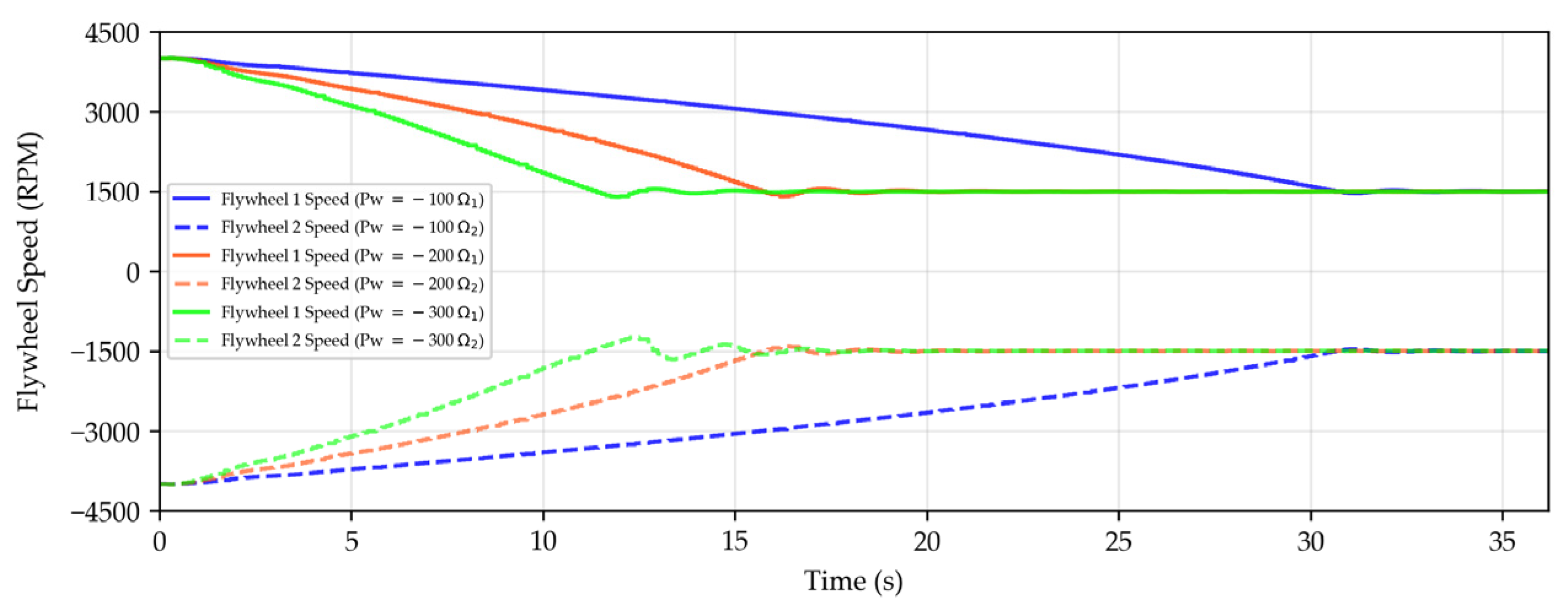
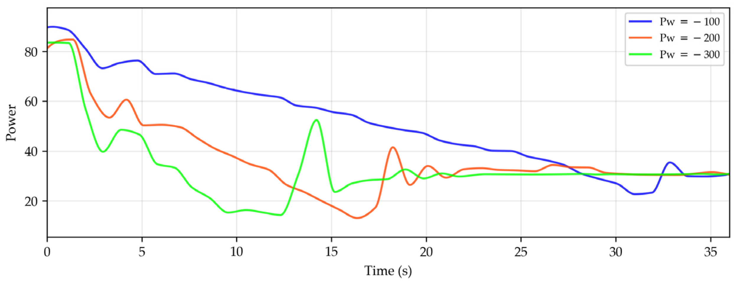
4.2.3. Different Power Factors P w

When the flywheel speed changes, its corresponding angular momentum also varies. A decrease in flywheel speed results in a reduction of the stored angular momentum, thereby weakening the system’s disturbance rejection capability. The performance after attaching a 10 N counterweight to the right side of the gimbal, with flywheel speeds of 4000 RPM and 1500 RPM, is shown in Figure 12, Figure 13 and Figure 14:
From Figure 12, Figure 13 and Figure 14, it is evident that as the rotational speed decreases, the system’s disturbance rejection capability notably weakens. Although the system can maintain balance, the body angle exhibits noticeable oscillations, and the torque output parameter, namely the gimbal angular velocity, also shows significant oscillations. Additionally, the gimbal angle position undergoes considerable changes. However, for a bicycle employing the VSCMG system, using a positive power constraint factor ( P w ) can increase the flywheel speed, thereby enhancing its disturbance rejection capability. Therefore, in subsequent studies, the power constraint factor ( P w ) should be designed as an adaptive factor, capable of both adaptive power reduction and adaptive disturbance rejection.

5. Conclusions

This study presents a novel bicycle balancing system integrating a Variable Speed Control Moment Gyroscope (VSCMG) to achieve simultaneous attitude stabilization and power-constrained control, addressing the trade-off between stability and energy efficiency in autonomous bicycles. The proposed system leverages the variable-speed capability of VSCMG to dynamically adjust flywheel speeds, ensuring effective torque allocation while minimizing power consumption. A comprehensive gimbal-based control framework was developed, incorporating a proportional-derivative (PD) controller for torque computation, a least-squares-based steering law for real-time flywheel speed and gimbal angular velocity optimization, and a center-of-mass alignment algorithm to mitigate singularities and enhance robustness. Experimental validation was conducted on a bicycle-like platform equipped with two parallel VSCMG units, demonstrating the system’s ability to achieve autonomous upright posture and maintain balance under various conditions.
The experimental results highlight several key findings. First, the VSCMG system successfully stabilized the bicycle from an initial tilt angle of approximately 15.5° to near 0° within a short duration, exhibiting stability comparable to traditional Single Gimbal Control Moment Gyroscope (SGCMG) systems. However, unlike SGCMG systems, which maintain constant high flywheel speeds, the VSCMG system reduced its flywheel speed from 4000 RPM to 1500 RPM during steady-state operation, achieving a significant reduction in power consumption. In this experiment, the VSCMG system achieved an approximately 60% reduction in total power consumption compared to the SGCMG system, with no significant difference in stability. The system successfully adjusted its posture from an initial tilt angle to near 0° within a short duration and maintained stability near 0° even as flywheel speed decreased, highlighting the effectiveness of the power-constrained control strategy in improving energy efficiency. Second, the system’s response to external disturbances was thoroughly evaluated by applying a 10 N counterweight to the gimbal’s right side at flywheel speeds of 4000 RPM and 1500 RPM. At the higher speed, the system exhibited robust disturbance rejection with minimal oscillations in body angle, gimbal angle position, and angular velocity. In contrast, at the lower speed, while balance was maintained, noticeable oscillations in these parameters indicated a reduced disturbance rejection capability due to diminished angular momentum, underscoring the need for adaptive speed adjustments. Third, the influence of different power constraint factors was investigated, revealing that larger factors accelerate flywheel speed reduction, leading to faster power decreases, though all tested factors eventually stabilized at similar power levels. This suggests that the power constraint factor can be tuned to balance energy efficiency and component longevity in practical applications.
Despite these advancements, several limitations warrant further investigation. The reduction in flywheel speed, while beneficial for energy conservation, compromises the system’s angular momentum reserve, weakening its ability to counter sudden external disturbances, as evidenced by increased oscillations at lower speeds. Future research will focus on developing adaptive control strategies that dynamically increase flywheel speed in response to abrupt external forces, thereby enhancing disturbance rejection without sacrificing energy efficiency. In the case of full-sized bicycles or electric vehicles, we will increase the flywheel’s moment of inertia and maximum rotational speed to ensure it can rapidly stabilize and maintain equilibrium on heavier platforms. Additionally, the system’s performance under complex conditions, such as rugged terrain or high-speed maneuvers, remains unexplored. Subsequent studies will aim to incorporate adaptive flywheel speed regulation and advanced terrain-adaptive control algorithms to improve robustness and versatility, paving the way for practical deployment in long-endurance autonomous bicycles.

Author Contributions

Conceptualization, project administration H.K.; methodology, writing—original draft, formal analysis preparation visualization X.C.; software Z.W.; investigation J.Z.; funding acquisition, writing review and Editing G.X. All authors have read and agreed to the published version of the manuscript.

Funding

This research was funded by National Natural Science Foundation of China, grant number 12211530449 and the S & T Program of Hebei (246Z2301G).

Data Availability Statement

The data is included in the article.

Conflicts of Interest

The authors declare that they have no known competing financial interests or personal relationships that could have appeared to influence the work reported in this paper.

References

  1. Hartz, F.; Zehnder, P.; Resch, T.; Römmermann, G.; Hartmann, V.; Schwarz, M.; Kirchhoff, C.; Biberthaler, P.; Zyskowski, M. Characteristics of e-scooter and bicycle injuries at a university hospital in a large German city—A one-year analysis. Inj. Epidemiol. 2025, 12, 2. [Google Scholar] [CrossRef] [PubMed]
  2. Chen, B.; Fei, X.; Fan, Y.; Dan, Y.; Huang, Z. Frame Angular Velocity Control Design of SGCMG for Unmanned Two-Wheeled Motorcycle. Machines 2023, 11, 371. [Google Scholar] [CrossRef]
  3. Yetkin, H.; Kalouche, S.; Vernier, M.; Colvin, G.; Redmill, K.; Ozguner, U. Gyroscopic stabilization of an unmanned bicycle. In Proceedings of the 2014 American Control Conference, Portland, OR, USA, 4–6 June 2014; pp. 4549–4554. [Google Scholar] [CrossRef]
  4. Hou, Z.; Geng, Y.; Wu, B.; Huang, S. Spacecraft angular velocity trajectory planning for SGCMG singularity avoidance. Acta Astronaut. 2018, 151, 284–295. [Google Scholar] [CrossRef]
  5. Wang, L.; Guo, Y.; Wu, L.; Chen, Q. Improved optimal steering law for SGCMG and adaptive attitude control of flexible spacecraft. J. Syst. Eng. Electron. 2015, 26, 1268–1276. [Google Scholar] [CrossRef]
  6. Chen, C.; Liu, X.; Cong, B.; Jin, Y. Dynamical sliding mode control of spacecraft attitude using SGCMG systems. In Proceedings of the 29th Chinese Control Conference, Beijing, China, 29–31 July 2010; pp. 2240–2244. [Google Scholar]
  7. Wardle, D.; Gregory, T.; Cazzolato, B. Electronic training wheels: An automated cycling track stand. In Proceedings of the Australasian Conference on Robotics and Automation, The University of Melbourne, Melbourne, Australia, 2–4 December 2014. [Google Scholar]
  8. Chen, C.-K.; Chu, T.-D.; Zhang, X.-D. Modeling and Control of an Active Stabilizing Assistant System for a Bicycle. Sensors 2019, 19, 248. [Google Scholar] [CrossRef] [PubMed]
  9. Uematsu, E.; Ueno, S.; Higuchi, T. Sub-Optimal Control Law for Minimum Energy Attitude Maneuver using CMGs. Trans. Jpn. Soc. Aeronaut. Space Sci. Aerosp. Technol. Jpn. 2014, 12, Pd_19–Pd_25. [Google Scholar] [CrossRef] [PubMed]
  10. Meijaard, J.; Papadopoulos, J.M.; Ruina, A.; Schwab, A. Linearized dynamics equations for the balance and steer of a bicycle: A benchmark and review. Proc. R. Soc. A Math. Phys. Eng. Sci. 2007, 463, 1955–1982. [Google Scholar] [CrossRef]
  11. Guan, R.; Li, C.; Lv, Q. VSCMG System Model Based on Euler Kinematics Equation. In Innovative Computing: Proceedings of the 4th International Conference on Innovative Computing (IC 2021); Springer: Singapore, 2022; pp. 409–416. [Google Scholar] [CrossRef]
  12. Prabhakaran, V.S.; Sanyal, A.K.; Leve, F.; McClamroch, N.H. Geometric Mechanics Based Modeling of the Attitude Dynamics and Control of Spacecraft with Variable Speed Control Moment Gyroscopes. In Proceedings of the ASME 2013 Dynamic Systems and Control Conference, Palo Alto, CA, USA, 21–23 October 2013; Volume 56123. [Google Scholar] [CrossRef]
  13. Biggs, J.D.; Brisotto, S. Robust spacecraft rendezvous using a variable speed control moment gyro and thruster. Aerosp. Sci. Technol. 2021, 112, 106644. [Google Scholar] [CrossRef]
  14. Guo, J.; Chen, X.; Zhu, M.; Zhou, Q. Integrated Control of Attitude Maneuver and Vibration Suppression Using Pyramid-Type SGCMGs. IEEE Trans. Aerosp. Electron. Syst. 2022, 58, 17–26. [Google Scholar] [CrossRef]
  15. Meng, Q.; Yang, H.; Jiang, B. Attitude control reconfigurability analysis of 4-CMGs pyramid configuration spacecraft. In Proceedings of the 2019 12th Asian Control Conference (ASCC), Kitakyushu, Japan, 9–12 June 2019; pp. 1478–1482. [Google Scholar]
  16. Liu, F.; Lyu, K. The Singularity Avoidance Analysis and Designed Steering Law for VSCMG. In Proceedings of the 2022 41st Chinese Control Conference (CCC), Hefei, China, 25–27 July 2022; pp. 2791–2796. [Google Scholar] [CrossRef]
  17. Schaub, H.; Junkins, J. CMG singularity avoidance using VSCMG null motion. In Proceedings of the AIAA/AAS Astrodynamics Specialist Conference and Exhibit, Boston, MA, USA, 10–12 August 1998. [Google Scholar] [CrossRef]
  18. Cheng, Z.; Qin, D.; Wang, D.; Zhang, Z.; Peng, R. Reconfigurability Evaluation of VSCMG Based on Power Consumption Constraint. In Proceedings of the 2023 China Automation Congress (CAC), Chongqing, China, 17–19 November 2023; IEEE: Piscataway, NJ, USA, 2023; pp. 9085–9090. [Google Scholar] [CrossRef]
  19. Fausz, J.; Richie, D. Flywheel simultaneous attitude control and energy storage using a VSCMG configuration. In Proceedings of the IEEE International Conference on Control Applications. Conference Proceedings (Cat. No. 00CH37162), Anchorage, AK, USA, 27 September 2000; IEEE: Piscataway, NJ, USA, 2000. [Google Scholar] [CrossRef]
  20. Richie, D.J.; Lappas, V.J.; Asghar, S. Constrained singularity avoidance using VSCMGs for combined attitude and power tracking. In Proceedings of the 2007 European Control Conference (ECC), Kos, Greece, 2–5 July 2007; IEEE: Piscataway, NJ, USA, 2007. [Google Scholar] [CrossRef]
  21. Altay, A.; Ozan, T. Spacecraft energy storage and attitude control. In Proceedings of the 2nd International Conference on Recent Advances in Space Technologies, 2005. RAST 2005, Istanbul, Turkey, 9–11 June 2005; IEEE: Piscataway, NJ, USA, 2005. [Google Scholar]
  22. Xie, R.Q.; Yao, Y.; He, F.H.; Ma, K.M. Simultaneous attitude stabilization and power tracking for a spacecraft with two VSCMGs. In Proceedings of the 2008 IEEE International Conference on Control Applications, San Antonio, TX, USA, 3–5 September 2008; IEEE: Piscataway, NJ, USA, 2008. [Google Scholar]
  23. Yoon, H.; Panagiotis, T. Spacecraft adaptive attitude and power tracking with variable speed control moment gyroscopes. J. Guid. Control Dyn. 2002, 25, 1081–1090. [Google Scholar] [CrossRef]
  24. Yoshihara, H.; Takahashi, M.; Noumi, A.; Kanzawa, T.; Haruki, M.; Gui, H.; Vukovich, G.; Xu, S.; Wu, Y.-H.; Han, F.; et al. Optimal power management considering attitude control and battery deterioration control for spacecraft with VSCMG/IPACS. In Proceedings of the AIAA SciTech 2020 Forum, Orlando, FL, USA, 6–10 January 2020. [Google Scholar] [CrossRef]
  25. Liu, F.; Gao, F.; Zhang, W.; Zhang, B.; He, J. The optimization design with minimum power for variable speed control moment gyroscopes with integrated power and attitude control. Aerosp. Sci. Technol. 2019, 88, 287–297. [Google Scholar] [CrossRef]
  26. Badgujar, C.; Mohite, S. Design, analysis and implementation of control moment gyroscope (CMG) mechanism to self-balance a moped bike. Mater. Today Proc. 2022, 72, 1517–1523. [Google Scholar] [CrossRef]
  27. El-Aal, A.A.; Roustom, M.; Hegaze, M.M.; Ibrahim, M. Modeling and control of unstable mechanical systems using control moment gyro (CMG). IOP Conf. Ser. Mater. Sci. Eng. 2019, 610, 012053. [Google Scholar] [CrossRef]
Figure 1. (a) Isometric side view of a bicycle equipped with VSCMG in the XYZ axies; (b) Top view of a bicycle equipped with VSCMG.
Machines 13 00459 g001
Figure 2. Torque analysis diagram of a bicycle rotating around its axis.
Machines 13 00459 g002
Figure 3. VSCMG structures, where “ C constant ” indicates a constant rotational speed of the flywheel.
Machines 13 00459 g003
Figure 4. VSCMG torque output. Red and brown arrows indicate the torque components acting about the Y-axis.
Machines 13 00459 g004
Figure 5. Flowchart of VSCMG integrated power attitude control.
Machines 13 00459 g005
Figure 6. (a) Motion states of the system components; (b) Photograph of the system during the initial adjustment phase (θ: 15.5° → ≈ 0°); (c) Photograph of the system at stable equilibrium (θ ≈ 0°).
Machines 13 00459 g006
Figure 7. Variation of the body angle with time for systems using SGCMG and VSCMG (Pw = −200).
Machines 13 00459 g007
Figure 8. (a) Variation in the angular position of the two gimbals in SGCMG and VSCMG systems; (b) Angular position of Gimbal 1 in SGCMG and VSCMG systems (0 to 1.7 s); (c) Angular position of Gimbal 2 in SGCMG and VSCMG systems (0 to 1.7 s); (d) Variation in angular velocities of the two gimbals in SGCMG and VSCMG systems; (e) Angular velocity of Gimbal 1 in SGCMG and VSCMG systems (0 to 1.7 s); (f) Angular velocity of Gimbal 2 in SGCMG and VSCMG systems (0 to 1.7 s).
Machines 13 00459 g008
Figure 9. (a) Variation in the rotational speed of the two flywheels in SGCMG and VSCMG systems; (b) Variation in the power of SGCMG and VSCMG systems.
Machines 13 00459 g009
Figure 10. Flywheel speed variation with time under different power constraint values (Pw = −100, −200, −300).
Machines 13 00459 g010
Figure 11. Power consumption variation with time under different power constraint values (Pw = −100, −200, −300).
Machines 13 00459 g011
Figure 12. Variation of Body angle with time under external force disturbance at 4000 RPM and 1500 RPM.
Machines 13 00459 g012
Figure 13. Variation of Gimbal Angle Position with time under external force disturbance at 4000 RPM and 1500 RPM.
Machines 13 00459 g013
Figure 14. Variation of Gimbal angle velocity with time under external force disturbance at 4000 RPM and 1500 RPM.
Machines 13 00459 g014
Table 1. Experimental Values of Parameters from VSCMG System Equations.
ParametersValueDescription
I0.5 kg · m 2 System’s moment of inertia
J 0.01   kg · m 2 Flywheel’s moment of inertia
h0.25 mSystem center of mass height
K P 3 Attitude controller proportional gain
K D 0.4Attitude controller derivative gain
K P ´ 0.2Offset angle controller proportional gain
K D ´ 0.01Offset angle controller derivative gain
Total Reduction Ratio25.32Servo motor and belt
Table 2. Parameters of flywheel motor.
ModelRated VoltageRated SpeedRated PowerRated CurrentPole Number
AK57BL55-230-06024 V4000 RPM60 W4 A4
Table 3. Parameters of gimbal motor.
ModelRated VoltageRated SpeedReduction RatioRated CurrentPole Number
DM351924 V395 RPM1:19.29.2 A14
Disclaimer/Publisher’s Note: The statements, opinions and data contained in all publications are solely those of the individual author(s) and contributor(s) and not of MDPI and/or the editor(s). MDPI and/or the editor(s) disclaim responsibility for any injury to people or property resulting from any ideas, methods, instructions or products referred to in the content.

