

Design and Optimization of a Piezoelectric Stick-Slip Actuator with Distributed Compliance


Abstract
1. Introduction
2. Conceptual Design
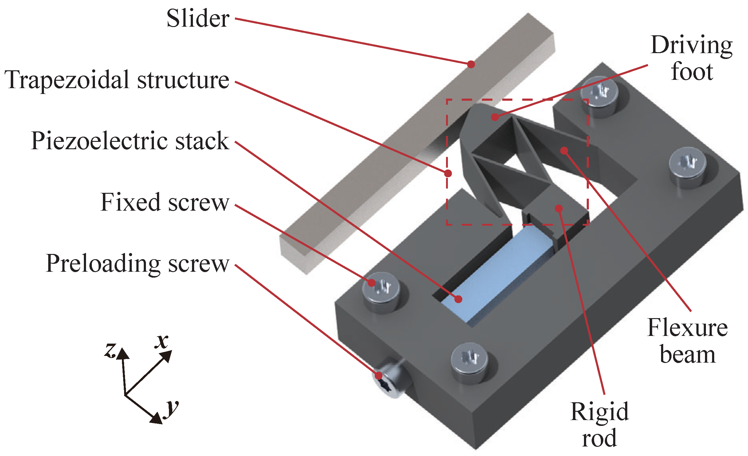
2.1. Mechanism Design
2.2. Working Principle
- (i)
- Initial phase (): When no voltage is applied to the piezoelectric stack, the system remains in its initial position, as shown in Figure 2a. In this configuration, point E receives the input displacement from the piezoelectric stack, while the flexure beams are fixed at points A and D. The driving foot is in direct contact with the slider at point F. Before commencing operation, it is crucial to determine the necessary preloading force to ensure optimal performance.
- (ii)
- Stick phase (): A slowly ramped voltage is applied to the piezoelectric stack, causing slow extension along the x direction, as shown in Figure 2b. Through the W-shaped flexure beams, the driving foot moves from point F to point F’ at through the arc path. Zooming in, the tiny displacement in the y-direction is very obvious, which can effectively increase positive pressure to ensure that the friction is becoming stronger during this phase, thereby making the stick motion stable. Additionally, the trapezoidal driving foot presses against the slider with its wider base to maximize the contact area, which increases static friction, ensuring a robust grip for controlled forward motion. Then, the slider moves forward incrementally, adhering to the driving foot’s motion .
- (iii)
- Slip phase (): When the voltage is abruptly reduced, the piezoelectric stack rapidly retracts. The driving foot moves from point F’ back to point F at , as shown in Figure 2c. This fast retraction causes the driving foot to pull away faster than the slider can respond, momentarily overcoming static friction. As a result, dynamic friction decreases, allowing the foot to slip backward in relation to the slider. Due to inertia and the reduction in friction, the slider remains in its forward position, resulting in a net forward displacement. During this rapid retraction, the tapered geometry of the foot minimizes the contact area with the slider, further reducing dynamic friction. This asymmetry in frictional forces allows for minimal backward slippage of the slider, ultimately facilitating substantial net forward displacement.
3. Analysis and Optimization
- (i)
- Rigid rod: Width a of the rigid rod in the x direction; width b of the rigid rod in the y direction; width w of the rigid rod in the z direction.
- (ii)
- Flexure beam: Width of each flexure beam in the x direction; width of each flexure beam in the y direction; width w of each flexure beam in the z direction.
- (iii)
- Trapezoidal driving foot: Position of the top anchor point with respect to the middle point at bottom as c and h in x and y directions; radius r of the top fillet; height of left and right corners as and ; width w of the driving foot in the z direction.
- (i)
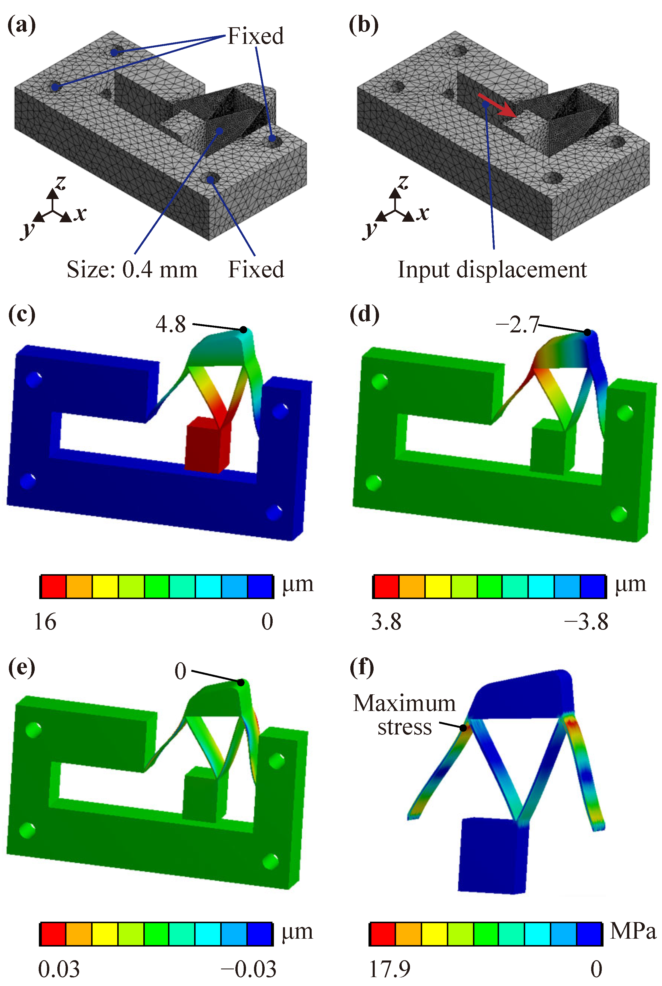
- For each set of parameters , the frictionless displacement and the first natural frequency are assessed via FEA with 44,894 elements.
- (ii)
- Improved NSGA-II algorithm is utilized to conduct optimization through genetic algorithm in MATLAB R2018b, i.e., the gamultiobj function, in which population size is set to be 200; the crossover fraction is set to be 0.8; the proportion of points on the Pareto front to the population is set to be 0.35.
- (iii)
- The convergence relative value is set to be 0.001, which is regarded as the iteration termination criterion. If the termination criteria are satisfied, the Pareto front solutions are populated; otherwise, the population will evolve.
- (iv)
- The child population is generated from the parent population through crossover and mutation. Divide their merged population into multiple ranks, which represent the superiority of the objectives, and calculate the crowding distance among individuals of the same rank, which represents the distribution range. The individuals with low rank and high crowding distance are prioritized for pruning.
4. Results
4.1. Static Performances
- (i)
- The driving foot of the actuator exhibits a notable displacement of 4.8 µm, as depicted in Figure 6c. This measurement confirms the actuator’s exceptional capability to generate motion effectively along the intended axis. The displacement observed along the x-axis signifies the actuator’s effective step size during the stick phase, which directly influences both motion resolution and the load capacity that can be handled.
- (ii)
- In terms of directional deformation along the y-axis, the measurement stands at 2.7 µm, as portrayed in Figure 6d. This particular displacement indicates a vertical movement toward the slider component, suggesting that the normal pressure exerted on the slider increases throughout the stick phase, thereby leading to a rise in static friction that must be overcome for movement.
- (iii)
- It is noteworthy that the z-axis deformation is minimal, as illustrated in Figure 6e, which serves to emphasize the design’s robustness and inherent stability against out-of-plane forces that could potentially compromise operational integrity.
4.2. Dynamic Performances
5. Conclusions
Author Contributions
Funding
Institutional Review Board Statement
Informed Consent Statement
Data Availability Statement
Conflicts of Interest
References
- Dou, W.; Zhong, G.; Yang, J.; Shen, J. Design and modeling of a hybrid soft robotic manipulator with compliant mechanism. IEEE Robot. Autom. Lett. 2023, 8, 2301–2308. [Google Scholar] [CrossRef]
- Liang, C.; Wang, F.; Huo, Z.; Shi, B.; Tian, Y.; Zhao, X.; Zhang, D. A 2-DOF monolithic compliant rotation platform driven by piezoelectric actuators. IEEE Trans. Ind. Electron. 2019, 67, 6963–6974. [Google Scholar] [CrossRef]
- Li, Y.; Ye, T.; Ling, J.; Xiao, X.; Feng, Z. A novel F-shaped linear guiding mechanism based compliant positioning stage with restricted parasitic motion. Precis. Eng. 2024, 88, 674–685. [Google Scholar] [CrossRef]
- Ye, T.; Feng, Z.; Ling, J.; Li, Y. A novel w-shaped flexure-guided mechanism for high-frequency piezo-actuated micromanipulations. IEEE/ASME Trans. Mechatron. 2024. [Google Scholar] [CrossRef]
- Yu, X.; Cheng, H.; Zhang, M.; Zhao, Y.; Qu, L.; Shi, G. Graphene-based smart materials. Nat. Rev. Mater. 2017, 2, 17046. [Google Scholar] [CrossRef]
- Zhou, X.; Wu, S.; Wang, X.; Wang, Z.; Zhu, Q.; Sun, J.; Huang, P.; Wang, X.; Huang, W.; Lu, Q. Review on piezoelectric actuators: Materials, classifications, applications, and recent trends. Front. Mech. Eng. 2024, 19, 6. [Google Scholar] [CrossRef]
- Ling, J.; Ye, T.; Feng, Z.; Zhu, Y.; Li, Y.; Xiao, X. A survey on synthesis of compliant constant force/torque mechanisms. Mech. Mach. Theory 2022, 176, 104970. [Google Scholar] [CrossRef]
- Qiao, G.; Li, H.; Lu, X.; Wen, J.; Cheng, T. Piezoelectric stick-slip actuators with flexure hinge mechanisms: A review. J. Intell. Mater. Syst. Struct. 2022, 33, 1879–1901. [Google Scholar] [CrossRef]
- Xu, Z.; Sun, W.; Li, X.; Huang, H.; Dong, J. A stick-slip piezoelectric actuator with high assembly interchangeability. Int. J. Mech. Sci. 2022, 233, 107662. [Google Scholar] [CrossRef]
- Lin, Y.; An, D.; Lin, Z.; Chen, X.; Huang, W. Progress in high-performance stick-slip piezoelectric actuators: A review. Int. J. Smart Nano Mater. 2024, 15, 652–696. [Google Scholar] [CrossRef]
- Howell, L.L. Compliant mechanisms. In 21st Century Kinematics: The 2012 NSF Workshop; Springer: London, UK, 2013; pp. 189–216. [Google Scholar]
- Chi, Y.; Li, Y.; Zhao, Y.; Hong, Y.; Tang, Y.; Yin, J. Bistable and multistable actuators for soft robots: Structures, materials, and functionalities. Adv. Mater. 2022, 34, 2110384. [Google Scholar] [CrossRef] [PubMed]
- Ling, M.; Howell, L.L.; Cao, J.; Chen, G. Kinetostatic and dynamic modeling of flexure-based compliant mechanisms: A survey. Appl. Mech. Rev. 2020, 72, 030802. [Google Scholar] [CrossRef]
- Ma, X.; Liu, Y.; Deng, J.; Gao, X.; Cheng, J. A compact inchworm piezoelectric actuator with high speed: Design, modeling, and experimental evaluation. Mech. Syst. Signal Process. 2023, 184, 109704. [Google Scholar] [CrossRef]
- Dai, C.; Xin, L.; Zhang, Z.; Shan, G.; Wang, T.; Zhang, K.; Wang, X.; Chu, L.T.; Ru, C.; Sun, Y. Design and control of a piezo drill for robotic piezo-driven cell penetration. IEEE Robot. Autom. Lett. 2019, 5, 339–345. [Google Scholar] [CrossRef]
- Zhu, B.; Zhang, X.; Zhang, H.; Liang, J.; Zang, H.; Li, H.; Wang, R. Design of compliant mechanisms using continuum topology optimization: A review. Mech. Mach. Theory 2020, 143, 103622. [Google Scholar] [CrossRef]
- Ye, T.; Ling, J.; Kang, X.; Feng, Z.; Xiao, X. A novel two-stage constant force compliant microgripper. J. Mech. Des. 2021, 143, 053302. [Google Scholar] [CrossRef]
- Xie, Y.; Li, Y.; Cheung, B.C. A new symmetrical Z-shaped compliant linear actuator based on parasitic motion principle. Smart Mater. Struct. 2022, 31, 125017. [Google Scholar] [CrossRef]
- Qiu, C.; Ling, J.; Zhang, Y.; Ming, M.; Feng, Z.; Xiao, X. A novel cooperative compensation method to compensate for return stroke of stick-slip piezoelectric actuators. Mech. Mach. Theory 2021, 159, 104254. [Google Scholar] [CrossRef]
- Xu, Z.; Huang, H.; Dong, J. A stick-slip piezoelectric actuator with measurable contact force. Mech. Syst. Signal Process. 2020, 144, 106881. [Google Scholar] [CrossRef]
- Zhong, B.; Liao, Z.; Hu, H.; Liu, S.; He, C.; Sun, L. A review of recent studies on piezoelectric stick-slip actuators. Precis. Eng. 2025, 94, 175–190. [Google Scholar] [CrossRef]
- Cheng, T.; He, M.; Li, H.; Lu, X.; Zhao, H.; Gao, H. A novel trapezoid-type stick–slip piezoelectric linear actuator using right circular flexure hinge mechanism. IEEE Trans. Ind. Electron. 2017, 64, 5545–5552. [Google Scholar] [CrossRef]
- Zhang, Y.; Peng, Y.; Sun, Z.; Yu, H. A novel stick–slip piezoelectric actuator based on a triangular compliant driving mechanism. IEEE Trans. Ind. Electron. 2018, 66, 5374–5382. [Google Scholar] [CrossRef]
- Huang, H.; Xu, Z.; Wang, J.; Dong, J. A low frequency operation high speed stick-slip piezoelectric actuator achieved by using a L-shape flexure hinge. Smart Mater. Struct. 2020, 29, 065007. [Google Scholar] [CrossRef]
- Yu, Y.; Gao, Q.; Qiao, G.; Zhang, X.; Lu, X.; Cheng, T. A direction-guidance hybrid excitation method for inertial flexible hinge piezoelectric actuator with high speed performance. Sens. Actuators A Phys. 2020, 314, 112229. [Google Scholar] [CrossRef]
- Pan, Q.; Hu, J.; Miao, E.; Chen, S.; Shu, S.; Hu, P.; Huang, B. Novel piezoelectric rotary motor driven by a single-phase sine wave with an asymmetric stator. Sens. Actuators A Phys. 2019, 90, 075006. [Google Scholar] [CrossRef]


| Parameter | Lower Value | Upper Value | Optimized Value | Unit |
|---|---|---|---|---|
| a | 5 | 10 | 5.02 | mm |
| b | 7 | 10 | 6.72 | mm |
| 4 | 10 | 4.33 | mm | |
| 7 | 15 | 9.58 | mm | |
| t | 0.4 | 1 | 0.42 | mm |
| w | 6 | 20 | 6 | mm |
| c | 0.5 | 5 | 3.52 | mm |
| h | 4 | 10 | 5.34 | mm |
| 3 | 10 | 3 | mm | |
| 0 | 10 | 0.11 | mm | |
| r | 0.5 | 2 | 1.05 | mm |
Disclaimer/Publisher’s Note: The statements, opinions and data contained in all publications are solely those of the individual author(s) and contributor(s) and not of MDPI and/or the editor(s). MDPI and/or the editor(s) disclaim responsibility for any injury to people or property resulting from any ideas, methods, instructions or products referred to in the content. |
© 2025 by the authors. Licensee MDPI, Basel, Switzerland. This article is an open access article distributed under the terms and conditions of the Creative Commons Attribution (CC BY) license (https://creativecommons.org/licenses/by/4.0/).
Share and Cite
Ye, T.; Feng, Z.; Li, Y. Design and Optimization of a Piezoelectric Stick-Slip Actuator with Distributed Compliance. Machines 2025, 13, 460. https://doi.org/10.3390/machines13060460
Ye T, Feng Z, Li Y. Design and Optimization of a Piezoelectric Stick-Slip Actuator with Distributed Compliance. Machines. 2025; 13(6):460. https://doi.org/10.3390/machines13060460
Chicago/Turabian StyleYe, Tingting, Zhao Feng, and Yangmin Li. 2025. "Design and Optimization of a Piezoelectric Stick-Slip Actuator with Distributed Compliance" Machines 13, no. 6: 460. https://doi.org/10.3390/machines13060460
APA StyleYe, T., Feng, Z., & Li, Y. (2025). Design and Optimization of a Piezoelectric Stick-Slip Actuator with Distributed Compliance. Machines, 13(6), 460. https://doi.org/10.3390/machines13060460