Article

Nonlinear Dynamic Modeling of a Gear-Bearing Transmission System Based on Dynamic Meshing Parameters

1
School of Astronautics, Harbin Institute of Technology, Harbin 150001, China
2
School of Mechanical Science and Engineering, Northeast Petroleum University, Daqing 163000, China
3
Department of Physics and Engineering Mathematics, Faculty of Electronic Engineering, Menoufia University, Menouf 32952, Egypt
4
Applied Science Research Center, Applied Science Private University, Amman 11937, Jordan
*
Author to whom correspondence should be addressed.
Machines 2025, 13(3), 230; https://doi.org/10.3390/machines13030230
Submission received: 15 February 2025 / Revised: 6 March 2025 / Accepted: 7 March 2025 / Published: 12 March 2025

Abstract

:
The nonlinear contact force between gears and bearings exhibits intricate dynamics. This paper focuses on the coupling relationship between the time-varying meshing parameters of the gears, dynamic backlash, and dynamic bearing clearance in gear-bearing transmission systems. A dynamic model of a gear-bearing transmission system considering dynamic meshing parameters is established. The coupling mechanism between meshing stiffness, gear backlash, bearing clearance, and gear vibration response in gear transmission systems is analyzed. The results demonstrate a negative correlation between the gears’ geometric center distance and meshing stiffness amplitude. Gear vibration can affect the relative position of the gears. Changes in the relative position of the gears lead to an increase in the number of frequency components in the frequency domain of gear meshing stiffness. During gear rotation, the meshing parameters of the gears and tooth side clearance fluctuate with gear vibration. With increasing speed, the model’s dynamic meshing parameters also increase accordingly. The model achieves a feedback calculation of the system parameters and vibration responses in gear-bearing system dynamics.

1. Introduction

Gear-bearing transmission systems are extensively utilized in aviation, maritime vessels, automobiles, and various other mechanical applications. As the mechanical systems field advances, there is an increasing demand for enhanced vibration and noise control in these transmission systems. Given the multitude of nonlinear factors and complex dynamic interactions present in gear-bearing systems, developing a highly accurate dynamic model is essential.
In the modeling and analysis of the gear-bearing transmission system, time-varying meshing stiffness (TVMS) plays a crucial role. To develop more precise gear dynamic models, it is essential to employ more accurate methods for calculating TVMS. Among the numerous TVMS calculation methods, the finite element method has become a commonly used approach for calculating gear time-varying mesh stiffness (TVMS) due to its characteristics of high precision and speed [1]. Yang et al. [2] assumed that each tooth is a cantilever structure with an involute cross section and calculated gear TVMS through four components. Tian et al. [3] considered the effect of shear potential energy on the engagement stiffness based on Yang. Zhou [4] went a step further by considering the impact of the variable surface energy of the gear matrix on the meshing stiffness building on the work of Yang and Tian. Chen [5] further developed a gear TVMS calculation model that takes gear deviations into account. Ma [6] considered the TVMS of gears with different tooth profiles and calculated gear TVMS by dividing the variable cross-section profile into the involute and root fillet curves. All these studies regarded each parameter of the gear as a fixed value. Luo [7] established a gear TVMS calculation model when the center distance of the gears changes. He Dai [8] established a gear TVMS model considering tooth top modification and variable load conditions but the tooth profile of this model ignored the tooth root transition curve. From the above work, it can be understood that most papers consider the meshing parameters as constants when calculating the gear TVMS. Yang [9] and Liu [10] developed a time-varying mesh stiffness (TVMS) model that takes into account transmission errors and the transition curve of the tooth root. This model enhances the accuracy of stiffness predictions during gear engagement by considering the dynamic interactions between meshing teeth. Nevertheless, due to gear vibrations or other factors affecting gear meshing stiffness, the meshing parameters may vary in real time. Guo [11] investigated the time-varying back-mesh stiffness and its correlation with the tooth gap. Cheng [12] proposed a method for calculating the gear meshing stiffness under mixed lubrication. Hence, there is a need to develop a more precise TVMS model for gear meshing that takes into account dynamic meshing parameters. In previous research on gear dynamic modeling, in addition to considering time-varying mesh stiffness, gear dynamic models considering different factors were also proposed.
Blankenship and Kahraman [13] present a solver based on the harmonic balance method for nonlinear gear systems with parameter-containing excitations and backlash types. Kahraman [14] further studied the subharmonic and chaotic motions of a gear system containing a backlash using a multinomial harmonic balance method. Chen [15] used the fractal method, fixed value method, and positronic distribution, respectively, to represent the gear clearance, and the comparison yielded the fractal method as the more optimal solution. Cao et al. [16] devised a dynamic gear model that accounts for the gear eccentricity error. Zhao [17] formulated a dynamic model for gear systems, considering geometric eccentricity and the dynamic center distance. Han [18] established a collision model for gear shafts and bushings, taking into account bearing clearance. Liu [19] explored a dynamic model for spur gears incorporating pitch deviation, revealing its influence on the gear pair’s dynamic response by altering meshing conditions. Meng [20] constructed a gear dynamic model encompassing cracked and spalled gears, examining how the system’s dynamic displacement changes during fault progression. Han [21] proposed a dynamic gear-shaft bearing housing model that considered gear shaft cracking and peeling faults.
Many studies have confirmed the nonlinearity of bearing stiffness. Fukata et al. [22] conducted a detailed analysis of the impact of changes in the cage circumferential position and radial clearance of bearings on bearing stiffness. Sawalhi and Randall [23] explored the influence of extended faults occurring in the inner and outer raceways of rolling element bearings on gear-bearing systems. Tu [24] established a bearing dynamic model in which the contact forces between different parts of the rolling elements were considered as functions of the gravity and centrifugal forces acting on the rolling elements. Zhang [25] proposed a dynamic model considering bearing waviness and obtained the stiffness of angular contact bearings. Bizarre [26] developed a nonlinear dynamic model for angular contact ball bearings, which considered bearing lubrication. Xu et al. [27] established a bearing stiffness calculation model, which considered the misalignment of raceways. Eduardo Corral [28] introduced various contact force models, including the Hertzian contact model that neglects energy dissipation. Raúl Gismeros [29] Moreno proposed a modeling method for deep groove ball bearings with planar radial loads based on the dynamics of multibody systems. The method focuses on the study of the Hertzian contact behavior of the bearing components (inner ring, outer ring, rolling elements, and cage) using a smooth contact model.
In recent years, scholars have researched gear-bearing systems’ bearing nonlinearity and meshing stiffness nonlinearity. Kim [30] proposed a gear dynamic model considering translational motion. Yi [31] developed a dynamic model for gear transmission systems, which considered dynamic backlash based on Kim’s work. However, both Yi and Kim only considered the influence of changes in the relative positions of the gears on the frequency of TVMS, overlooking its impact on the amplitude. Kong [32] developed a model for gear-bearing systems considering TVMS and nonlinear bearing forces. They found that the gear meshing state significantly affects the internal loads of the bearings. Guo [33] and Parker established an aggregated parameter model considering bearing clearance and variations in gear meshing stiffness to research the nonlinear behavior of the planetary gears inducing bearing clearances. Liu [34] considered both back contact forces and journal bearing forces in the presence of clockwise and counterclockwise rotations of gears in the gear system dynamics model. Zhang [35] developed a planetary gear system model considering bearing clearances and computed the variations in system loads under different radial bearing errors and clearance ratios. Xu [36] investigated the dynamic vibration response of gears with different radial clearance bearings. Haonan Li [37] proposed a dynamic model based on gear compatibility conditions. Zeng [38] proposed a gear-bearing dynamics model considering bearing interference fits. Tian [39] contributed to the dynamic modeling and stability analysis of a spur gear system considering gear backlash and bearing clearance. Xu [40] developed a gear model using tooth spacing to simulate angular contact. Guan [41] established a gear-bearing dynamics model considering bearing friction. Nevertheless, these models ignore the situation that the gear clearance also changes when the gear meshing parameters change and the spring is equivalent to a linear spring. Accordingly, the nonlinear coupling between time-varying bearing stiffness and TVMS in gear-bearing transmission systems requires more systematic research.
The motivation of this article is to present a novel gear TVMS by considering the dynamic meshing parameters. Gear vibration causes variations in gear meshing parameters, gear backlash, and bearing clearance. A nonlinear dynamic model of the gear-bearing transmission system with dynamic meshing parameters is established by incorporating these factors. This model can be used to analyze the coupling relationship between meshing parameters and gear meshing stiffness. Furthermore, the impact of gear vibration on meshing parameters, dynamic gear backlash, and dynamic bearing clearance in the gear-bearing transmission system is also investigated.
The rest of this paper is organized as follows. In Section 2, the calculation model of gear meshing stiffness under dynamic meshing parameters is established. Then, in Section 3, the dynamic model of dynamic clearance ball bearing is established. In Section 4, the dynamic equations of the gear-bearing transmission system are derived, which are coupled with dynamic meshing parameters, dynamic gear clearance, dynamic bearing clearance, and gear mass eccentricity. Finally, in Section 5, the dynamic vibration response of a dynamic model—where parameters such as the pressure angle, offset angle, center distance, and contact ratio are treated as variables—is calculated and compared with the results obtained when these parameters are treated as constants.
Furthermore, the new model’s variation in the vibration response of the driven wheel under different gear speeds and initial bearing clearances is also analyzed.

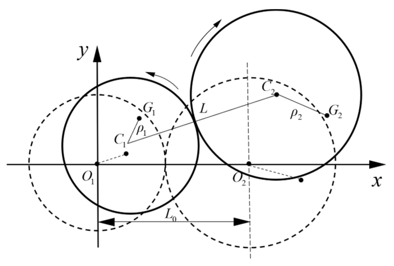
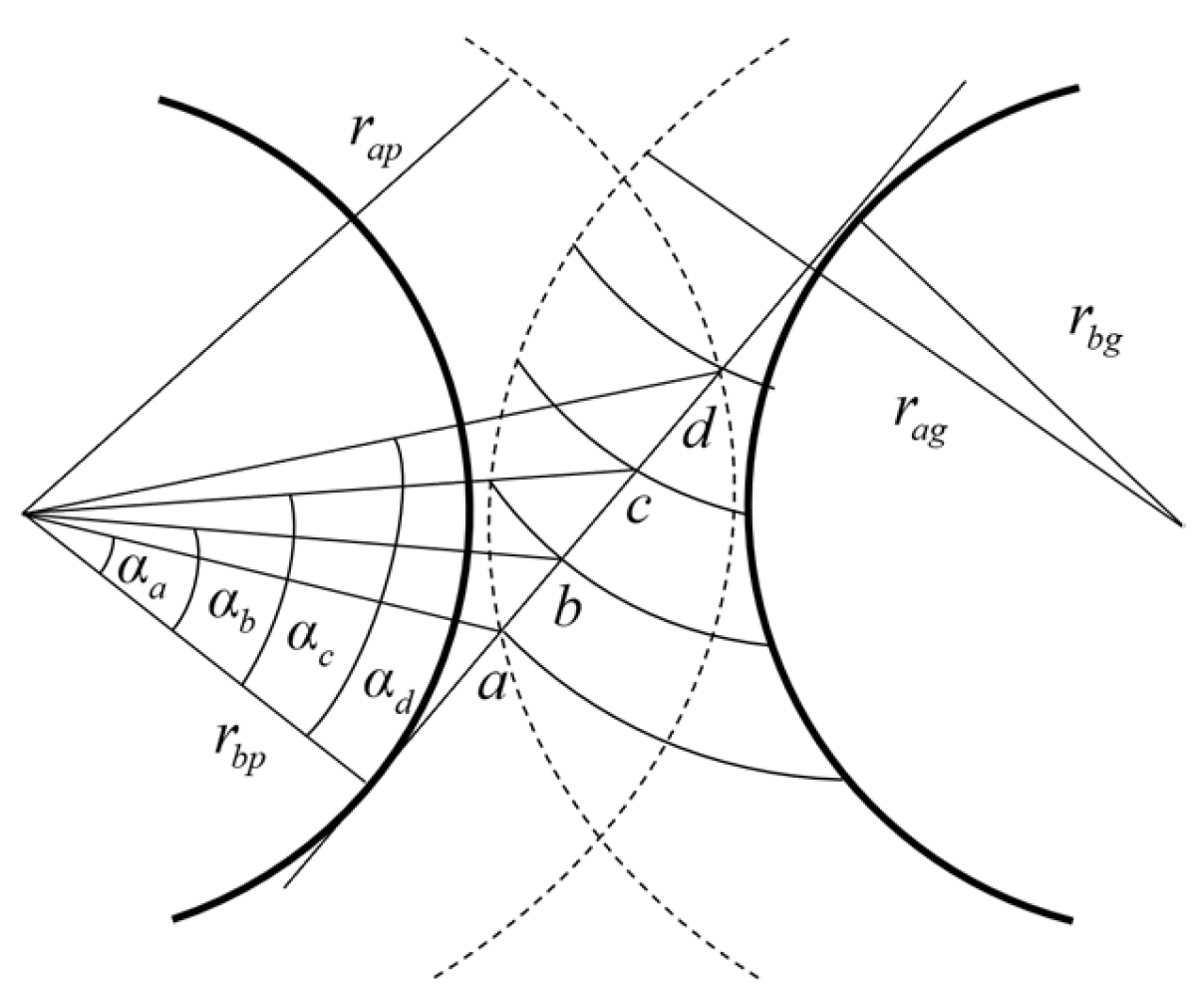
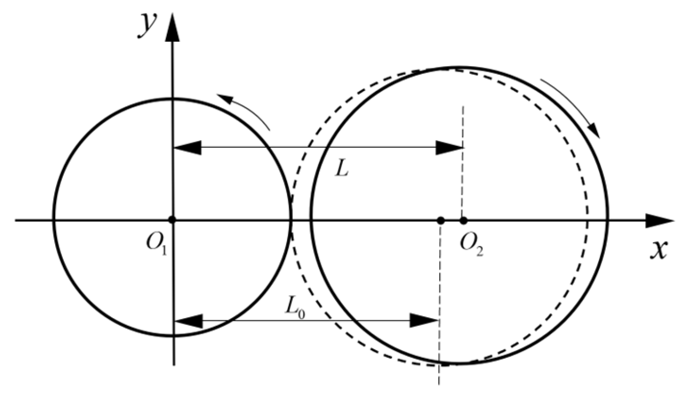
2. Spur Gear Meshing Stiffness Model

This paper investigates a transmission system consisting of a pair of involute gears and bearings. It assumes the gears are rigid and can only move within the xoy-plane. A diagram of the relative positions of the gear transmission system at the previous and current time steps [30] is shown in Figure 1. The dashed lines represent the position of the gear transmission system at the previous moment, while the solid lines indicate its position at the next moment. The geometric centers of the gears are C 1 and C 2 , respectively, and the initial center distance of the gears is L 0 . The centers of mass are G 1 and G 2 , respectively. The gears exhibit mass eccentricity, with mass eccentric distances of ρ 1 and ρ 2 , respectively. The geometric centers of the active and driven wheels at the initial moment are O 1 0 , 0 and O 2 L 0 , 0 , and at the next moment, the geometric centers become C 1 x p ,   y p and C 2 x g ,   y g .
Due to the changes in the relative positions of the geometric centers of the driving and driven wheels—resulting in a change in the center distance L and the angle of deflection β , which leads to changes in the angle of engagement—this results in a change in instantaneous pressure angle α . Assuming a positive counterclockwise direction of rotation, L and β are denoted as follows:
L = L 0 + x g x p 2 + y g y p 2
β = tan 1 y g y p / L 0 + x g x p
α = cos 1 r b p + r b g / L
where L 0 denotes the initial center distance; r b is the radius of the base circle; r a is the radius of the tooth apex circle; and the subscripts p and g indicate the master and follower wheels, respectively.
In the process of gear movement, there will be a single-tooth and double-tooth alternate mesh. The single-tooth mesh and double-tooth mesh intervals are expressed by the instantaneous pressure angle α p j , while the gear master wheel instantaneous pressure angle α p j ± 1 and the slave wheel pressure angle α g j ± 1 can be obtained through the gear geometric relationship. α 0 is the standard pressure angle.
w ( t ) represents the angle of rotation of the driving gear as a function of time. The angle of rotation of the driving gear is positively correlated with time; therefore, in this paper, w ( t ) refers to the rotational speed of the driving gear.
α p j = arctan s i g n ( β ) α 0 + β α + θ + tan a p
tan a p = t 1 t w ( t ) d t + tan a c
tan α p j ± 1 = tan α p j ± 2 π / z p
tan α g j ± 1 = L r b p sin α p g r b p + r b g r b p tan α p g r b g tan α p j ± 1 r b p
The double–single–double intervals in a meshing cycle are represented by the geometric relations of the gears in Figure 2. The double-tooth–single-tooth–double-tooth intervals correspond to the d-c, c-b, and b-a segments of the straight line ad, respectively, and the boundary points of the instantaneous pressure angles are denoted, respectively, as α a , α b , α c , and α d , where φ = 2 π / Z p denotes the angle corresponding to a single tooth and Z p denotes the number of teeth of the main wheel.
tan α a = L 2 r b p + r b g 2 r a g 2 r b g 2 / r b p
tan α b = tan α d + φ
tan α c = tan α a φ
cos α d = r b p / r a p
In this paper, the TVMS of the gears is calculated [42] based on the improved potential energy method. The TVMS of the gears is calculated based on the tooth profile, which is divided into an involute region and a transitional curve section. The meshing stiffness of each pair of teeth in the single-tooth meshing region can be expressed as the sum of the stiffnesses of each part of the active and passive gears.
1 k m = 1 k h + i = 1 2 1 k a i + 1 k b i + 1 k s i + 1 k f i
In Equation (12), the subscripts i = 1, 2 represent the driver gear and the driven gear.
The two-tooth meshing interval stiffness can be expressed as Equation (13).
1 k m = j = 1 2 1 k h , j + i = 1 2 1 k a i , j + 1 k b i , j + 1 k s i , j + 1 k f i , j
In Equation (13), the subscripts j = 1, 2 denote the upper pair of meshing teeth and the lower pair of meshing teeth, respectively.
Among them, the contact stiffness k h , bending stiffness k b , shear stiffness k s , compression stiffness k a , and matrix stiffness k f are expressed as Equations (14)–(18).
k h = π E B 4 1 v 2
1 k b = π 2 α 0 cos α 1 l y 1 h sin α 1 2 E I y 1 d y 1   d γ d γ + α 1 α 2 3 1 + cos α 1 α 2 α sin α cos α 2 α 2 α cos α 2 E B sin α + α 2 α cos α 3 d α
1 k s = π 2 α 0 1.2 cos 2 α 1 G A y 1 d y 1   d γ d γ + α 1 α 2 1.2 ( 1 + v ) α 2 α cos α   cos 2 α 1 E B sin α + α 2 α cos α d α
1 k a = π 2 α 0 sin 2 α 1 E A y 1 d y 1   d γ d γ + α 1 α 2 α 2 α cos α sin 2 α 1 2 E B sin α + α 2 α cos α d α
1 k f = cos 2 α f E B P 01 u f S f 2 + P 02 u f S f + P 03 1 + P 04 tan 2 α f
where α 0 represents the standard pressure angle; α f , u f , S f , P 01 , P 02 , P 03 , and P 04 can be found in Ref. [42]; and G , A y 1 , I y 1 , d y 1   d γ , l , and h can be seen in Appendix A.
The above calculation of gear mesh stiffness involves numerous integral formulas. To facilitate the subsequent calculation of TVMS and system response in a convenient and efficient manner, fitting curves for single-tooth stiffness and pair-mesh stiffness with varying pressure angles at the contact point were developed, as illustrated in Figure 3. The specific geometric and material parameters of the gear pair are outlined in Table 1.

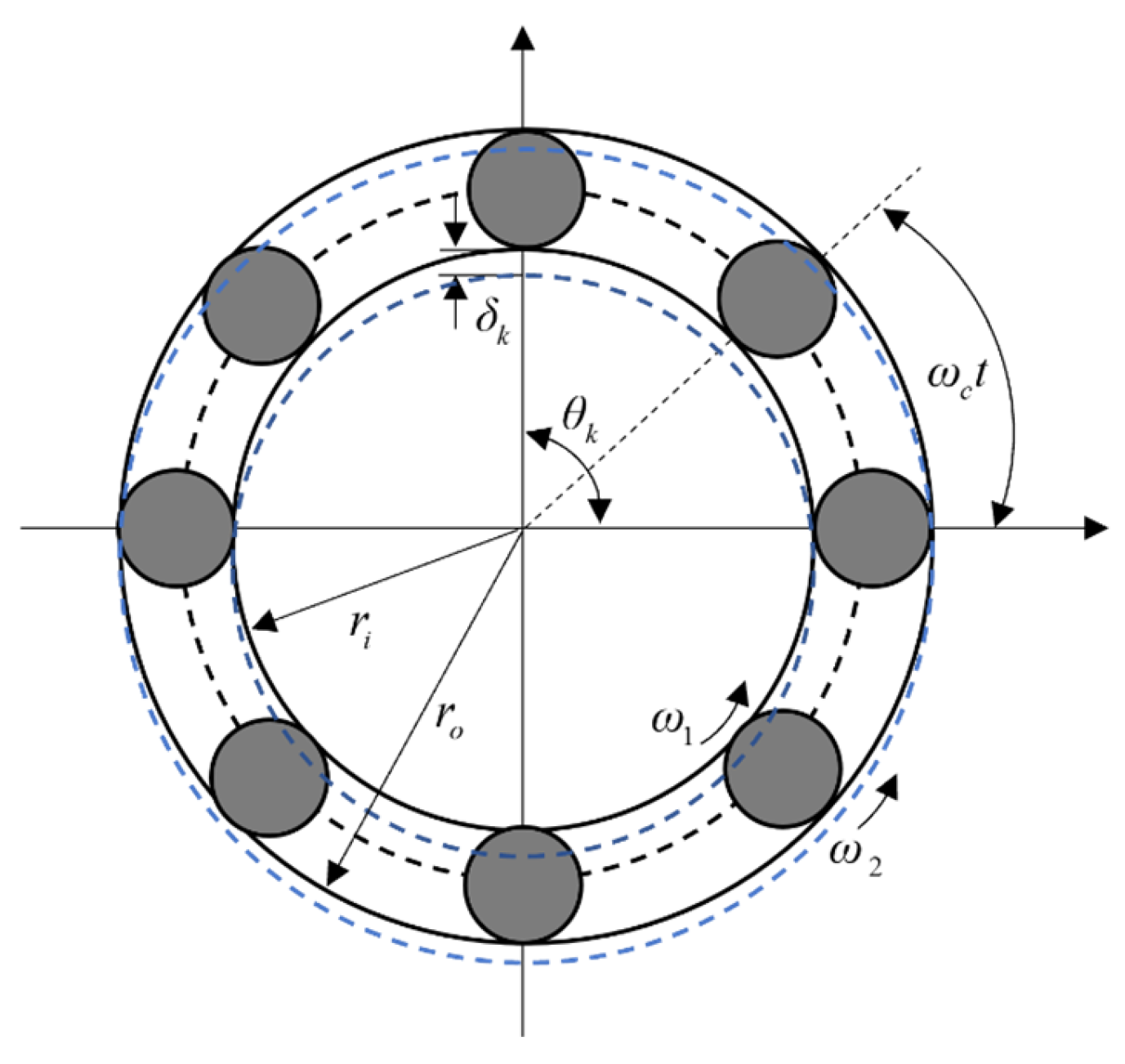
3. Bearing Mechanics Model

The bearings [43,44,45,46] used in this paper are all ball bearings. Ball bearings serve as supports for the gear system, encompassing numerous nonlinear factors such as fractional-order restoring forces, clearances, and variable stiffness excitations. Their structure schematic diagrams are shown in Figure 4.
This paper assumes that the bearing connected to the master wheel behaves as a nonlinear spring with dynamic bearing clearance, while the bearing connected to the driven wheel behaves as a linear spring. Assuming that the balls are purely rolling between the outer inner and ring, in each location, there are small deformations. At this point, the angular displacement of the kth ball is denoted as θ k , where N b is the number of balls, k = 1 ,   2 ,   ,   N b . The specific structural parameters are listed in Table 2.
The relative position relationship between the center of the kth ball and the inner and outer raceways is given by Equation (19).
δ k = x i x o cos θ k + y i y o sin θ k δ 0 , k = 1 ,   2 ,   ,   N b
where ω 1 , ω 2 , and ω c represent the speeds of the inner race, outer race, and cage of the ball bearings, respectively; o and i denote the outer and inner races of the bearing.
By neglecting the displacement of the bearing’s outer ring, Equation (19) is simplified to Equation (20). In this paper, since the outer ring of the bearing is connected to the gear hub and the inner ring is chosen to be in contact with the ground, the displacement of the bearing’s inner ring is zero, while the displacement of the outer ring is consistent with that of the connected gear.
δ k = x o cos θ k + y o sin θ k δ 0 , k = 1 ,   2 ,   ,   N b
where
θ k = 2 π k 1 / N b + ω c t
ω c = ω 1 r i / ( r i + r o )
where δ 0 represents the initial clearance of the ball bearing. The expression for the nonlinear force of the ball bearing can be represented as Equation (23).
F b x F b y = K b e a r k = 1 N b δ k 3 / 2 H δ k cos θ k sin θ k
where K b e a r is the Hertz contact stiffness of each ball; H δ k serves as the criterion for determining the contact between each ball and the bearing; H x = 1 x 0 indicates that the kth roller is engaged with the raceway; and H x = 0 x < 0 indicates that the kth roller is disengaged from the raceway. x > 0 indicates that δ k > 0 in Equation (20), meaning that the deformation of the ball is greater than the initial bearing clearance, and at this point, the ball is in contact with both the inner and outer rings of the bearing. On the other hand, x < 0 indicates that the ball does not come into contact with the inner and outer rings of the bearing.

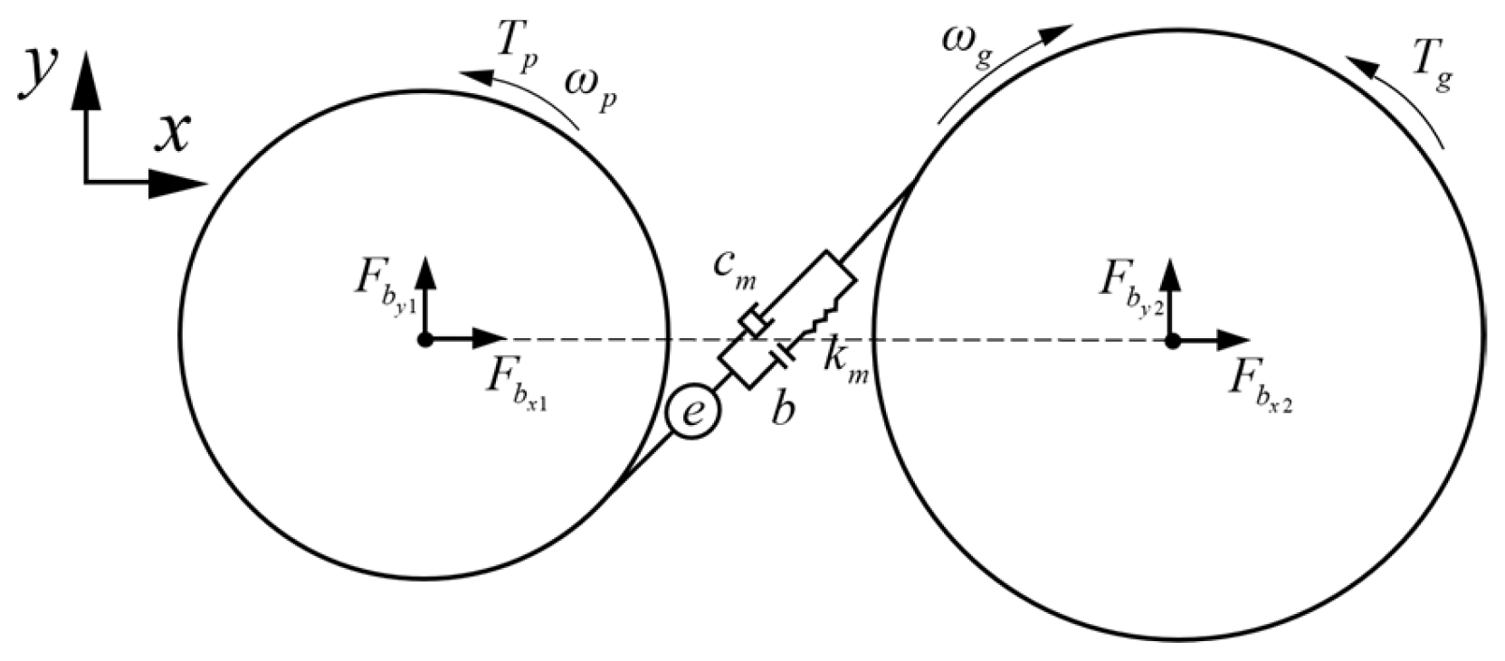
4. Dynamic Modeling of Gear-Bearing Systems
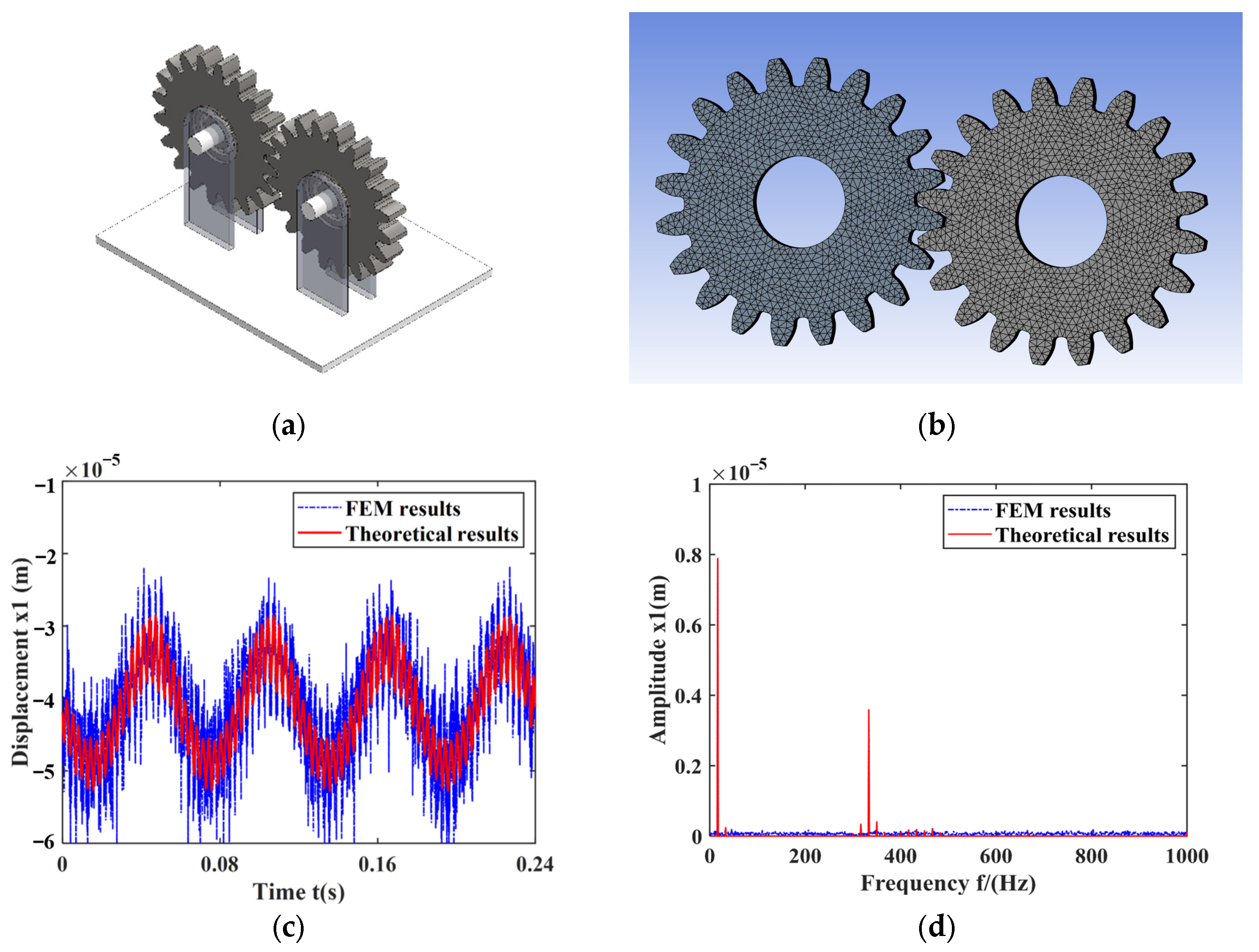
In this section, a dynamic model of the gear-bearing transmission system was established, considering factors such as coupled gear eccentricity, relative position changes caused by gear vibrations, dynamic variations in backlash, and dynamic changes in bearing clearance. The gear-bearing model established in this section neglects the friction, lubrication, and wear between the gears. Additionally, the gears only move in the xoy-plane along the vertical axis z direction and are treated as rigid bodies. The bearing friction, lubrication, and other dissipative energies are also neglected.
The dynamic model is described by six generalized coordinates, represented by vector q s , as shown in Equation (24).
q s = x p y p θ z p x g y g θ z g T
Based on the meshing relationship of involute spur gears [21], it is possible to derive the amount of deformation of the tooth flanks in the meshing plane of the gears δ d , which is also known as the dynamic transmission error. e t is the static transfer error.
δ d = x p x g sin α β + y p y g cos α β e t + r b p θ z p r b g θ z g
e t = e a sin ω p Z p t
where e a is the static transmission error amplitude; ω p is the rotational speed of the main wheel; r b p and r b g are the base circle radii of the driving wheel and the driven wheel, respectively; and Z p represents the number of teeth on the driving gear.
Due to tooth deformation and gear vibration during gear movement, it is necessary to design a specific gear clearance between the non-contacting tooth sides. Gear clearance is divided into the initial backlash produced by tooth thickness deviation and installation errors and the time-varying backlash produced by changes in the geometric center of the gear due to geometric eccentricity or vibration. Dynamic backlash b t is obtained by combining the two parts of the clearance according to the meshing relationship of the involute gears.
b t = b 0 + r b p + r b g [ tan α α tan α 0 α 0 ]
where b 0 is the initial half-scale side clearance.
The nonlinear differential equations of motion for the gear-bearing transmission system are established based on the mechanical equilibrium equations, as shown in Equation (28).
m p x p .. m p ρ p sin φ p θ z p .. + c x p x p . + F b x p = F d m F d m x p + m p ρ p φ p . 2 cos φ p m p y p .. + m p ρ p cos φ p θ z p .. + c y p y p . + F b y p = F d m F d m y p + m p ρ p φ p . 2 sin φ p m p g J p + m p ρ p 2 θ z p .. m p ρ p sin φ p x p .. + m p ρ p cos φ p y p .. = F d m F d m θ z p + T p m g x g .. m g ρ g sin φ g θ z g .. + c x g x g . + F b x g = F d m F d m x g + m g ρ g φ g . 2 cos φ g m g y g .. m g ρ g cos φ g θ z g .. + c y g x g . + F b x g = F d m F d m y g m g ρ g φ g . 2 sin φ g m g g J g + m g ρ g 2 θ z g .. m g ρ g sin φ g x g .. m g ρ g cos φ g y g .. = F d m F d m θ z g T g
where φ p and φ g are shown in Equation (29); F d m and F d m q s are shown in Appendix B.
φ p = ω p t + θ z p ,   φ g = Z g Z p ω p t + θ z g
The traditional gear dynamic models, such as Equation (30), however, do not take into account gear eccentricity, the dynamic variation in gear meshing parameters, or the linearization of bearings.
m p x p .. + c x p x p . + k x p x p + ( k m f + c m f 1 ) sin α = 0 m p y p .. + c y p y p . + k y p y p + ( k m f + c m f 1 ) cos α = m p g J p θ z p .. + ( k m f + c m f 1 ) r b p = T p m g x g .. + c x g x g . + k x g x g ( k m f + c m f 1 ) sin α = 0 m g y g .. + c y g y g . + k y g y g ( k m f + c m f 1 ) cos α = m g g J g θ z g .. ( k m f + c m f 1 ) r b g = T g

5. Results

The derivation and analysis of the equations in the preceding sections reveal that the gear-bearing transmission system is presented by various nonlinear solid and coupled factors. To accurately analyze the nonlinear and vibration characteristics of the system, it is essential to develop a more detailed mechanical model of the gear-bearing transmission system.
This section begins by calculating the gear TVMS under dynamic meshing parameters and analyzes the variation in gear meshing stiffness with changes in relative gear positions. Subsequently, the meshing stiffness calculation model is integrated into the gear-bearing system, allowing for a comparative analysis of the meshing states and vibration characteristics with the old model. Finally, the vibration characteristics of the system and the variations in the meshing parameters under different speeds and bearing clearances are analyzed.

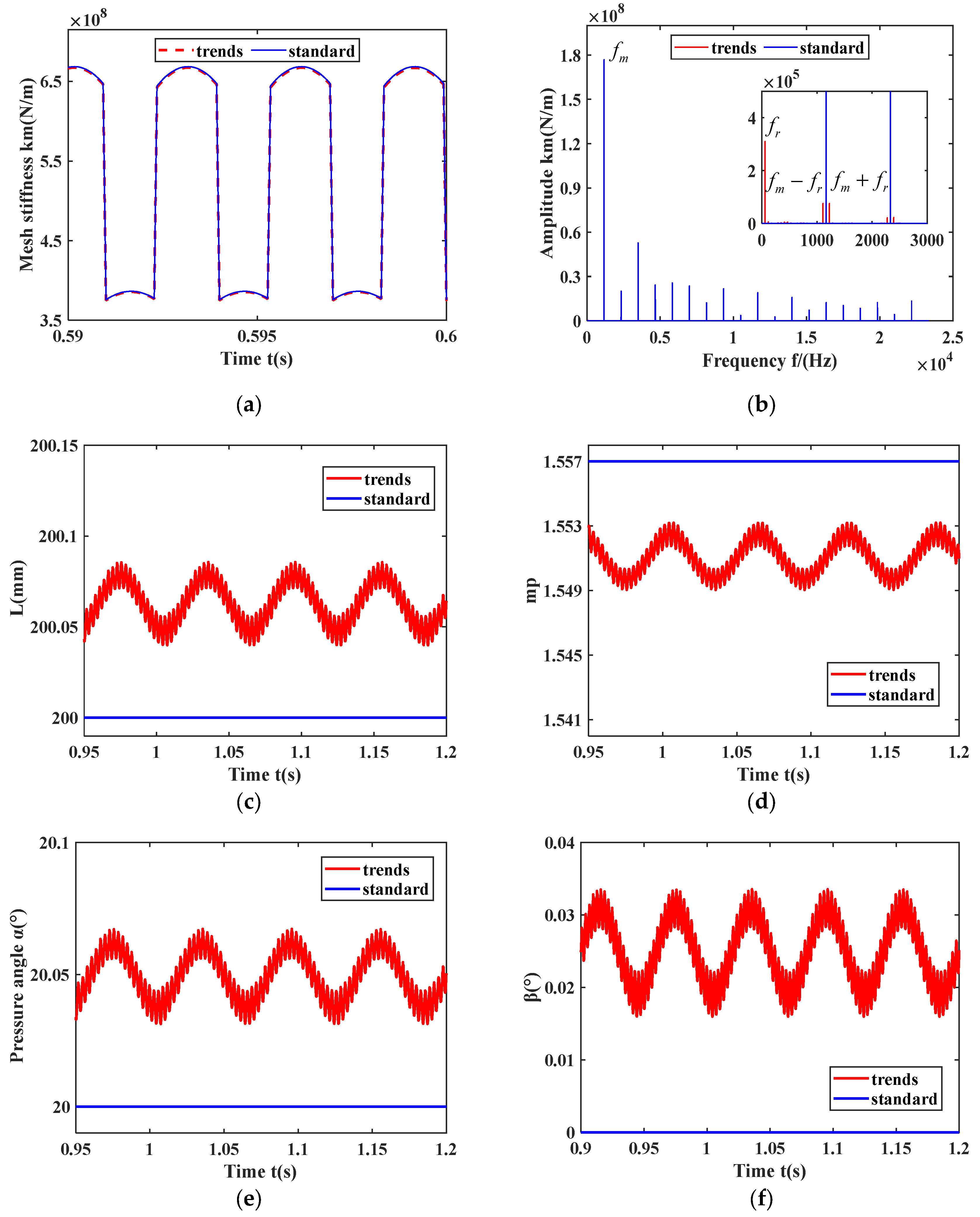
5.1. Gear Mesh Stiffness Calculation Based on Dynamic Meshing Parameters

To more intuitively observe the changes in gear meshing stiffness as the relative positions of the gears change—assuming that the master wheel rotates around its geometric center at 1000 r/min—the initial relative position of the gear transmission system is shown by the dashed lines in Figure 5, where the center distance of the gears is L, while the standard center distance is L0. The driven gear undergoes eccentric motion with an eccentricity of 0.5 mm. The parameters of the driving and driven gears are listed in Table 1. The computed gear meshing stiffness, meshing stiffness of amplitude–frequency, center distance, and overlap variation are displayed in Figure 6.
From Figure 6, it is evident that in the spectrum of the gear stiffness curve under the standard center distance, there is only the meshing frequency and multiplicative frequency of the gear meshing frequency. The gear meshing stiffness curve under the dynamic center distance shows periodic fluctuation—which leads to the change in the frequency of the meshing stiffness—from the meshing frequency and its multiplicative frequency to the rotational frequency, the meshing frequency, its combined frequency, and multiplicative frequency. The center distance shows a periodic change. At the initial moment, the center distance of the gears is at its minimum. At this point, the meshing stiffness is at its maximum. The center distance gradually increases to its maximum as the main wheel rotates to 180°, and the meshing stiffness gradually decreases to its minimum as the main wheel rotates from 180° to 360°.
Hence, it can be inferred that with the increase in the relative position of the gears, the amplitude of gear meshing stiffness decreases, the dual-tooth meshing interval shortens, while the single-tooth meshing interval lengthens. Furthermore, the meshing frequency increases.

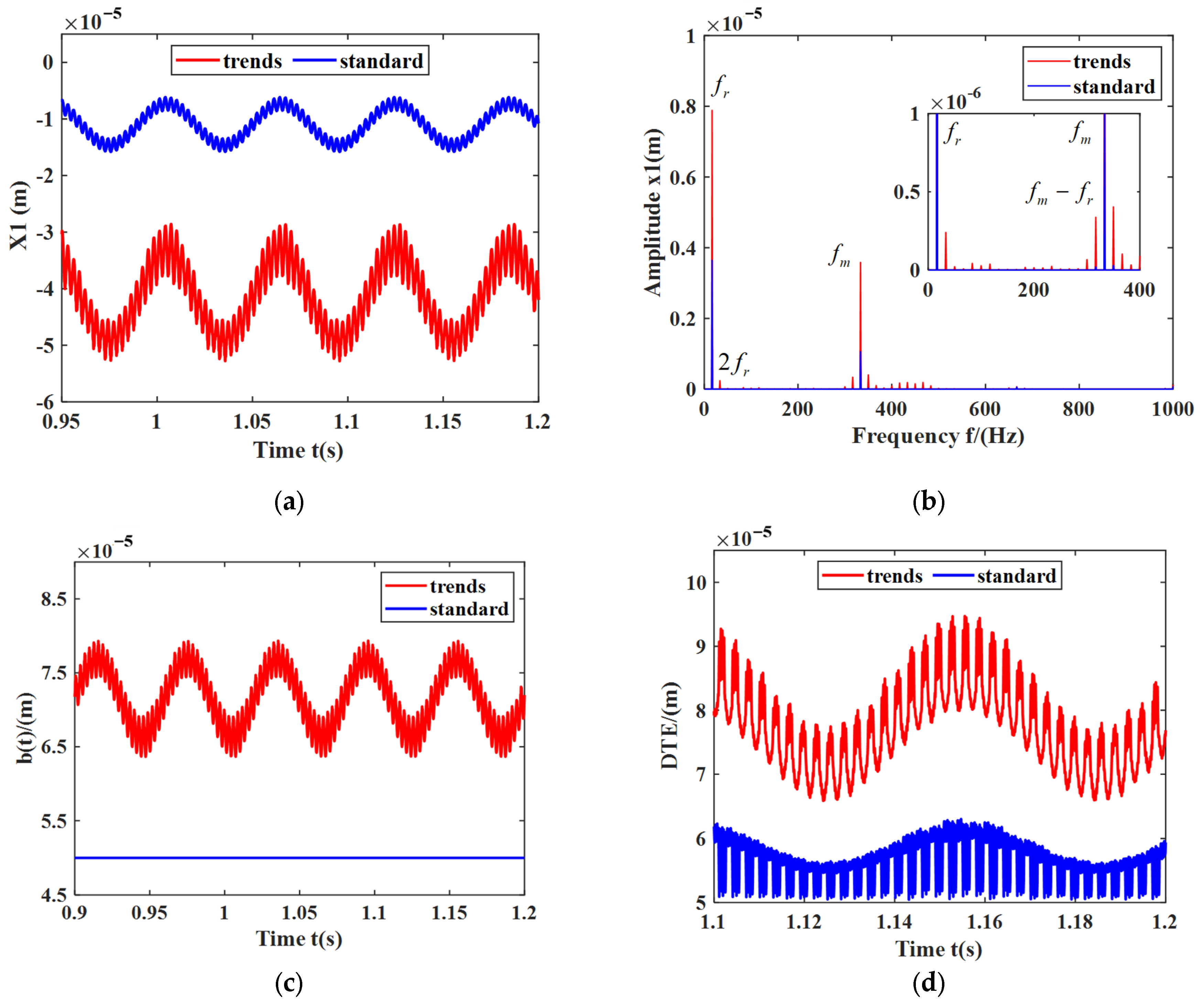
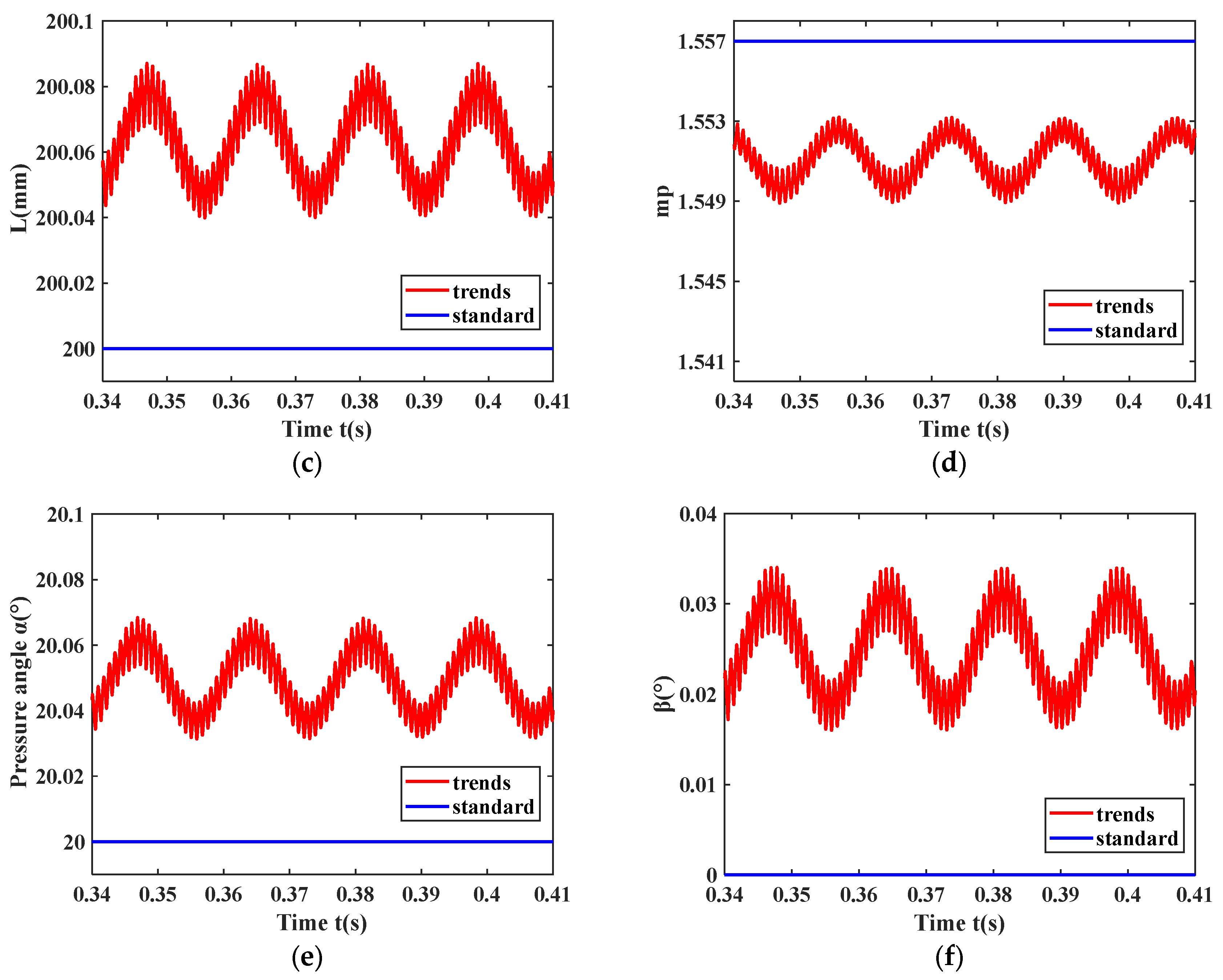
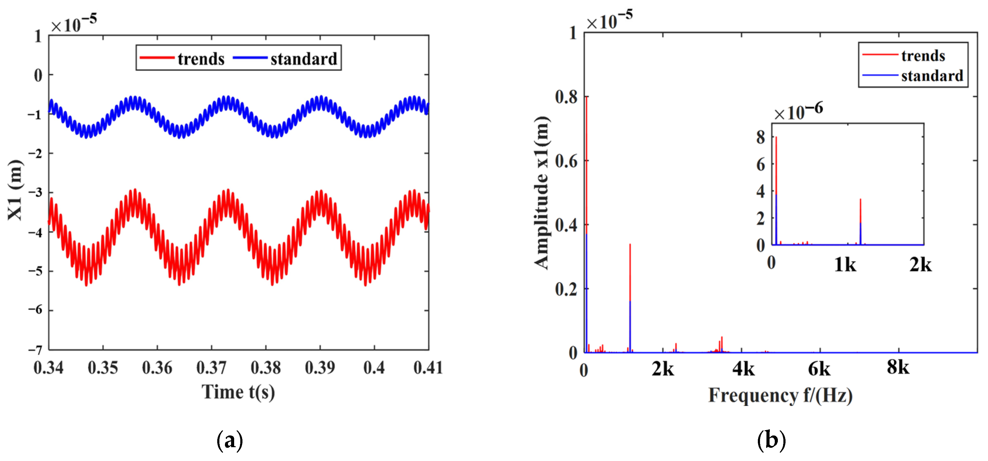
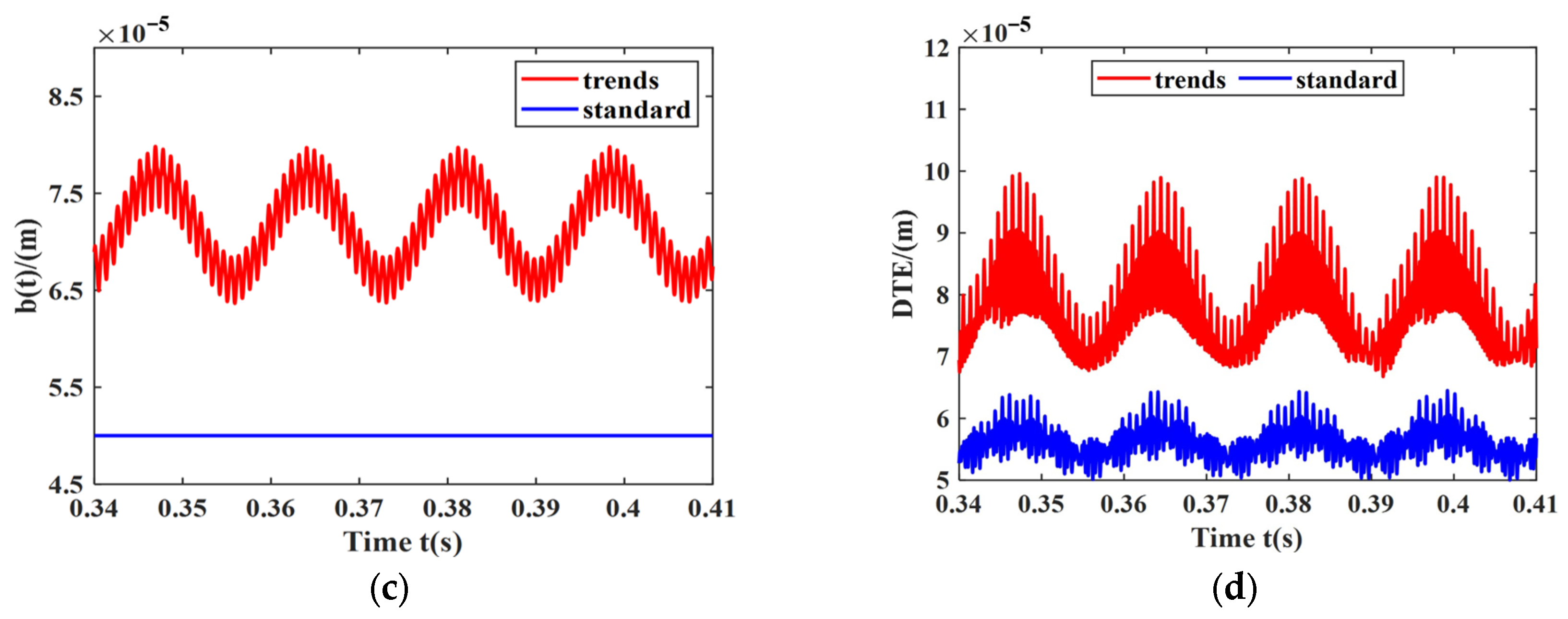
5.2. Calculation of Vibration Characteristics of the Gear-Bearing Transmission Systems Based on Dynamic Meshing Parameters

To further analyze the influence of dynamic meshing parameters on the vibration characteristics of the gear-bearing transmission system, a series of studies were conducted on the gear-bearing structure depicted in Figure 7.
Assuming that the active wheel support is a nonlinear spring, the driven wheel support is a linear spring, the mass eccentricity is zero, and the external input–output torque ( T 1 and T 2 ) is a fluctuating torque, in this section, the system’s vibration characteristics were calculated using numerical methods and compared with the old model that neglects dynamic meshing parameters and bearing clearance. The gear parameters are the same as those in Section 5.1, while the bearing parameters are detailed in Table 2.
T 1 = T o 1 + T a 1 sin ω p t
T 2 = T o 2 + T a 2 sin Z g Z p ω p t
In Equations (31) and (32), T o 1 and T o 2 denote the average torque; T a 1 and T a 2 denote the torque fluctuation amplitude.
A dynamic model of the gear-bearing system in the literature [31] is established, considering the gear meshing parameters, dynamic gear backlash, and dynamic bearing clearance. To verify the accuracy of the dynamic model developed in this paper, simulation experiments were conducted.
First, a 3D gear model was created based on the gear parameters listed in Table 1, and a bearing module was referenced at the bearing locations. The gear-bearing system model is shown in Figure 8a. Next, the solid model was imported into finite element software for simulation analysis. Tetrahedral elements were used to discretize the mesh with a mesh size of 5 mm. The gears divide 117,814 elements and 176,252 nodes. The result is shown in Figure 8b. Finally, the displacement of the driving gear along the direction perpendicular to the centerline connecting the gear’s geometric centers was calculated and compared with the theoretical results. As can be seen from Figure 8c,d, the theoretical and simulation results are in close agreement.
To further investigate the differences between the new and old models, the system’s dynamic response at rotational speeds of 1000 RPM and 3500 RPM, with a bearing clearance of 10 μm connected to the main wheel, is taken as an example in Figure 9, Figure 10, Figure 11 and Figure 12.
The calculated TVMS of the gears and its amplitude–frequency transformation, dynamic center distance, contact ratio, pressure angle, deflection angle, dynamic tooth flank clearance, and dynamic transmission error with time are shown in Figure 9 when the speed of the main wheel is 1000 RPM and the bearing clearance is 10 μm.
From Figure 9a,b, it is evident that the meshing frequency (16.67 × 20 = 333.33 Hz) and its harmonics appear in the spectrum of the standard gear meshing stiffness, while the rotational frequency (1000/60 = 16.67 Hz), meshing frequency, the harmonics of the meshing frequency, as well as combination frequencies appear in the meshing stiffness plot of the existing model. The coupling between gear meshing parameters and system vibration induces time-varying characteristics in the center distance, contact ratio, pressure angle, and deflection angle.
From Figure 9c–f, the gear center distance, contact ratio, pressure angle, and deflection angle all exhibit fluctuating patterns. The centers of these fluctuations are as follows: the fluctuation center of the gear center distance is 200.06 mm; the contact ratio fluctuates around 1.551; the pressure angle fluctuates around 20.03°; and the deflection angle fluctuates around 0.025°. Except for the contact ratio, these fluctuation centers are all greater than the theoretical values obtained from the model, which does not consider dynamic meshing parameters.
From Figure 10, it is evident that the rotational frequency (1000/60 = 16.67 Hz), the meshing frequency (16.67 × 20 = 333.33 Hz), and their multiplicative and combined frequencies appear in the spectrogram, and the gear half-tooth side clearance fluctuates around 70.13 μm, which is higher than the initial value of 50 μm. It can be seen that considering the dynamic meshing parameter and the dynamic gear and bearing clearances, the dynamic transmission error (DTE) fluctuations significantly increased.
The calculated TVMS of the gears and its amplitude–frequency transformation, dynamic center distance, overlap, pressure angle, deflection angle, dynamic tooth flank clearance, and dynamic transmission error with time are depicted in Figure 11 when the speed of the main wheel is 3500 RPM and the bearing clearance is 10 μm.
From Figure 11a–f, it can be observed that the TVMS calculated by the new model is slightly smaller in amplitude compared to the old model. The rotational frequency (58.33 × 20 = 1166.67 Hz) and its harmonics appear in the FFT spectrum of km. Due to the coupling between the gear meshing parameters and the vibration response of the gear-bearing system, the gear center distance, overlap ratio, pressure angle, and deflection angle fluctuate with gear vibration. The fluctuation centers are as follows: the fluctuation center of the gear center distance is 200.065 mm; the contact ratio fluctuates around 1.5513; the pressure angle fluctuates around 20.052°; and the deflection angle fluctuates around 0.025°. Except for the contact ratio, the fluctuation centers of these parameters are all greater than the theoretical values calculated by the old model.
From Figure 12, it is evident that the rotational frequency (3500/60 = 58.33 Hz), the meshing frequency (58.33 × 20 = 1166.67 Hz), and their multiplicative and combined frequencies appear in the spectrogram, and the gear half-tooth side clearance fluctuates around 72.65 μm, which is higher than the initial value of 50 μm. It is evident that considering the dynamic meshing parameter and the dynamic gear and bearing clearances, the fluctuation in DTE significantly increased.
In summary, it is evident that with increasing rotational speed, the center distance enlarges, the gear half-tooth side clearance and pressure angle increase, the deflection angle becomes larger, overlap increases, and the fluctuation in dynamic transmission error (DTE) intensifies.

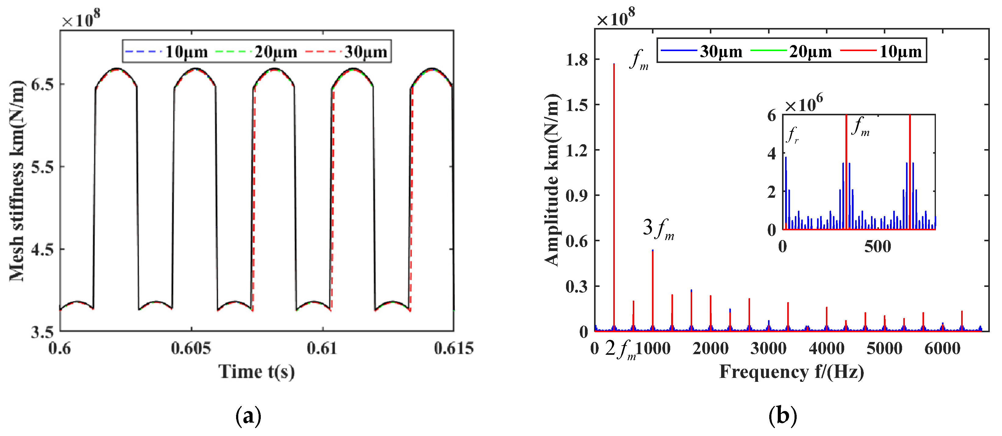
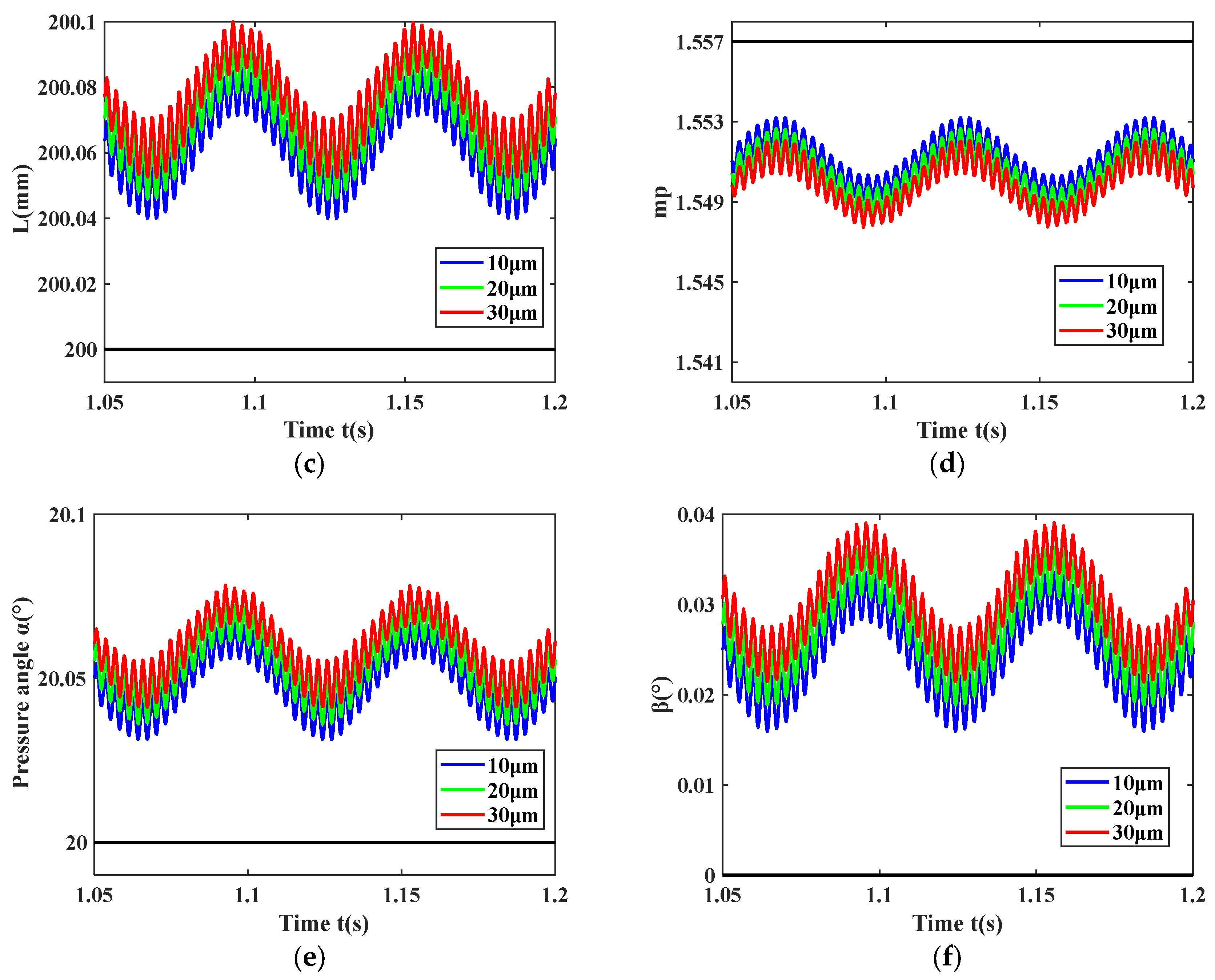
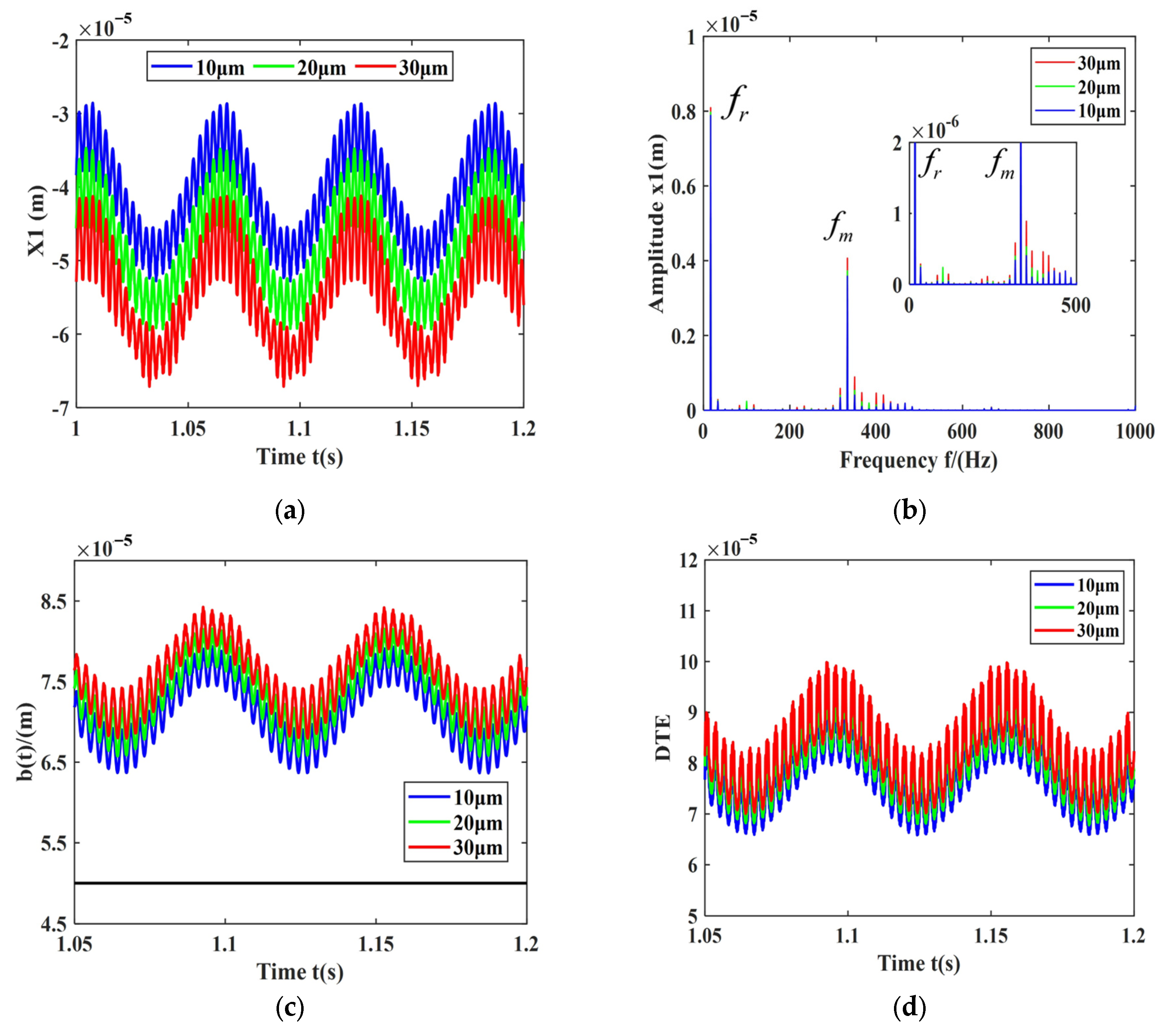
5.3. Influence of Bearing Clearance on Gear-Bearing Systems

As widely acknowledged, bearing clearance in gear-bearing systems is inevitable, leading to increased occurrences of gear impacts and tooth separation. As discussed in Section 3, the bearing clearance varies with time rather than remaining constant, and its increase or decrease leads to different dynamic characteristics. The initial bearing clearance in a gear-bearing system can vary during installation. Hence, examining the influence of initial bearing clearance on the dynamic characteristics of gear-bearing systems is crucial.
Assuming a gear-bearing transmission system depicted in Figure 7, with a central wheel speed of 3500 RPM and an initial bearing clearance of 10 μm, 20 μm, and 30 μm, the computed TVMS of the gears and their amplitude–frequency transformations, dynamic center distances, contact ratio, pressure angles, deflection angles, dynamic gear clearances, and dynamic transmission errors over time are shown in Figure 13.
From Figure 13, it is evident that as the initial bearing clearance increases, the frequency and amplitude variations in meshing stiffness become more pronounced. Additionally, the center distance increases overall, the contact ratio decreases overall, the instantaneous pressure angle increases overall, and the deflection angle increases overall.
From Figure 14 with the increase in the initial bearing clearance, the displacement of the driving gear in the ×1 direction increases overall. From Figure 14b, it can also be observed that the amplitudes corresponding to the rotational frequency and meshing frequency increase as the clearance increases. In the frequency spectrum of the driving gear, no new frequencies are added, and the increase in amplitude of the rotational frequency is greater than the increase in amplitude of the meshing frequency. Additionally, the variation in DTE becomes more pronounced with the increase in initial bearing clearance.

6. Conclusions

This paper has established a nonlinear dynamic model of a gear-bearing transmission system considering dynamic meshing parameters. Based on this, the effects of center distance, pressure angle, and meshing angle on gear meshing stiffness have been analyzed. Additionally, the variations in meshing stiffness, meshing parameters, and driving wheel response of the gear system have been analyzed under different gear speeds and initial bearing clearances. The main conclusions are as follows:
(1)
The variation in the relative positions of the gears leads to changes in the amplitude and range of gear meshing stiffness. This change in relative gear positions is also reflected in the variations in the center distance and contact ratio. As the relative positions of the gears increase, the center distance increases while the contact ratio decreases. The amplitude of meshing stiffness diminishes, while the frequency of gear meshing stiffness increases;
(2)
During gear rotation, the meshing parameters of the gear fluctuate over time. As the speed increases, the center distance of the gear, pressure angle, offset angle, contact ratio, and tooth side clearance increase as a whole;
(3)
Under the condition of a fixed initial gear backlash, changes in the initial bearing clearance affect the dynamic characteristics of the gear-bearing transmission system. As the initial bearing clearance increases, the amplitudes corresponding to the rotational frequency and meshing frequency gradually increase, and the amplitudes of other frequencies also increase. The center distance, instantaneous pressure angle, deflection angle, lateral displacement of the driving gear, half-tooth side clearance, and contact ratio decrease, while the dynamic tooth engagement (DTE) shows more significant variation.
The research findings in this paper can make specific contributions to the structure design of gear systems and provide support for the system’s structural optimization and vibration control.

Author Contributions

Conceptualization, J.S., Y.C. (Yushu Chen) and L.H.; methodology, J.S.; software, J.S. and Z.L.; validation, Z.L.; formal analysis, J.S.; investigation, J.S. and R.M.; resources, L.H. and Z.L.; data curation, N.A.S.; writing—original draft preparation, J.S. and Y.C. (Yi Chen); writing—review and editing, J.S., L.H. and Y.C. (Yushu Chen); visualization, R.M., R.L. and Y.C. (Yi Chen); supervision, L.H. and Z.L.; project administration, N.A.S.; funding acquisition, L.H. All authors have read and agreed to the published version of the manuscript.

Funding

This research was funded by the National Natural Science Foundation of China, grant numbers 12422213, 12372008, and U244120491; the National Key R&D Program of China, grant number 2023YFE0125900; and the Independent Innovation Fund of Tianjin University, grant number 2024XJS-0027. The authors extend their appreciation to King Saud University for funding this work through the Research Supporting Project number (RSPD2024R535), King Saud University, Riyadh, Saudi Arabia. The authors are grateful to the Raytheon Chair for Systems Engineering for funding.

Institutional Review Board Statement

This study was conducted according to the guidelines of the Declaration of Helsinki and approved by the Institutional Review Board.

Data Availability Statement

All data included in this study are available upon request by contact with the corresponding author.

Conflicts of Interest

The authors declare no conflicts of interest.

Appendix A

G , A y 1 , I y 1 , d y 1   d γ , l , and h can be expressed as follows:
G = E / 2 1 + ν
A y 1 = 2 x 1 B ,   I y 1 = 2 x 1 3 B 3
α 1 = acos ( rb p / ra p ) ,   α 2 = acos ( rb g / ra g )
l = rb 1 ( ( w t + θ b ) sin ( θ b ) + cos ( θ b ) )
h = rb 1 ( ( w t + θ b ) cos ( θ b ) sin ( θ b ) )
d y 1   d γ = a 1 sin φ ( 1 + tan 2 γ ) / tan 2 γ + a 1 cos γ sin ( γ + φ ) / sin 2 γ ( a 1 sin γ + r p ) cos ( γ + φ ) ( 1 + a 1 ( 1 + tan 2 γ ) r 1 tan 2 γ )
where φ , θ b , x 1 , y 1 , a 1 , and b 1 can be expressed as outlined below:
φ = a 1 tan γ + b 1 / r p
θ b = pi / ( 2 Z p ) + tan ( α 0 )     α 0
x 1 = r 1 sin ( φ ) a 1 sin γ + r p cos γ φ
y 1 = r 1 cos φ a 1 sin γ + r p cos ( γ φ )
a 1 = ( ha + hc ) m rp , b 1 = pi m / 4 + ha m tan ( α 0 ) + rp cos ( α 0 )
where w t represents the gear rotation angle; r p represents the pitch circle radius of the driving gear; rb represents the base circle radius; ra represents the addendum circle radius; r p represents the radius of the tool tip circle; ha = 1 ; hc = 0 . 25 .

Appendix B

Based on the theory of gear elasticity, the gear meshing force F d m can be obtained.
F d m = k m d δ d b t + c m d δ . d b . t 0 k m d δ d + b t + c m d δ . d + b . t δ d > b t δ d b t δ d b t
where the damping ratio is c m d = 2 ξ m k m J p J g J g r b p 2 + J p R r b g 2 ; ξ m is the damping coefficient; J p and J g are the moment of inertia of the driving wheel and the driven wheel.
δ . d = x p . δ d x p + y p . δ d y p + z p . δ d θ z p + x g . δ d x g + y g . δ d y g + z g . δ d θ z g + e .
b t . = r b p + r b g tan 2 α x p . δ d x p + y p . δ d y p + x g . δ d x g + y g . δ d y g
F d m q s = k m d δ d q s b t q s + c m d δ . d q s b . t q s 0 k m d δ d q s + b t q s + c m d δ . d q s + b . t q s δ d > b t δ d b t δ d b t
where
δ d x p = sin α β + x p x g cos α β y p y g sin α β α x p β x p
δ d y p = cos α β + x p x g cos α β y p y g sin α β α y p β y g
δ d x g = sin α β + x p x g cos α β y p y g sin α β α x g β x g
δ d y g = cos α β + x p x g cos α β y p y g sin α β α y g β y g
δ d θ z p = r b p ,   δ d θ z g = r b g
α x p = α x g = r b p + r b g x g x p + L 0 x g x p + L 0 2 + y g y p 2 x g x p + L 0 2 + y g y p 2 r b p + r b g 2
α y p = α y g = r b p + r b g y g y p x g x p + L 0 2 + y g y p 2 x g x p + L 0 2 + y g y p 2 r b p + r b g 2
β x p = β x g = y g y p x g x p + L 0 2 + y g y p 2
β y p = β y g = x g x p + L 0 x g x p + L 0 2 + y g y p 2

References

  1. Rincon, A.F.D.; Viadero, F.; Iglesias, M.; de-Juan, A.; Garcia, P.; Sancibrian, R. Effect of cracks and pitting defects on gear meshing. Proc. Inst. Mech. Eng. Part C J. Mech. Eng. Sci. 2012, 226, 2805–2815. [Google Scholar] [CrossRef]
  2. Yang, D.C.H.; Lin, J.Y.; Damping, H. Tooth Friction and Bending Elasticity in Gear Impact Dynamics. J. Mech. Transm. Autom. Des. 1987, 109, 189–196. [Google Scholar] [CrossRef]
  3. Tian, X.; Zuo, M.J.; Fyfe, K.R. Analysis of the Vibration Response of a Gearbox With Gear Tooth Faults. Am. Soc. Mech. Eng. Digit. Collect. 2008, 785–793. [Google Scholar] [CrossRef]
  4. Zhou, X.; Shao, Y.; Lei, Y.; Zuo, M. Time-Varying Meshing Stiffness Calculation and Vibration Analysis for a 16DOF Dynamic Model With Linear Crack Growth in a Pinion. J. Vib. Acoust. 2012, 134, 011011. [Google Scholar] [CrossRef]
  5. Chen, Z.; Shao, Y. Mesh stiffness calculation of a spur gear pair with tooth profile modification and tooth root crack. Mech. Mach. Theory 2013, 62, 63–74. [Google Scholar] [CrossRef]
  6. Ma, H.; Song, R.; Pang, X.; Wen, B. Time-varying mesh stiffness calculation of cracked spur gears. Eng. Fail. Anal. 2014, 44, 179–194. [Google Scholar] [CrossRef]
  7. Luo, Y.; Baddour, N.; Liang, M. Effects of gear center distance variation on time varying mesh stiffness of a spur gear pair. Eng. Fail. Anal. 2017, 75, 37–53. [Google Scholar] [CrossRef]
  8. Dai, H.; Long, X.; Chen, F.; Xun, C. An improved analytical model for gear mesh stiffness calculation. Mech. Mach. Theory 2021, 159, 104262. [Google Scholar] [CrossRef]
  9. Yang, H.; Shi, W.; Chen, Z.; Guo, N. An improved analytical method for mesh stiffness calculation of helical gear pair considering time-varying backlash. Mech. Syst. Signal Proc. 2022, 170, 108882. [Google Scholar] [CrossRef]
  10. Liu, Z.; Jiang, Y.; Luo, R.; Wu, Y.; Huang, J.; Feng, N.; Li, K. Improved analytical model for calculating mesh stiffness and transmission error of helical gears considering root curve: Theoretical analysis and experiments. Adv. Mech. Eng. 2024, 16, 16878132241228196. [Google Scholar] [CrossRef]
  11. Guo, Y.; Parker, R.G. Analytical determination of back-side contact gear mesh stiffness. Mech. Mach. Theory 2014, 78, 263–271. [Google Scholar] [CrossRef]
  12. Cheng, G.; Xiao, K.; Wang, J.; Pu, W.; Han, Y. Calculation of Gear Meshing Stiffness Considering Lubrication. J. Tribol. Trans. ASME 2020, 142, 031602. [Google Scholar] [CrossRef]
  13. Blankenship, G.W.; Kahraman, A. Steady state forced response of a mechanical oscillator with combined parametric excitation and clearance type non-linearity. J. Sound Vib. 1995, 185, 743–765. [Google Scholar] [CrossRef]
  14. Al-shyyab, A.; Kahraman, A. Non-linear dynamic analysis of a multi-mesh gear train using multi-term harmonic balance method: Sub-harmonic motions. J. Sound Vib. 2005, 279, 417–451. [Google Scholar] [CrossRef]
  15. Chen, Q.; Ma, Y.; Huang, S.; Zhai, H. Research on gears’ dynamic performance influenced by gear backlash based on fractal theory. Appl. Surf. Sci. 2014, 313, 325–332. [Google Scholar] [CrossRef]
  16. Cao, Z.; Shao, Y.; Rao, M.; Yu, W. Effects of the gear eccentricities on the dynamic performance of a planetary gear set. Nonlinear Dyn. 2018, 91, 1–15. [Google Scholar] [CrossRef]
  17. Zhao, B.; Huangfu, Y.; Ma, H.; Zhao, Z.; Wang, K. The influence of the geometric eccentricity on the dynamic behaviors of helical gear systems. Eng. Fail. Anal. 2020, 118, 104907. [Google Scholar] [CrossRef]
  18. Han, J.; Liang, L.; Zhang, H.; Zhao, Y. Dynamics Modeling and Experimental Investigation of Gear Mechanism with Coupled Small Clearances. Entropy 2021, 23, 834. [Google Scholar] [CrossRef]
  19. Liu, Z.; Liu, Z.; Zhao, J.; Zhang, G. Study on interactions between tooth backlash and journal bearing clearance nonlinearity in spur gear pair system. Mech. Mach. Theory 2017, 107, 229–245. [Google Scholar] [CrossRef]
  20. Meng, Z.; Shi, G.; Wang, F. Vibration response and fault characteristics analysis of gear based on time-varying mesh stiffness. Mech. Mach. Theory 2020, 148, 103786. [Google Scholar] [CrossRef]
  21. Han, Y.; Chen, X.; Xiao, J.; Gu, J.X.; Xu, M. An Improved Coupled Dynamic Modeling for Exploring Gearbox Vibrations Considering Local Defects. J. Dyn. Monit. Diagn. 2023, 262–274. [Google Scholar] [CrossRef]
  22. Fukata, S.; Gad, E.; Kondou, T.; Ayabe, T.; Tamura, H. On the Radial Vibration of Ball-Bearings—Computer-Simulation. Bull. Jsme-Jpn. Soc. Mech. Eng. 1985, 28, 899–904. [Google Scholar] [CrossRef]
  23. Sawalhi, N.; Randall, R.B. Simulating gear and bearing interactions in the presence of faults—Part II: Simulation of the vibrations produced by extended bearing faults. Mech. Syst. Signal Proc. 2008, 22, 1952–1966. [Google Scholar] [CrossRef]
  24. Tu, W.; Shao, Y.; Mechefske, C.K. An analytical model to investigate skidding in rolling element bearings during acceleration. J. Mech. Sci. Technol. 2012, 26, 2451–2458. [Google Scholar] [CrossRef]
  25. Zhang, X.; Han, Q.; Peng, Z.; Chu, F. Stability analysis of a rotor-bearing system with time-varying bearing stiffness due to finite number of balls and unbalanced force. J. Sound Vibr. 2013, 332, 6768–6784. [Google Scholar] [CrossRef]
  26. Bizarre, L.; Nonato, F.; Cavalca, K.L. Formulation of five degrees of freedom ball bearing model accounting for the nonlinear stiffness and damping of elastohydrodynamic point contacts. Mech. Mach. Theory 2018, 124, 179–196. [Google Scholar] [CrossRef]
  27. Xu, H.; Wang, P.; Yang, Y.; Ma, H.; Luo, Z.; Han, Q.; Wen, B. Effects of supporting stiffness of deep groove ball bearings with raceway misalignment on vibration behaviors of a gear-rotor system. Mech. Mach. Theory 2022, 177, 105041. [Google Scholar] [CrossRef]
  28. Corral, E.; Moreno, R.G.; García, M.J.G.; Castejón, C. Nonlinear phenomena of contact in multibody systems dynamics: A review. Nonlinear Dyn. 2021, 104, 1269–1295. [Google Scholar] [CrossRef]
  29. Moreno, R.G.; Marques, F.; Abad, E.C.; Alonso, J.M.; Flores, P.; Castejon, C. Enhanced modelling of planar radial-loaded deep groove ball bearings with smooth-contact formulation. Multibody Syst. Dyn. 2024, 60, 121–159. [Google Scholar]
  30. Kim, W.; Yoo, H.H.; Chung, J. Dynamic analysis for a pair of spur gears with translational motion due to bearing deformation. J. Sound Vib. 2010, 329, 4409–4421. [Google Scholar] [CrossRef]
  31. Yi, Y.; Huang, K.; Xiong, Y.; Sang, M. Nonlinear dynamic modelling and analysis for a spur gear system with time-varying pressure angle and gear backlash. Mech. Syst. Signal Process. 2019, 132, 18–34. [Google Scholar] [CrossRef]
  32. Kong, X.; Ding, H.; Tang, J.; Hu, Z.; Chen, S. Bearing internal load analysis and fatigue life estimation based on nonlinear dynamic model of a gear system. J. Vib. Control 2022, 28, 1635–1642. [Google Scholar] [CrossRef]
  33. Guo, Y.; Parker, R.G. Dynamic Analysis of Planetary Gears With Bearing Clearance. J. Comput. Nonlinear Dyn. 2012, 7, 041002. [Google Scholar] [CrossRef]
  34. Liu, P.; Zhu, L.; Gou, X.; Shi, J.; Jin, G. Modeling and analyzing of nonlinear dynamics for spur gear pair with pitch deviation under multi-state meshing. Mech. Mach. Theory 2021, 163, 104378. [Google Scholar] [CrossRef]
  35. Zhang, C.; Wei, J.; Wang, F.; Hou, S.; Zhang, A.; Lim, T.C. Dynamic model and load sharing performance of planetary gear system with journal bearing. Mech. Mach. Theory 2020, 151, 103898. [Google Scholar] [CrossRef]
  36. Xu, M.; Han, Y.; Sun, X.; Shao, Y.; Gu, F.; Ball, A.D. Vibration characteristics and condition monitoring of internal radial clearance within a ball bearing in a gear-shaft-bearing system. Mech. Syst. Signal Process. 2022, 165, 108280. [Google Scholar] [CrossRef]
  37. Li, H.; Chen, S.; Tang, J.; Sun, Z.; Hu, Y. Nonlinear dynamic modeling and analysis of spur gear based on gear compatibility conditions. Mech. Mach. Theory 2022, 171, 104767. [Google Scholar] [CrossRef]
  38. Zeng, Q.; Liu, Y.; Du, W.; Jiang, L.; Yu, W. Dynamic characteristic analysis of a gear-rotor-bearing coupling system considering bearing fit. Nonlinear Dyn. 2024, 113, 2131–2154. [Google Scholar] [CrossRef]
  39. Tian, G.; Gao, Z.; Liu, P.; Bian, Y. Dynamic Modeling and Stability Analysis for a Spur Gear System Considering Gear Backlash and Bearing Clearance. Machines 2022, 10, 439. [Google Scholar] [CrossRef]
  40. Xu, Z.; Yu, W.; Xu, H.; Li, J. Dynamic modeling of spur gear system considering the coupling effect between bearing deflection and gear mesh stiffness. Proc. Inst. Mech. Eng. Part C-J. Eng. Mech. Eng. Sci. 2024, 238, 6725–6737. [Google Scholar] [CrossRef]
  41. Guan, H. Study on dynamic characteristics of the gear-dual-rotor system with multi-position rubbing. Mech. Mach. Theory 2024. [Google Scholar] [CrossRef]
  42. Ma, H.; Pang, X.; Feng, R.; Song, R.; Wen, B. Fault features analysis of cracked gear considering the effects of the extended tooth contact. Eng. Fail. Anal. 2015, 48, 105–120. [Google Scholar] [CrossRef]
  43. Chen, Y.; Hou, L.; Chen, G.; Song, H.; Lin, R.; Jin, Y.; Chen, Y. Nonlinear dynamics analysis of a dual-rotor-bearing-casing system based on a modified HB-AFT method. Mech. Syst. Signal Process. 2023, 185. [Google Scholar] [CrossRef]
  44. Bahan, D. Nonlinear Vibration Analysis of Rotors Supported by Ball Bearings. Master’s Thesis, Middle East Technical University, Ankara, Turkey, 2019. [Google Scholar]
  45. Niu, Q.; Li, Y.; Zhu, Y.; Pei, S.; Yin, Y.; Wang, D. Analytical Determination and Influence Analysis of Stiffness Matrix of Ball Bearing under Different Load Conditions. Machines 2022, 10, 238. [Google Scholar] [CrossRef]
  46. Anoopnath, P.R.; Babu, V.S.; Vishwanath, A.K. Hertz Contact Stress of Deep Groove Ball Bearing. In Materials Today-Proceedings; Elsevier: Amsterdam, The Netherlands, 2018. [Google Scholar]
Figure 1. Configuration for a pair of spur gears.
Machines 13 00230 g001
Figure 2. Boundary conditions of modification area.
Machines 13 00230 g002
Figure 3. Fitting curve: (a) mesh-stiffness fitting curve with pressure angle; (b) a pair of gear-mesh-stiffness fitting curves.
Machines 13 00230 g003
Figure 4. Diagram of single- and double-tooth meshing relationship.
Machines 13 00230 g004
Figure 5. Diagram of the initial position of the gear system.
Machines 13 00230 g005
Figure 6. Plot of variation in parameters such as meshing stiffness based on dynamic meshing parameters of gears: (a) time-varying mesh stiffness; (b) FFT spectrum of km; (c) gear center distance.
Machines 13 00230 g006
Figure 7. Schematic diagram of gear-bearing structure.
Machines 13 00230 g007
Figure 8. Simulation experiment: (a) gear-bearing system model; (b) gear mesh division diagram; (c) comparison of FEM and theoretical displacement; (d) comparison of the FFT between FEM and theoretical displacement.
Machines 13 00230 g008
Figure 9. Variation in gear meshing parameters at 1000 rad/min of the action wheel: (a) TVMS; (b) FFT spectrum of km; (c) center distance; (d) contact ratio; (e) pressure angle; (f) deflection angle.
Machines 13 00230 g009
Figure 10. Gear response diagram at 1000 rad/min for the active wheel: (a) transverse displacement of active wheel; (b) FFT spectrum of ×1; (c) gear half-tooth side clearance; (d) DTE.
Machines 13 00230 g010
Figure 11. Variation in gear meshing parameters at 3500 rad/min of the action wheel: (a) TVMS; (b) FFT spectrum of km; (c) center distance; (d) contact ratio; (e) pressure angle; (f) deflection angle.
Machines 13 00230 g011aMachines 13 00230 g011b
Figure 12. Gear response diagram at 3500 rad/min for the active wheel: (a) transverse displacement of active wheel; (b) FFT spectrum of ×1; (c) gear half-tooth side clearance; (d) DTE.
Machines 13 00230 g012aMachines 13 00230 g012b
Figure 13. Variations in gear meshing parameters under different initial bearing clearances: (a) TVMS; (b) FFT spectrum of km; (c) center distance; (d) contact ratio; (e) pressure angle; (f) deflection angle.
Machines 13 00230 g013aMachines 13 00230 g013b
Figure 14. Vibration characteristics of gears with different initial bearing clearances: (a) transverse displacement of active wheel; (b) FFT spectrum of ×1; (c) gear half-tooth side clearance; (d) DTE.
Machines 13 00230 g014
Table 1. Gear parameters.
Physical ParametersVariableValue
Number of teeth of wheel Z p ,   Z g 20
Modulus (mm) m 10
Elastic modulus (GPa) E 206
Standard pressure angle (°) α 0 20
Tooth width (mm) B 30
Standard center distance (mm) L 0 200
Static transmission error amplitude (μm) e a 20
Mass of wheel (kg) m p ,   m g 6.57
Moment   of   inertia   ( kg · m 2 ) J p ,   J g 0.0365
Damping factor ξ m 0.07
Torque average (N·m) T o 1 ,   T o 2 300
Torque amplitude (N·m) T a 1 ,   T a 2 100
Initial half-tooth clearance measurement (μm) b 0 50
Table 2. Rolling-ball-bearing structure parameters.
Physical ParametersVariableValue
Inner circle radius (mm) r i 10
Outer circle radius (mm) r o 23.5
Bearing widths (mm)B14
Number of balls N b 10
Bearing damping (N·s/m) c b 512.64
Hertz contact stiffness (N/m) K b 2 × 10⁸
Disclaimer/Publisher’s Note: The statements, opinions and data contained in all publications are solely those of the individual author(s) and contributor(s) and not of MDPI and/or the editor(s). MDPI and/or the editor(s) disclaim responsibility for any injury to people or property resulting from any ideas, methods, instructions or products referred to in the content.

